
Abstract
The long-span steel box self-anchored track suspension bridge is prone to deformation under long-term train and temperature loads, which seriously affects the structural safety and operation performance. To ensure the operational performance of the long-span steel box self-anchored track suspension bridge, this paper determines the operational performance evaluation index through an investigation and analysis of relevant norms and standards from both domestic and international sources. Based on the theory of couple vibration and track irregularity, Midas/Civil software was used to analyze the vertical displacement of a long-span steel box self-anchored track suspension bridge under loads such as train and temperature, and put forward the operation safety classification evaluation index and derived the control value, and verified the index combined with the actual project. The results show that the down-torsion will significantly change the structure alignment and seriously affect the operation performance of the bridge. Due to the limited adjustment of the number of fasteners of long-span ballastless track Bridges, the deformation range should be set effectively. Based on the analysis results, the maximum vertical deformation safety control value of the railway suspension bridge during operation is L/500, and the early-warning control value is L/600. Compared with the current monitoring standards, the safety control value is slightly smaller, and the warning value is the same. Through the real bridge test, the rationality of the maximum vertical deformation control value in the operation stage is verified.
Introduction
Urban track transit, with its advantages of convenience, economy, safety, and comfort, has been widely promoted and applied. In the process of construction, long-span track bridges came into being to cross special terrains such as mountains, valleys, and rivers. 1 Among them, track suspension bridges in the form of steel boxes are widely used because of their beautiful and smooth lines, strong crossing ability, and ability to adapt to various terrain restrictions.2,3
Since the bridge of urban track transit is usually paved with ballastless tracks, the irrecoverable deformation of the main beam can only be maintained by adjusting the fastener, which has limited ability to adjust the track shape. 1 In addition, the rigidity of this kind of long-span track suspension bridge is small, and the structure of the bridge will produce large deflection when the train is subjected to constant dynamic load. Therefore, in the process of bridge operation, it is necessary to analyze the operational behavior of long-span track suspension bridges.4,5 In other words, the two key indicators, operating comfort and safety, are used to determine the reasonable threshold for the train to pass the suspension bridge. In addition, the status of the bridge is monitored in real-time, and the operational behavior is controlled at different levels to ensure the safety and comfort of the train during running. However, at present, the rigidity under various load combinations lacks a unified limit standard, and only a separate deformation limit is set. As a result, each limit value in the design specification cannot be directly applied to the operational analysis and actual operation management of long-span track suspension bridges.
Therefore, domestic and foreign scholars have conducted in-depth research on bridge operational performance evaluation based on two aspects of train running safety and comfort, and bridge dynamic response analysis, relying on two theories of vehicle-bridge coupling vibration and train-rail-bridge dynamic interaction. For example, Hengtao Cao et al. developed Cmck 1.0, an analysis program for vehicle-bridge coupled vibration, and studied the influence factors of curvature radius, constraint mode, and vehicle characteristics on the coupled vibration of curved beam bridges. 6 Yan Wang et al. proposed a new method to analyze the coupling vibration between a vehicle and bridge, taking into account the spatiotemporal effects and mechanical phenomena caused by braking, to study the effects of different parameters on the mid-span displacement and impact factors of bridges. 7 Gou H. et al. studied the influence of various types of bridge deformation on the dynamic response of high-speed trains passing through the deformed bridge. 8 Liu L. et al. analyzed the dynamic response of the high-speed TTB(train-track-bridge) coupled system model and proposed the beam deformation threshold based on the operating safety and ride comfort indexes. 9 Li X. et al. studied the influence of vertical train acceleration on the deformation of long-span suspension bridges through the analysis and chord measurement of train-rail-bridge coupling vibration of dynamic space pairs. 10 Zhou L. et al. monitored the deformation of the Ganjiang bridge based on small baseline subset (SBAS) InSAR technology and Sentinel-1A data. 11 Xu C. et al. proposed a time-frequency domain analysis method for coupled system dynamic response and studied the vibration characteristics of long-span suspension bridges under the impact of high-speed trains. 12 Xu et al. proposed a real-time hybrid VBCS test (RTHT-RTHT) method (RTHT-VBCS) to accurately and economically reveal the dynamic performance of vehicle-axle coupled systems (VBCS). 13 Zhang et al. introduced a new 3D wheel-road coupling unit on the OpenSees platform to accurately calculate the dynamic response in the vehicle-bridge coupling system. 14
To sum up, the relationship between bridge foundation deformation, bridge alignment change, and operation status, and the influence of track irregularity on train operation has been sought based on the theory of vehicle-bridge coupling vibration analysis and the theory of interaction between vehicle and bridge. For long-span steel-box self-anchored track suspension bridges, the limit value of vertical displacement of bridges has rarely been analyzed through operational behavior.
Given this, based on the theory of vehicle-bridge coupling vibration and track irregularity, this research deduces the operational behavior analysis index of suspension bridges based on domestic and foreign norms. Then, by using the method of numerical analysis, the maximum deflection limit value of the bridge under operational conditions is put forward, and the operation classification evaluation index of the long-span track suspension bridge is proposed. Finally, based on the Chongqing Egongyan Rail-transit Bridge, a real bridge experiment was carried out to verify the indicators. It provides strong guidance for establishing the limited standard of bridge health monitoring systems helps the operation and maintenance of long-span steel box track suspension bridges, and effectively guarantees the safety and comfort of trains during running.
Vehicle-bridge coupling theory
Vehicle-bridge coupling vibration theory
The essence of vehicle-bridge coupling vibration is the dynamic interaction formed between the train and the bridge through wheel-rail contact: the train load stimulates the bridge vibration through the wheel-rail contact force, and the deformation of the bridge reacts on the train through the wheel-rail interface, changing the dynamic response of the train. Therefore, the analysis requires splitting the system into the train subsystem and the bridge subsystem, establishing motion equations, respectively, and then achieving coupling through the wheel-rail contact relationship.
System model and simplified assumptions
The train subsystem of this study adopts the two-series four-axle car of the 6-car formation of China Metro Type B as the model and uses the particle—spring—damper model, as shown in Figure 1. The train is divided into seven rigid bodies (including one car body, two bogies, and four wheel sets), and each rigid body has a total of 6 degrees of freedom in space. Each wheelset has two degrees of freedom. When the train moves forward, the stretching and contracting vibrations of the wheelset, the car body, and the bogie along the train’s movement direction have little impact on the train vibration and the bridge vibration. The stretching and contracting degrees of freedom of each rigid body of the train can be ignored. Both the car body and the bogie have five degrees of freedom, namely yaw, pitch, roll, nod, and shake. The entire train has a total of 23 degrees of freedom. Train analysis model.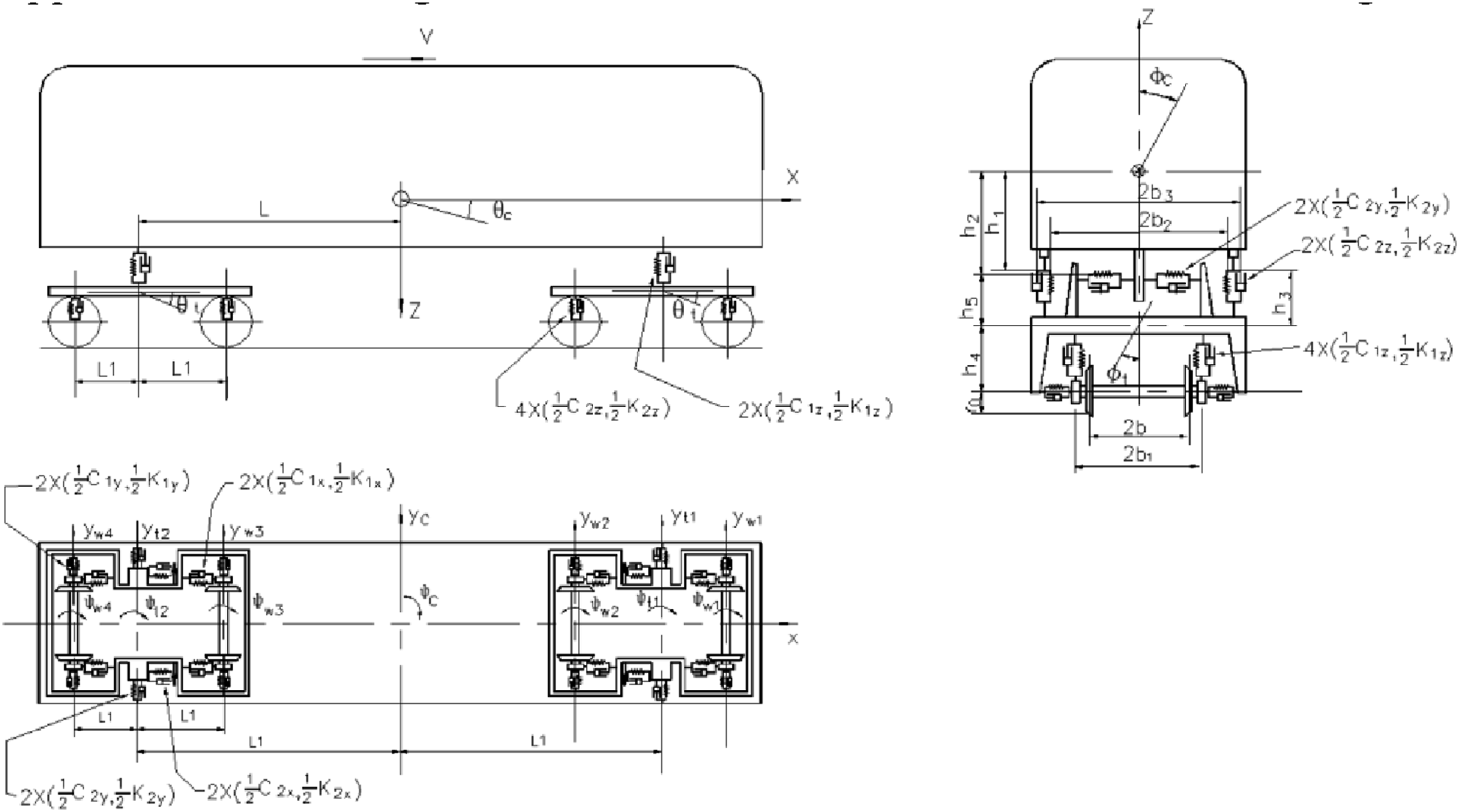
For the convenience of research and from the practical perspective of solving engineering problems, the following assumptions are made for the train model.
15
(1) The vehicle body, bogie, and wheel set are all regarded as rigid particles (rigid bodies) and only undergo slight vibrations. (2) Rigid bodies are connected through linear springs (primary suspension, secondary suspension) and viscous dampers, and the stiffness and damping coefficients of the springs are linear parameters. (3) The creep force of wheel-rail contact is calculated according to the linear theory. (4) The nonlinear influence of train power on the vibration phase of the bridge and the traveling speed is temporarily not considered. (5) The rails are regarded as infinitely long Euler beams supported by continuous elastic discrete points. The sleepers are considered rigid bodies, and the track beds are dispersed into mass blocks according to the spacing of the sleepers. Linear springs and viscous dampers are used to connect the sleepers with the rails and between the sleepers and the ballast in the vertical direction. The vertical vibration of the sleepers is taken into account. The mass of the track bed on the bridge is included in the second-phase deadload of the bridge, but the elastic and damping characteristics of the track bed are included in the model.
The bridge subsystem model was established using Midas civil, as shown in Figure 2. The model was divided into 937 nodes and 924 elements (674 beam elements and 250 tension elements). The main beam and bridge tower are simulated by beam elements. The main cable and boom are simulated by tension truss elements. The boundary and constraint conditions of the finite element model are set as follows: a fixed support is set at the bottom of the bridge tower; the main beam and the main cable anchor point, the main beam and the lower edge of the boom; the main cable and the main tower are rigidly connected. The elastic connection between the main beam and the support of the bridge tower is simulated, and the longitudinal direction of the bridge is unconstrained. The main beam at the auxiliary pier and junction pier adopts general support to release longitudinal constraints. The model is shown in Figure 2. Bridge analysis model.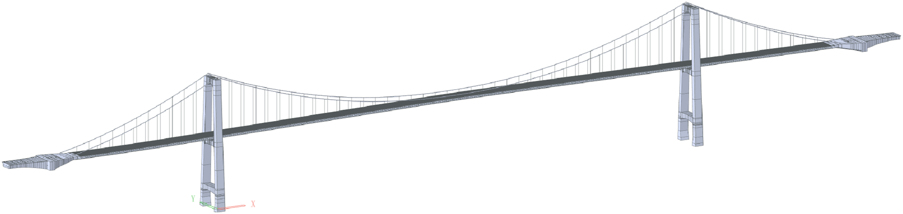
Derivation of the vehicle-bridge motion equation based on D’Alembert’s principle
The core of D’Alembert’s principle is that in a dynamic system, the vector sum of external forces, constraint forces, and inertial forces is zero. That is, by introducing inertial forces, the dynamic problem is transformed into a static equilibrium problem, from which the motion equations of the train subsystem and the bridge subsystem can be obtained. (1) Motion equation of the train subsystem
Taking rigid bodies such as the vehicle body, bogie, and wheels as the research objects, the forces they are subjected to include: inertial force, damping force, elastic force, and external force. According to the static equilibrium conditions of D'Alembert’s principle, it can be obtained that

The motion equations of the train subsystem are sorted out as follows (2) Motion equation of the bridge subsystem

Taking the nodes of the bridge finite element model as the research object, the forces also include: inertial force, damping force, elastic force, and external force. Similarly, according to the static equilibrium conditions of D'Alembert’s principle, it can be obtained that

The motion equation of the bridge subsystem has been sorted out as follows

The mass matrix

Verification based on Hamilton’s principle
Based on Hamilton’s principle, as shown in equation (6), the rationality of the equation is verified from the perspective of energy: the actual motion of the system causes the “action” to take an extreme value (1) Energy analysis of the train subsystem

The capabilities of the train subsystem include kinetic energy, potential energy, and non-conservative force work, which are calculated as follows:
Kinetic energy

Potential energy

By substituting the variational operation of Hamilton’s principle, the train motion equation consistent with equation (2) can be derived through the energy extremum condition. (2) Energy analysis of the bridge subsystem
The capabilities of the bridge subsystem include kinetic energy, potential energy, and non-conservative force work, which are calculated as follows:
Kinetic energy

Potential energy

Similarly, the correctness of equation (4) can be verified through the variation of Hamilton’s principle.
Wheel-rail coupling mechanism and equation coupling
The core coupling relationship of the axle system is through the wheel-rail contact force

Since the wheel-rail force satisfies Newton’s third law:

Theory of track irregularity
As an incentive, track irregularity is the main cause of train vibration. According to the different directions of the track section, track irregularity can be divided into horizontal and gauge irregularity, vertical irregularity, and direction irregularity. Horizontal irregularity indicates the vertical height difference of the left and right rail along the length direction. Gauge irregularity indicates the deviation between the nominal gauge and the actual gauge. Vertical irregularity represents the vertical geometric position deviation between the ideal track center line and the actual track center line along the track length. Directional irregularity represents the horizontal geometric position deviation between the ideal track center line and the actual track center line along the track length. According to the Power Spectral Density (PSD) model proposed by the FRA of the US Federal Railroad Administration, the degree of track irregularity at different frequencies can be described. Frequency domain analysis can be used to clarify the performance characteristics of the track in different frequency ranges, and the formulas are as follows
1
. ① Vertical irregularity ② Direction is not smooth ③ Uneven track and direction


Operational performance analysis indicators
Principles for establishing the operational performance evaluation index system
The long-span bridges are greatly affected by environmental factors. In the daily use process, the pre-set arch, ambient temperature, sunshine, wind, and other external factors often produce bridge deformation that cannot be ignored. The cumulative deformation of construction also affects the initial form of the bridge to a certain extent, which, together with bridge vibration and random irregularity of lines, constitutes the actual track surface state. Together, they affect the train performance. According to Code for design of metro,
16
Code for design of urban rail transit bridge,
17
Design standards for railway structures and restrictions on their interpretation of displacement,
18
Standard specification for test evaluation method and evaluation of dynamic performance of railway locomotive,
19
Railway vehicles-Specification evaluation the dynamic performance for an accreditation test,
20
Guidance on the assessment of passenger ride comfort in railway vehicle vibration,
21
the design of long-span bridges, the monitoring needs of health monitoring systems, and train dynamic response are comprehensively considered to determine operational performance evaluation. The process is as shown in Figure 3. Flow chart of operational performance evaluation.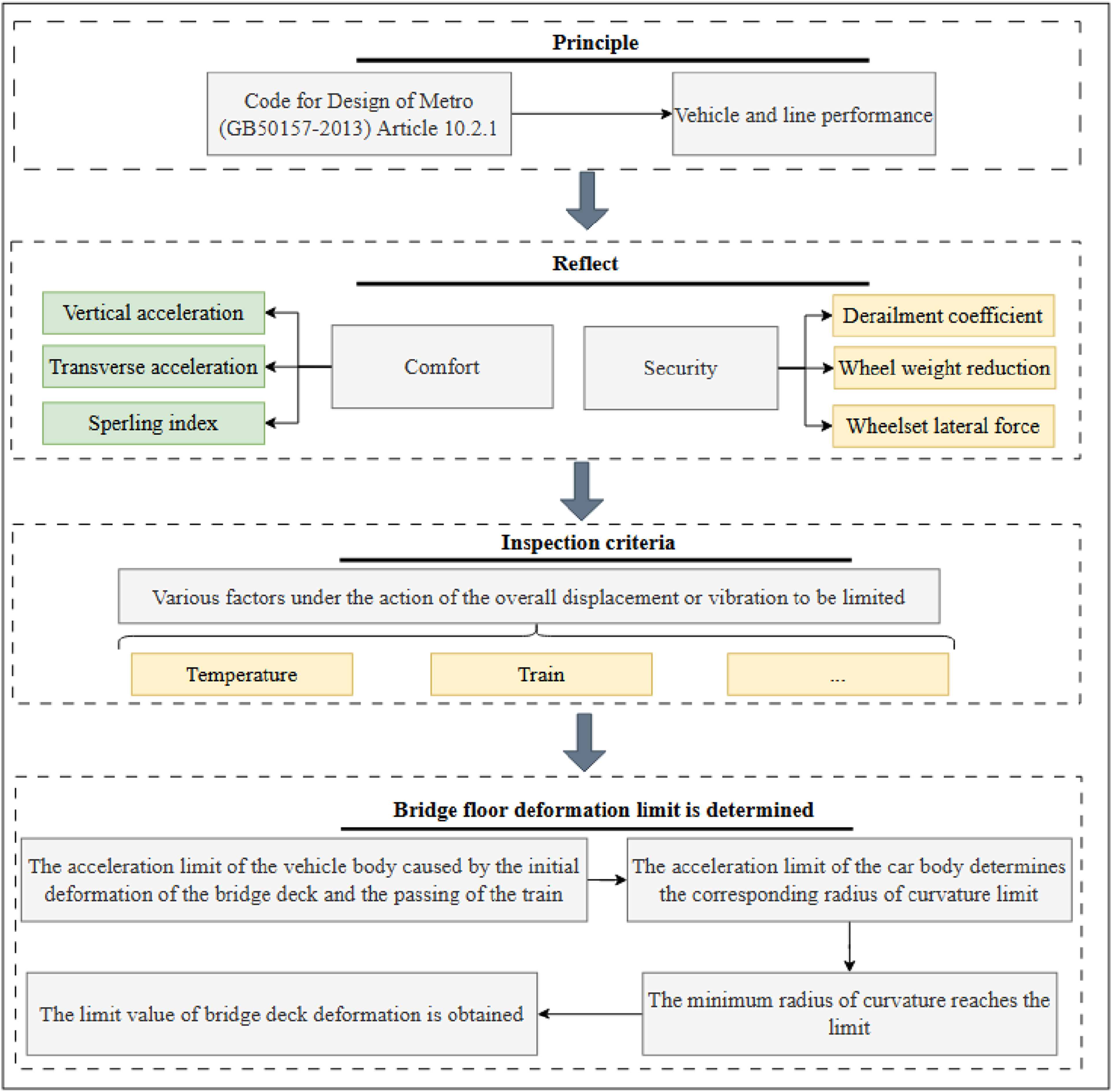
Based on the process shown in Figure 3, the determination of operational behavior evaluation indicators should follow the logical chain of “principle anchoring - dimension decomposition - multi-factor restriction - limit value derivation”: First, taking Article 10.2.1 of the “Code for design of metro,” 16 which states “meeting the performance requirements of vehicles and lines,” as the core principle, the evaluation dimensions are decomposed into safety and comfort. Safety is characterized by the derailment coefficient, wheel weight reduction rate, and lateral wheel-rail force to represent safety risks such as train overturning and derailment. Comfort is reflected in the coupling state of passenger experience and bridge stiffness by vertical acceleration, lateral acceleration, and the Sperling index. Then impose restrictions on the overall displacement or vibration under the influence of multiple factors, such as temperature and train. Ultimately, by analyzing the dynamic response of the vehicle without initial deformation, the difference between it and the vehicle body acceleration management standard was calculated. Combined with the influence correction margin of the cumulative deformation during construction, the vehicle body acceleration limit value under the combined effect of “initial deformation of the bridge deck and train passing” was derived. The bridge deck deformation limit value was obtained by reverse calculation, and a complete operational performance evaluation index system was constructed.
Establishment of operational performance evaluation indicators
Operational performance evaluation criteria.
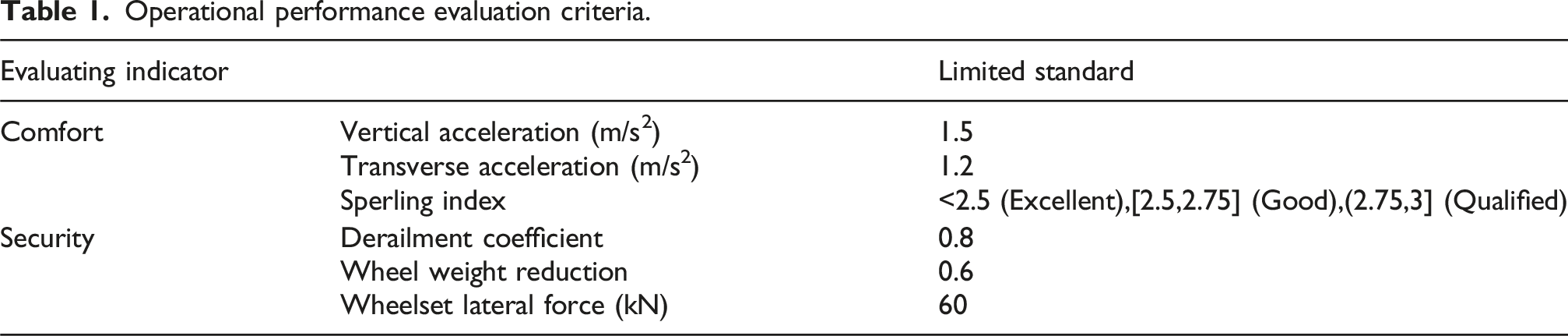
Among them, the limits of vertical acceleration and lateral acceleration refer to the “Code for design of urban rail transit bridge,” which stipulates that the vertical acceleration limit for metro bridges during train operation is 1.5 m/s2, and the lateral acceleration limit is 1.2 m/s2, to ensure that passengers do not experience discomfort or fatigue due to excessive vibration during the ride. 16 Sperling Index classification: The classification system based on the International Union of Railways (UIC) standard (UIC 513) is adopted: a Sperling index <2.5 is “excellent,” [2.5,2.75] is “good,” and (2.75,3] is “qualified.” This standard was established through a large number of subjective experience tests of passengers, directly associating vibration response with comfort levels. It is an internationally recognized method for evaluating train comfort. 21 The derailment coefficient refers to the regulation in Japan’s “Design standards for railway structures and restrictions on their interpretation of displacement” that “the limit value of the derailment coefficient is 0.8.” This standard is based on the research of the train derailment mechanism. Through the mechanical analysis and experimental verification of wheel-rail contact, it is concluded that when the derailment coefficient is ≤0.8, the risk of train derailment can be ignored. 18 The wheel weight load reduction rate is based on the requirement of “the limit value of wheel weight load reduction rate is 0.6” as stipulated in the “Standard specification for test evaluation method and evaluation of dynamic performance of railway locomotive.” 19 Wheel set lateral force: Refer to the regulation in “Railway vehicles-specification evaluation of the dynamic performance for an accreditation test” that “the limit value of wheel set lateral force is 60 kN.” 20
Comparative analysis of evaluation indicators
Comparison table of evaluation index and international norms.
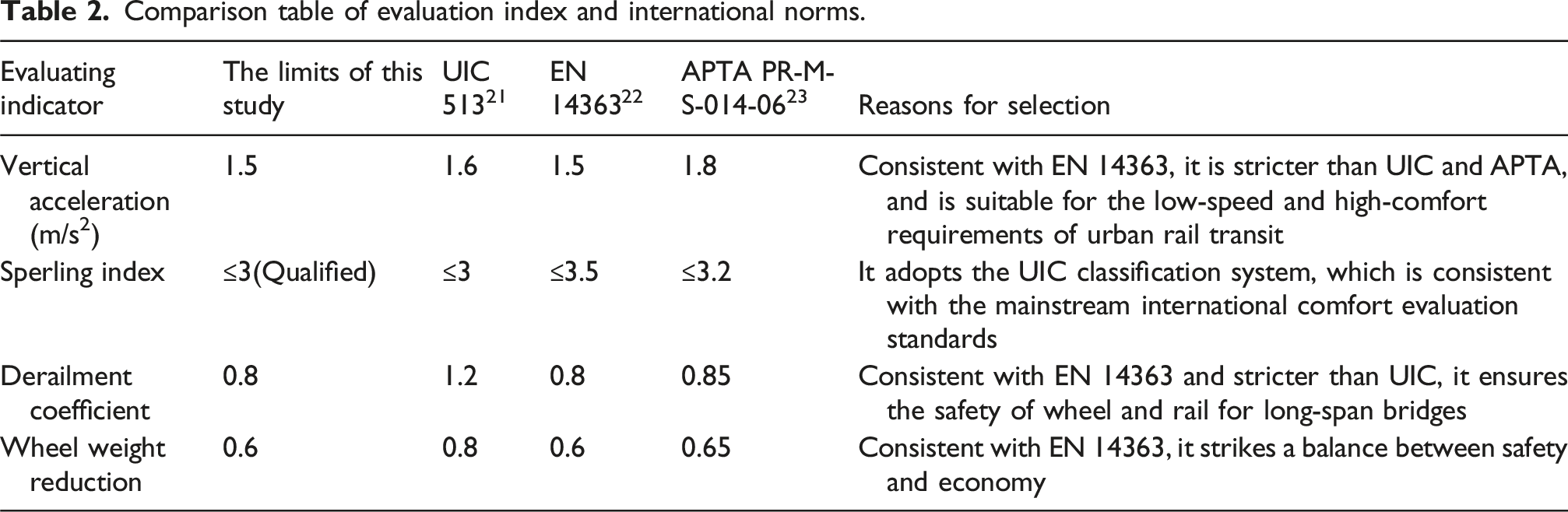
As can be seen from Table 2, the large-span steel box self-anchored rail suspension bridge, as a key hub of urban rail transit, its structural characteristics that require more stringent standards must be given priority when choosing evaluation indicators. For example, in terms of vertical acceleration, this study adopted 1.5 m/s2 in the EN 14,363 standard, which is a stricter indicator than the UIC standard; In terms of the derailment coefficient, 0.8 in the EN 14,363 standard was adopted in this study, which is stricter than the standard of the American Public Transportation Association. Through comparative analysis, we find that this study has chosen stricter standards in key indicators to ensure that sufficient safety redundancy is retained in large-span bridge types with greater flexibility, thereby effectively guaranteeing the operational safety of the bridge and the comfort of passengers.
Engineering applications
Project overview
The Chongqing Egongyan Rail-transit Bridge is the world’s largest span self-anchored railway special suspension bridge.
24
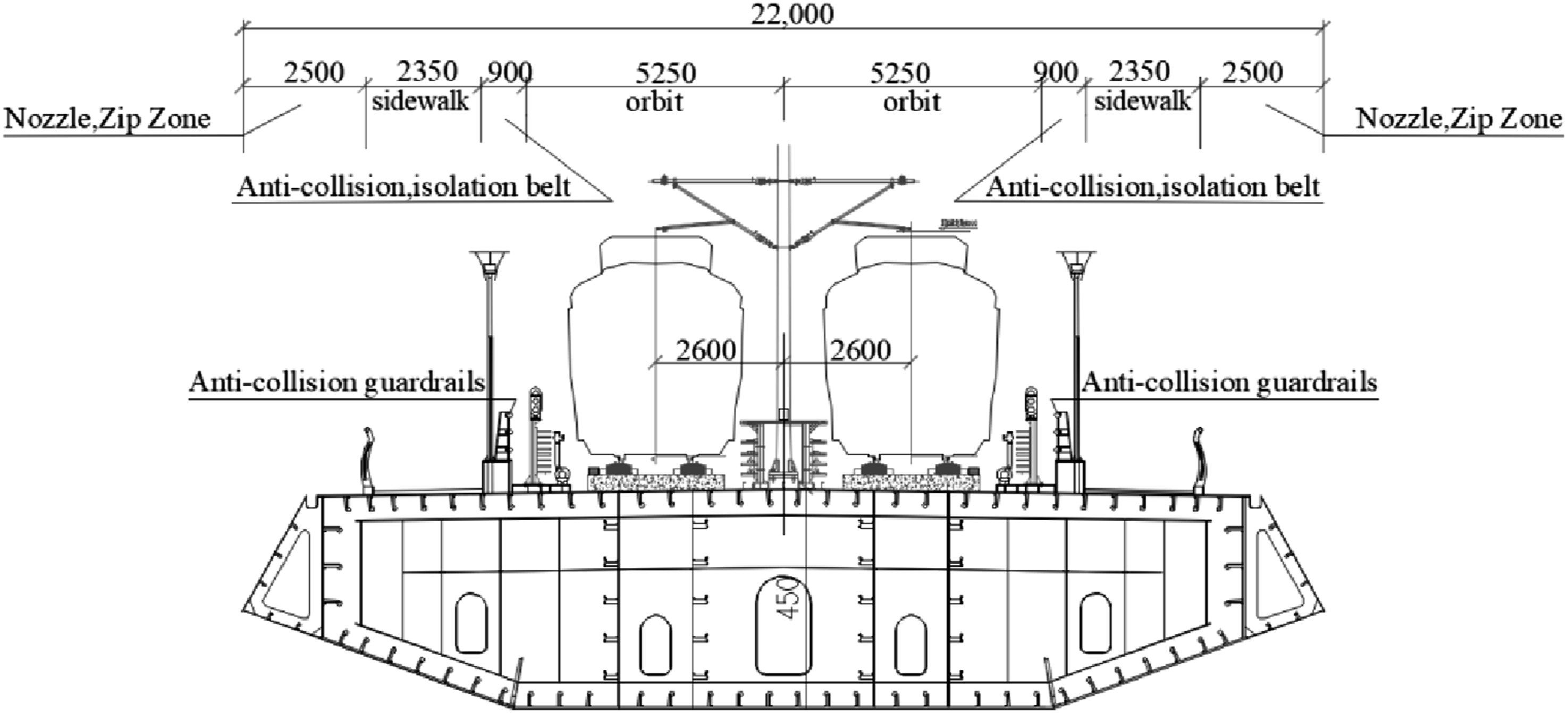
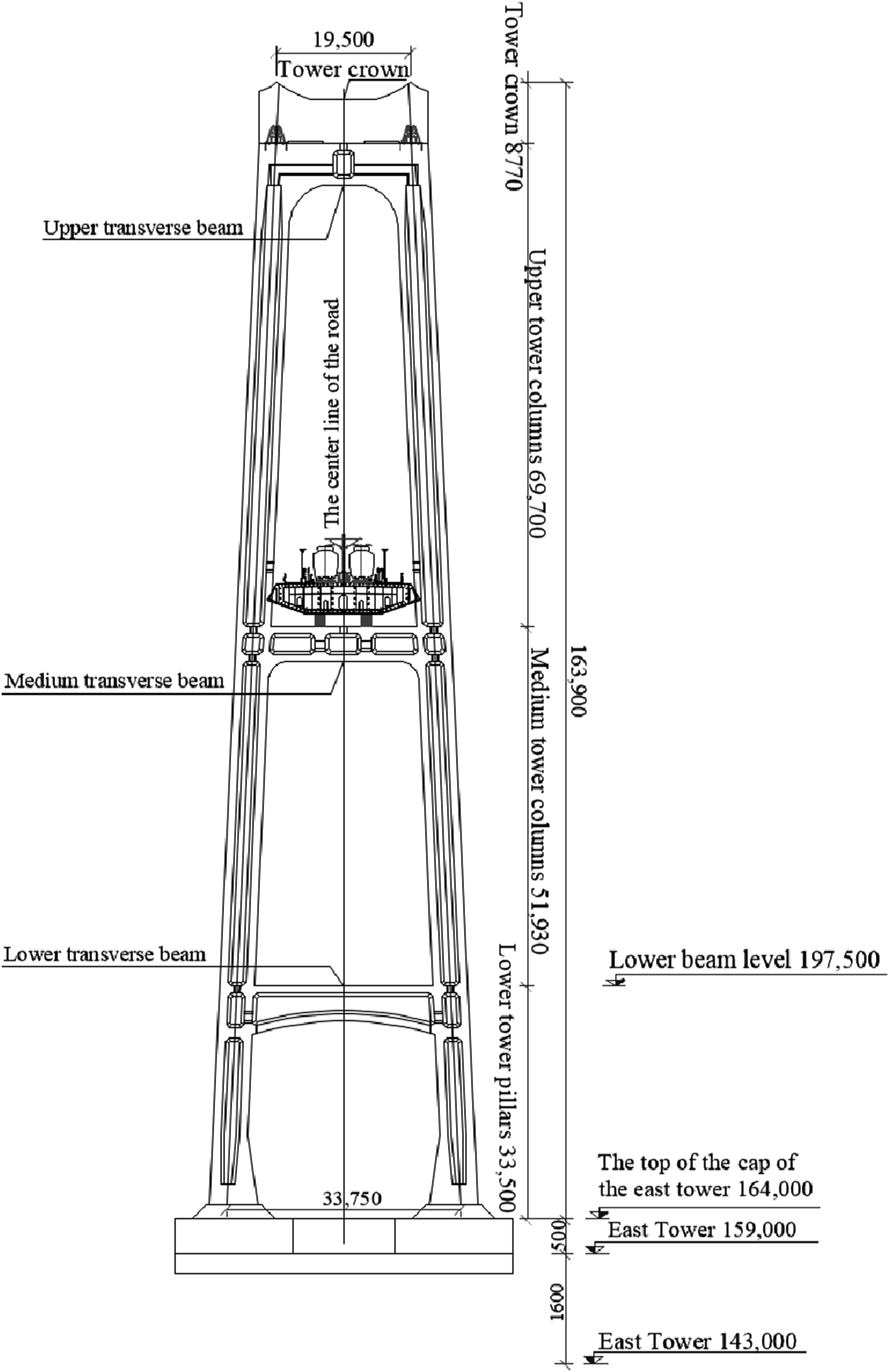
Its main bridge adopts a 5-span self-anchored suspension bridge structure, with span arrangement as follows: 50 +210 + 600 + 210 + 50 = 1120 m, and cross-section arrangement as follows: 2.25 (cable area, air nozzles) +0.25 (railing) +2.35 (sidewalk) +0.9 (anti-collision, isolation belt) +10.5 (track boundary) +0.9 (anti-collision, isolation belt) +2.35 (sidewalk) +0.25 (railing) +2.25 (cable area, air nozzles) = 22.0 m. There are two main cables in total, each of which contains 92 strands, and each strand is composed of zinc-aluminum alloy-coated high-strength steel wire, anchored at the end of the stiffened beam of the main bridge. The suspension rod is made of galvanized high-strength and low-relaxation parallel steel wire with PE material. There are 122 suspension rods in the whole bridge. The suspension rods are made of galvanized parallel steel wire with high strength and low relaxation, and are outsourced with PE material. The tensile strength of the steel wire is 1770 MPa. The main beam is a composite structure of a steel beam and a concrete beam. The main structure of the steel beam adopts Q420qD, and the prefabricated bridge panel adopts C55 concrete. The anchor section and anchor span section of the main cable are prestressed concrete box beams. The main pier is a reinforced concrete structure. The overall layout of the bridge is shown in Figure 4; The cross-section layout, as shown in Figure 5; The section view of the main tower, as shown in Figure 6. General layout of the Chongqing Egongyan Rail-transit Bridge (unit: mm). Cross-section layout of the Chongqing Egongyan Rail-transit Bridge (unit: mm). Section view of the main tower (unit: mm).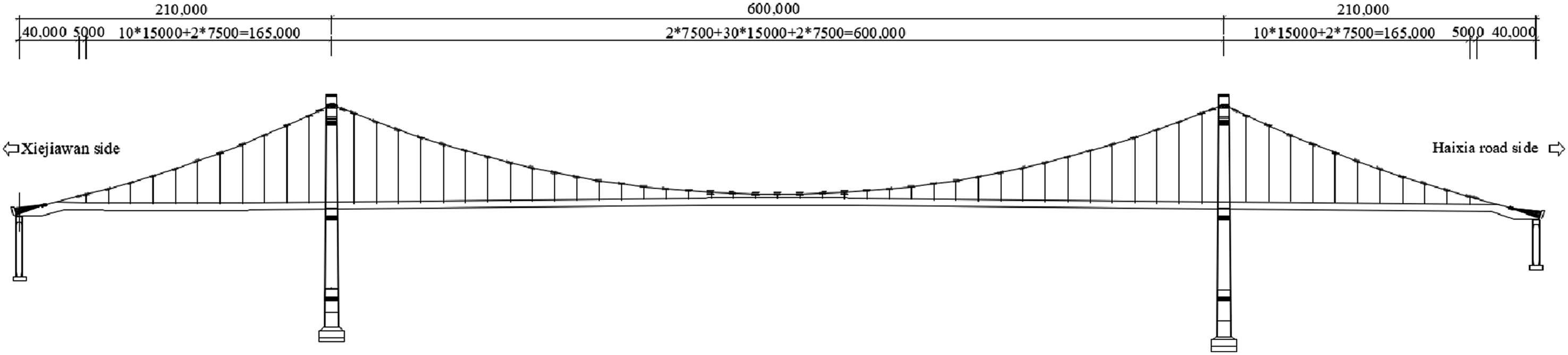
Finite element model verification
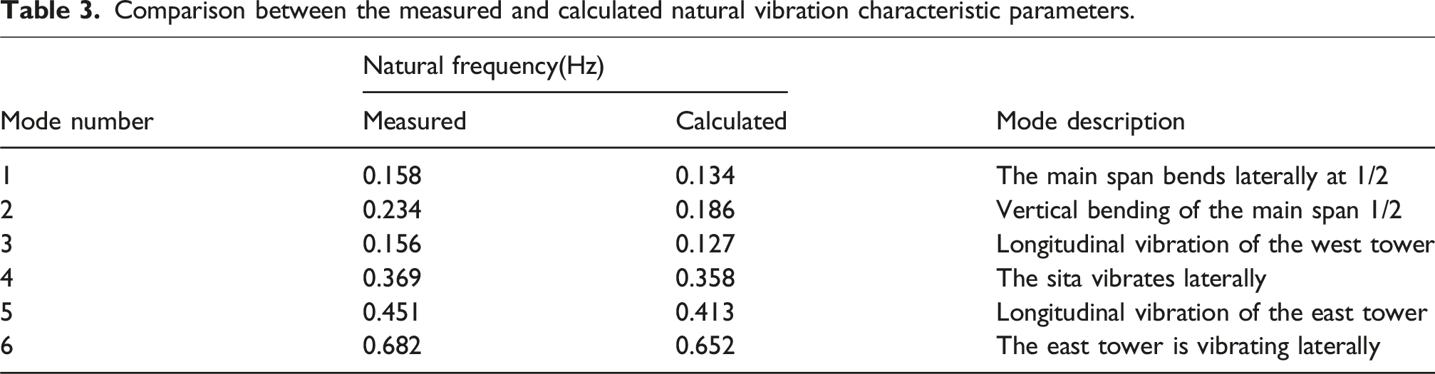
Self-vibration characteristic is one of the important dynamic response characteristics of suspension bridges. Based on the finite element analysis model of the Chongqing Egongyan Rail-transit Bridge, the natural vibration characteristics of the bridge were analyzed. The first-order and second-order vibration modes are shown in Figure 7. The characteristic parameters of the bridge were obtained based on the on-site environmental vibration test. The comparison between the measured values and the calculated values is shown in Table 3. It can be seen that the modal parameters measured by the environmental vibration test are in good agreement with those calculated by the finite element method. This finite element model can serve as the baseline model for further dynamic response analysis of the bridge. The first and second-order vibration mode shapes obtained from finite element analysis. Comparison between the measured and calculated natural vibration characteristic parameters.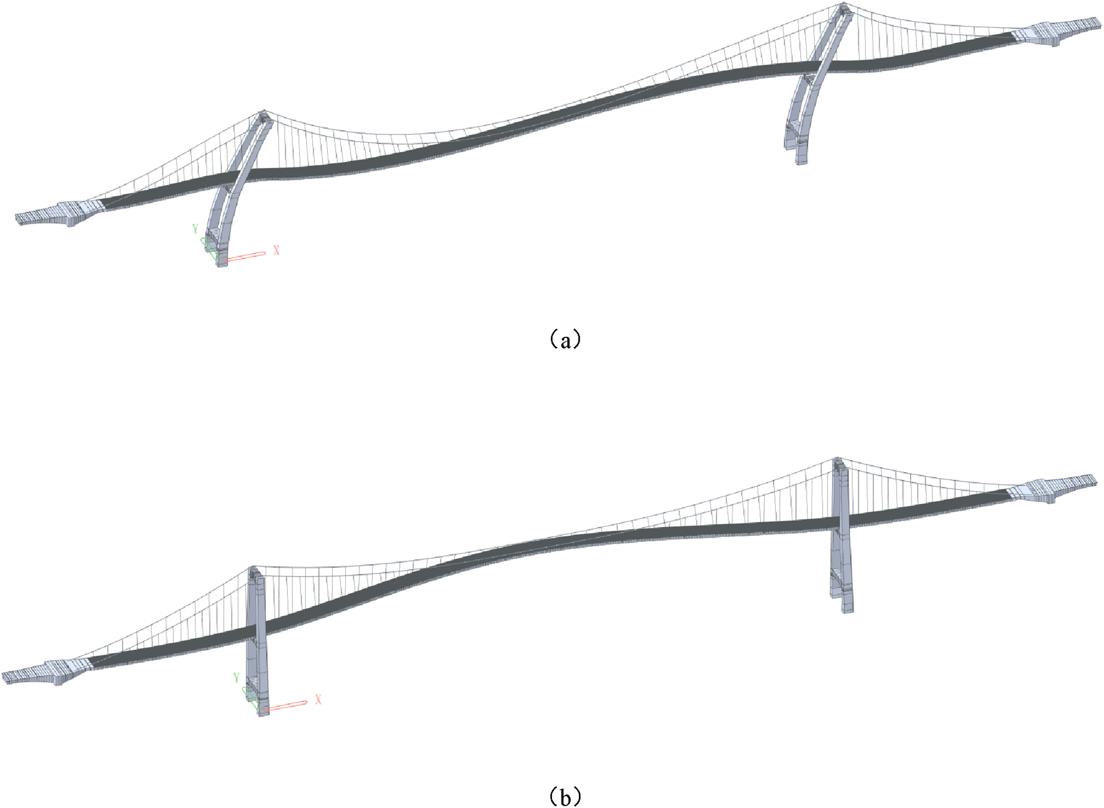
Vertical deformation limit analysis
The vertical deformation of long-span steel box self-anchored track suspension bridges is mainly caused by train loads and temperatures, and the vertical deformation is closely related to the radius of curvature of the bridge. The smaller the radius of curvature, the greater the centrifugal force generated when the train passes through, and the more obvious the deformation of the track structure, which in turn leads to an increase in the vertical acceleration of the train and affects the smoothness of operation. Meanwhile, a larger vertical acceleration will also cause more dynamic impacts on the bridge structure, accelerating its fatigue damage.
Therefore, to ensure the comfort and safety of train operation, based on the concept of centrifugal acceleration in the “Code for design of railway tracks” 25 and the operational performance control limits proposed in “Operational performance analysis indicators,” the corresponding radius of curvature limits are determined. When the minimum radius of curvature of the initial deformation curve of the bridge deck reaches this limit value, it is the initial deformation limit value of the bridge deck. On this basis, the initial deformation and the deformation under the action of train load are superimposed. Through the vibration analysis of vehicle-bridge coupling, the maximum safety control value of vertical deformation is determined based on the principle that the vertical acceleration of the train reaches or approaches the control limit.
Therefore, when exploring the operational limits of this type of bridge and studying its vertical deformation limit, the specific steps are as follows: Firstly, determine the minimum radius of curvature based on the control limit of the train’s vertical acceleration, thereby clarifying the initial deformation limit; Then, through the analysis of the initial deformation and the deformation under the action of train load, the control value of the maximum vertical deformation is proposed. Finally, the deformation grading control limit is determined through vehicle-axle coupling vibration analysis. If necessary, this limit can be modified. The specific steps are shown in Figure 8. Analysis flow of permanent deformation control limit of long-span track concrete cable-stayed bridge.
Based on vehicle-bridge coupling, determination of train vertical acceleration control limit a, vertical acceleration a2 corresponding to bridge deck initial deformation, and minimum curvature radius r
Maximum value of train response calculation and analysis evaluation.
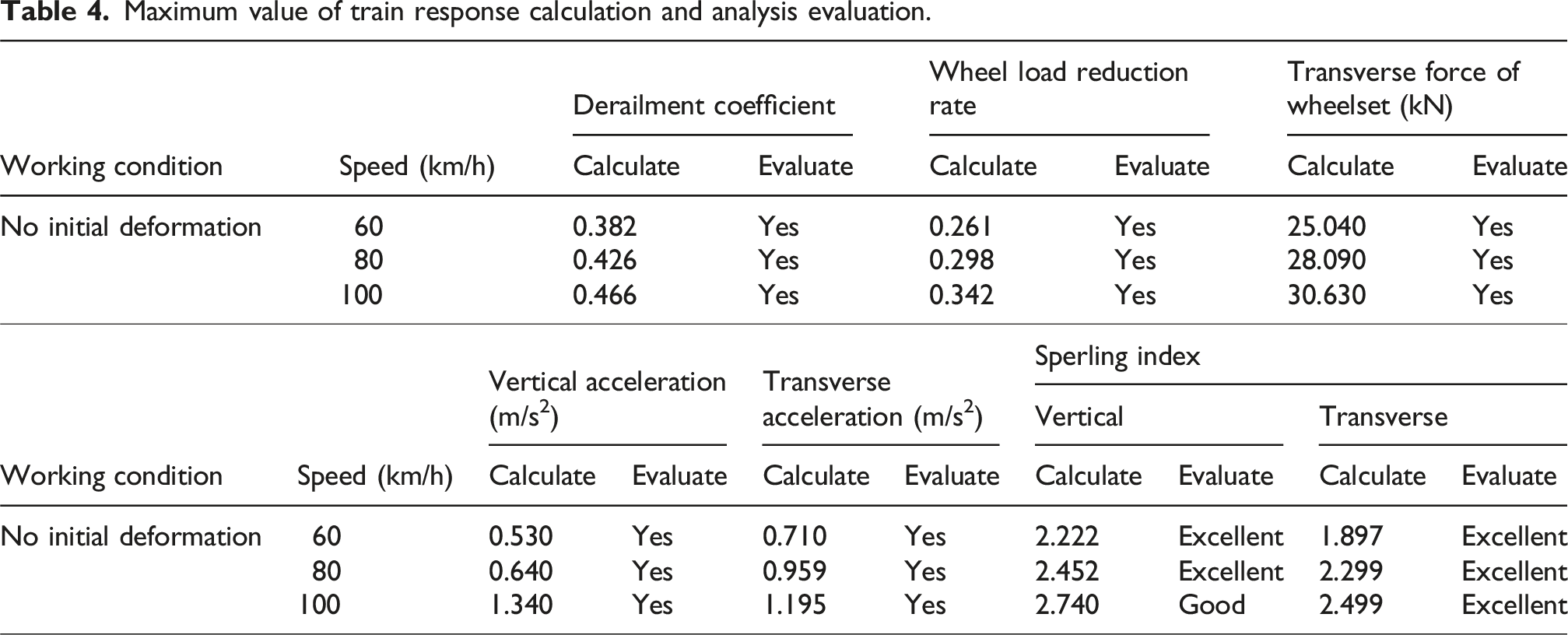
As can be seen from Table 2, the operational safety index, vertical acceleration index and lateral acceleration index are all within the control limits, and the Sperling index is in the “excellent” and “good” states, meeting the operational performance requirements. Thus, taking 100 km/h as the design speed limit, the vertical acceleration of the vehicle body without initial deformation is
Analyze the deformation curve of the bridge and determine the position of the most unfavorable working condition
Because longitudinal viscous dampers are set between the tower beams of the Chongqing Egongyan Rail-transit Bridge, it can be regarded as a longitudinal floating system under temperature load. The deformation curve of the bridge under the overall rising and cooling action is small, and the curvature radius is large, so it is not suitable to determine the vertical stiffness limit as a calculation condition alone. Therefore, the temperature deformation is considered as the inherent initial deformation when analyzing the vertical stiffness limit of suspension bridges. First, the vertical deformation of the bridge was calculated under two conditions of temperature rise of 25°C and a temperature drop of 20°C, and the results are shown in Figure 9. Vertical deformation curve of bridge under temperature load; (a) Bridge deformation curve with overall temperature rise of 25°C; (b) Bridge deformation curve with overall cooling of 20°C.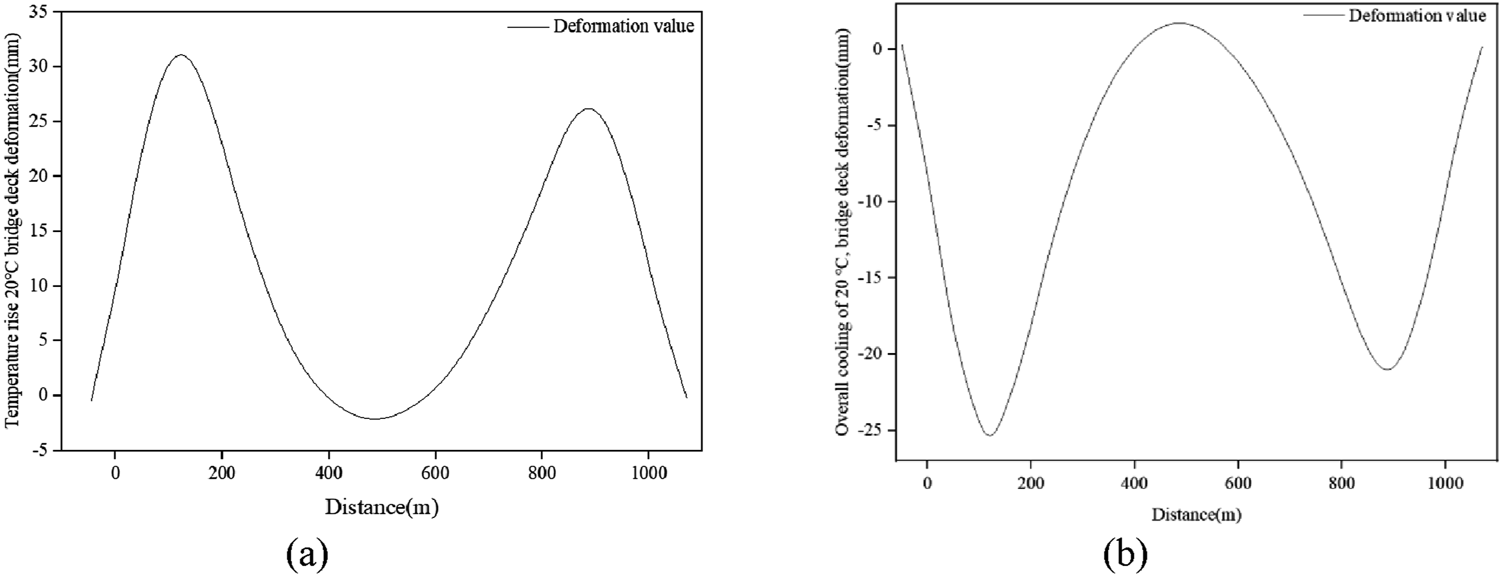
As can be seen from Figure 9, under the heating state, the maximum vertical displacement of the bridge deck is 31.699 mm, and according to the minimum radius of curvature, it is 17,128.6 m. Under the cooling condition, the maximum vertical displacement of the bridge deck is 25.377 mm, and the minimum radius of curvature is 2,476.5 m, both located at the auxiliary pier position. Meanwhile, the mid-span vertical displacement generated by the single-track 6-car A-type track train is 351.28 mm. The maximum vertical displacement of the bridge deck caused by temperature loads is only 31.699 mm (for temperature rise) and 25.377 mm (for temperature drop), which is much smaller than the mid-span displacement (351.28 mm) caused by train loads. The minimum radius of curvature corresponding to temperature deformation is relatively large, indicating that the bridge deck bends gently and has a weak dynamic impact on train operation. Therefore, the deformation under temperature loading can be regarded as the initial deformation, and its magnitude and influence will not significantly interfere with the dynamic response analysis dominated by train loads, thereby verifying the feasibility of considering the deformation under temperature loading as the initial deformation.
Then, to comprehensively assess the influence of different load distribution patterns on bridge deck deformation, two typical working conditions, namely the uniform load of the entire bridge and the uniform load of the middle span, were selected for comparative study. Among them, the uniform load across the entire bridge simulates the extreme scenario where the entire span of the bridge, including the middle span, side span, and auxiliary piers, is uniformly loaded, reflecting the response characteristics of the “overall coordinated deformation” of the structure. The uniformly distributed load at the mid-span focuses on the working conditions where the mid-span is locally loaded, verifying the inhibitory effect of the side span constraints on the mid-span deformation, and comparing the deformation differences between local and overall loading. Based on the equivalent uniform live load standard of metro trains in the “Code for design of urban rail transit bridge,” and in combination with the span and axle load characteristics of this bridge, the load concentration for both types of working conditions was taken as 10 t/m, and the vertical displacement of the bridge deck was calculated. The results are shown in Figure 10. Vertical deformation curves of the bridge under different load conditions; (a) The deformation curve of the bridge under the load of 10 t/m is distributed throughout the bridge; (b) the Deformation curve of the bridge under uniform 10 t/m load at mid-span.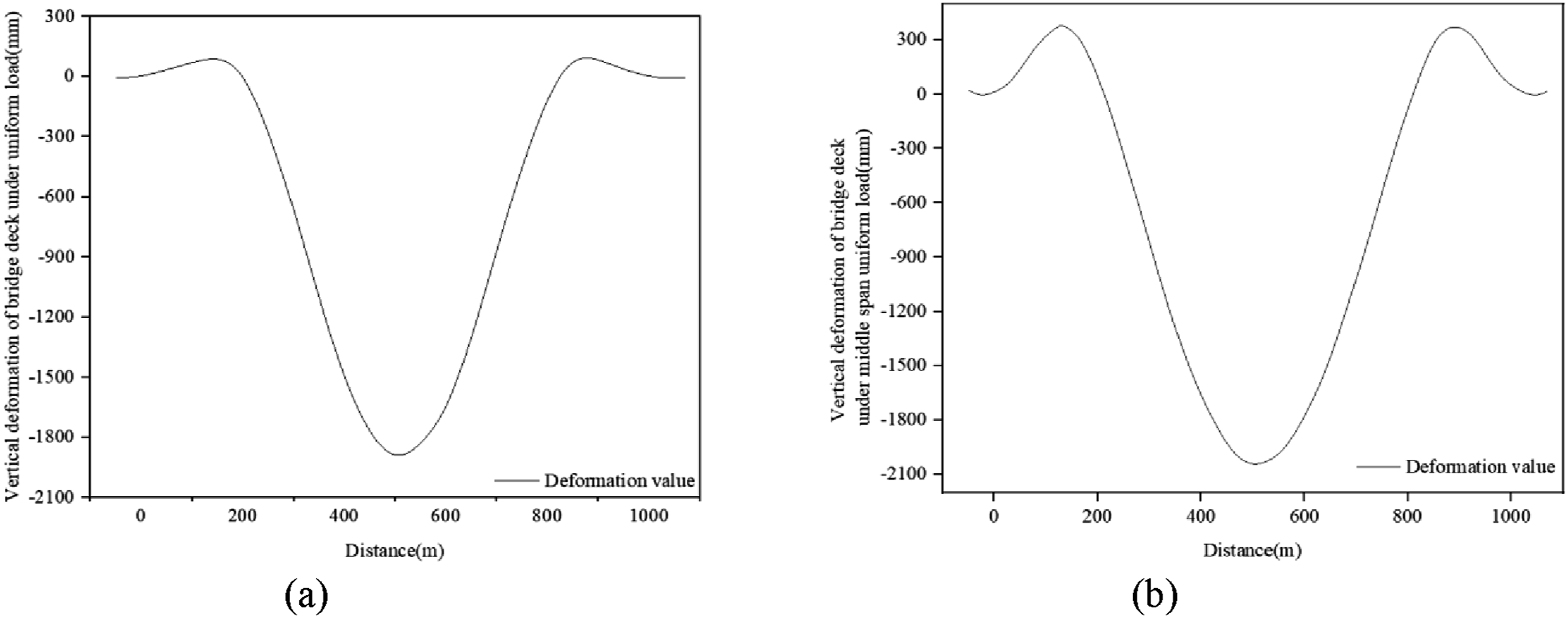
Based on the vertical deformation curves of the bridge deck under different load conditions in Figure 10, the position diagrams of the minimum radius of curvature for the vertical deformation of the bridge deck under each condition were calculated. The results when the torsion ratio of the middle span is L/2000 were extracted from it: The condition of uniform load throughout the bridge is the most unfavorable, with a minimum radius of curvature of 2446 m, and the condition of uniform loading in the middle span has a minimum radius of curvature of 8114 m. The results are shown in Figure 11. Schematic diagram of the minimum curvature radius of vertical deformation of bridge deck under different load conditions; (a) The position of the minimum curvature radius of bridge deformation under the uniform load of the whole bridge; (b) The position of the minimum curvature radius of bridge deformation under the middle span uniform load.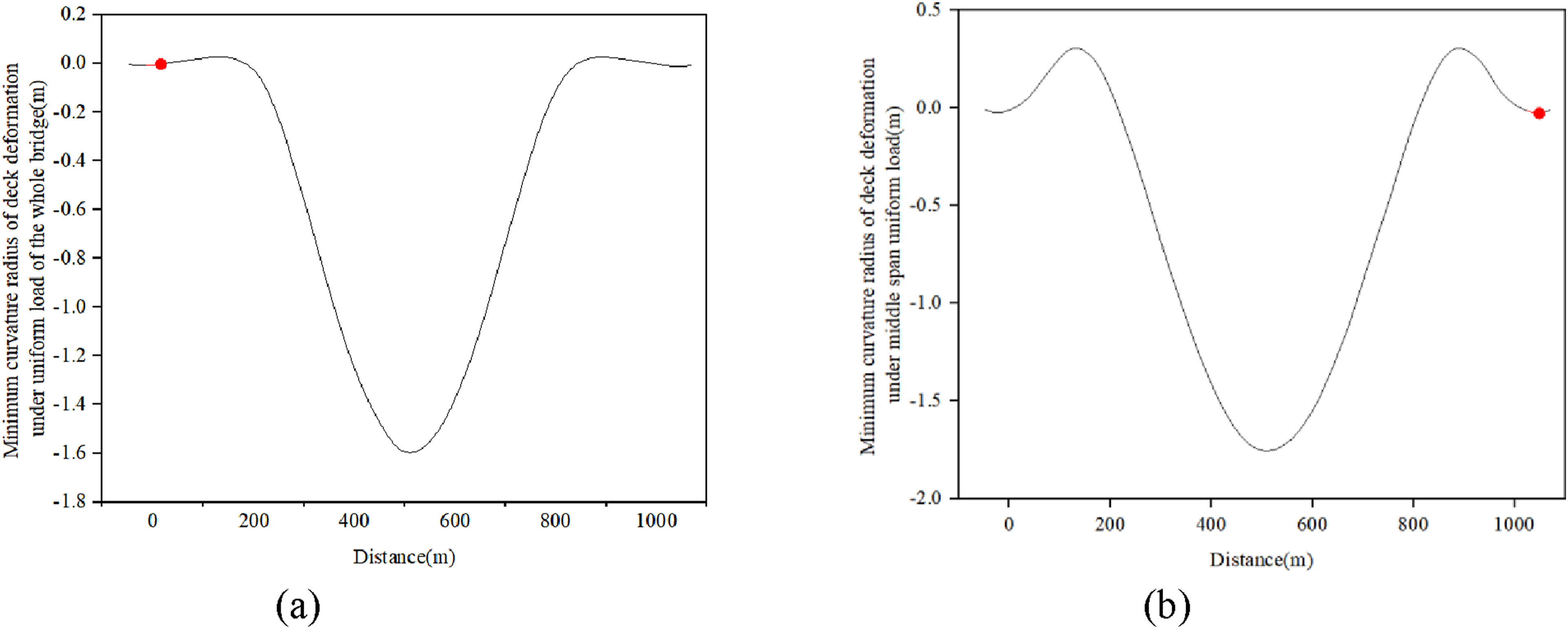
Determine the initial deformation curve of the bridge deck, and determine the safety control value of the maximum vertical displacement initially
Therefore, according to the initial deformation curve of the bridge corresponding to the uniform load condition of the whole bridge, the amplitude is adjusted, and the final initial deformation curve of the bridge under the condition of cooling 20°C is superimposed.
When the minimum curvature radius reaches the limit value, the limit value of bridge deformation is preliminarily determined, which is included in the train load action, and the vehicle-bridge coupling dynamic analysis is carried out. The vertical stiffness limit value is preliminarily proposed on the principle that the acceleration of the vehicle body meets the comfort standard or the ride comfort standard meets the qualification standard, and the obtained vertical stiffness limit value is the total flexural span ratio L/500.
Based on the reasonableness of the maximum vertical deformation safety control value verified by vehicle-bridge coupling, the maximum vertical deformation safety control value and early warning control value were determined
Calculation conditions and description.
Maximum calculated value and analysis evaluation of train response when the maximum vertical deformation safety control value is L/500.
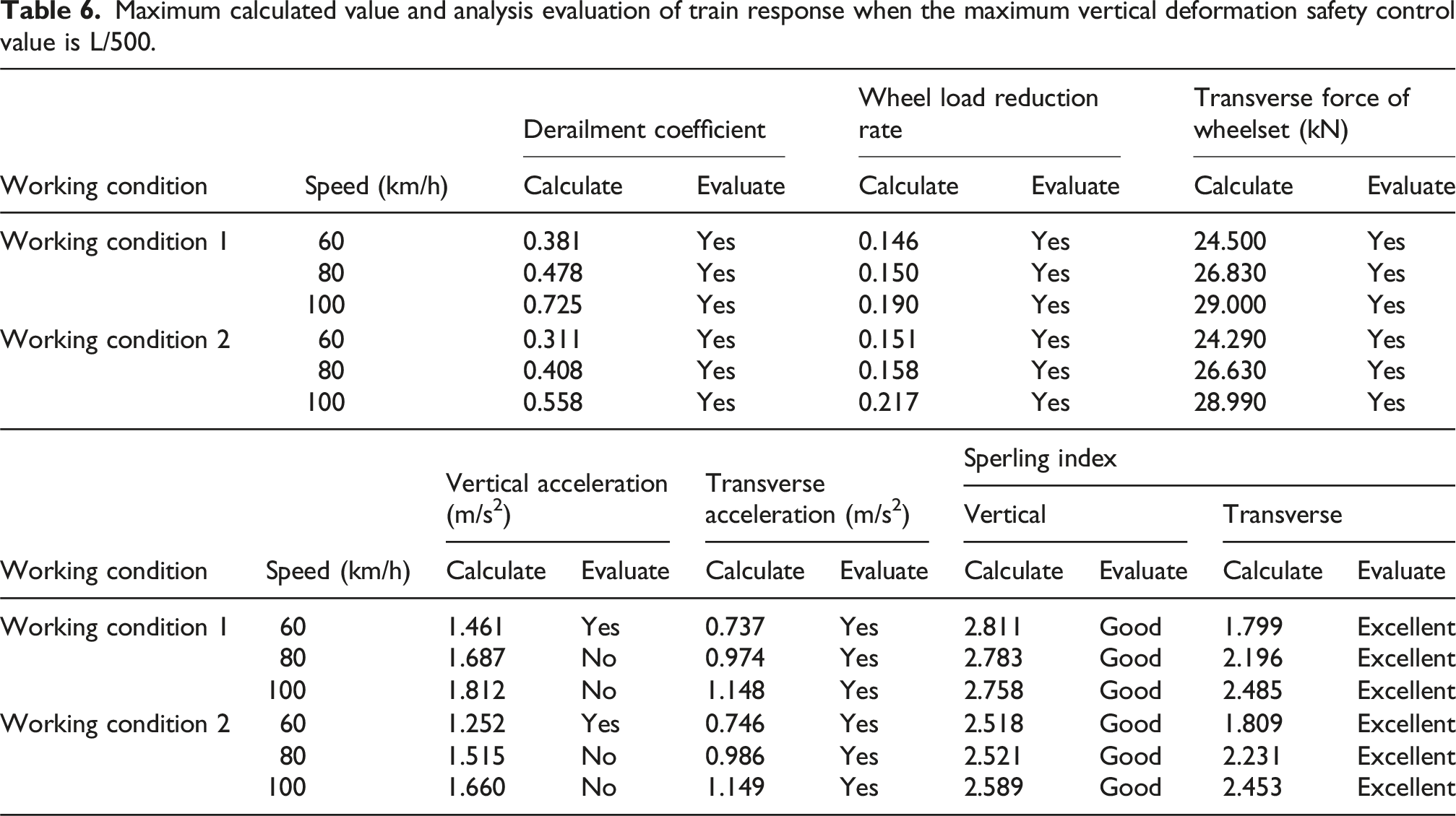
As can be seen from Table 6, according to the analysis results of vehicle-bridge coupling vibration, under the two working conditions, the maximum derailment coefficient is 0.725, the maximum wheel weight load reduction rate is 0.217, and the maximum transverse force of wheelset is 29.000 kN. The maximum vertical acceleration is 1.812 m/s2, exceeding the comfort standard of 1.5 m/s2, and meeting the emergency repair standard of 2.0 m/s2. The Sperling index has reached 2.758 (vertical), which is in the “good” range, so it is reasonable to take L/500 as the maximum vertical deformation safety control value. According to Reference 26, the maximum vertical deformation early warning control value is L/600 when a safety factor of 1.25 is taken into account. 26
Real bridge verification
Structural deformation monitoring system
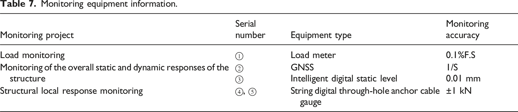
The structural deformation monitoring system of the Chongqing Egongyan Rail-transit Bridge mainly consists of the following five parts: ① Moving load monitoring, ② spatial deformation of the main bridge, ③ vertical deformation of the stiffening beam, ④ main cable force, and ⑤ suspension cable force. The long-term health monitoring system mainly consists of five major systems, namely the sensor subsystem, the data acquisition and transmission subsystem, the data processing and analysis subsystem, the data storage and management subsystem, and the early warning subsystem. The sensor system collects structural response data through on-site sensors and uploads it to the system platform via the transmission system. And data processing, analysis, and storage are carried out on the platform. Once the limit value is exceeded, a timely warning will be issued. The overall layout of the structural deformation monitoring system for the Chongqing Egongyan Rail-transit Bridge is shown in Figure 12, and the information of the monitoring equipment is presented in Table 7. The overall layout of the structural deformation monitoring system for the Chongqing Egongyan Rail-transit Bridge. Monitoring equipment information.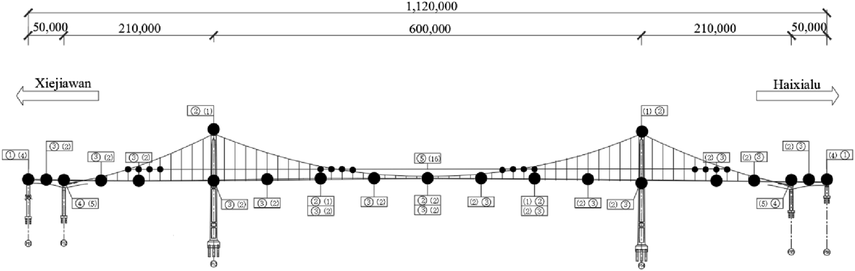
Verification of early warning control value
Since December 30, 2019, the Chongqing Egongyan Rail-transit Bridge has been put into use, it has been running smoothly for 5 years. To verify the indicators proposed in this study, the vertical deformation data of the main beam at L/2 of the upper and lower reaches of the main beam span from December 1, 2024, to December 30, 2024, were obtained through the health monitoring system of Chongqing Egongyan Rail-transit Bridge. The results are shown in Figures 13 and 14. Vertical displacement at L/2 of the middle and higher reaches of the span from 2024.12.1 to 2024.12.1. Vertical displacement at L/2 of the middle and lower reaches of the span from 2024.12.1 to 2024.12.1.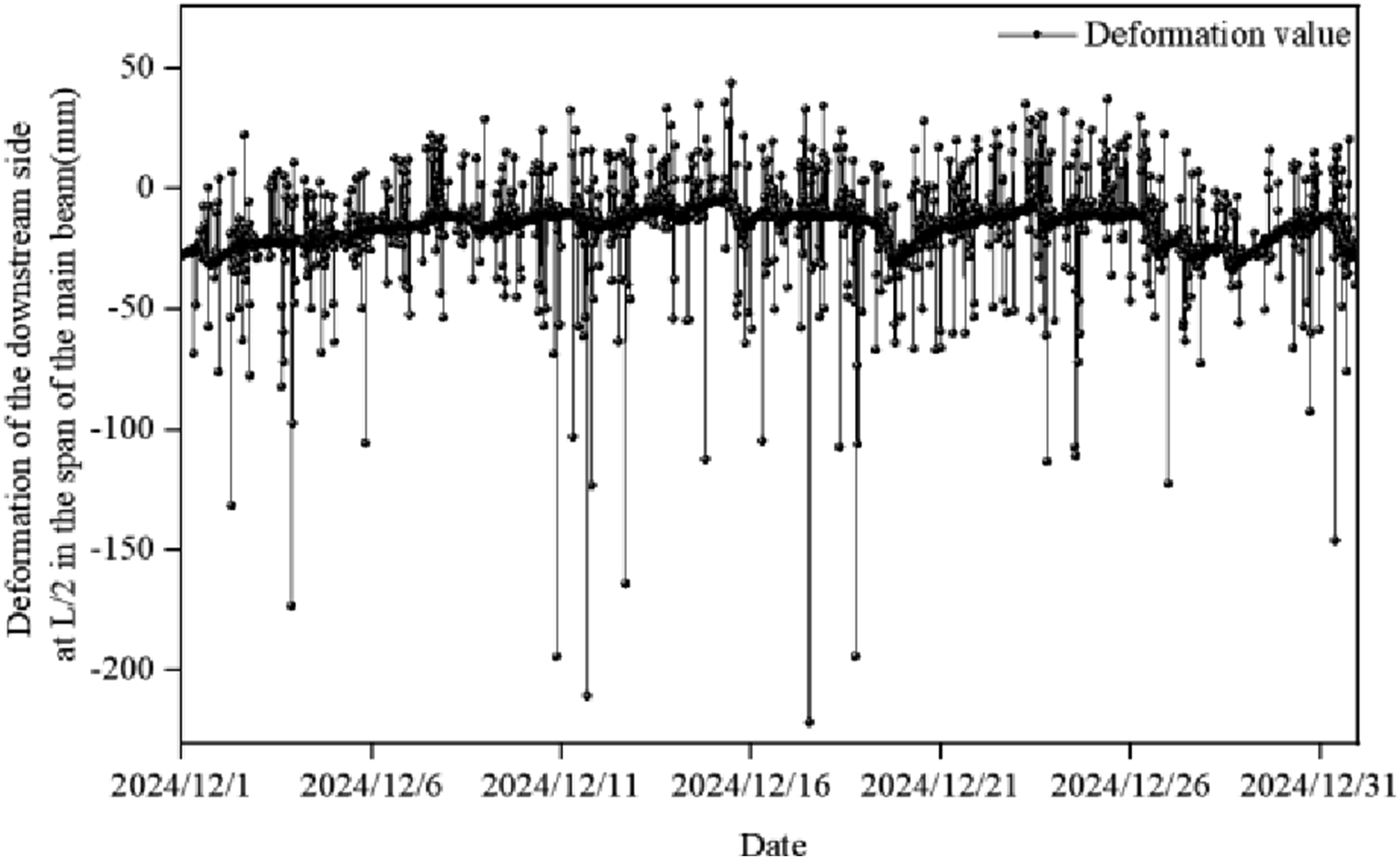
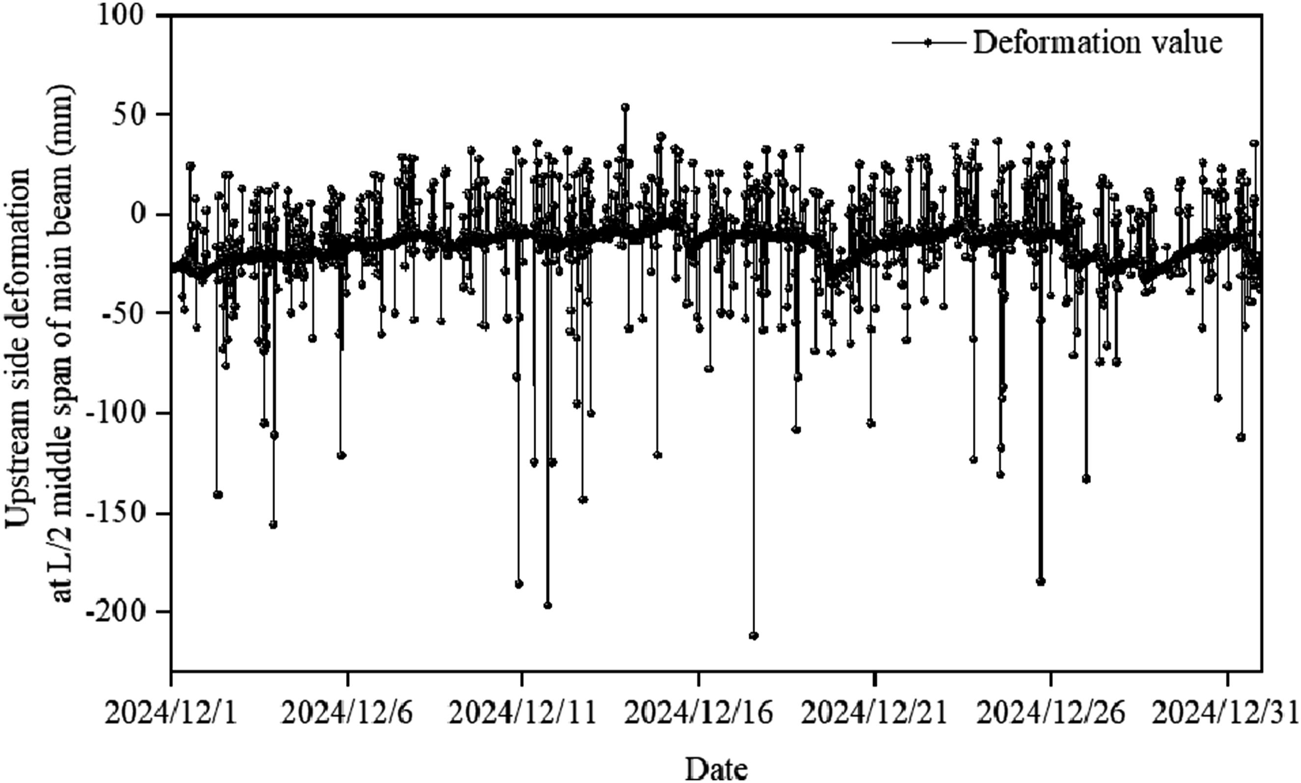
It can be seen from Figures 13 and 14 that during the period from December 1, 2024, to December 31, 2024, the bridge is in normal operation and maintenance condition, and the maximum upstream and downstream deformation values at the middle span of the Chongqing Egongyan Rail-transit Bridge are 211.4 mm and 221.6 mm, respectively, meeting the requirement of less than
Discussion
Compared with the provisions of Article 7.3.2 of “Technical specifications for operation monitoring of urban rail transit facilities - Part 2: bridges”: The early warning value for vertical deformation control is the same, both being L/600, 27 while the safety value stipulated in the specification is L/450, which is slightly larger than the calculation result L/500 in this study.
This is because the current norms are aimed at track suspension Bridges, while the research object of this paper is the large-span steel box self-anchored track suspension bridge. This type of bridge has its unique characteristics, such as: the force characteristics of its main cables and towers are different from those of traditional suspension Bridges. The self-anchoring method of the main cables makes the deformation distribution of the structure under vertical loads more complex. The cross-sectional characteristics of large-span steel box girders make them more prone to significant vertical deformation under local loads.
Second, the construction process and operational environment of this type of bridge have a more significant impact on vertical deformation. Therefore, it is necessary to re-evaluate the control limit of vertical deformation based on its own characteristics, so as to obtain a more practical limit of L/500.
In addition, in previous studies, the minimum radius of curvature method was usually adopted to initially determine the vertical deformation value. This method can provide a relatively conservative lower limit value, ensuring the safety of the structure under extreme conditions. Although this method was also adopted in this paper and the calculation result was L/500, in actual engineering, the vertical deformation control of Bridges needs to strike a balance between safety and economy. Excessively high safety values may lead to overly conservative designs and increase engineering costs. However, an excessively low warning value may prevent potential safety hazards from being detected in a timely manner. The L/500 limit proposed in this paper is more applicable in practical engineering.
Furthermore, the L/500 limit proposed in this paper lies between the normative warning value L/600 and the safety value L/450, which not only meets the minimum requirements of the specification but also avoids overly conservative design. This balance can effectively control engineering costs while ensuring the safe operation of Bridges. Finally, the L/500 limit value calculated by the minimum radius of curvature method in this study is based on actual engineering conditions and structural characteristics, which can more accurately reflect the vertical deformation of the bridge during operation. This method takes into account the actual force state and geometric characteristics of the bridge, and is more targeted compared with the current code provisions.
In conclusion, the vertical deformation control limit of L/500 proposed in this paper, while meeting the requirements of the specifications, comprehensively considers safety and economy and is derived through a reasonable calculation method, thus demonstrating stronger adaptability and scientificity. Therefore, this limit value is more suitable for the vertical deformation control of large-span steel box self-anchored track suspension Bridges under the action of trains.
Conclusion
To ensure the structural safety and operational performance of long-span steel box self-anchored track suspension Bridges, based on investigation and analysis of domestic and foreign norms and standards, combined with the coupling vibration theory of the axle and the track irregularity theory, this research analyzes its operational behavior control indicators, deduces the maximum vertical deformation safety control value and early warning control value in the operation stage, and applies them to engineering examples. It provides scientific and technical support for the safe and stable operation of the long-span steel box self-anchored track suspension bridge. The conclusions and suggestions are as follows. (1) The control limits of operation performance indicators can be implemented according to “vertical acceleration is 1.5 m/s2, lateral acceleration is 1.2 m/s2, the Sperling index is characterized by excellent, good and qualified, derailing coefficient is 0.8, wheel weight load reduction rate is 0.6, and wheelset lateral force is 60 kN.” (2) Vertical deformation has a serious impact on the alignment and operation performance of bridge structure, and the adjustment range of ballastless track fasteners of a long-span steel box suspension bridges is limited, so it is necessary to effectively set the deformation control value level. (3) Based on vehicle-bridge coupling analysis, the maximum vertical deformation safety control value in the operation stage is obtained as L/500, and the maximum vertical deformation safety early warning control value in the operation stage is obtained as L/600 when the safety factor 1.25 is included. The practical bridge test proves that the bridge operation safety classification evaluation index proposed in this paper is feasible and effective. It can provide technical support for the safety and comfort of the train while ensuring the safety and comfort of the train. (4) In the operation process of a long-span steel box self-anchored track suspension bridge, the main beam will be warped under the action of train, temperature, and other loads, which has a great impact on structural safety and operational comfort. Therefore, in the operation stage, it is necessary to set reasonable limits and strengthen safety monitoring to make corresponding decisions for the grading evaluation of operational performance.
Footnotes
Funding
The authors disclosed receipt of the following financial support for the research, authorship, and/or publication of this article: This work was supported by the China First Highway Engineering Co. R&D project (2024-B-22).
Declaration of conflicting interests
The authors declared no potential conflicts of interest with respect to the research, authorship, and/or publication of this article.
Data Availability Statement
All the data and models that were generated or used during the study are available from the corresponding author by request.