
Abstract
Acoustic black hole (ABH) has aroused increasing attentions due to its flexible broadband wave manipulation capability, but its low-frequency effect still needs to be improved. Besides, efficient dynamical calculation methods for complex ABH structures are still lacking. This article proposed a gradiently embedded ABHs-DVAs metastructure for low-frequency broadband vibration isolation based on combined broadband wave concentration of ABHs and flexible frequency tunings of dynamic vibration absorbers (DVAs). The Reduced Multibody System Transfer Matrix Method was applied with enhanced computation efficiency for metastructure modelling. Results show that the metastructure could combine the advantages of ABHs and DVAs, significantly reduce all low-frequency formants, and effectively improve the low-frequency broadband vibration isolation performance. The proposed method and vibration isolation effect were validated by finite element method and experimental results. This paper thus provides both an efficient computation method and a broadband low-frequency vibration isolation strategy for complex ABH isolation structures.
Keywords
Introduction
Vibration isolation is an important means of vibration control. For passive vibration isolation, the dissipation of mechanical vibration energy mainly relies on damping in the passive vibration isolation system, 1 therefore, in passive isolation systems, damping elements play a crucial role. However, due to the inability to adjust the parameters of components such as springs and dampers in the system structure according to changes in external excitation, excessively high stiffness will shorten the isolation frequency band, while excessively low stiffness will weaken its load-bearing performance. In addition, damping plays a role in suppressing vibration in the effective isolation band, but reduces the isolation efficiency within the ineffective isolation band, which makes traditional isolation techniques inadequate in dealing with such conflicts.
Acoustic black hole structure 2 is a new type of bending wave modulation technology.2,3 It changes the structural impedance by adjusting the thickness or material properties of the structure, which in turn compresses the wavelength of bending waves and reduces the wave velocity. 4 When the speed of the wave is reduced to close to zero, the bending wave cannot be transmitted to reach the wedge end of the structure, and will be hardly reflected, and thus the energy of the bending wave is concentrated at the edges of the structure, 5 creating the “acoustic black hole” effect.6–8 If the ABH wedge is embedded inside the structure, the vibrational energy would be concentrated around the ABH and is difficult to transmit to the edges of the structure. 9 In addition, embedding multiple ABHs in the structure can produce a stronger energy concentration, resulting in a greater loss of transmitted vibrational energy.10–12 Besides, as ABH could be regarded as broadband or multi-modal local resonators, the vibration concentration and damping enhancement occurs mainly in the vicinity of the local resonance frequencies. Hence it is natural for an ABH as a vibration isolator to avoid introducing too much damping in the non-resonant/ineffective isolation frequency bands, thus avoiding the degradation of isolation efficiency in these bands. 9 However, due to the existence of a threshold frequency for the ABHs, this isolation effect plays a major role when the radius of the ABH is greater than or on the order of the incident wavelength (i.e., above a threshold frequency). 10 This makes the use of small-sized ABH structures for low-frequency vibration isolation ineffective.
The dynamic vibration absorber (DVA), as a typical passive vibration control device, can be attached as a substructure to the position of the maximum amplitude of the main vibration system when the vibration response of the main vibration system is too large. The vibration can be controlled by absorbing/transferring vibration energy from the main vibration system to the DVA. 13 Bakre et al. 14 effectively reduced the seismic response of piping systems in industrial facilities by utilizing the high energy dissipation or damping capacity generated through stable yielding deformation of an X- plate damper. Pisal et al. 15 investigated the effectiveness of a tuned mass friction damper, which combines the linear stiffness of traditional tuned mass dampers and the nonlinear energy dissipation characteristics of friction dampers, in suppressing the dynamic response of structures. Through parametric optimization, efficient control of structural vibrations was achieved. Properly adjusting the parameters and mounting position of the DVA can create a coupling effect between the main vibration system and the DVA,16,17 thereby achieving significant vibration attenuation effects for the main vibration system in certain specific frequency ranges.18,19
The above suggests that the ABH and DVA each exhibit their uniqueness in the vibration control performance. The ABH structure has the advantage of concentrating and controlling vibrations at broad frequency bands above its cut-on frequency.20–23 While DVA can effectively absorb vibration at any harmonic frequency or frequency bands of the main structure and with flexible mounting positions and strong designability of the controlling frequency bands. Considering the excellent performance of DVA devices in reducing low-frequency vibration due to their energy absorbing working principle, and the extraordinary characteristic of ABH structure in broadband energy concentration, combining these two structures is expected to achieve complementary advantages or a broadband low-frequency vibration reduction effect24,25 without extending the ABH’s dimension. Nevertheless, previous studies are mainly confined to vibration reduction via attaching DVA to an ABH wedge tip. To the best of the authors’ knowledge, there is still a research gap in vibration isolation using ABHs-DVAs metastructures and especially using the embedded ABHs-DVAs metastructures.
With regarding to the computation methods for ABH structures, several methods have been commonly used, including geometric acoustic method, semi-analytical method, and finite element method (FEM). For semi-infinite ABH structures, the geometric acoustic method is frequently used, which requires that the propagation of bending waves satisfy the basic assumption of geometric acoustics, 26 that is, the wave number changes sufficiently small within a distance equivalent to the wavelength. To break this, Georgiev et al.5,6,13 proposed to calculate the bending wave reflection matrix in ABH structures using the impedance matrix method. For finite ABH structures, several semi-analytical methods have been proposed to solve their structural responses27,28 using various basis functions as shape functions to fit the deflection of the structure especially at the wedge tip with rapidly varying wavelength,12,29 such as wavelet function,10,30 Gaussian basis function.31–33 Although exact analytical solutions are also developed for a thin ABH beam wedge, 21 the above methods mainly apply for simple ABH structures. For ABH structures with more complex geometries and topologies, numerical methods such as FEM are two often resorted to references 34,35, which, nevertheless, can become time-consuming for composite and complex structures. Besides, inappropriate mesh division not only reduces computational efficiency but also may lead to matrix ill conditioning problems. The classic Transfer Matrix Method (TMM) is also used as an effective computational method for investigating ABH dynamics.24,36 TMM has the advantages of flexible modeling, high computational efficiency, and not requiring the overall system dynamics equations. However, it mainly works for one-dimensional chain systems.
To deal with this, Rui et al. proposed the Multibody System Transfer Matrix Method (MSTMM) for linear multibody systems,37,38 which was first applied to the study of eigenvalues of mechanical systems such as complex multibody launch systems, solving the numerical ill-conditioning problem encountered in the calculation of the natural vibration characteristics of complex linear multibody systems and improving computational efficiency. MSTMM breakthroughs the limitations of TMM and extends it from one-dimensional chain systems to high-dimensional systems with different topological structures. It can thus handle many complex problems that TMM cannot solve, such as the dynamics of multi rigid body systems and rigid flexible coupling systems,39–41 especially problems with time-varying, nonlinear, and large motion characteristics.42–44 It has the advantages of not requiring the establishment of overall system dynamics equations, high degree of programming, low system matrix order, and high computational efficiency. 45 The Reduced Multibody System Transfer Matrix Method (RMSTMM) 46 combines the Multibody System Transfer Matrix Method with reduced transformations, retaining the fast computational advantages of MSTMM while reducing the order of the transfer matrix through reduced transformations, thereby improving numerical stability during the calculation process.47–49
In this paper, a metastructure consisting of multiple gradiently embedded ABH-DVAs, referred to as GE-ABHs-DVAs, is proposed by utilizing the broadband isolation property of embedded ABHs and the flexible frequency designability of DVAs. The steady-state response of the GE-ABHs-DVAs metastructure is calculated using the RMSTMM, and validated via using the Finite element method. Then the multi-population genetic algorithm and the fixed-points theory are used for the optimized design of the metastructures. Finally, the optimized metastructure samples were fabricated. And vibration isolation tests were conducted to verify their effectiveness in low-frequency broadband vibration isolation and the applicability and correctness of RMSTMM in calculating such complex ABH metastructures.
RMSTMM-based dynamic modelling of the GE-ABHs-DVAs metastructure
The proposed GE-ABHs-DVAs metastructure, as shown in Figure 1(a), is a complex tree multibody system consisting of a combination of multiple gradiently embedded ABHs (GE-ABHs) and multiple additional DVAs. While prior research focused on integrating DVAs into ABH wedge regions for structural vibration suppression,
24
the GE-ABH-DVA composite metastructure remains unexplored, especially in vibration isolation applications. Furthermore, although MSTMM has been utilized to analyze embedded periodic ABHs
11
and graded reinforced double-leaf ABHs,
9
RMSTMM has not been extended to vibration isolation systems, nor has it been applied to GE-ABH-DVA configurations. To simplify the analysis, take three ABHs and six DVAs as an example and the pioneered RMSTMM-based dynamic modelling is conducted for the GE-ABHs-DVAs metastructure. It should be noted, however, the modeling and analysis methods to be demonstrated is general and do not place a limit on the number of ABHs and DVAs. In Figure 1(a), LABHj is the total length of the jth ABH beam; L
j
is the total length of the jth beam; H is the thickness of the uniform section main beam; Hdj is the truncated thickness of the jth ABH (j = 1, 2, 3). A sinusoidal harmonic excitation with an amplitude of F0 is applied at the left end xs of the structure. Six single degree of freedom DVAs are located at The GE-ABHs-DVAs metastructure. (a) Structure diagram (b) topology diagram.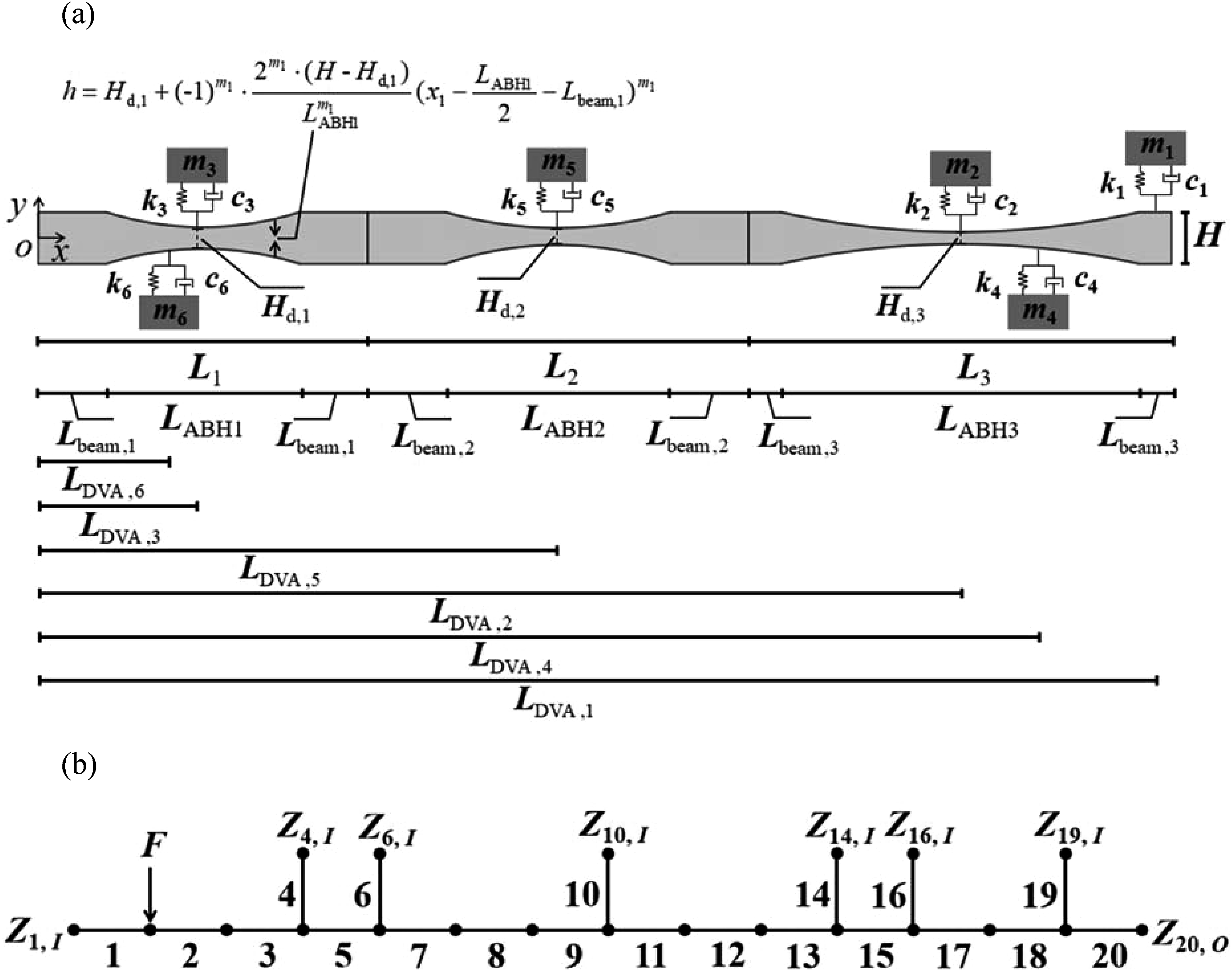
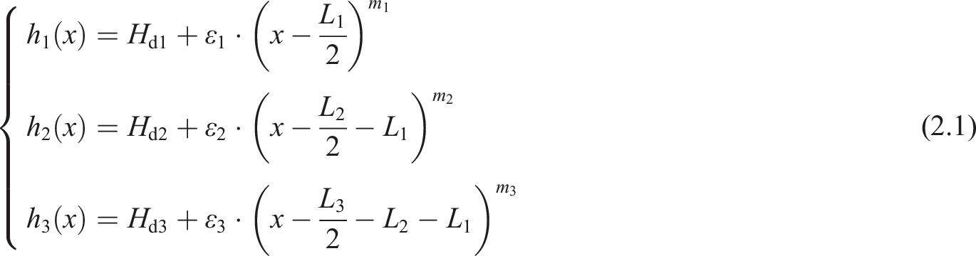
The thickness of the ABH beam satisfies the following conditions
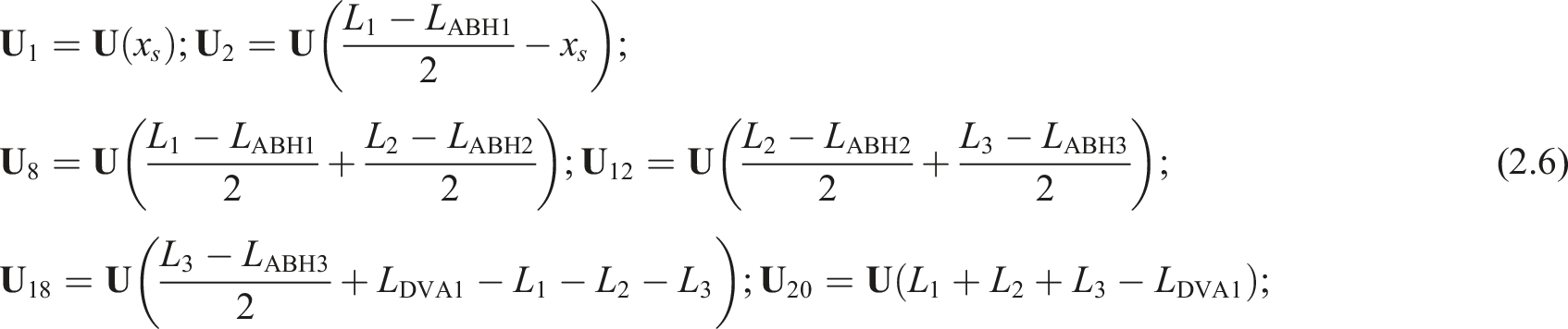
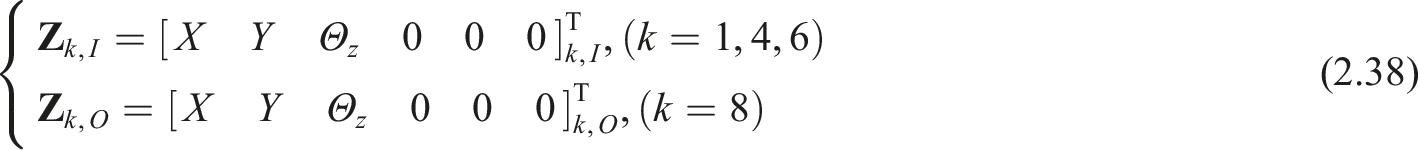
The topology diagram of the GE-ABHs-DVAs metastructure based on RMSTMM is shown in Figure 1(b), which can be categorized into unstressed uniform beam elements (elements 1, 8, 12, 18, and 20), the uniformly stressed beam elements (element 2), the ABH beam elements (elements 3, 5, 7, 9, 11, 13, 15, and 17), and the DVA elements (elements 4, 6, 10, 14, 16, and 19). The state vector of the jth element in the physical coordinates is defined as
Derivation of element transfer matrices
The uniform beam elements (elements 1, 2, 8, 12, 18, and 20) and the ABH beam elements (elements 3, 5, 7, 9, 11, 13, 15, and 17) are modeled using the Euler–Bernoulli beam model. Figure 2(a) shows a uniform Euler–Bernoulli beam with a length of x, a beam thickness of H, a beam width of D, a Young’s modulus of E, and a density of ρ. Considering the transverse bending and longitudinal vibration motion of the beam,
37
its state vector Schematic diagram of two-dimensional plane uniform Euler–Bernoulli beam. (a) Structure diagram (b) direction of state variables.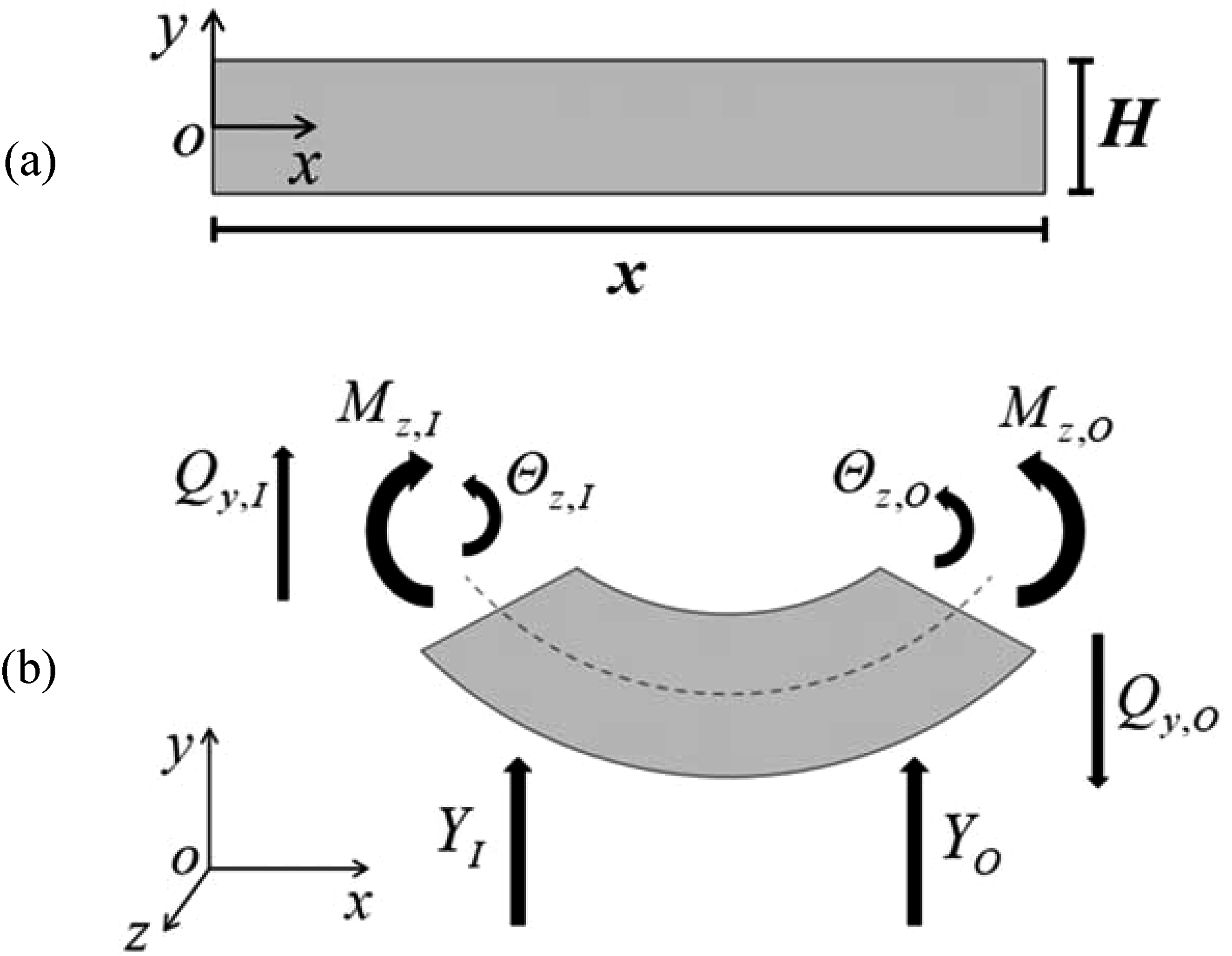

So the transfer equation of the Euler-Bernoulli beam shown in Figure 2(a) can be obtained as follows

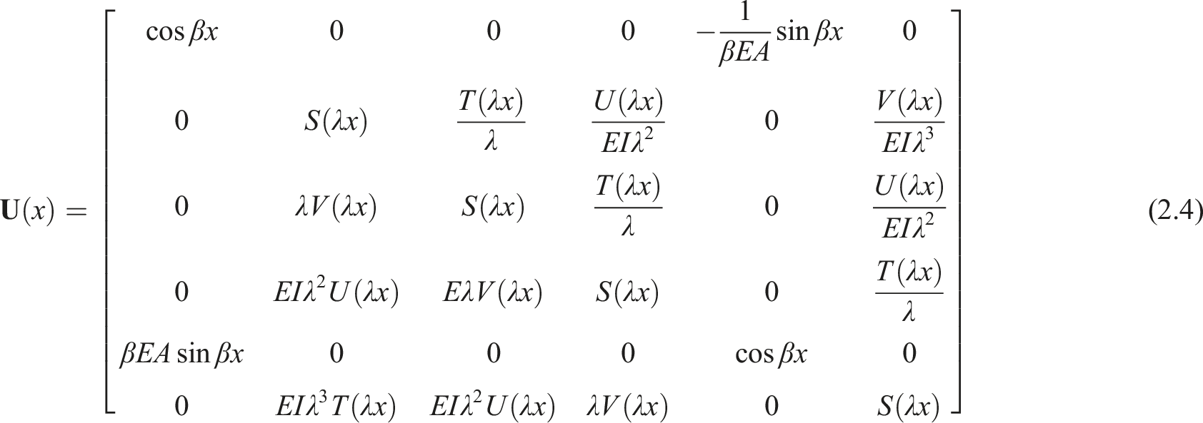
The definition of S(x), T(x), V(x), U(x) is as follows

The transfer matrix of uniform beam elements 1, 2, 8, 12, 18, and 20 can be obtained from equation (2.4) as follows
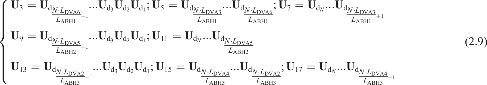
The ABH beam element (3, 5, 7, 9, 11, 13, 15, and 17), as a variable cross-section beam element, can be regarded as a multi-step beam composed of N equal-length, equal cross-section but unequal thickness micro-beams connected in sequence, as shown in Figure 3. The transfer matrix of the equal cross-section beam is used to solve this problem. The ABH beam elements. (a) Structural diagram (b) equivalent ABH beam element composed of N-section equal cross-section micro beams spliced together.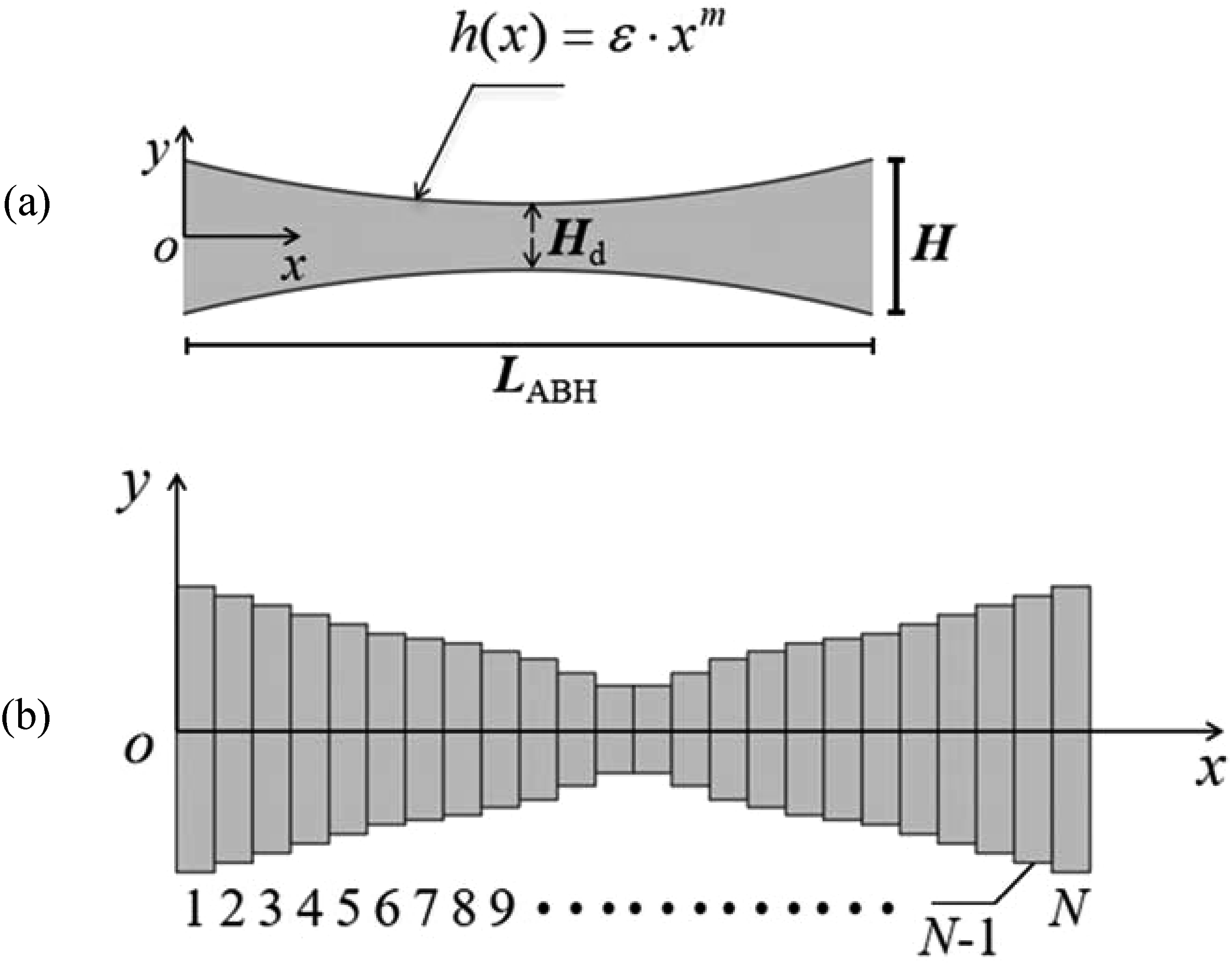
The transfer matrix of each micro beam is written as

By multiplying transfer matrices all the micro-beam segments, the transfer matrix

The transfer matrices of elements 3, 5, 7, 9, 11, 13, 15, and 17 can be obtained from equation (2.8) as follows
For the DVA elements (elements 4, 6, 10, 14, 16, and 19), the jth element is a spring-mass damper formed by a spring (with a stiffness k
j
) in parallel with a damper (with a damping coefficient of c
j
) connected in series with a mass block (with a mass of m
j
), as shown in Figure 4(a). Spring damper with an additional mass block: (a) Schematic diagram of the DVA model (b) derivation of transfer matrix for massless spring dampers (c) derivation of transfer matrix for concentrated mass block.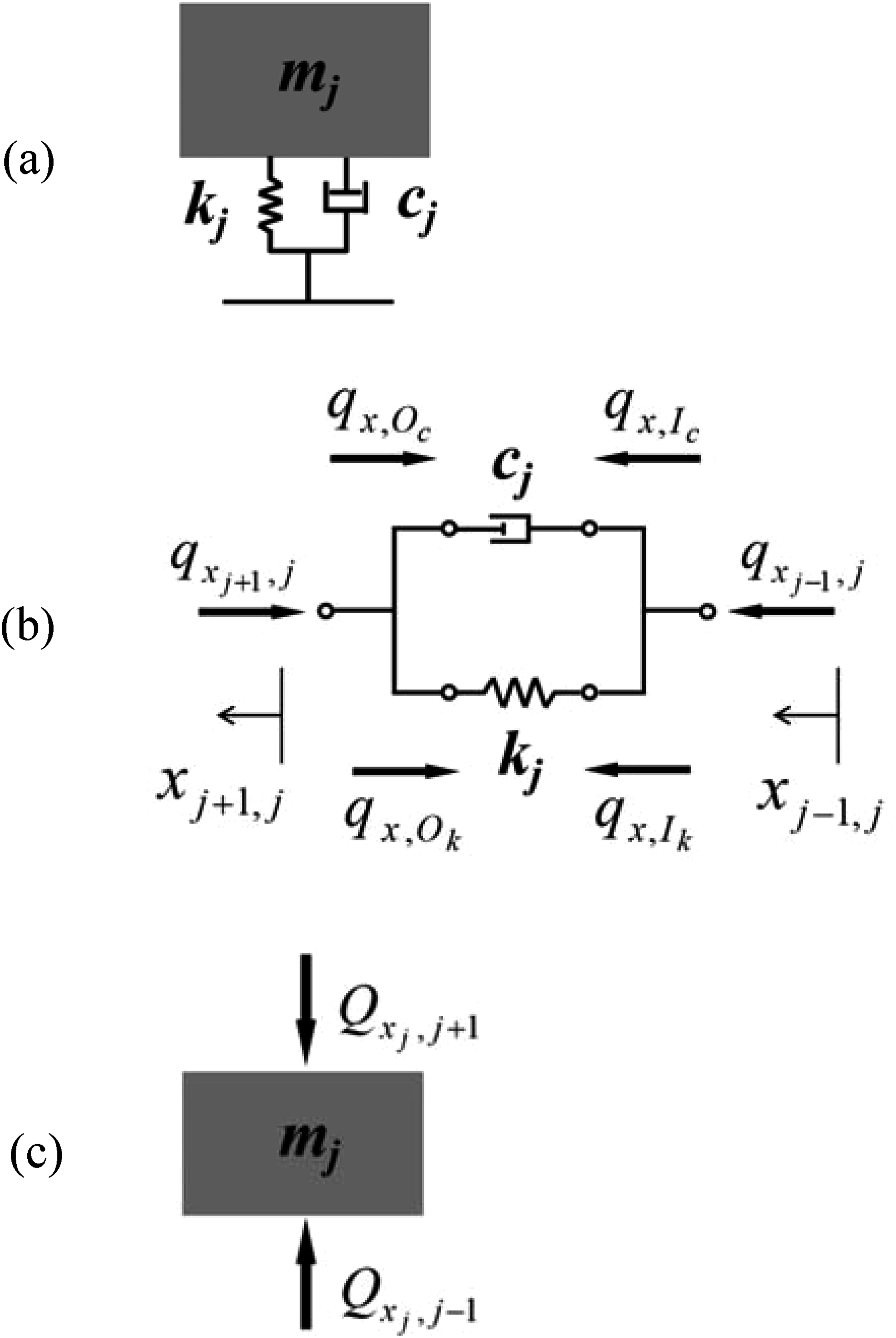
As shown in Figure 4(b), the damping force and elastic force at both ends of the massless spring damper are equal

The total internal force at both ends of the parallel spring-damper conforms to

Hence

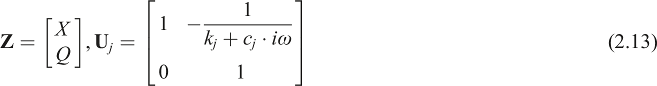
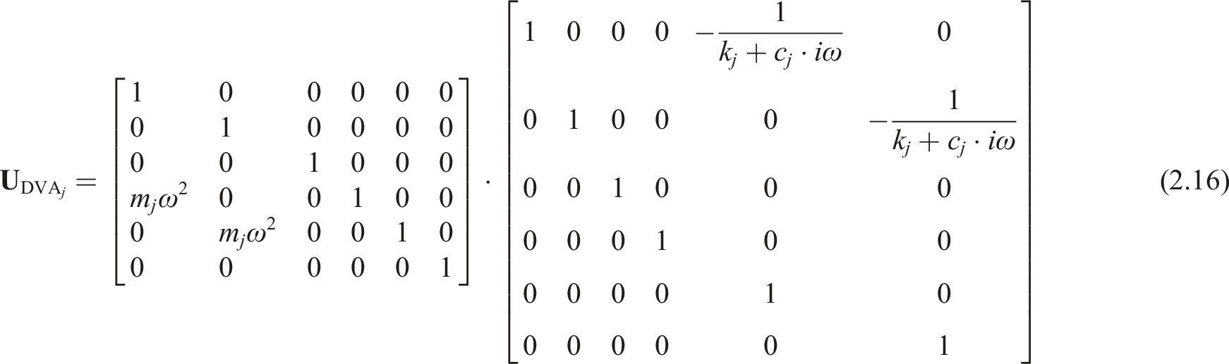
As shown in Figure 4(c), the relationship between the displacement and force at both ends of the concentrated mass block in the spring damper system is


By combining equations (2.13) and (2.15), the transfer matrix of the DVA structure shown in Figure 4(a) can be obtained as
According to equation (2.16), the transfer matrices of DVA elements 4, 6, 10, 14, 16, and 19 are

According to Figure 1(b), the coordinates of the connection nodes between each DVA and the GE-ABHs beam coincide, so the kinematic consistency equation matrix of the multi-input single-output element can be obtained as
48

Hence for any multi-input single-output element j, its transfer equation and geometric equation can be written as


Derivation of reduced transfer matrices
The RMSTMM divides the state vectors in equations (2.19) and (2.20) into blocks46,48


Introducing the reduction transformation

Substituting equation (2.23) into equations (2.21) and (2.22) yields
50

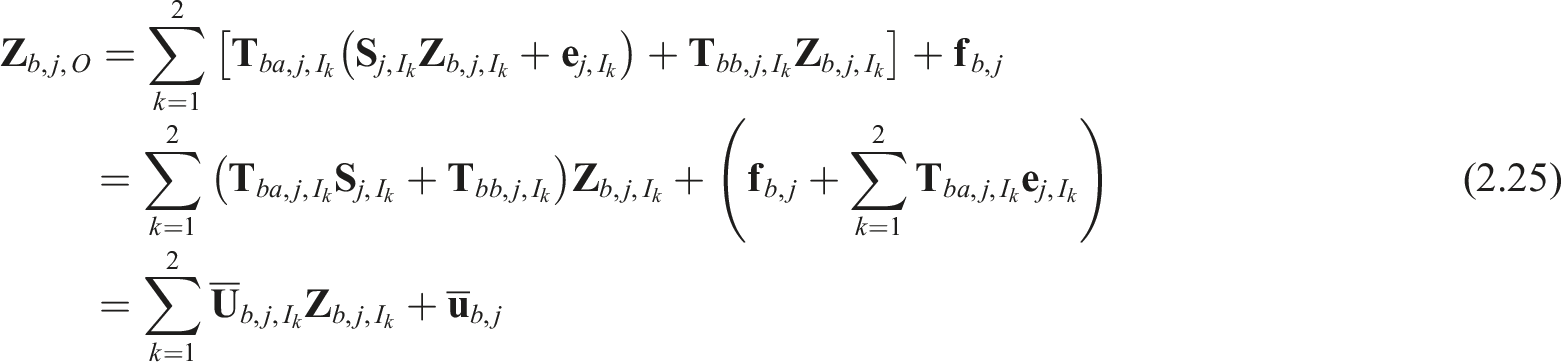


Equations (2.26) can be organized as


Substituting equation (2.29) into equations (2.24) and (2.25) yields

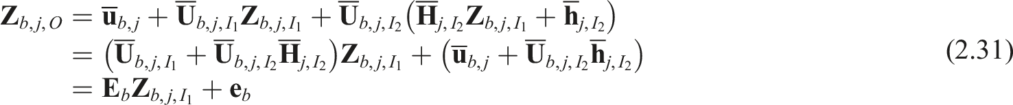
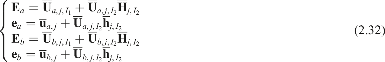
By using equation (2.31) to calculate

Equations (2.33) is the reduced transformation form of the output state vector of element j, and equation (2.34) is the recursive expression of
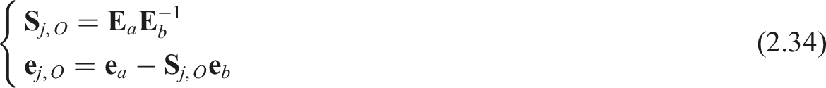
In the topology structure of a linear tree multibody system, the multibody system transfer matrix method divides the system into several single-input single-output elements and multi-input single-output elements. The derivation and calculation of the reduced transfer matrices for linear tree multibody systems can be achieved by combining the recursive relationship between single-input single-output elements and multi-input single-output elements. For the state vectors of each input of the system, after dividing them into blocks, according to the boundary conditions of the system, the state vector at the boundary is
After obtaining the
The reduced transformation form of the system output is

According to the boundary conditions of the system output,

By solving equation (2.36) as a non-homogeneous linear equation containing m/2 unknowns, the unknown elements in the output state vector of the system can be obtained.
After obtaining the state vector of the system output, the state vector of each connection point can be obtained by using equations (2.28) and (2.31), as shown in Figure 5. Derivation process of the GE-ABHs-DVAs metastructure using reduced multibody system transfer matrix method.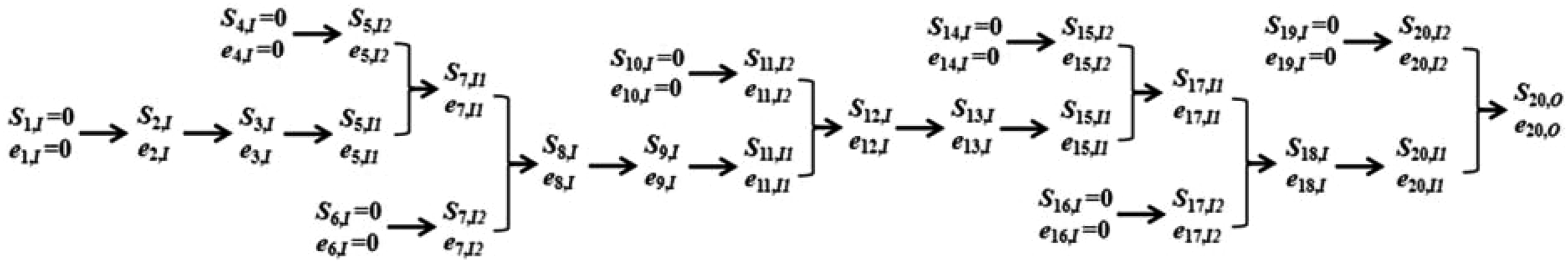
Derivation of steady state response
According to Figure 1(a), the metastructure has a sine excitation with a magnitude of F0 at a distance of xs from the left end in the y direction. That is, the load array is
The free boundary conditions at both ends of the GE-ABHs-DVAs metastructure indicate
According to the principle of vector partitioning, the

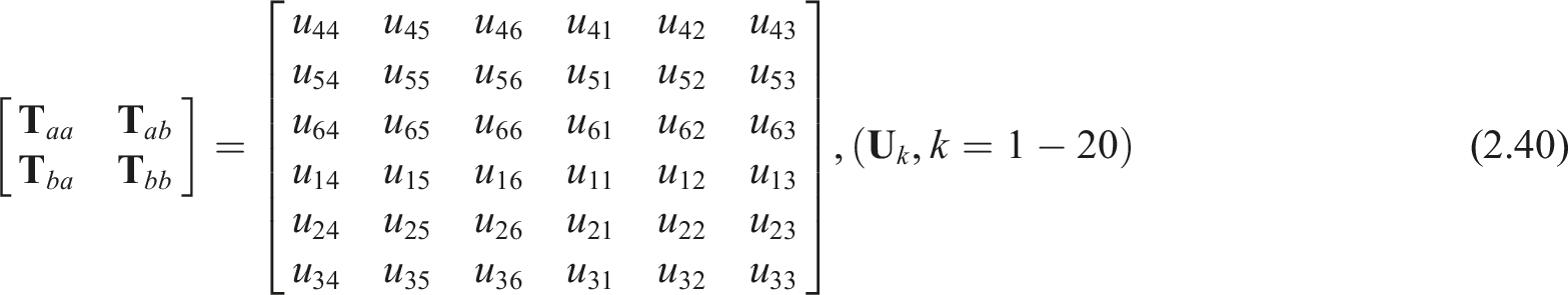
Since the state vectors are reordered, the transfer matrix and load array of each element also need to be rearranged. The rearranged matrices are as follows


According to the re-division of vectors, it can also be obtained that at the input boundary of the system, there are
In order to demonstrate the transmission relationship between input and output displacements, displacement transmission T is used9,11

Results and discussion
Model verification
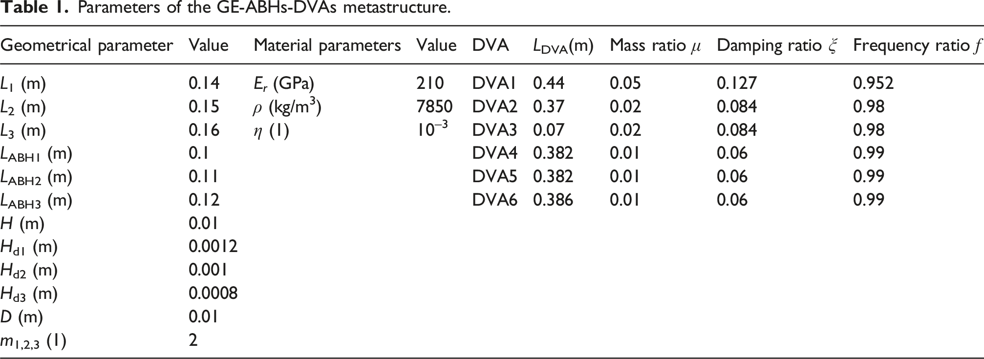
Parameters of the GE-ABHs-DVAs metastructure.
Parameters of the excitation.
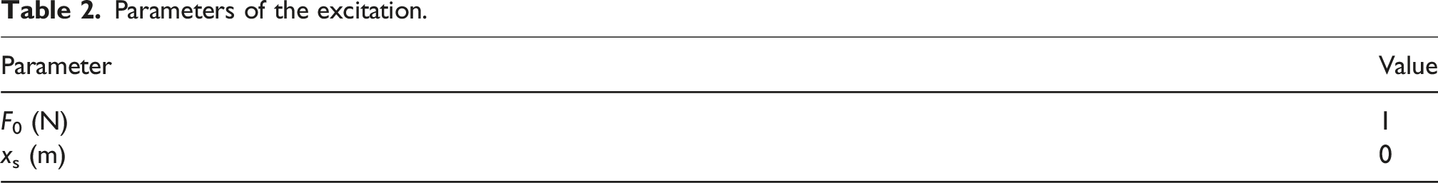
Figure 6 shows the displacement transmissions of the GE-ABHs-DVAs calculated by the FEM and RMSTMM. From Figure 6, it can be seen that the transmission curves obtained by the two methods agree very well, which verifies the correctness and accuracy of RMSTMM. With regarding to the computation time, the FEM takes 24 s while the RMSTMM takes 17.3209 s which is less than that by FEM. These suggest that for the proposed GE-ABHs-DVAs metastructure, the applied RMSTMM has higher calculation speed and efficiency than the COMSOL FEM. Comparison of displacement transmissions of the GE-ABHs-DVAs using RMSTMM and FEM.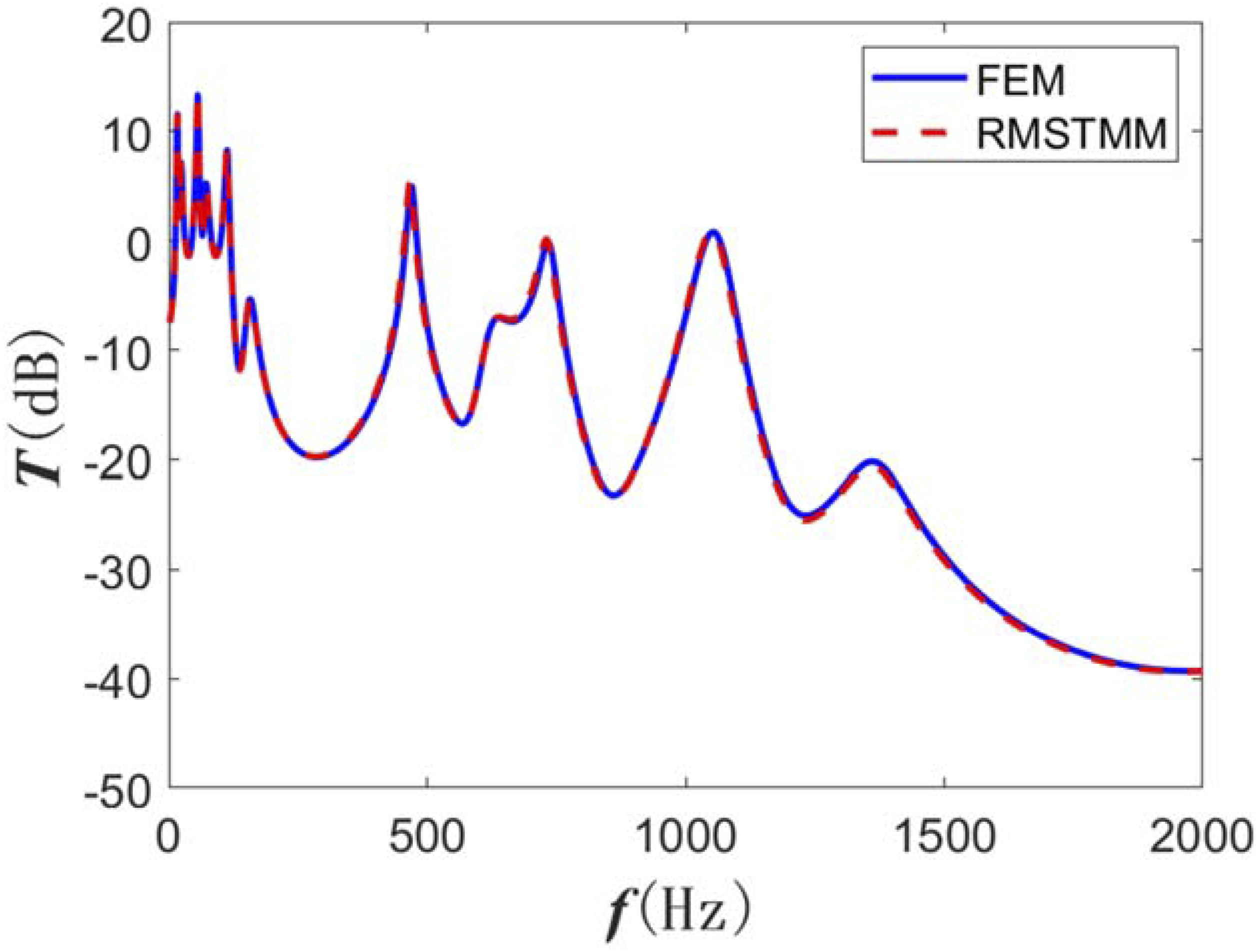
Optimized designs of ABHs and DVAs
To search for the optimal isolation performance of the GE-ABHs-DVAs metastructure, optimized designs of the metastructure were conducted in two steps. Firstly, the multi-population genetic algorithm is applied to optimize the gradient parameters of the GE-ABHs, including the length and truncation thickness gradients of the ABH beam element and the length gradient of the uniform beam element. It is note that the total length, width, and thickness of the GE-ABHs remain unchanged during the optimization. Then, the DVA parameters are optimized to minimize different formants of the GE-ABHs structure according to the peak frequency values and the vibration concentration positions of the optimized GE-ABHs based on the fixed-points theory.
Optimized design of GE-ABHs’ gradient parameters
In order to optimize the isolation performance of metastructures, it is necessary to first quantitatively define the isolation performance of the system, so as to facilitate subsequent research and establish optimization functions. In this section, a proportional coefficient R is proposed as the wideband performance evaluation index for the GE-ABHs structure isolation. R is defined as the proportion of the frequency range in which the displacement transmission T is less than the target value T
a

Here the target value T
a
is set to −6 dB, which means that the displacement is reduced by about 50% during the transmission process.
Before using multi-population genetic algorithm for structural optimization, it is necessary to set the fitness function. Here the fitness function is defined as
Equations (3.2) represents the degree of superiority of the vibration isolation performance of the GE-ABHs structure built from individual parameters in the population compared to the vibration isolation performance of the periodic embedded ABH counterpart.
The optimization ranges of parameters are constrained by the structure’ overall dimensions and manufacturing conditions—specifically, a machining accuracy of 0.1 mm, the requirement for moderate gradient variations in structural dimensions to ensure smooth impedance transitions, and the limitation that the thickness gradient of each ABH beam section must not exceed half the dimension of the reference section (ABH beam section 2), that is,
In Figure 7, the optimization process of the multi-population genetic algorithm for the GE-ABHs structure is shown. The termination parameter was set such that the optimal individual was retained in the essence population for 8 generations before the search was considered to be convergent. Evolution process of multi population genetic algorithm with three gradient lengths.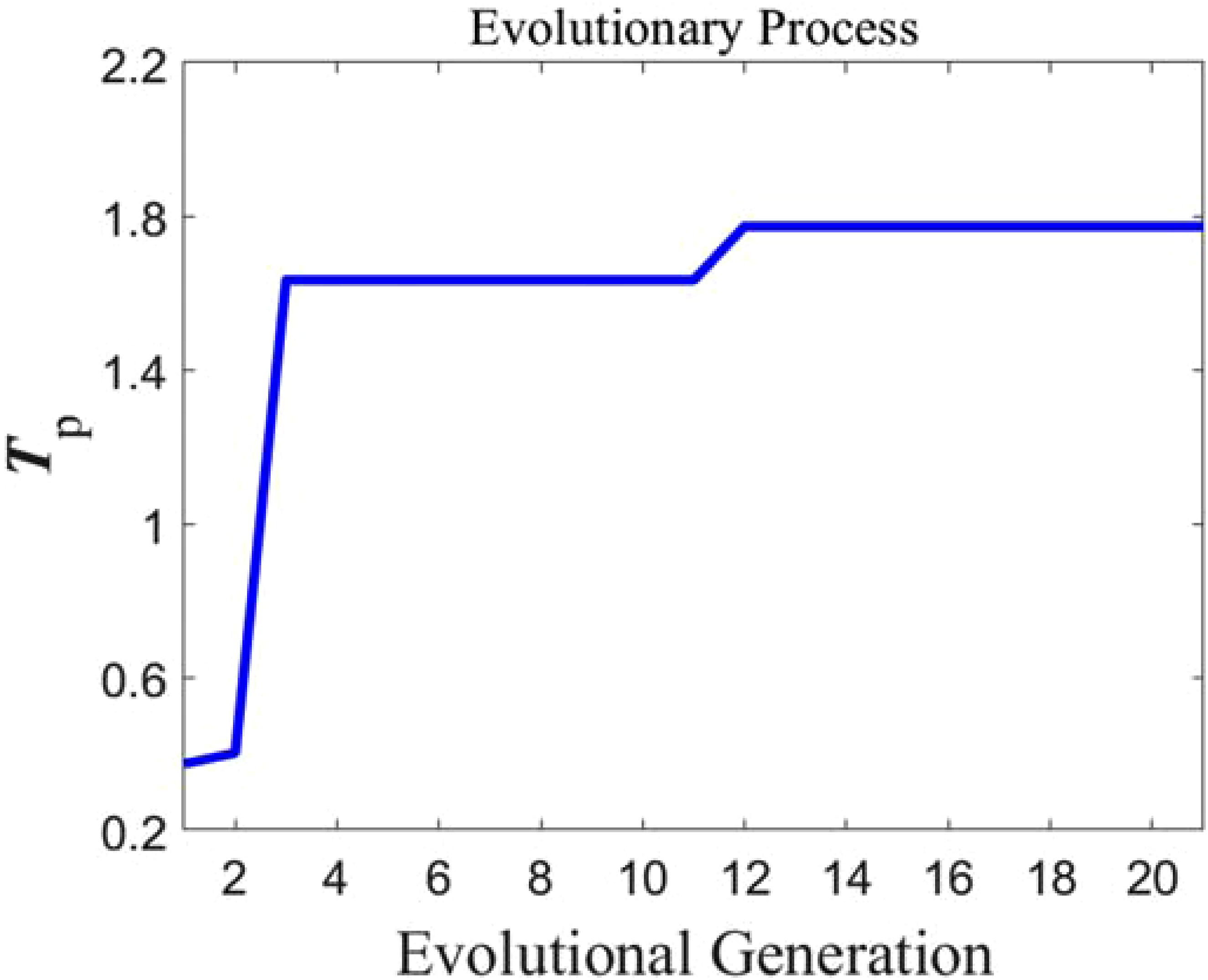
The optimized control parameters are as follows. The optimized gradient of LABH is 28.6 mm, the optimized gradient of Hd is −0.16 mm, and the optimized gradient of Luniform is −1.12 mm. The average displacement transmission of the optimized GE-ABHs structure is
Figure 8 presents the convergence analysis of the formant value of GE-ABHs before and after structural optimization. It can be observed that when the value of N reaches or exceeds 6 00, the variation of each formant value remains below 0.5%. Therefore, it can be concluded that the formant values achieve convergence at N = 600, and this value will be adopted for subsequent calculations in the following research. Convergence analysis of the formant value of the GE-ABHs. (a) Unoptimized (b) optimized.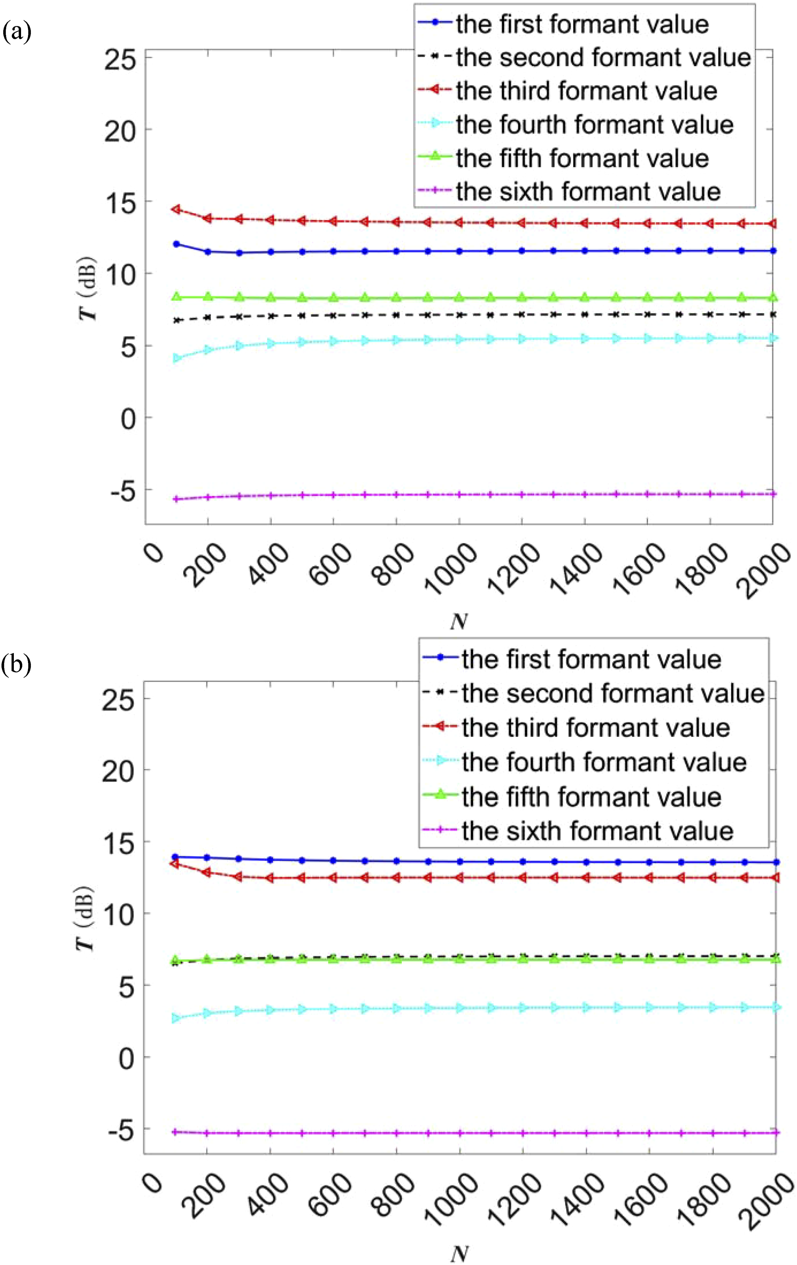
Figure 9 shows the comparison of displacement transmissions of GE-ABHs before and after the structural optimization. The un-optimized GE-ABHs structure has R = 0.719 and Comparison of displacement transmissions of the GE-ABHs before and after optimization.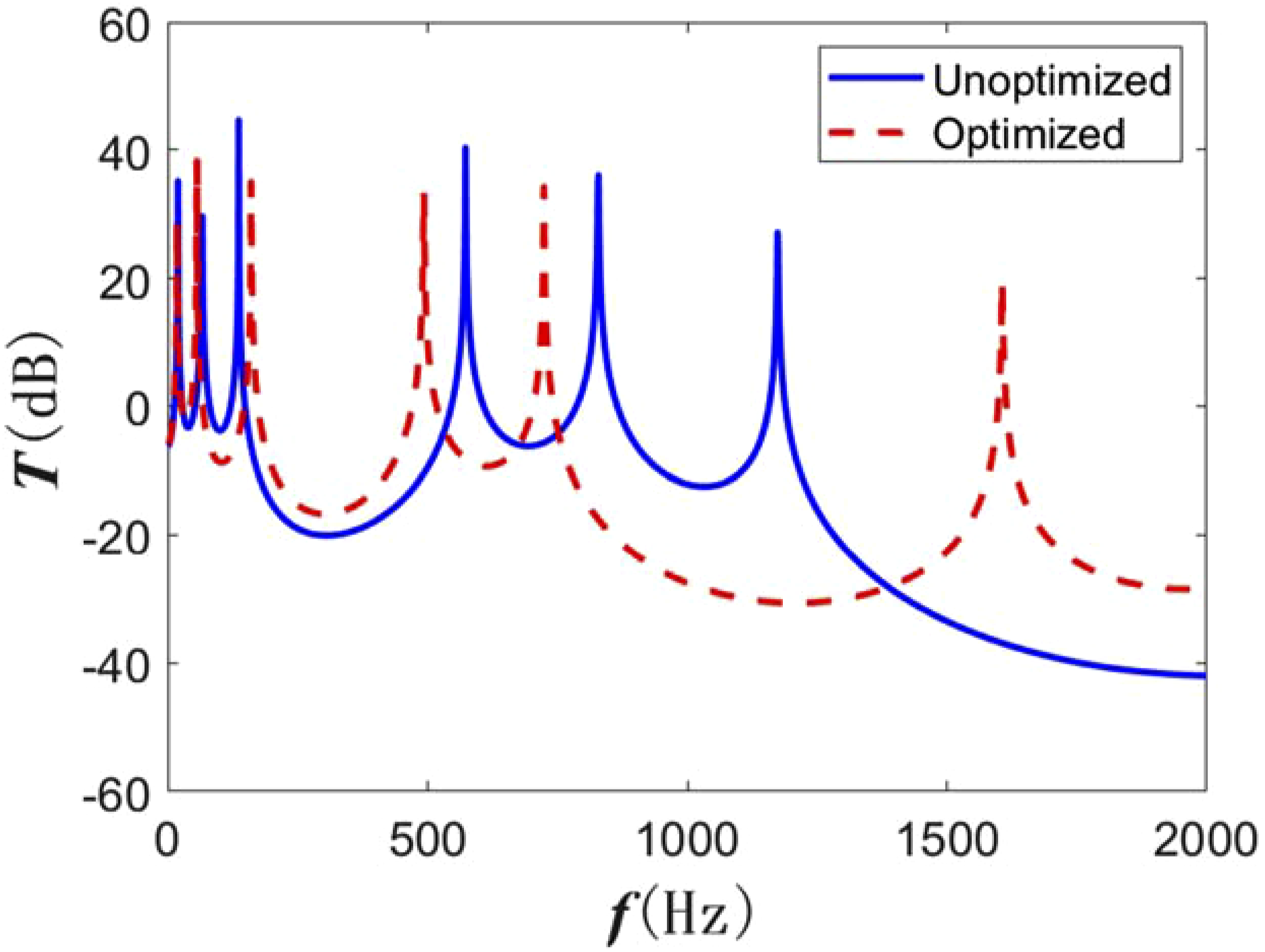
Optimized design of DVAs parameters
In order to find the best position to place the DVA device, so as to maximize the energy absorption effect of the DVA structure, it is necessary to find the energy accumulation position of the GE-ABHs structure. Figure 10 shows the spatial distributions of the displacement response of the GE-ABHs structure at each formant frequency of the displacement transmission in the frequency range of 1–2000 Hz. Spatial distributions of the displacement transmission response of the GE-ABHs. (a) At the first formant frequency, (b) at the second formant frequency, (c) at the third formant frequency, (d) at the fourth formant frequency, (e) at the fifth formant frequency, and (f) at the sixth formant frequency.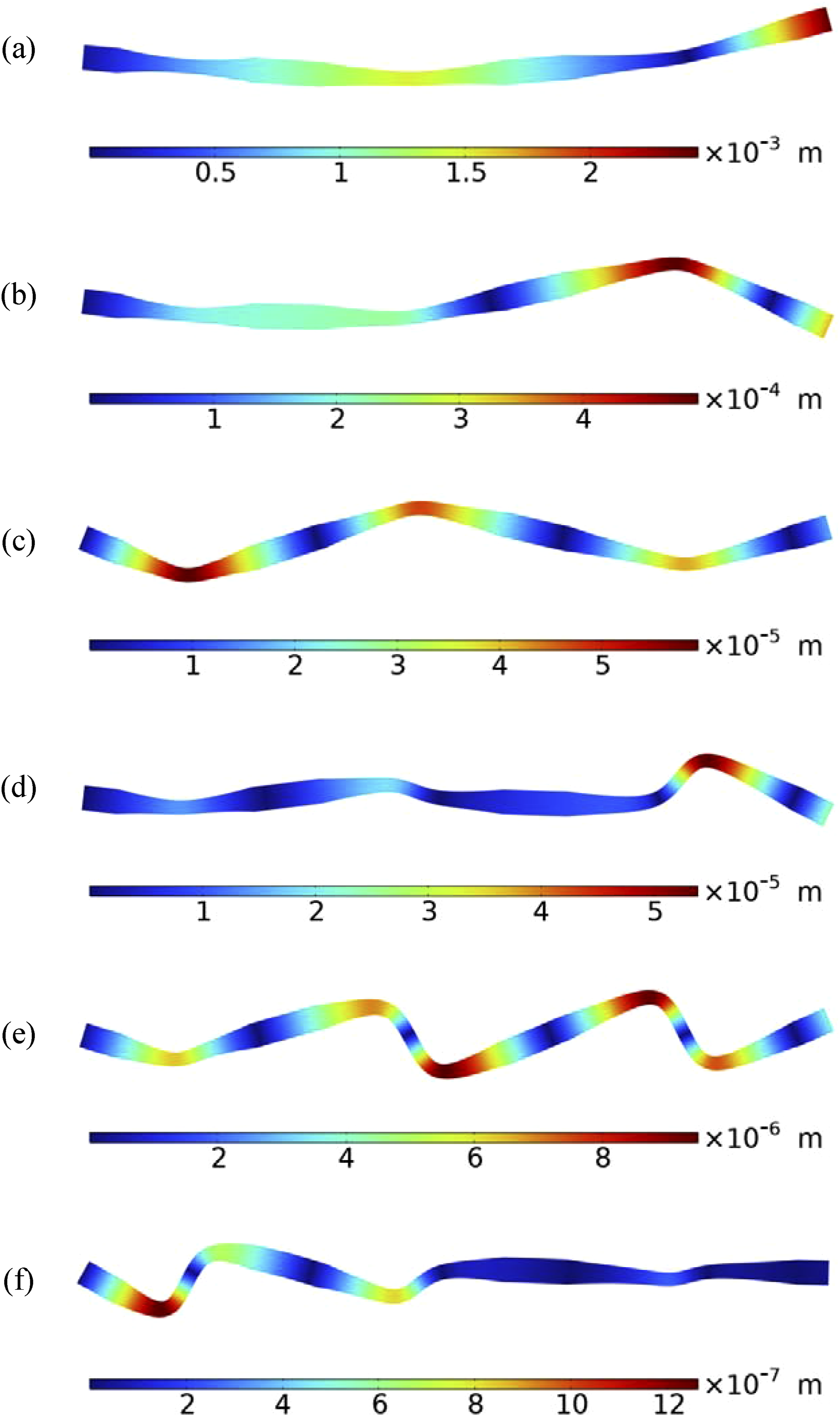
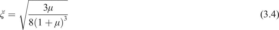
From Figure 10, the position of the maximum displacement amplitude of the GE-ABHs structure at each formant frequency can be located. Selecting the appropriate mass ratio μ of each DVA structure for each formant frequency, the frequency ratio ƒ of each DVA structure and the damping ratio ξ satisfying the optimal absorbing effect can be calculated based on the fixed-points theory1,25
DVA parameters for each formant.
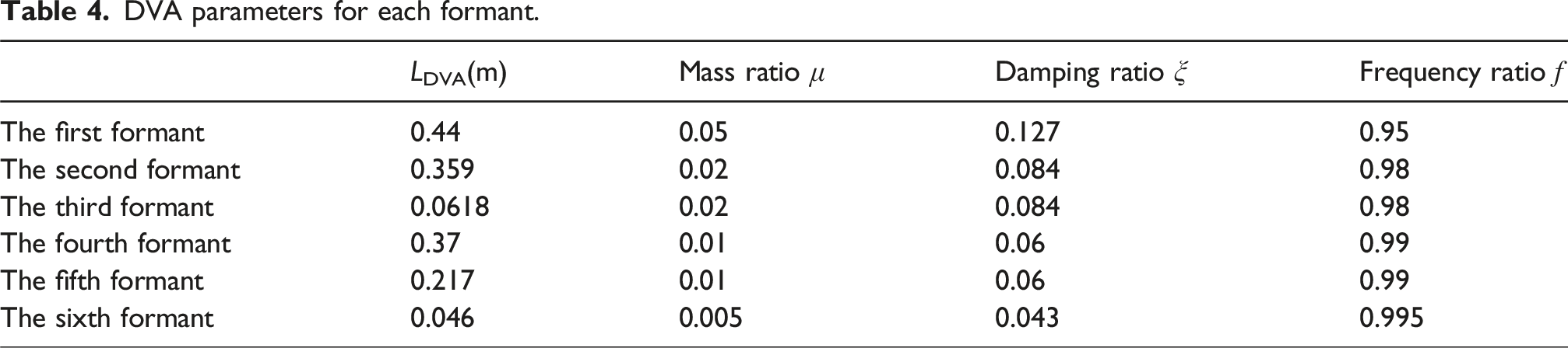
Figure 11 shows the comparison of the displacement transmissions of the optimized GE-ABHs-DVAs metastructure calculated by the FEM and RMSTMM, respectively. It can be seen from Figure 11 that the transmission curves calculated by the two methods are in good agreement, which verifies the correctness and accuracy of the RMSTMM. With regarding to the computation time, the FEM takes 18 s while the RMSTMM takes 16.6146 s. This suggests that for the GE-ABHs-DVAs metastructure, the RMSTMM exhibits higher calculation speed and efficiency than the FEM. Displacement transmissions of the optimized GE-ABHs-DVAs calculated by the RMSTMM and the FEM, respectively.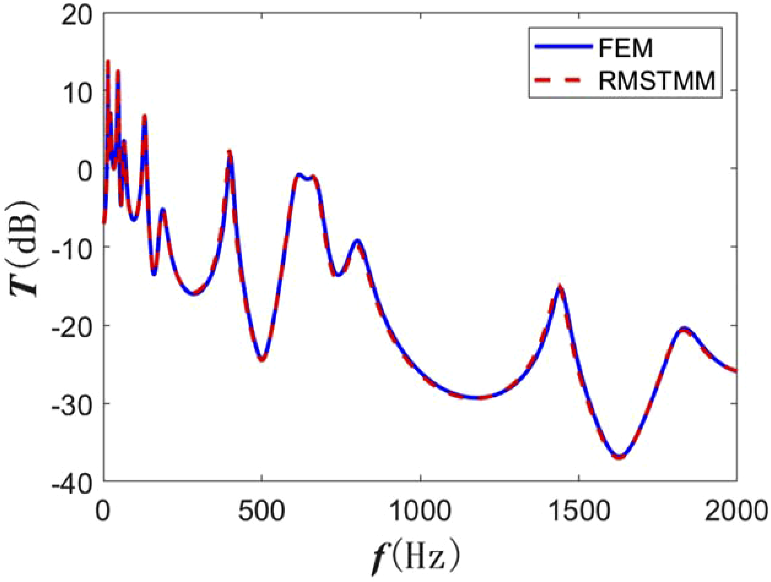
Performance and mechanism of the vibration isolation
In this section, the displacement transmission responses of the optimized metastructure with and without the attached DVAs (existing model) are calculated and compared based on the validated RMSTMM Euler–Bernoulli beam model.
As can be seen from Figure 12, when the DVAs designed for multiple formants are attached, all fix formants are split into two formants with lower peaks. This suggests that frequency matching occurs at all frequencies, validating the optimal design based on the fixed-points theory. Compared with the existing model without DVAs, the formant values of the metastructure with the DVAs are reduced by a minimum of 15.2 dB and a maximum of 47.5 dB, respectively, with an average reduction of 31.8 dB. This demonstrates the excellent low-frequency broadband vibration isolation effect of the proposed GE-ABHs-DVAs compared with the existing model. Displacement transmissions of the optimized GE-ABHs-DVAs without and with attached DVAs.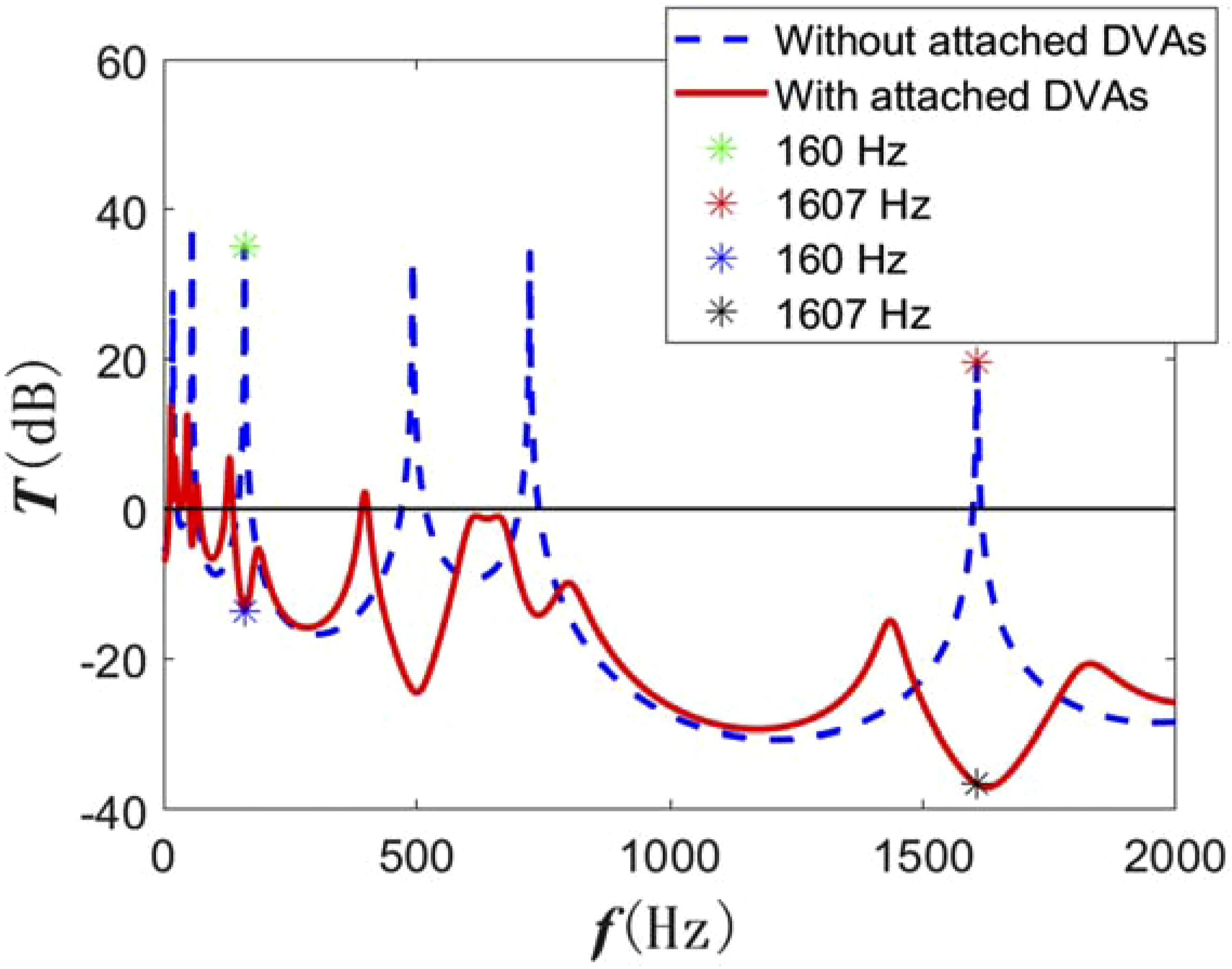
In order to disclose the underlying vibration isolation mechanism, the spatial distributions of the displacement responses of the GE-ABHs-DVAs at two typical frequencies with and without the DVAs (marked in Figure 12) are investigated and shown in Figure 13. These two frequencies correspond to the third and sixth resonance frequencies of the GE-ABHs-DVAs without the attached DVAs (or GE-ABHs) and to the attenuation dips of the GE-ABHs-DVAs. In Figure 13, the x-axis represents the position of the GE-ABHs-DVAs metastructure along the x-direction, the gray area represents the ABH section area, and the y-axis represents the y-directional displacement responses (Y) normalized with respect to the y-directional displacement response at the input point (Yinput), that is, Spatial distribution of the displacement response for the GE-ABHs-DVAs.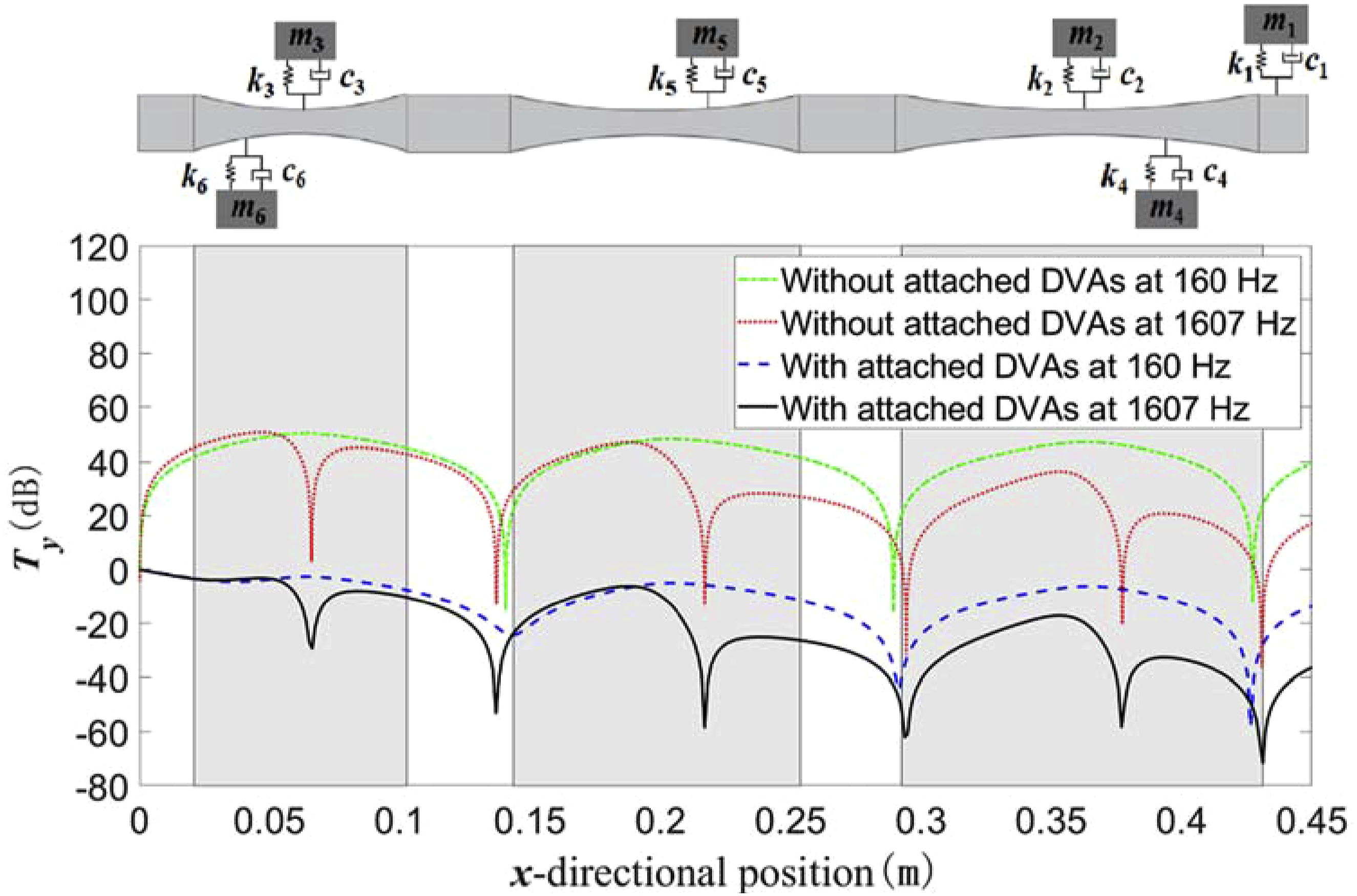
As shown in Figure 13, for the GE-ABHs-DVAs without the attached DVAs, the vibration displacement at both frequencies is much amplified with respect to that at the input, especially near the ABH wedge (where the DVAs are to be installed). This explains the high displacement transmissions at the two frequencies. With the DVAs attached to the points of vibration concentration, the vibration along the entire structure at both frequencies is significantly reduced compared to the vibration at the input. In particular, near the DVAs, the displacement is extraordinarily suppressed. This indicates that the damped DVAs device acts as an energy absorber, so that the energy accumulated by the GE-ABHs is effectively suppressed by the DVAs and thus the transmitted vibration displacement at various positions are greatly attenuated. This demonstrates that the GE-ABHs-DVAs metastructure combines the advantages of the ABHs structure and the DVAs device and achieves low-frequency broadband vibration isolation.
Experimental test
In this section, the low-frequency broadband vibration isolation effect of the optimized GE-ABHs-DVAs metastructure is verified by experiments. 45 steel was used to fabricate the GE-ABHs structure samples and uniform beam counterpart by WEDM, and six metal blocks with different masses were also prepared from 45 steel to simulate the mass blocks of the DVAs. Asphalt mastic was used to simulate the spring and damping system in the DVA, which was also used to stick the metal blocks to the GE-ABHs structure.
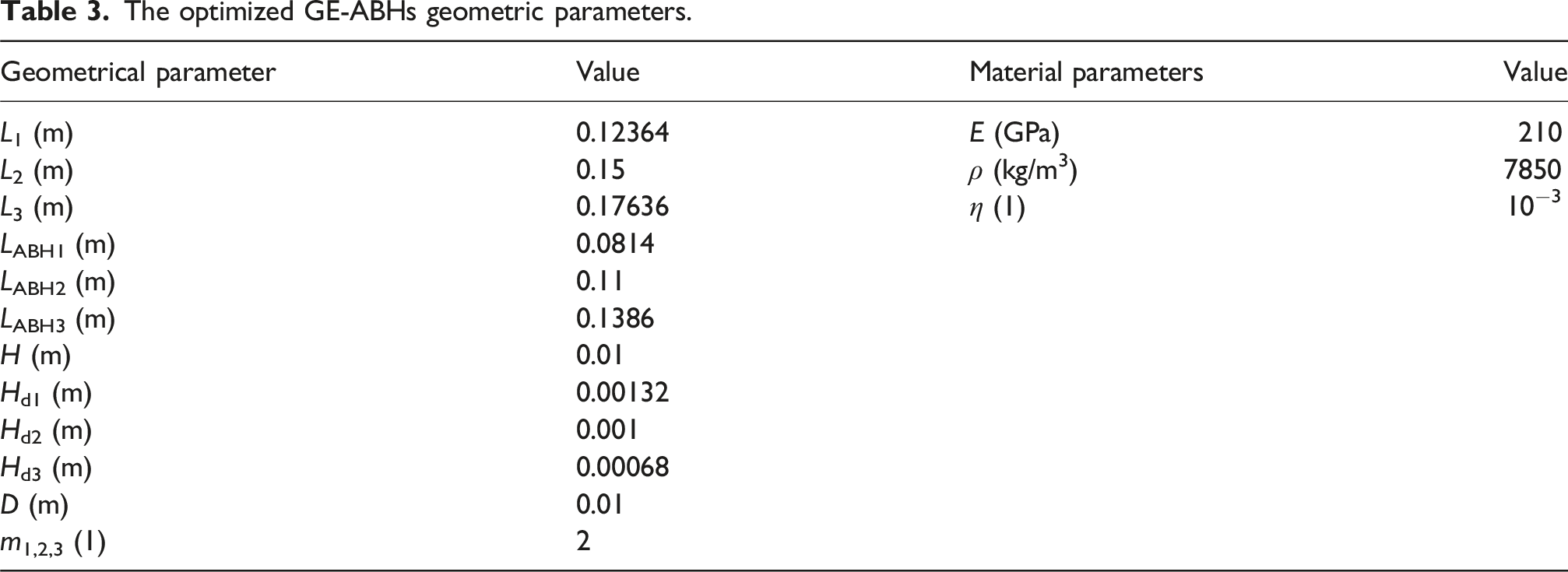
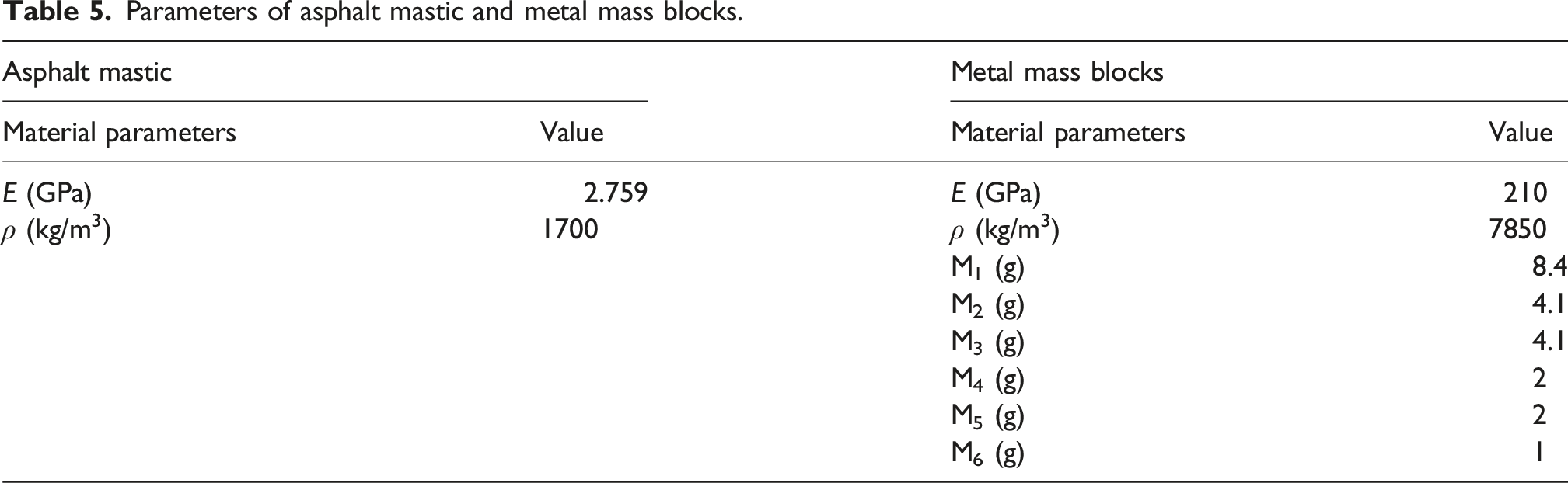
The samples of the prepared uniform beam and the GE-ABHs-DVAs metastructure are shown in Figure 14. Here the dimensions of the uniform beam are 450 × 10 × 10 mm, and the dimensions of the GE-ABHs-DVAs metastructure are referred to the optimized material parameters in Table 3. Note that the geometric dimensions of the uniform beam and the total length of the GE-ABHs structure have an error of less than 0.5%, and the processing error of the uniform beam thickness and truncation thickness of the GE-ABH structure is within 1%. The material parameters of the asphalt mastic and metal blocks are given in Table 5. Test samples. (a) The uniform beam sample (b) the optimized GE-ABHs-DVAs metastructure sample. Parameters of asphalt mastic and metal mass blocks.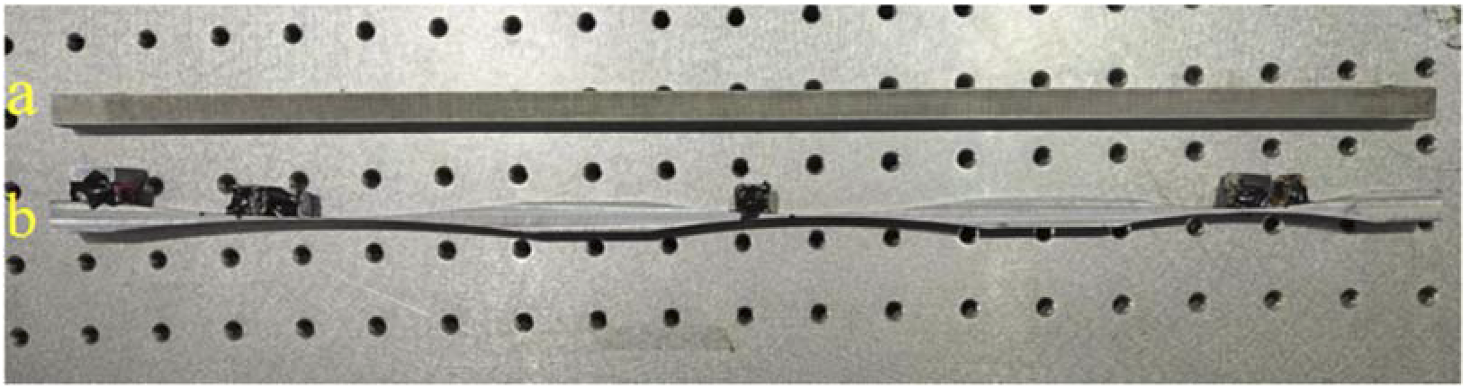
In this experiment, a thin nylon rope was used to suspend the test specimen on a bracket fixed to the isolation platform, in order to simulate the free-free boundary conditions of the samples. The signal generator (DG 1022Z) generated a sine sweep signal with a frequency range of 1–2000 Hz. The sweep signal was amplified by a power amplifier (YE5871A) and transmitted to the exciter (JZK-5) fixed to the isolation platform. The exciter was connected to the test specimen through a magnetic suction head and excited with a sine sweep signal. The dynamic signals were captured by the impedance head (CL-YD-331) or a combined force and acceleration sensor end, and a laser vibrometer (Polytech OFV-505), which were then fed into aa PC data analysis system. The test set-sup is shown in Figure 15. Experimental set-up.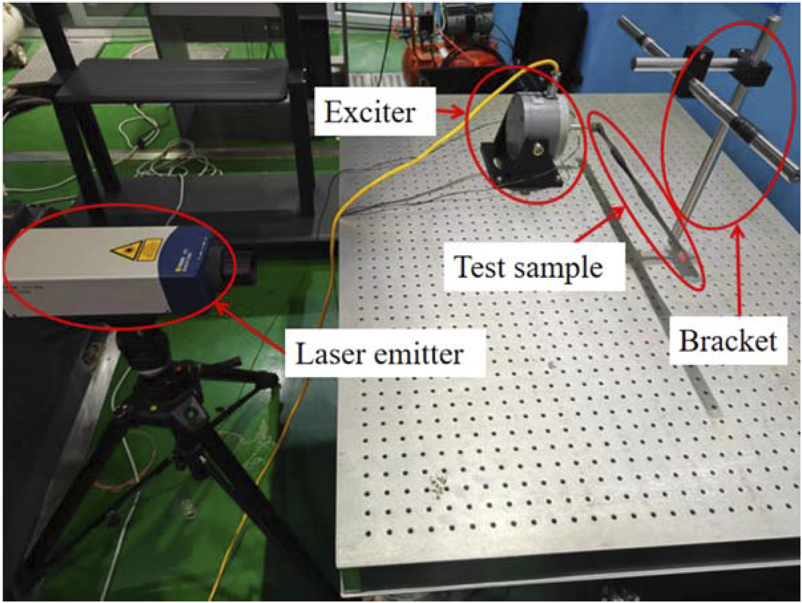
Figure 16 shows the comparison of the experimental and theoretical results of the displacement transmission of a uniform beam sample. As can be seen from this figure, the uniform beam theory is in good agreement with the experimental curve, and the resonance peak position and amplitude are generally consistent. Comparison of experimental and theoretical transmissions of an uniform beam.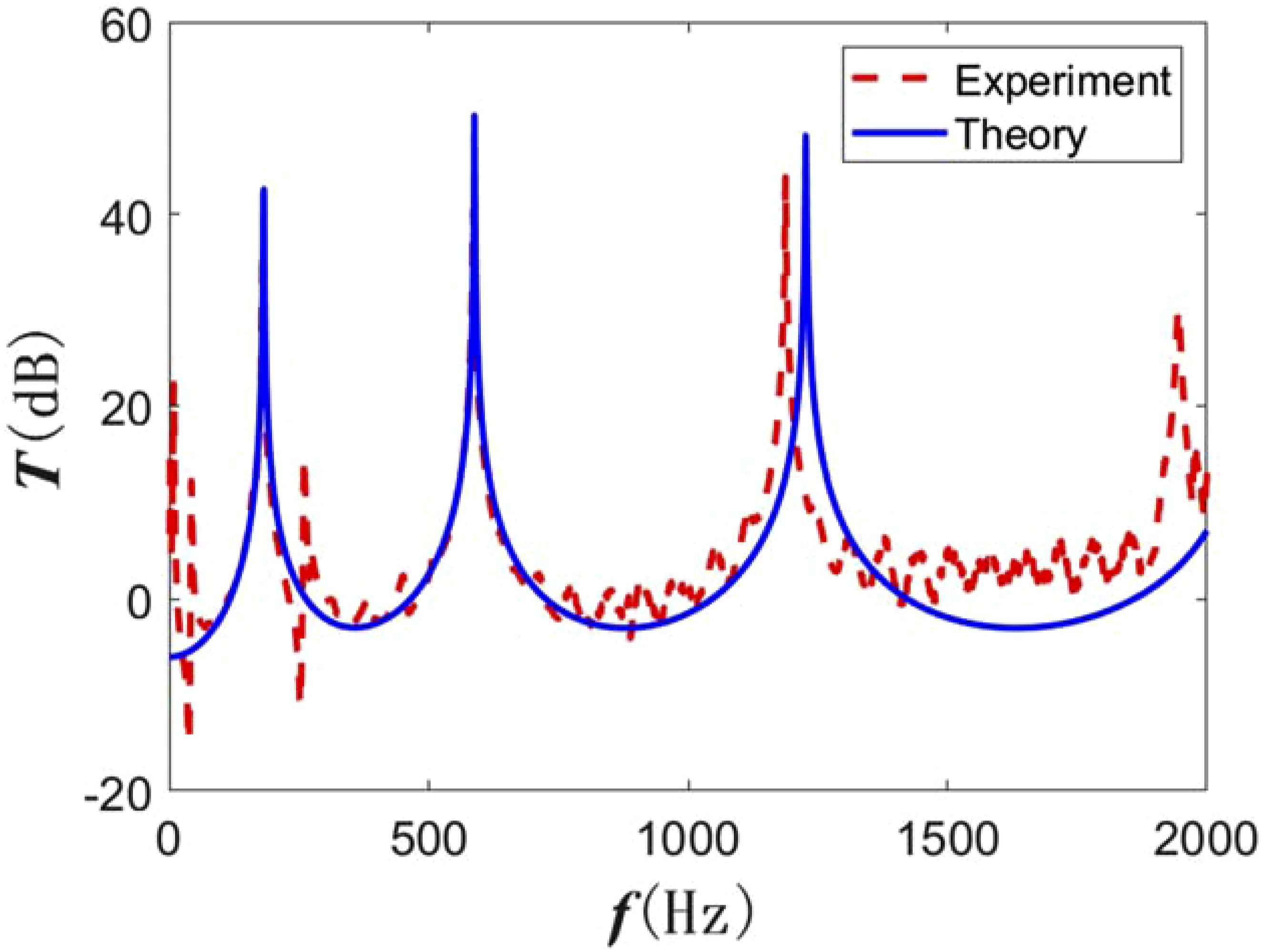
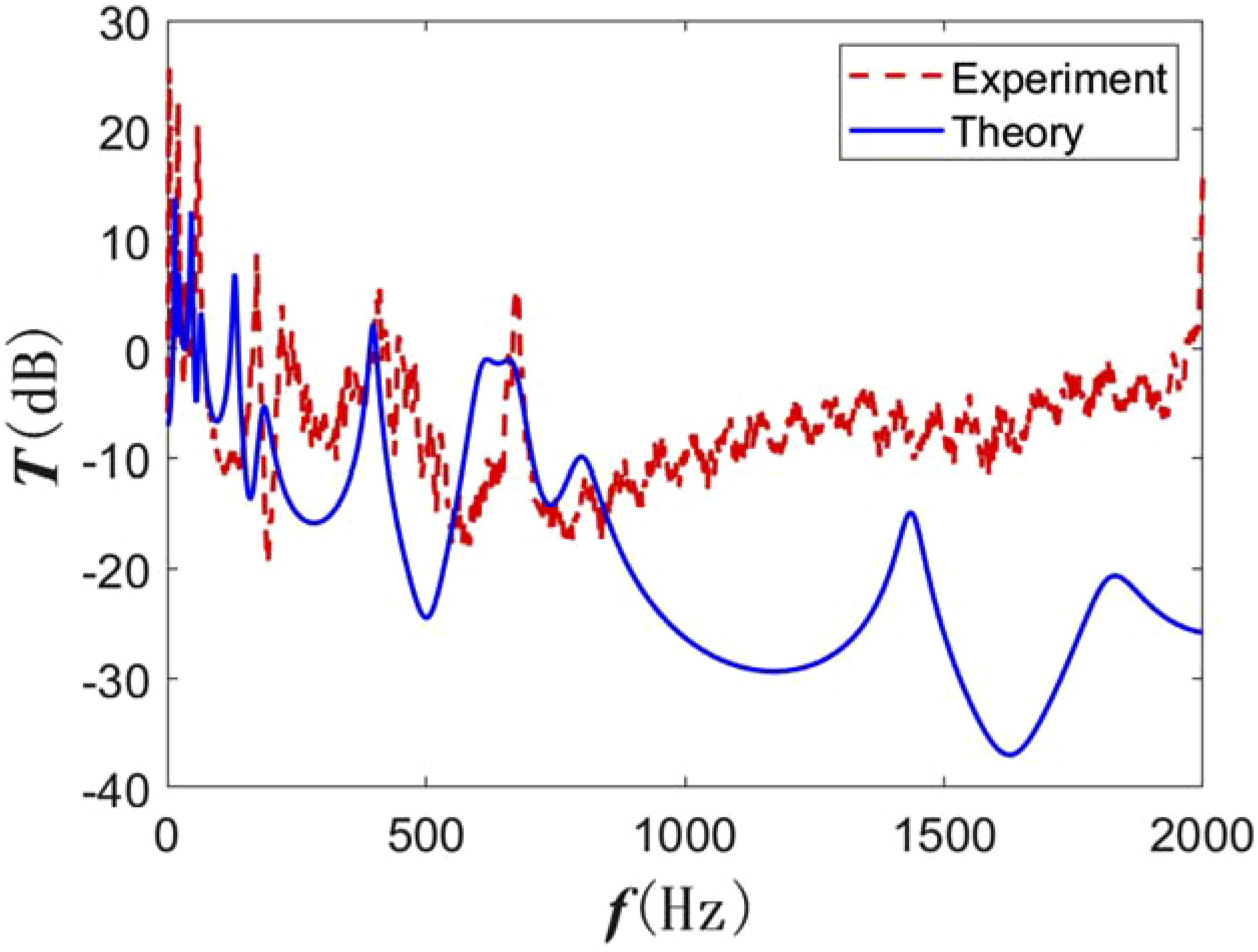
Figures 17 and 18 show the comparison between experimental and theoretical results of displacement transmissions for the GE-ABHs structure and the GE-ABHs-DVAs metastructure, respectively. From the figures, it can be seen that the experimental results agree with the theoretical solution in the low and medium frequency range. Some discrepancies occur in the high frequency range, which can be attributed to the Euler–Bernoulli beam model used in the RMSTMM, which neglects the effects of shear deformation and rotational inertia. Additionally, the method of simulating DVAs using asphalt-attached metal blocks in the experiments, as well as dimensional errors in the fabrication of the test specimens, could also contribute to deviations in the experimental results. It is also observed from comparisons of Figures 17 and 18 that the vibration transmission with the attached DVAs show broadband low-frequency attenuations, verifying the low-frequency broadband isolation performance of the GE-ABHs-DVAs metastructure. Comparison of experimental and theoretical transmissions of the GE-ABHs sample. Comparison of experimental and theoretical transmissions of the GE-ABHs-DVAs metastructure sample.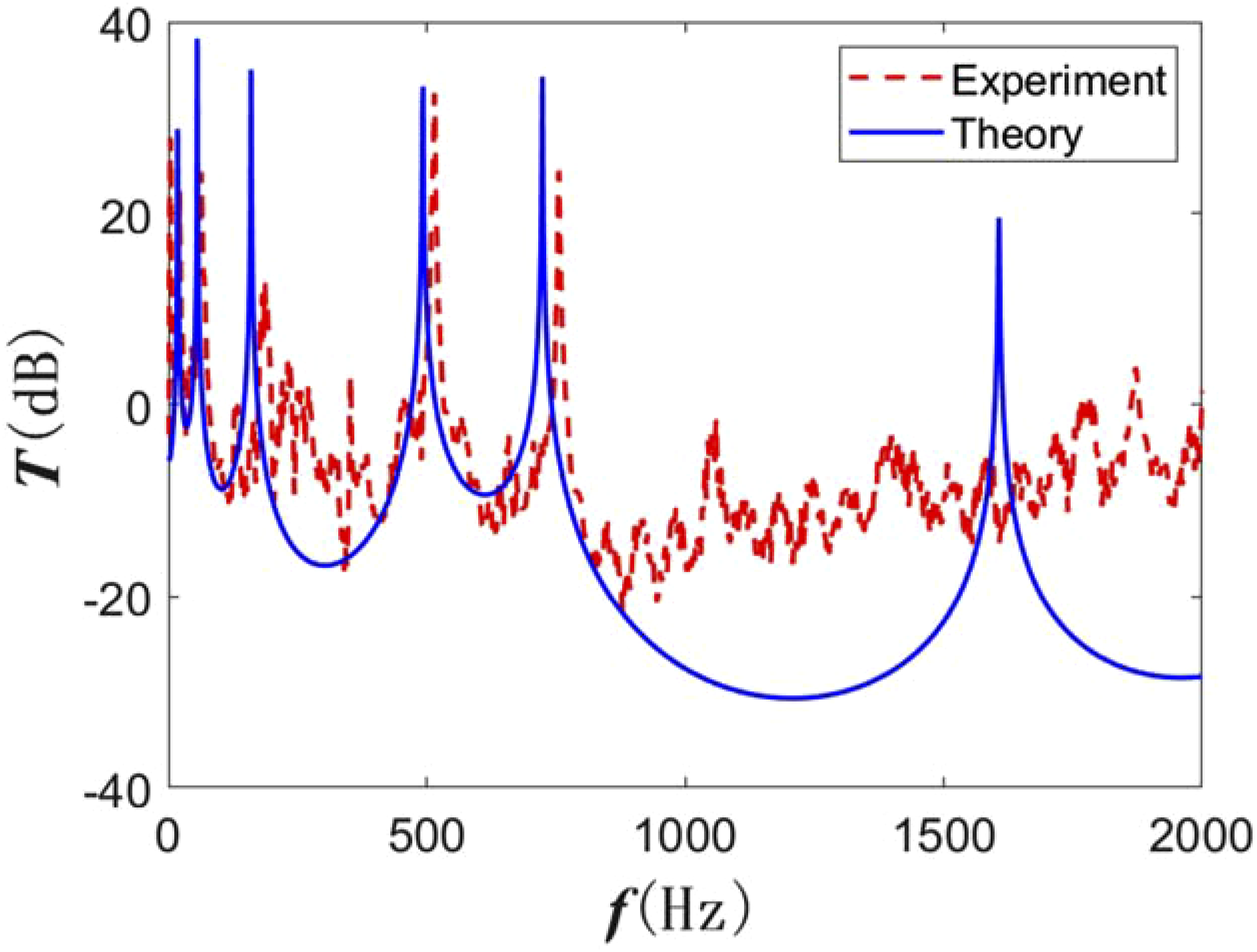
Conclusions
This article is dedicated to the effective computation methods for the design of a GE-ABHs structure with additional DVAs or GE-ABHs-DVAs metastructure with improved broadband low-frequency vibration isolation performance.
Firstly, a dynamic model of the GE-ABHs-DVAs metastructure was established based on the RMSTMM, and the transfer matrices and the steady-state response of the metastructure were derived. The high accuracy and computational efficiency of RMSTMM were verified through comparing with FEM results. Optimized designs of the metastructure were then conducted in two steps. Firstly, the multi-population genetic algorithm is used to optimize the gradient parameters of the GE-ABHs, and the gradient parameters with optimal isolation performance were found. Then, the DVA parameters are optimized to minimize different formants of the GE-ABHs structure according to the peak frequency values and the vibration concentration positions of the optimized GE-ABHs based on the fixed-points theory. Results show that the optimized metastructure could achieve a significant reduction of all formants below 2000 Hz, and a significant improvement in low-frequency broadband vibration isolation performance. The vibration mechanism was then analyzed based on the spatial distribution of vibration displacement response. Finally, samples of the optimized metastructure was manufactured and experimentally tested to verify its low-frequency broadband isolation effect and the correctness of the RMSTMM theoretical calculation results.
To sum up, the GE-ABHs-DVAs metastructure achieves the complementary advantages of ABHs and DVAs, effectively combining the energy concentration effect of ABH and the energy absorption effect of DVA, thus overcoming the limitations of traditional passive vibration isolators and achieving broadband low-frequency isolation effect. This paper thus provides both an efficient computation method for complex ABH isolation structures and a broadband low-frequency vibration isolation strategy.
Footnotes
Funding
The authors disclosed receipt of the following financial support for the research, authorship, and/or publication of this article: This work was supported by the Equipment Pre-Research Field Fund (Grant Nos. 80910010102), and Shuangchuang Program of Jiangsu Province (Grant No. JSSCBS20210240).
Declaration of conflicting interests
The authors declared no potential conflicts of interest with respect to the research, authorship, and/or publication of this article.