
Abstract
As an emerging technology, electrically assisted turbocharging (EAT) technology can effectively solve the problem of turbo lag of traditional turbochargers. The turbocharger (TC) rotor was discretized to establish a finite element model and its effectiveness was verified based on experiments, and then the EAT rotor design was carried out. The linear and nonlinear dynamic analysis of EAT rotor semi-floating floating ring bearing (SFRB) system is carried out. The results show that the critical speed of EAT rotor is lower than that of TC rotor. The larger internal clearance will cause strong sub-synchronous vibration of the EAT rotor in the low-speed stage. Properly reducing the internal clearance can effectively suppress the sub-synchronous vibration at low speed, and the high-speed rotor performs balanced motion on the “critical limit cycle.” Taking the EAT with low vibration noise and efficient operation as the goal, it is recommended to keep the inner clearance size at about 0.315 mm.
Keywords
Introduction
With the rapid development of the global transportation industry, the consumption of energy, especially non-renewable energy, has increased, and it has also brought about problems such as high carbon emissions and environmental pollution. 1 The new emission regulations put forward higher requirements for the performance of the internal combustion engine. At present, the widely used exhaust gas turbocharger (TC) effectively increases the intake air volume of the internal combustion engine, which makes the internal combustion engine have stronger power.2,3 However, due to the large rotational inertia of the exhaust gas TC rotor and the elastic buffering effect of the air in the intake manifold, the engine intake supply is not synchronized with the fuel supply, which makes the fuel combustion incomplete, resulting in high emission of the engine, insufficient power, and poor transient response. 4
At present, there are many improved technologies of exhaust gas turbocharging system, such as sequential turbocharging technology,5,6 two-stage turbocharging technology,7,8 variable geometry turbocharging technology,9,10 and so on. With the application of these technical means, the engine is developing toward higher power density, lower emissions, and lower fuel consumption. However, with the increase of boost pressure, the problem of insufficient torque at low speed is prominent, and the transient response of the engine still needs to be further improved. Hu 11 proposed that the electric turbocompound system used for heavy diesel engines has significant advantages in improving fuel efficiency, reducing emissions of carbon and nitrogen oxides. The EAT system is expected to effectively improve the transient response of TC, significantly increase the pressurization pressure, and improve the output power and efficiency, so as to solve the long-standing problem of “turbo lag.” In the future, in the face of new challenges and new trends in international energy supply and demand, EAT technology will be more widely developed and applied in vehicles and ships, but its rotor must be guaranteed to operate efficiently and stably.
In the current research, emphasis is placed on the improvement of engine performance through EAT. Although there are experimental operations, the vibration of the EAT rotor is ignored. Song 12 studied the trade-off relationships between various performance standards based on a model of a heavy diesel engine equipped with EAT. Proposing that reasonably managing these relationships is beneficial for improving turbocharging response and reducing emissions. Subramaniam 13 evaluated the potential for energy recovery and rapid turbocharging of EAT. Lee 14 conducted experiments on a turbocharged engine equipped with an electric compressor. It was found that a significant increase in average effective pressure and improved fuel economy. Shen 15 studied the impact of an electric turbocharger on the performance of an LP-EGR turbocharged engine through simulation. Results showed its huge advantage in improving engine performance at high speeds. Huang 16 conducted experimental studies on the performance and emissions of an electric turbocharged engine. The experimental results proved that the electric turbocharger enhanced the dynamic characteristics of the engine at low speeds.
Comparison of studies.
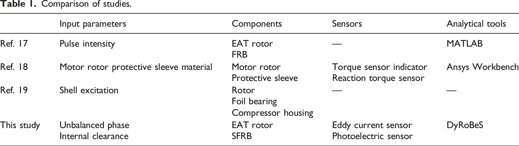
To date, there has been no report on the dynamic behavior of the EAT rotor in SFRB clearance variations. However, similar FRB-TC rotor system studies can provide strong support for the arguments put forward in this study. Zhang 20 proposed that the design of the three-lobed shape inside FRB can reduce synchronous vibration and suppress high amplitude sub-synchronous vibration. Ouyang 21 studied the effect of weight on the critical speed of a tilted TC rotor with FRB and found that increasing the tilt angle would lower the critical speed. Cao 22 analyzed the nonlinear dynamic characteristics of a TC supported by tilting pad bearings. It was observed that the rotor supported by tilting pad bearings exhibited stable periodic motion at low speeds, and quasi periodic motion at high speeds. Novotny 23 solved the dynamic problems in the TC rotor-bearing system. The results indicated that the importance of these mechanisms depends on the geometric dimensions and operating conditions of the system. Wang 24 studied the typical failure mechanisms and vibration characteristics of TC rotor systems and proposed an improved four node comprehensive parameter method to establish a dynamic simulation model of the rotor system. Liang 25 pointed out that there was a trade-off range in the design of SFRB clearance, which weakens the sub-synchronous vibration.
In this study, a finite element model of a marine TC rotor was established. The model was verified by the axis orbit test and the EAT rotor design was carried out. First, the linear analysis of EAT and TC rotors was carried out, and the critical speed, modal shape, and instability speed evaluation were compared. Subsequently, the dynamic behaviors of the nonlinear response models of the fault-free normal and the unbalanced rotors with the change of the internal clearance were discussed. Predicting synchronous/sub-synchronous vibrations and considering the shaft center trajectory at the corresponding rotational speed. This research provides a reference for the design of EAT rotor to reduce the cost of expensive experimental tests and shorten the development and design time.
Theory
A real TC rotor-SFRB system is shown in Figure 1. The rotor weight of the marine TC is 6.5 kg, and the rotor length is 308 mm. The rotor is a typical double cantilever rotor supported by two identical SFRBs. The compressor impeller and turbine are outside the support position of the SFRB, and the span of the two bearings is 64.81 mm. The working speed range of the marine TC journal is 30,000 r/min–60,000 r/min. In order to fully understand the vibration characteristics of the rotor under high-speed conditions, the rotational speed is studied from 10,000 r/min to 80,000 r/min. The first consideration of rotor dynamics design of high-speed rotating machinery is to control and reduce vibration. Large amplitude vibration will produce noise and may have a large amplitude, so that the rotor-stator friction occurs. In the design stage of the EAT rotor, it is necessary to fully consider the influence of various influencing factors on the EAT rotor. As a part of the system, the bearing has a significant impact on the system characteristics. In particular, the influence of internal clearance changes on the EAT rotor needs further study. SFRB-TC rotor structure diagram.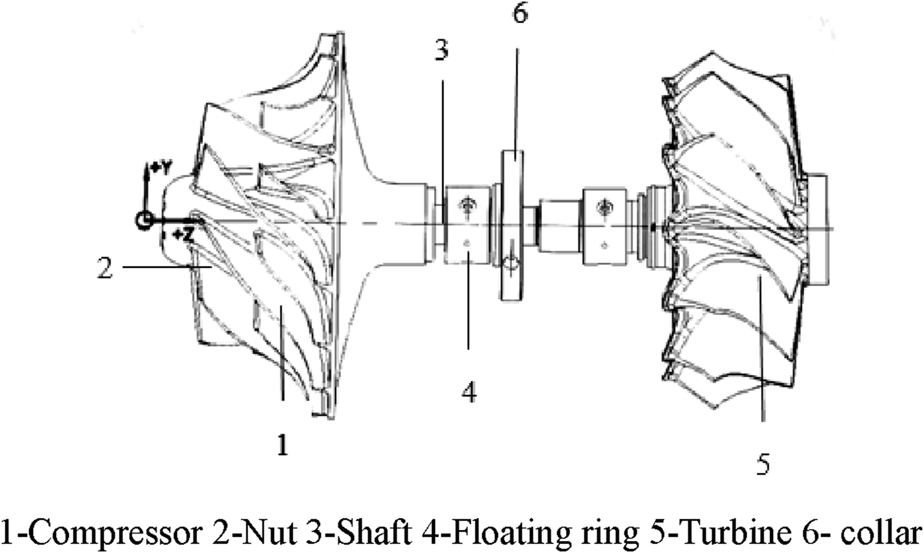
Mathematical model of SFRB
The profile of a SFRB is shown in Figure 2(a). The geometric structure and lubrication conditions of the SFRBs at the compressor end and the turbine end of the marine TC are the same. Because a ring is added between the shaft and the bearing seat, the ring divides the lubricating oil of the SFRB into two layers of oil film. The elastic pin limits the rotation of the floating ring. Therefore, the inner oil film has only one rotating surface, namely, the journal, and the outer oil film does not flow circumferentially. It can be regarded as a squeeze film damper (SFD). Without considering the external oil film, the oil film pressure profile in the turbine end bearing is shown in Figure 2(b). Profile of SFRB and oil film pressure profile. (a)Section of SFRB and (b) oil film pressure profile in 60,000 r/min.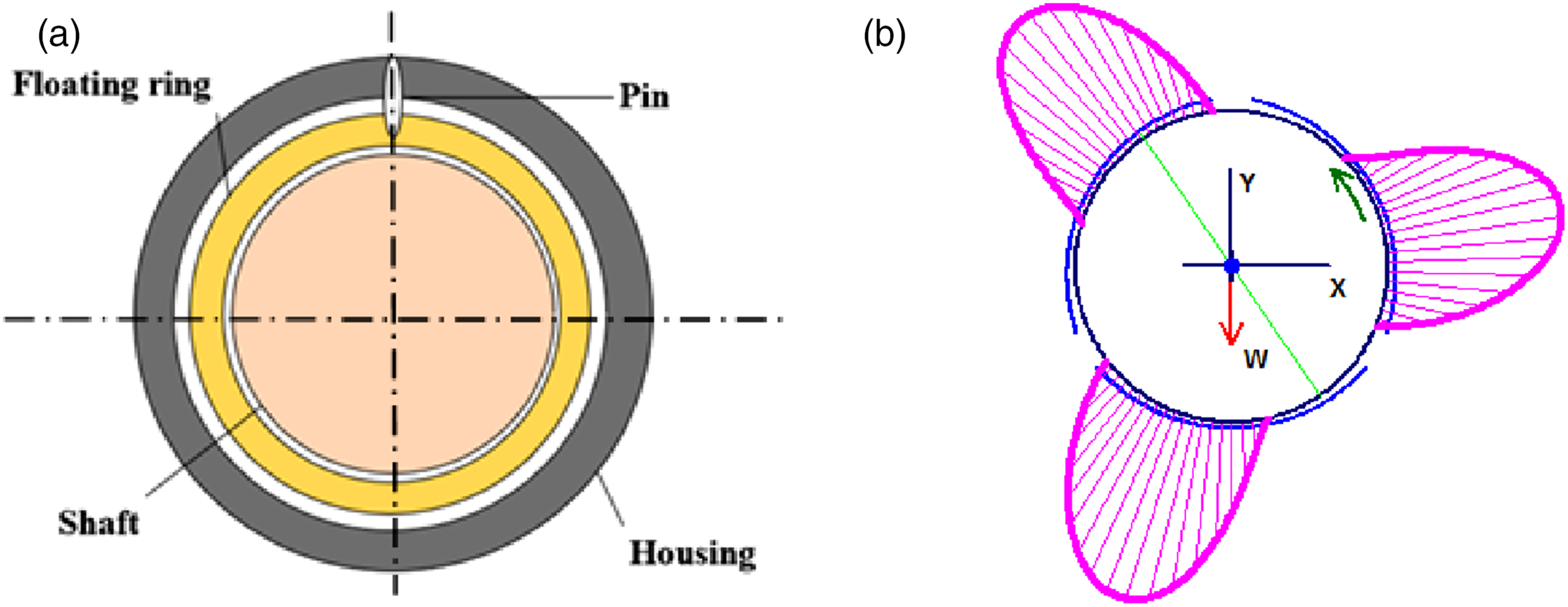


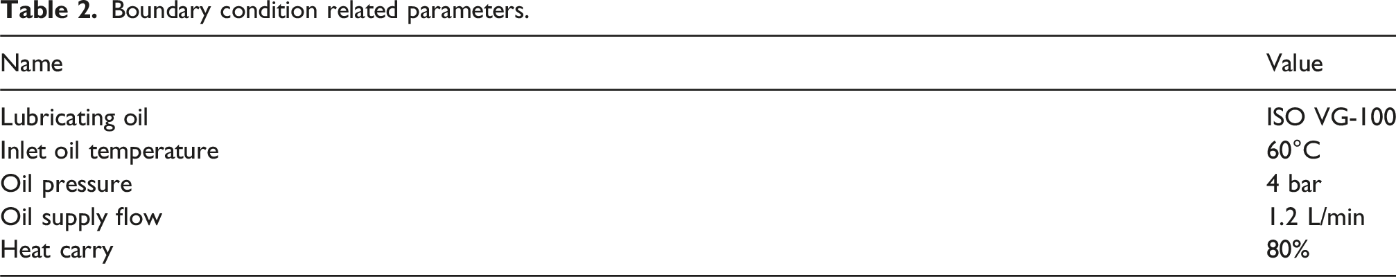
Boundary condition related parameters.
Isothermal analysis assumes that viscosity is constant throughout the membrane and reasonably assumes it as a function of temperature. Its viscosity-temperature curve as shown in Figure 3. The viscosity details of the lubricating oil have been embedded in the software. Viscosity-temperature curve of ISO VG-100.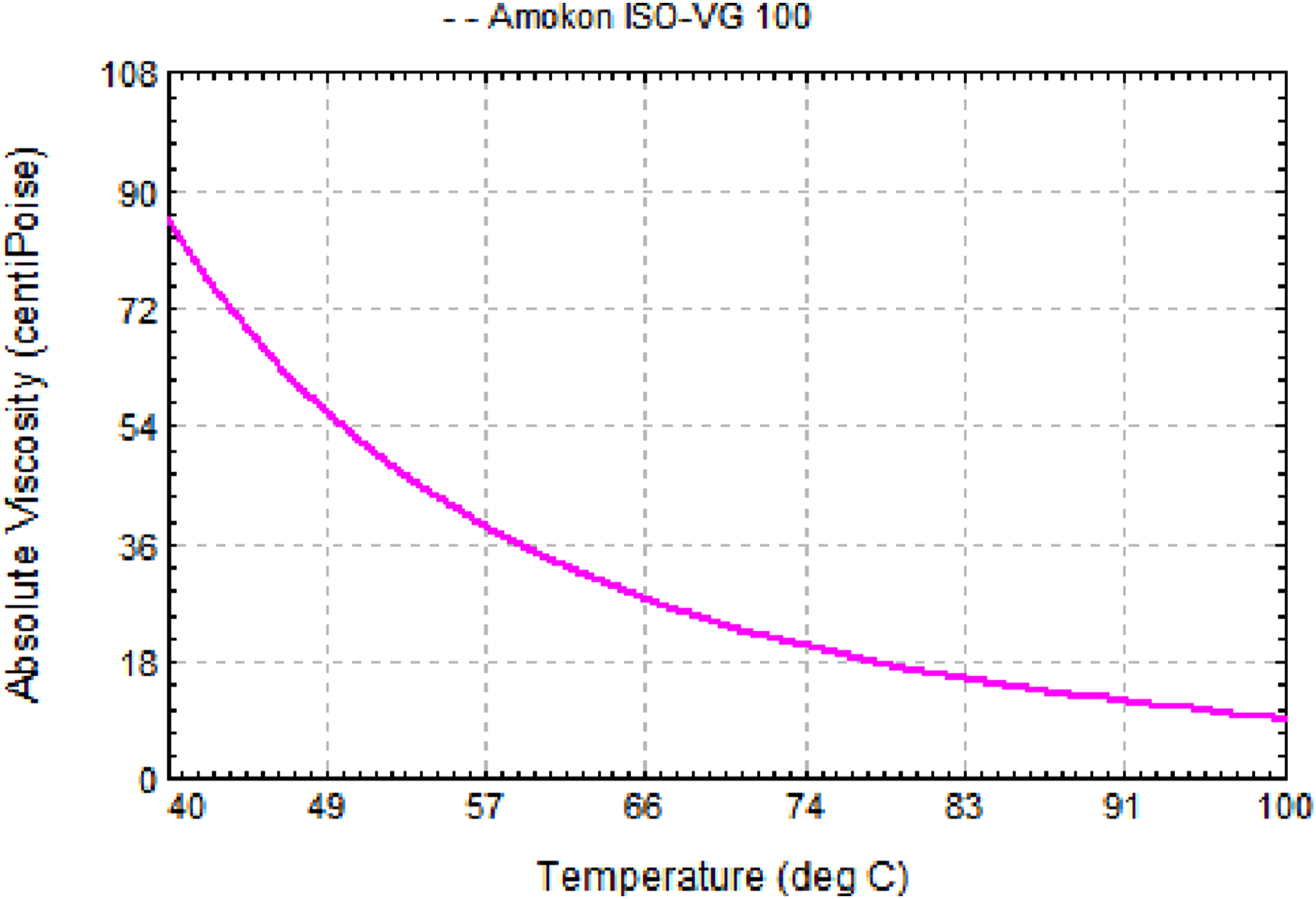

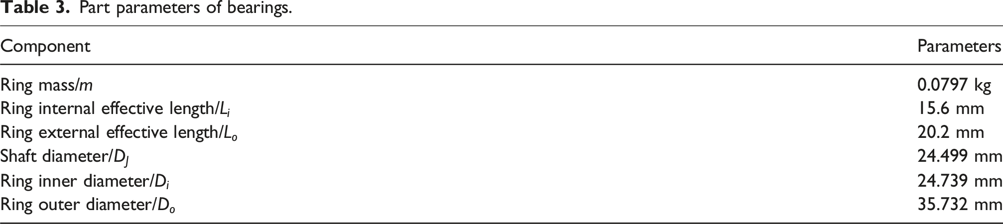
Part parameters of bearings.
Dynamic modeling of SFRB-TC rotor system
The governing equations of motion for a SFRB-rotor system at a constant speed Ω
27
:


The TC turbine is connected to the shaft by friction welding, and the compressor impeller is matched with the shaft end by interference and fixed by nut at the shaft end. The turbine material is steel, and the compressor impeller material is aluminum alloy.
By properly and reasonably simplifying the rotor structure, it includes 6 main units and 42 sub-units. Nodes 8 and 9 represent the compressor and turbine end floating rings, respectively, with a mass of 0.0797 kg. Near the position of node 5, the red mark near the turbine end bearing indicates the position of the rotor center of gravity. Therefore, the static load of the turbine end bearing is much larger than that of the compressor impeller end bearing. The red arrow indicates the applied unbalance, which is applied to the trailing edge of the impeller and turbine according to the actual situation. The established SFRB-TC rotor system model by DyRoBeS® is shown in Figure 4. Dynamic model of SFRB-TC rotor.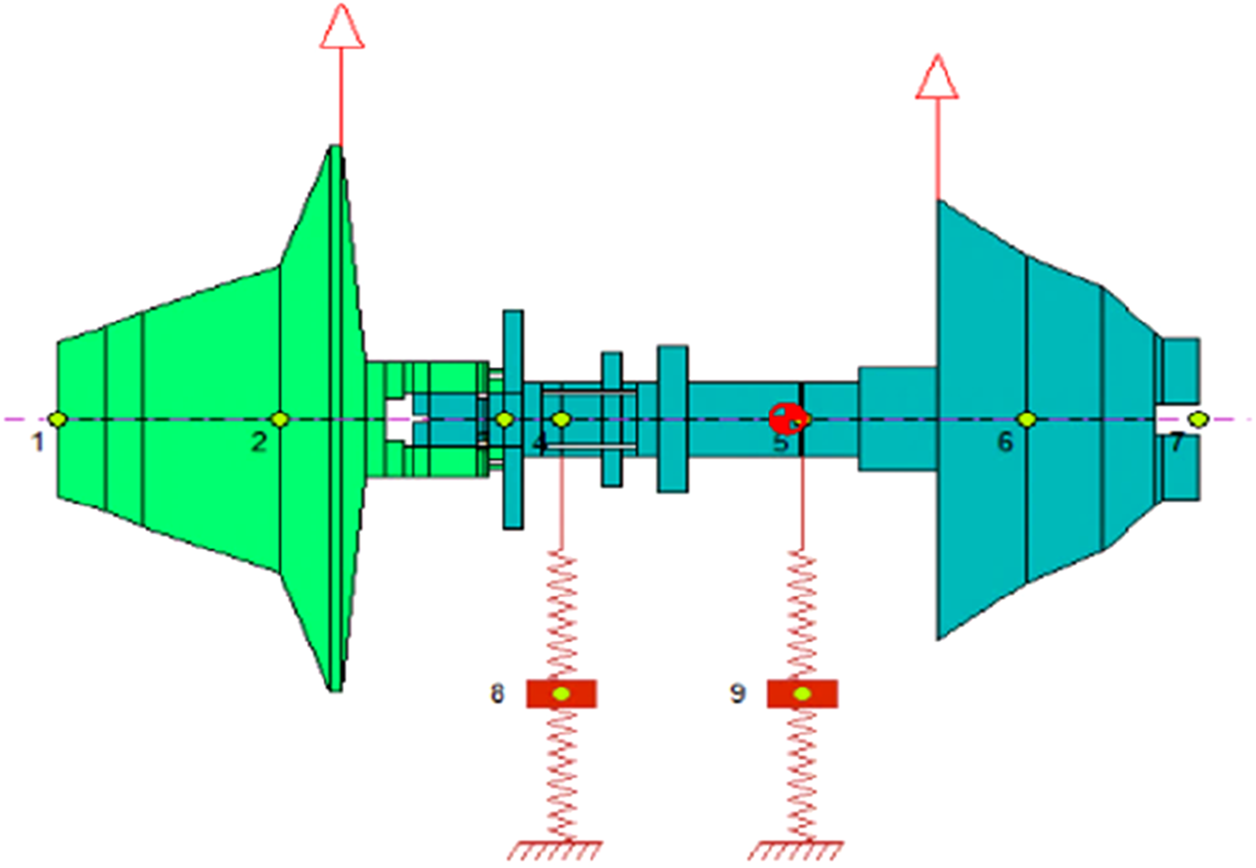
The model of the rotor system do not consider the three-dimensional temperature distribution. Based on actual operating experience, a proportion of the heat lost by the lubricating oil medium is calculated. Of all, 80% of the heat in the rotor system is dissipated through the lubricating oil heating end. The system is calculated based on the entire amount of heat. Regarding the lubricating oil ISO VG-100, its density changes with temperature during the operation of the rotor. However, the change in density is very small. Therefore, it is assumed that the oil film density in the study does not change.
Procedure
Validation of finite element model of TC rotor
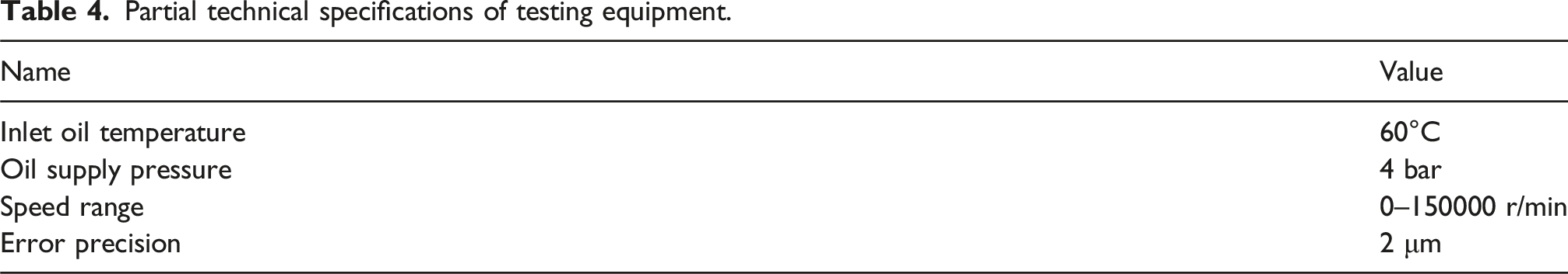
Partial technical specifications of testing equipment.
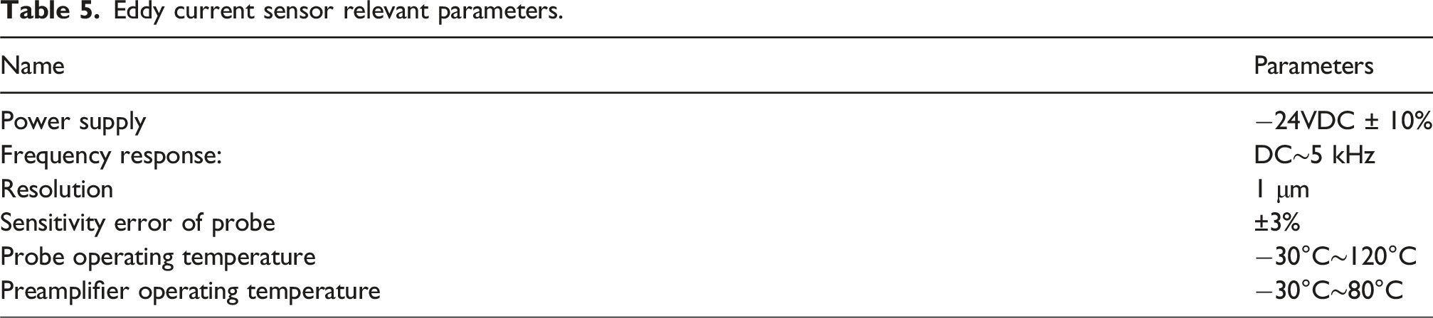
Eddy current sensor relevant parameters.
On the TC test bench, the axis trajectory test device and the axis average position test devices were used to carry out the test. According to the special requirements of the test, the test hole was redesigned on the bearing shell. The bearing shell was specially designed to prevent instrument damage. Two non-contact eddy current sensors were placed at 90° each other. The axis trajectory of the rotor relative to the base in their respective directions was measured. The signals detected in the two directions were combined to obtain the shaft center trajectory of the rotor. The layout of sensors and the TC test bench are shown in Figure 5. Experimental device diagram.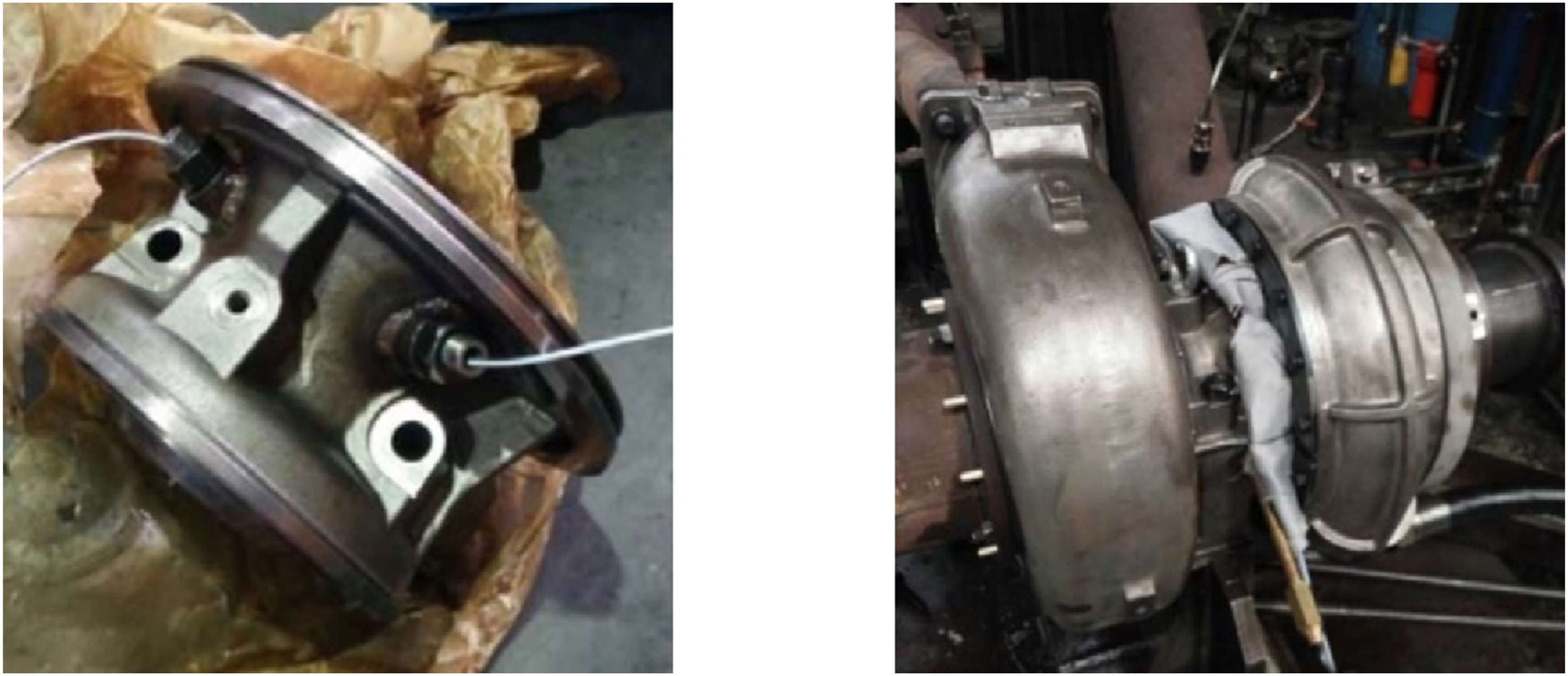
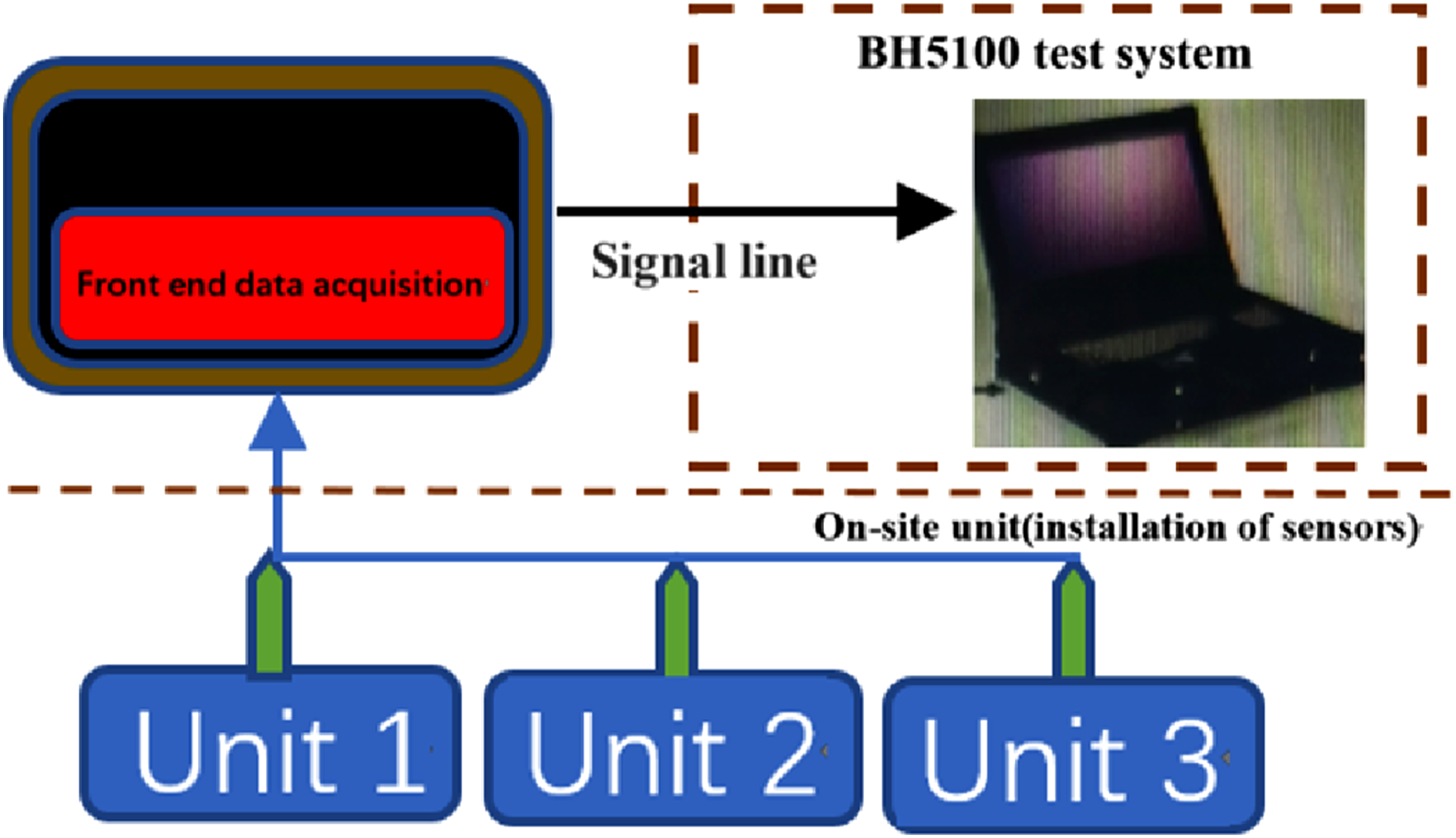
Because the focus of the research is not related to the high temperature condition, the turbine adopts the cold air driving mode. The driving power is provided by the air compressor. The bearings are lubricated by a circulating oil supply system. Capture sensor output signals through a data acquisition card. The signals collected by the eddy current sensor installed on the specially designed bearing shell are processed and analyzed by the BH1500 system. Then generate an axis trajectory map. The principle flow chart of the TC rotor test system is shown in Figure 6. The BH1500 test system is shown in Figure 7. The flow chart of experiment. BH1500 test system schematic diagram.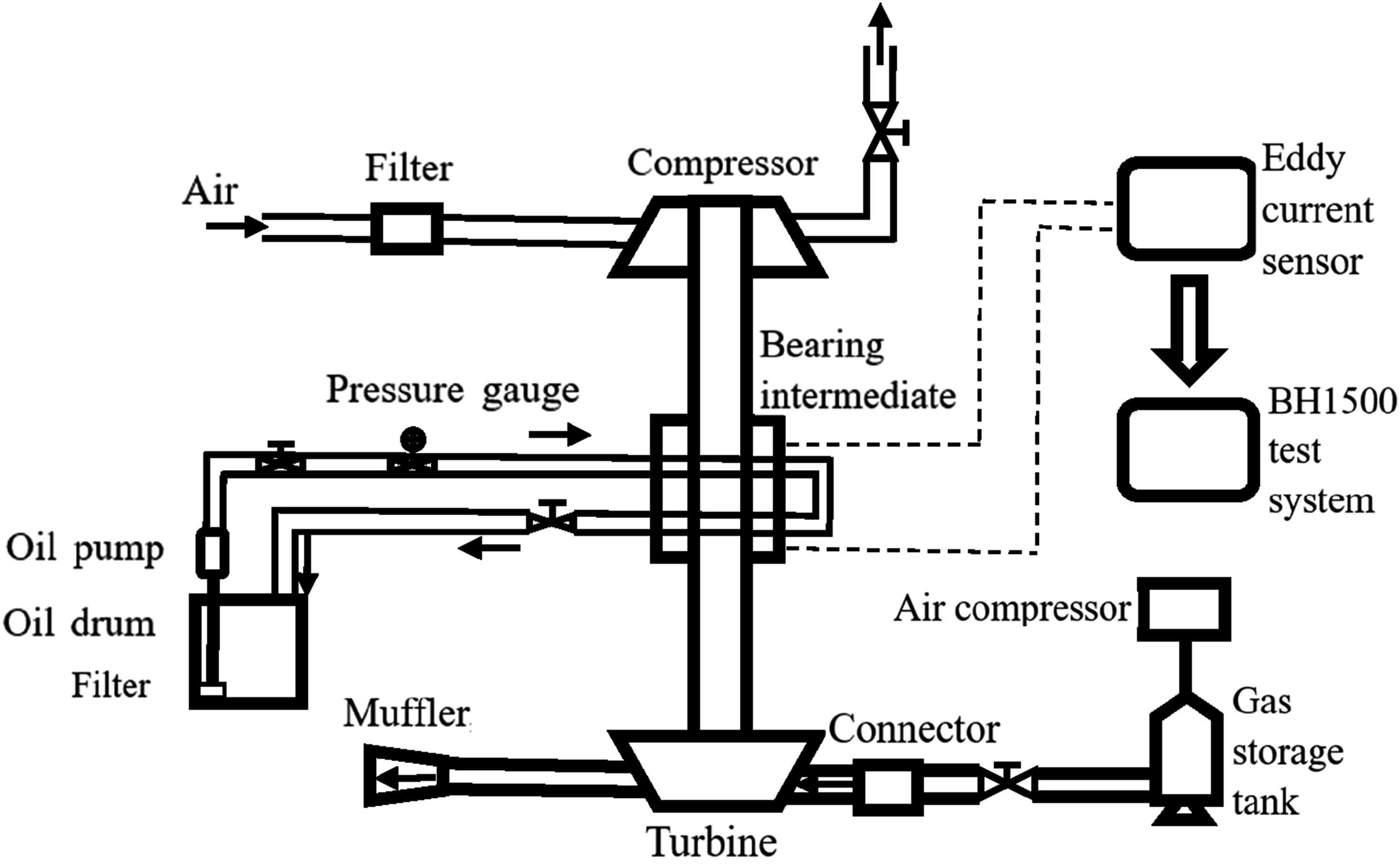
According to the engine operating conditions, the operating speed range of this type of turbocharger is roughly between 30,000 r/min and 60,000 r/min. In this speed range, the axis trajectory was measured to ensure more accurate results, reasonable distance between the measured speed points, and more representative test results. Therefore, the axis trajectory of the rotor is measured every 5000 r/min. The TC model was simulated and calculated. Compared with the axis orbit of the bearing position at each corresponding speed, the test and simulation results are in good agreement. Among them, at high speeds, the test 59,965 r/min axis trajectory results and simulation results are shown in Figure 8. The unit of the experimental result is μm, and the unit of the simulation result is mm. High-speed axis trajectory test and simulation results. (a) 59,965 r/min test results and (b) 60,000 r/min simulation results.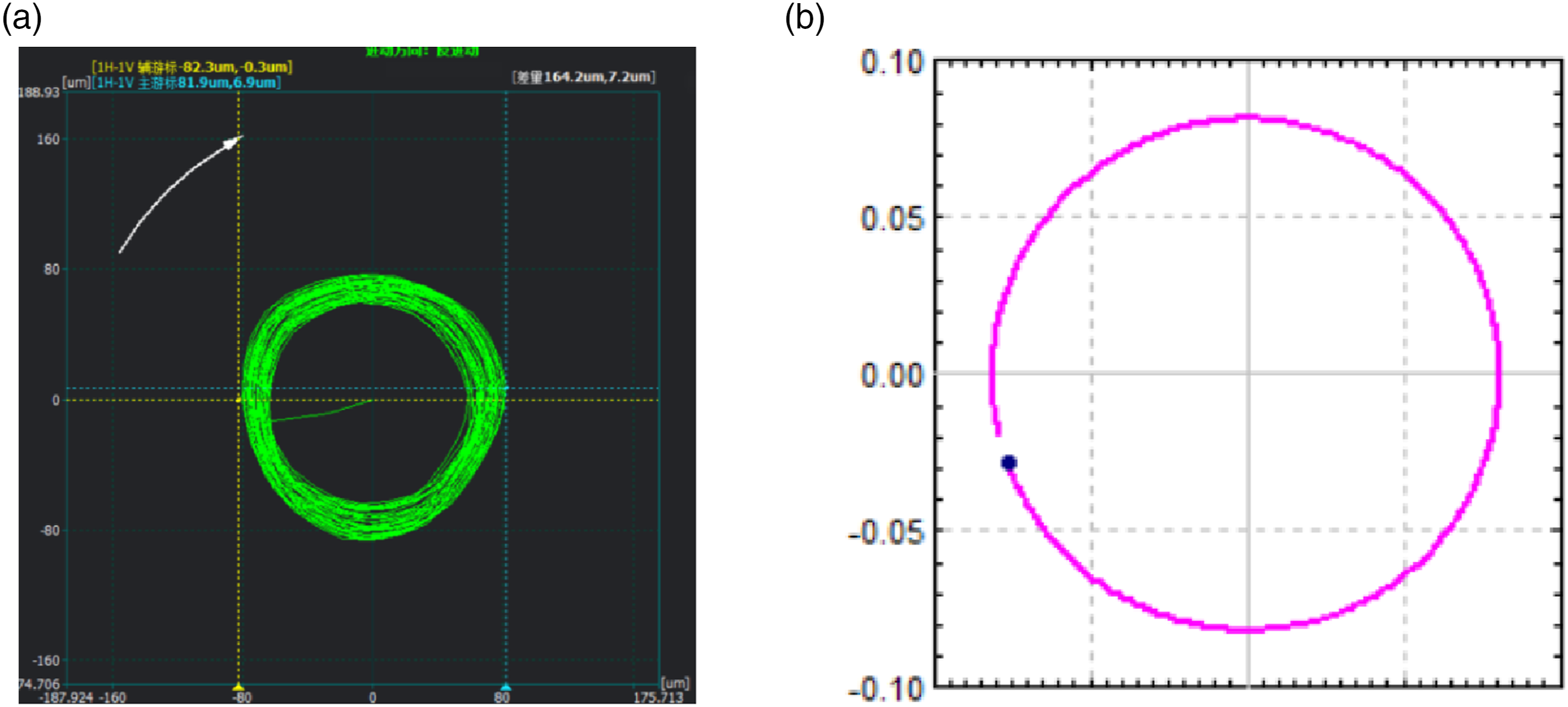
Rotor dynamics design of EAT rotor
The basic parameters of the motor rotor.
The material characteristics of the motor rotor.
Among them, the motor rotor material is the same as the turbine material. On the basis of the original TC machine, the EAT rotor was designed in combination with the above structural parameters. The dynamic finite element model of the SFRB-EAT rotor system was established as shown in Figure 9. Finite element model of motor front-mounted electric-assisted TC.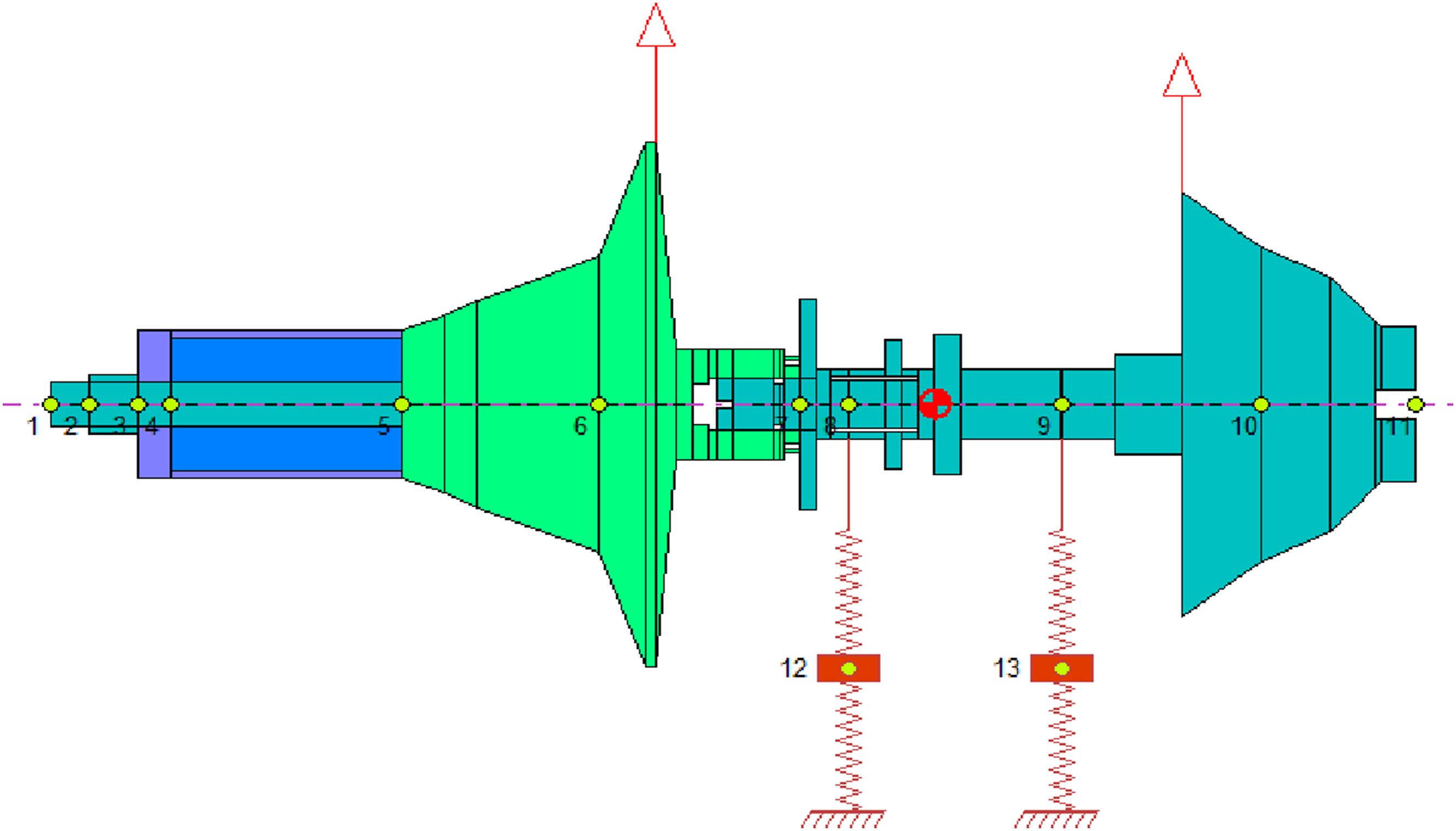
Results and discussion
Comparison of EAT and TC linear analysis
Due to the unique double-layer oil film structure characteristics of the floating, in the linear analysis, its external oil film does not produce oil film pressure in the steady-state state, which becomes the relationship between the floating sleeve and the journal. The calculation model is expressed in the form of three-lobed fixed bearing. For the modeling data of this part of the bearing, the structural parameters, load, and lubrication conditions of the three-lobe bearing were input through the bearing module of the software. The journal speed was calculated to be 5000 r/min to 80,000 r/min, and the step was 5000 r/min. The stiffness and damping coefficients of the bearings at the compressor and the turbine ends were obtained and imported into the rotor module for bearing modeling. In order to better understand the nonlinear simulation results, the linear analysis was carried out first. The dynamic analysis of the designed EAT rotor and the original rotor were carried out and compared.
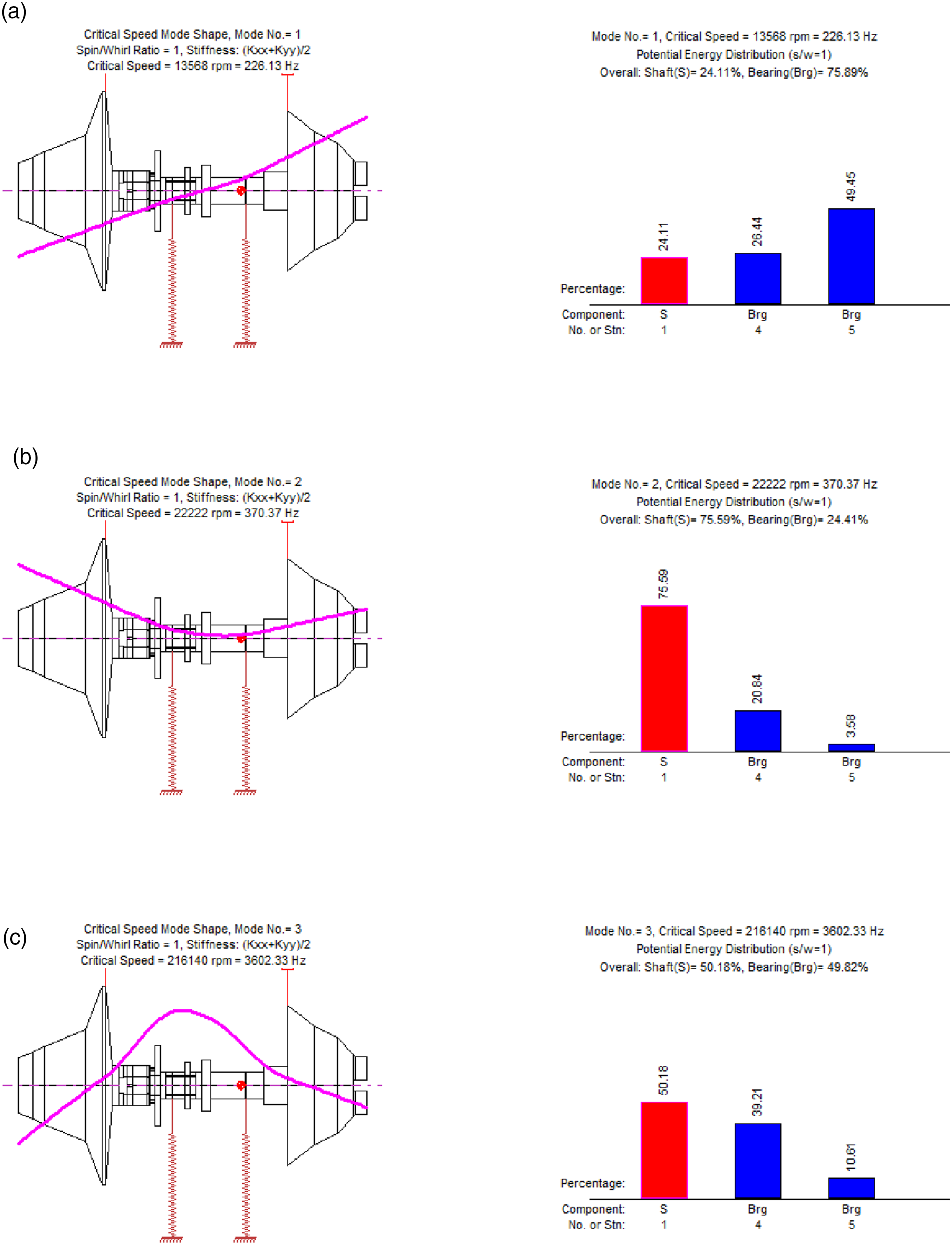
Figure 10 shows the first three critical speed vibration modes and the corresponding strain energy distribution of the original TC rotor. As can be seen from Figure 10: a. The first three critical speeds of TC rotor are 13,568 r/min, 22,222 r/min and 216,140 r/min, respectively. The first order is the rigid conical vibration mode. The second order is the rigid cylindrical vibration mode. The third order is a typical bending mode. b. When the TC rotor is at the first-order critical speed, the strain energy distribution of the turbine end bearing reaches 49.45%. The reason is that the turbine end bearing bears a higher load, which can also be seen from the center of gravity position of the model. At this time, more attention needs to be paid to the operating conditions of the bearing. c. Near the second-order critical speed, the shaft shows a fairly high strain energy distribution, reaching 75.59%. This is due to the high speed, the shaft changes in the modal shape, and more attention needs to be paid to the fatigue bending of the shaft system. At this speed, the rotor should accelerate over the position to prevent more severe vibration from causing damage. d. Although the third-order critical speed is far more than the upper limit of the operating speed of the rotor, it can be seen that the strain energy distribution of the shaft reduces, which is due to the good damping effect of the oil film bearing. The first three modes of TC and the corresponding strain energy distribution. (a) The first-order critical speed of TC and the corresponding strain energy distribution; (b) the second-order critical speed of TC and the corresponding strain energy distribution; and (c) the third-order critical speed of TC and the corresponding strain energy distribution.
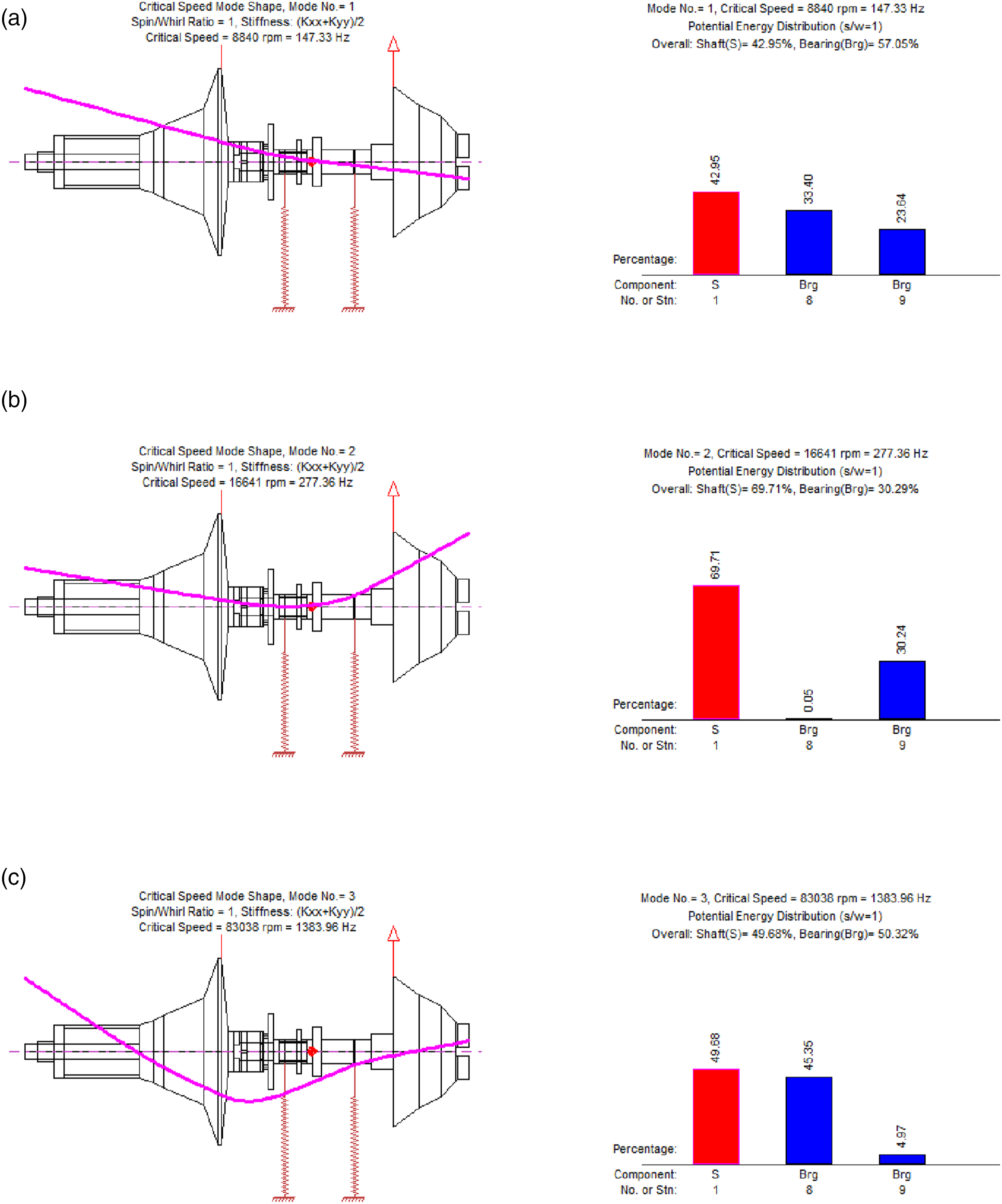
Compared with the TC rotor, the EAT rotor presents different results. Figure 11 shows the first three critical speed modes and the corresponding strain energy distribution of the designed EAT. According to Figure 11 and the above analysis, it can be seen that: a. The first three critical speeds of the EAT rotor are 8840 r/min, 16,641 r/min, and 83,038 r/min, respectively. b. Compared with the TC, the vibration mode of the rotor is consistent. But the difference is that the strain energy distribution on the shaft has been high, especially at the second critical speed position, the potential energy on the shaft reaches 69.71 %. At this time, the shaft will vibrate violently, which also corresponds to the research results in next chapter 3.2. Therefore, it is necessary to consider the selection of bearing parameters to reduce the amplitude of the shaft. The first three modes of EAT and the corresponding strain energy distribution. (a) The first-order critical speed of EAT and the corresponding strain energy distribution; (b) the second-order critical speed of EAT and the corresponding strain energy distribution; and (c) the third-order critical speed of EAT and the corresponding strain energy distribution.
The Campbell diagrams of TC and EAT rotors corresponding to the above results are shown in Figure 12. The intersection points of 1X line and each forward precession line are the critical speed of each order, which corresponds to the above analysis. The shadow part in the figure is the working speed range of the journal 30,000 r/min–60,000 r/min. Through the Campbell diagrams, it can be seen that the designed EAT rotor runs farther away from the second-order critical speed within the operating speed range, ensuring sufficient safety margin. Campbell diagrams of TC and EAT rotors. (a) TC rotor and (b) EAT rotor.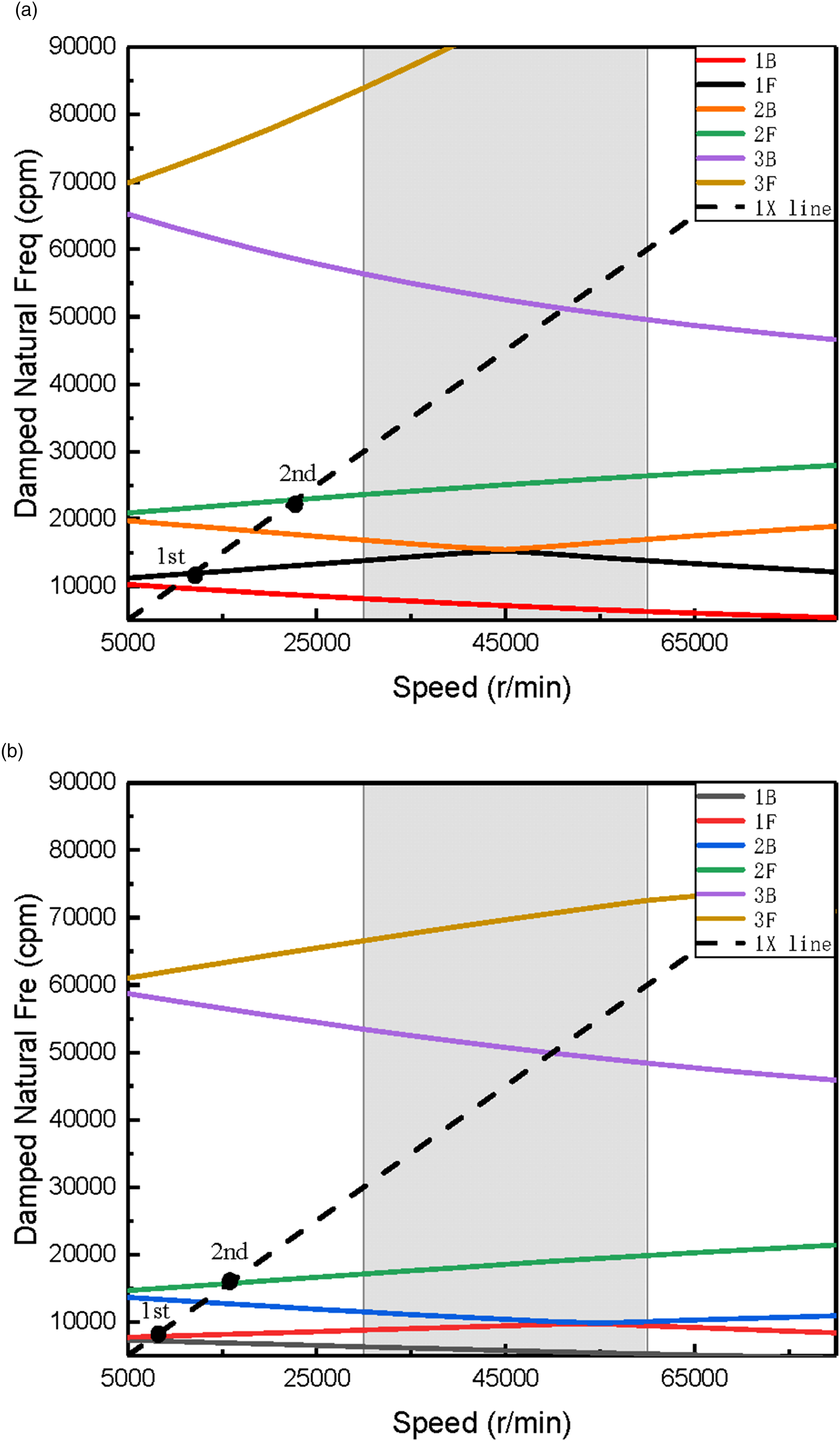
The stability diagrams of TC rotor and EAT rotor after linearization are shown in Figure 13. There is no instability mode at low speed. TC rotor has two instability modes at high speed, while EAT rotor has only one instability mode at high speed. The instability threshold of the EAT rotor is about 16,000 r/min. In fact, for the EAT rotor supported by SFRBs, from low-speed motion to equilibrium position, when gradually accelerating, the rotor dynamic behavior is quite complex due to the whirl/whip of the oil film, which depends on the parameters in the system. Stability diagrams of TC and EAT rotors. (a) TC rotor and (b) EAT rotor.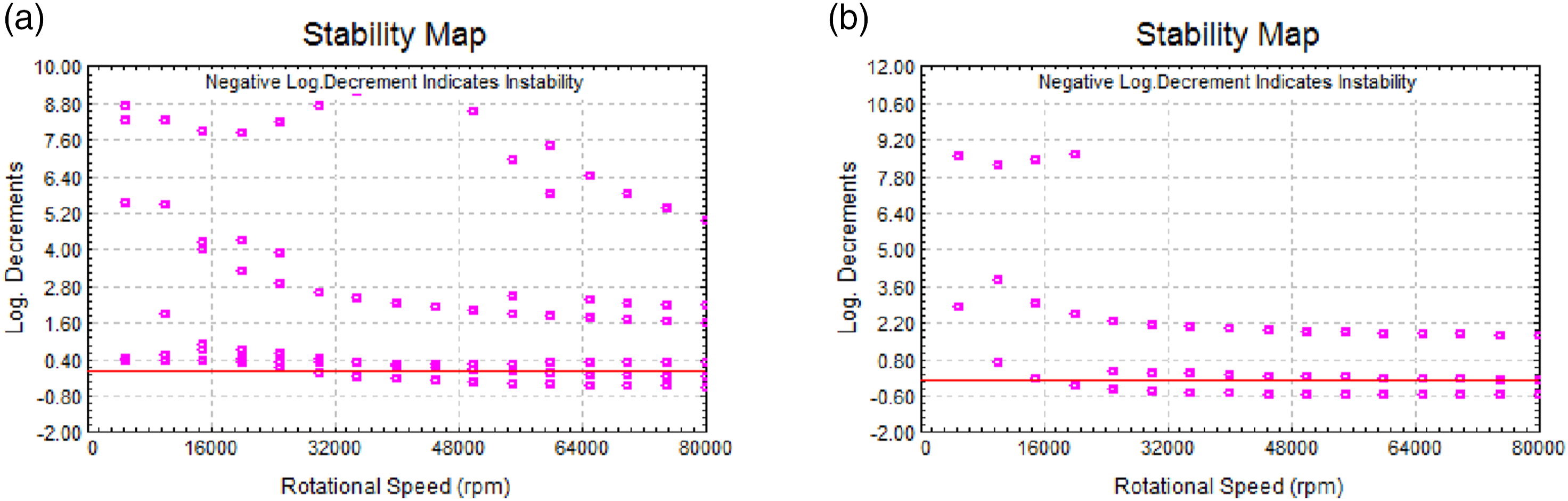
Nonlinear numerical simulation
In order to predict the complete motion of the EAT rotor, a time transient analysis is required. Compared with automotive TCs, the dynamic characteristics of the marine TC rotor are closely related to unbalance. In addition, due to the influence of oil film, the self-excited vibration of the rotor occurs during operation. Therefore, due to the coupling effect of gravity and unbalanced excitation and lubricating oil film, the vibration response and its variation law of the EAT rotor are extremely complex.
Considering that the change of the SFRB clearance will directly affect the lubricating oil film. The self-excited vibration caused by the nonlinear oil film force has a great influence on the rotor vibration, it is necessary to fully study the nonlinear dynamic behavior of the EAT rotor. The time transient analysis is carried out in the speed range of 10,000 r/min to 80,000 r/min. The Newmark-beta method is used as the solution method to determine the influence of the internal clearance change on the dynamic characteristics of the rotor.
Effect of internal clearance variation on normal EAT rotor dynamics
To analyze the vibration of rotating machinery, order analysis is an important content, which is inseparable from the response spectrum density analysis. The horizontal axis of the diagram represents the rotational speed, and the vertical axis represents the frequency. It can reflect the change rule of the signal with the rotational speed and frequency. The depth of the color represents the signal amplitude, red represents the maximum value, and blue represents the minimum value. Figure 14 describes the simulation results of the node 1 position of the normal rotor under the change of the internal clearance. Response spectral density of normal rotor with different internal clearances. (a) 0.105 mm; (b) 0.210 mm; (c) 0.315 mm; and (d) 0.420 mm.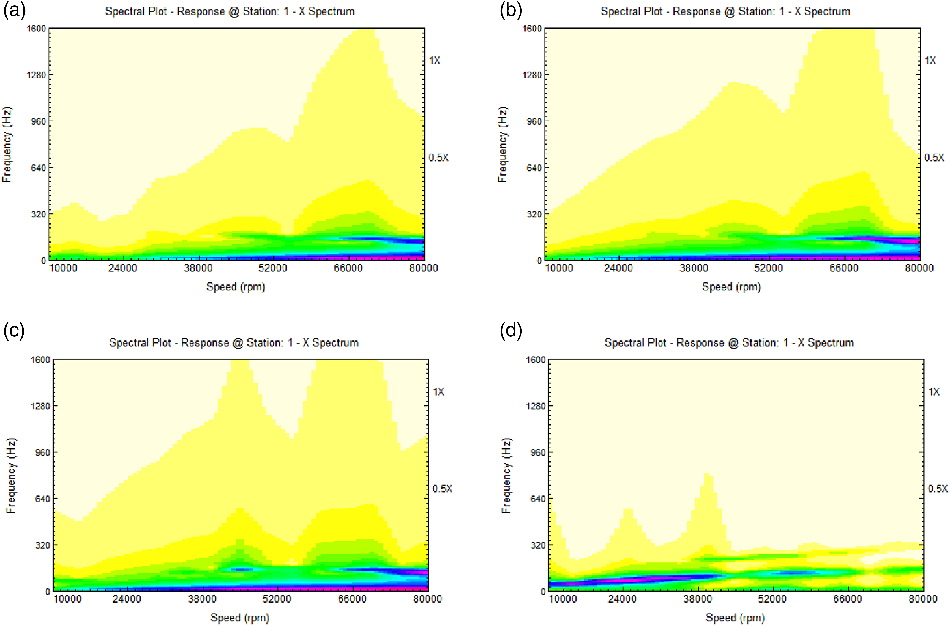
The simulation results are summarized as follows: a. From the first three figures in Figure 14, it can be seen that the studied system becomes unstable at 60,000 r/min. The sub-synchronous vibration caused by unstable oil film persists after this speed, and the rotor vibration is dominated by it. b. When the internal clearance is 0.315 mm, within the speed range of EAT operation, there is a brief occurrence of sub-synchronous vibration component from 43,000 r/min to 47,000 r/min. c. As shown in Figure 14(d), the rotor exhibits high amplitude sub-synchronous vibration continuously from the simulation until 43,000 r/min with a large clearance. And the sub-synchronous vibration reappears at 50,000 r/min–60,000 r/min, but the amplitude decreases slightly. The rotor exhibits intermittent stability during this process. d. Within the simulated speed range, the rotor has a wide range of 0 Hz vibration frequencies, which has not been observed in other studies. The author explains it as the “DC” phenomenon, which is an inherent characteristic of SFRB normal rotor systems. The rotor is in a state of vibration equilibrium only when this phenomenon exists.
Because of the high sub-synchronous vibration of the rotor at high speed in the whole speed range, Figure 15 lists the axis trajectory of the normal rotor node 1 at 80,000 r/min when the internal clearance is different. From the diagram, it can be seen that the trajectory of the rotor axis in the smaller internal clearance range is not much different. The trajectory of the rotor in the larger internal clearance is slightly different, which is consistent with the previous part. Axis orbit of normal rotor with different internal clearances. (a) 0.105 mm; (b) 0.210 mm; (c) 0.315 mm; and (d) 0.420 mm.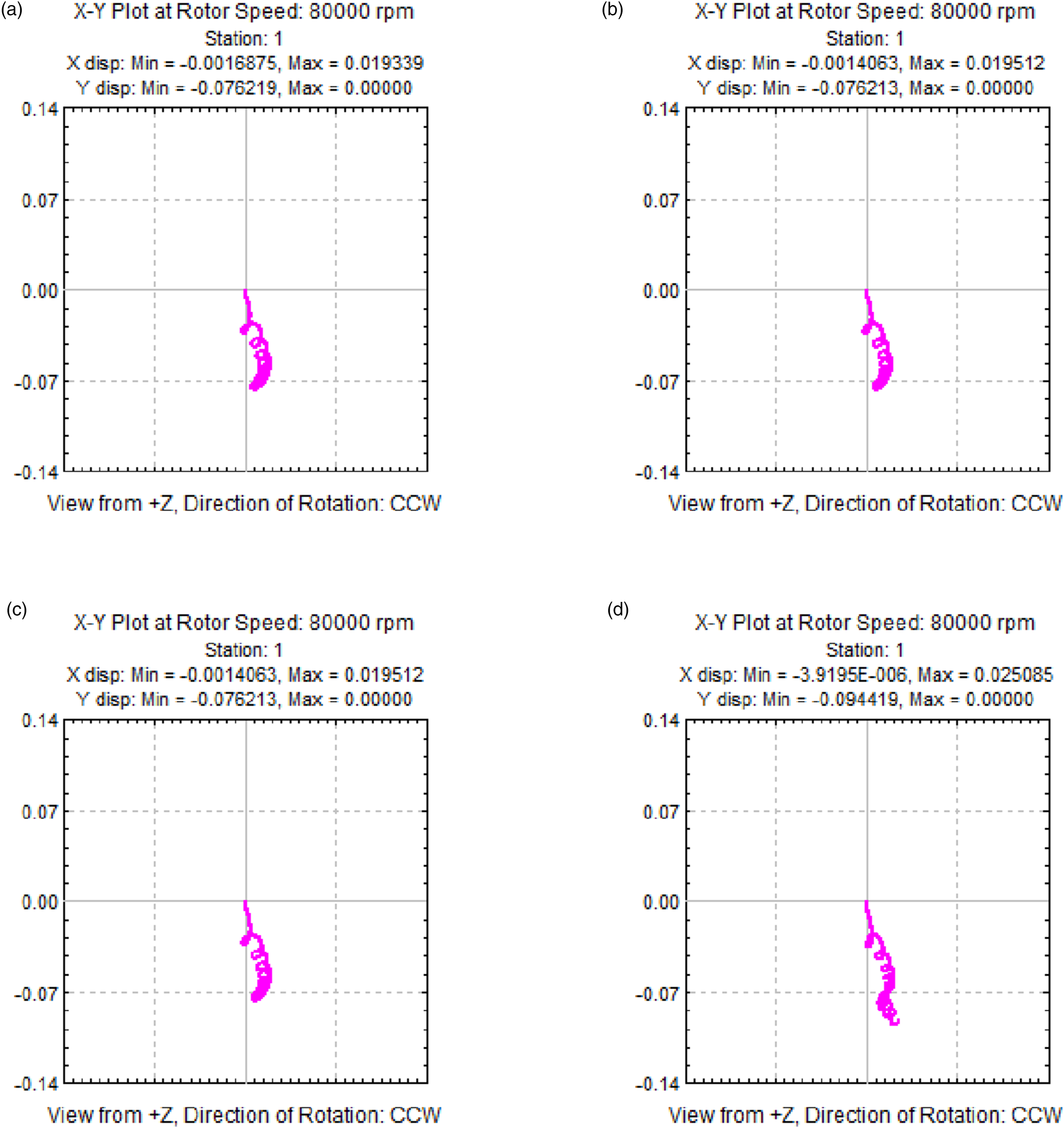
Effect of internal clearance variation on rotor dynamics of unbalanced EAT
As shown in the previous chapter on the normal rotor, the rotor will produce very high sub-synchronous vibration during operation. The vibration caused by unbalance will inevitably affect this self-excited vibration behavior. Therefore, it is necessary to further study the impact of unbalance on the rotor and predict the dynamic characteristics of the actual rotor. The vibration response evolution law of unbalanced rotor with increasing speed during internal clearance changes was analyzed and discussed. Figure 16 shows the vibration response of an unbalanced rotor with varying internal clearances. Response spectral density of unbalanced rotor with different internal clearances. (a) 0.105 mm; (b) 0.210 mm; (c) 0.315 mm; and (d) 0.420 mm.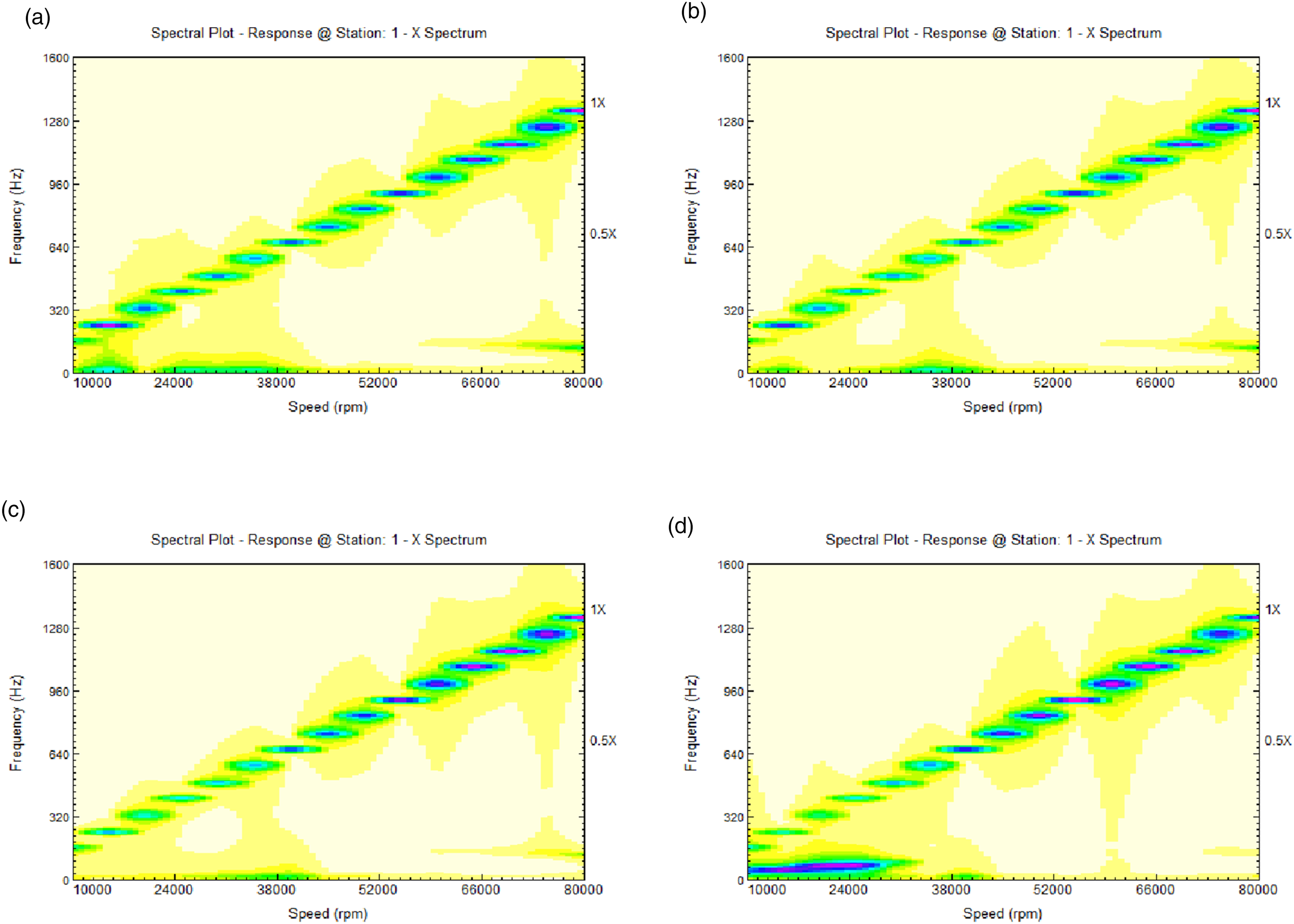
The conclusions of the results are as follows: a. As mentioned above, sub-synchronous can also be observed in the response spectrum. In addition, the frequency components under different internal clearances are basically consistent with the results in section 3.2.1. However, there is no large-scale “DC” phenomenon. b. When the internal clearance is 0.105 mm, slight sub-synchronous vibration occurs after 12,000 r/min–17,000 r/min and 71,000 r/min. As the internal clearance increases, the phenomenon of sub-synchronous vibration disappears at low speeds, and the initial speed increases at high speeds. c. Except for the case where the internal clearance is 0.420 mm, the rotor exhibits a relatively high synchronous vibration amplitude at a low speed of 16,000 r/min. And the critical speed at this position must be considered to accelerate the rotor through this position to prevent larger faults. d. It is obvious that the 16,000 r/min speed position corresponds to section 3.1. This indicates that although the system has obvious nonlinearity, linear analysis can effectively predict the response of synchronous rotors. e. Meanwhile, Figure 16 shows an interesting phenomenon. As the internal clearance increases, synchronous vibration significantly decreases at low speeds, while sub-synchronous vibration shows a first decrease at high speeds and then a significant increase at low speeds. f. It is worth noting that in the study, when the internal gap was 0.315 mm, there was no strong sub-synchronous vibration observed at low speeds within the operating speed range. In addition, the synchronous amplitude is relatively low. Can be used as a design reference.
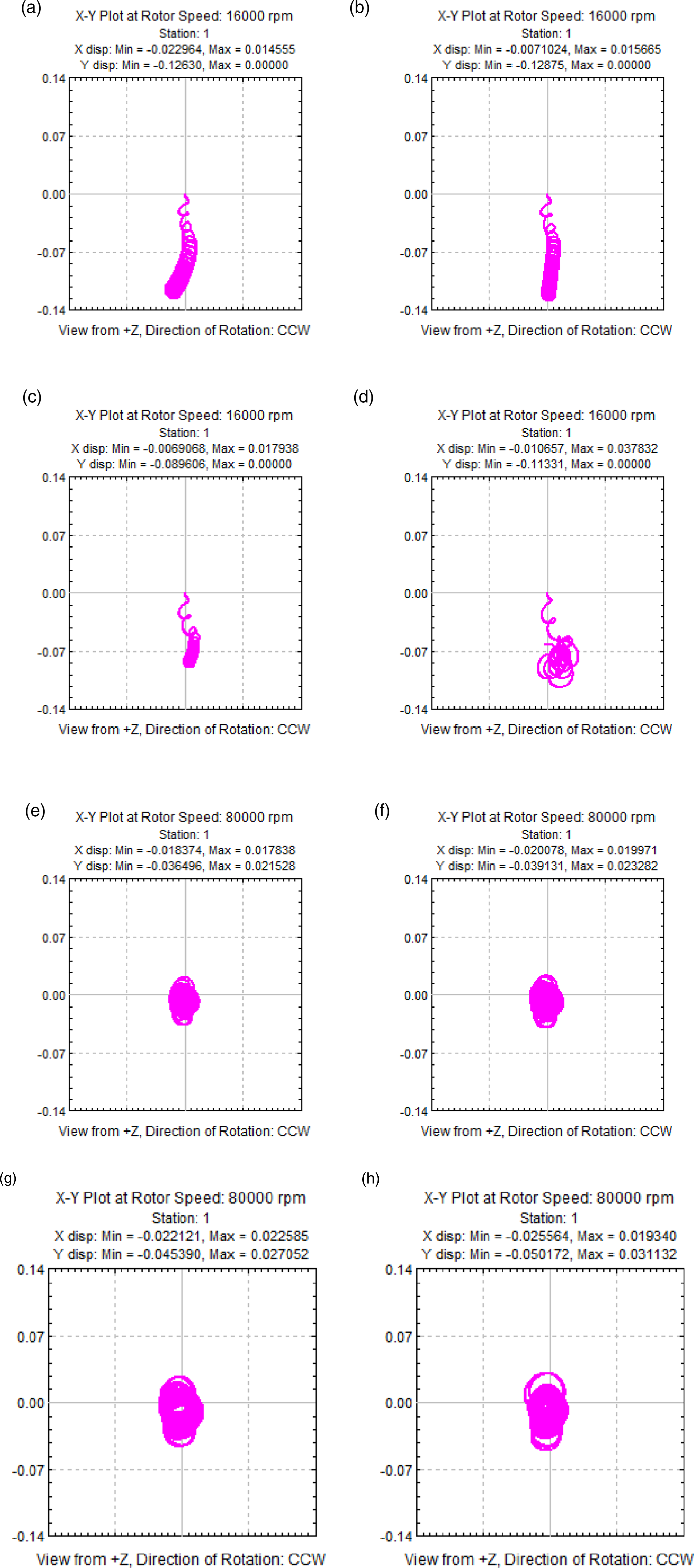
For the vibration response of node 1 at 16,000 r/min and 80,000 r/min, the time domain analysis is carried out, and the axis trajectory is shown in Figure 17. The conclusions are as follows: a. From Figure 17(a) and (b), it can be seen that when the internal clearance is small, the shape of the rotor trajectory at the 16,000 r/min position is roughly the same. And the axis trajectory moves downwards, exhibiting linear characteristics. The reason is that the influence of weight load, the axis trajectory moves downward until the oil film force is equivalent to the gravity load, and the axis position stabilizes. b. Similarly, at a speed of 80,000 r/min, there is almost no difference in the axis trajectory under small clearances, and the radius size difference is also not significant. As the clearance increases, the operating trajectory of the rotor gradually tends toward a bounded limit cycle (BLC). c. Observing Figure 17(d) and (h), differences are observed in the presence of excessive internal clearances. At 16,000 r/min, the rotor motion exhibits a chaotic state, which can also be attributed to the analysis in Figure 16(d). d. From the trajectory radius at high and low speeds in various situations, it can be seen that the rotor has a greater axis offset at low speeds. As the speed increases, the rotor moves toward the central axis position, and the radius of the axis trajectory decreases. e. At high speeds, the rotor exhibits nonlinear characteristics. The rotor no longer runs to the equilibrium position at low speed but is in a state of balance and motion. Currently, the rotor undergoes periodic closed-loop motion, and the axis trajectory exhibits multi-ring characteristics. The rotor runs on BLC. f. Relatively speaking, in the time domain analysis considered, Figure 17(c) and (g) demonstrate excellent stability in the trajectory of the rotating axis. The axis trajectory of the unbalanced rotor with different internal clearances: (a and e) 0.105 mm, (b and f) 0.210 mm, (c and g) 0.315 mm, and (d and h) 0.420 mm.
Discussion
Sections 3.2.1 and 3.2.2 analyze the vibration of their respective rotors and evaluated the corresponding axis trajectories. This chapter compares the above analyses and further discusses the phenomena and causes. The details are as follows:
Firstly, the EAT rotor without considering external excitation exhibits higher amplitude sub-synchronous vibrations owing to oil film oscillations caused by nonlinear oil film forces. Especially at 0.420 mm, the performance is significant. The rotor exhibits oil film instability at low speeds. When the internal clearance is small, the rotor experiences oil film oscillation at high speeds. Due to the absence of external excitation, rotor vibration is completely controlled by gravity and nonlinear oil film forces. At the same time, by the coupling effect of gravity and oil film force at low speeds, the trajectory axis shows significant deviation and downward movement. As the speed increases, the self-excited vibration caused by the oil film force dominates the rotor vibration, and the trajectory moves upward.
Secondly, there are certain differences in the sub-synchronous vibration trend between SFRB rotors with unbalanced excitation and normal rotors. The main differences are as follows: a. The sub-synchronous vibration range of the unbalanced rotor is greatly reduced. Comparing Figures 14 and 16, the sub-synchronous vibration phenomenon has been effectively suppressed. When the internal clearance increases from 0.105 mm to 0.315 mm, the magnitude of the sub-synchronous vibration is weakened. At the same time, its initial speed of appearance gradually increases. When the internal clearance is 0.420 mm, the upper limit speed of sub-synchronous vibration is reduced from 43,000 r/min to 28,000 r/min. Effectively avoiding the operating speed range, this reflects the suppression effect of synchronous vibration on the sub-synchronous vibration of small clearance rotors. b. The trajectory of unbalanced rotor motion exhibits similar linear characteristics at low speeds. It should be noted that when the inner clearance is large, bearings become very unstable at low speed, and the oil film turbulence intensifies. Meanwhile, attention should also be paid to the increase of synchronous vibration amplitude. The rotor rotates in a conical mode, and the system is prone to rotor-stator friction. Continuing to operate in this state will seriously affect the service life of EAT.
Finally, for EAT unbalanced rotor, the reasons for the sub-synchronous vibration phenomenon variation when the SFRB clearance of the changes are analyzed. a. As the clearance increases from 0.105 mm to 0.315 mm, the initial velocity of sub-synchronous vibration will increase at high speeds. This is due to changes in the dynamic characteristics of the oil film, with significant sub-synchronous vibration phenomena at high speeds. At this point, the high-speed rotor is subjected to greater centrifugal inertia force, which affects the distribution and stability of the oil film within the clearance. The larger the internal clearance, the easier it is to form whirl, but this whirl requires a higher initial velocity to exist stably. In addition, it must be recognized that the increase in clearance reduces the stiffness of the oil film, further affecting the occurrence of sub-synchronous vibration at high speeds. b. Sustained strong sub-synchronous vibration occurs when there is an excessively large internal clearance. At low speeds, the rotor experiences less centrifugal force, and the lubricating oil cannot fully fill the clearance, resulting in the rotor being unable to be effectively supported by the oil film. The rotor will experience “shaking” within the bearing clearance. This “shaking” further exacerbates the instability of the oil film, resulting in severe sub-synchronous vibration. In addition, excessive clearance also reduces the bearing’s load-bearing capacity. The radial load of the rotor cannot be effectively resisted, which is also beneficial for exacerbating sub-synchronous vibration.
Therefore, the internal clearance of SFRB will have a significant impact on the vibration of EAT rotor. Reasonable consideration of the clearance inside the bearing is beneficial for ensuring the stability of the EAT rotor during operation. In this study, it is recommended to maintain the internal clearance at around 0.315 mm, as the rotor has good performance.
Conclusions
In order to further improve the performance of the TC and realize the electrification of the ship power system, the dynamic design and analysis of the rotor-bearing system of the EAT are carried out in this research. The finite element model of the original TC rotor is established by rotor discretization. The effectiveness of the modeling method is verified based on the experimental data. Based on the linear analysis, the time transient analysis is further carried out to reveal the vibration law of the EAT rotor with the change of internal clearance and rotational speed. The main conclusions are as follows: 1. The linear analysis results of EAT rotor and TC rotor are significantly different. The critical speed of the EAT rotor is lower than that of the TC rotor, and the EAT rotor shaft at each critical speed position has a higher potential energy distribution, which leads to more severe vibration and makes the rotor unstable in a linear sense. 2. Due to the damping effect of the internal oil film, the EAT rotor runs stably under a small internal clearance. However, as the speed increases, the nonlinear oil film force causes higher self-excited vibration, and the rotor becomes unstable at high speeds. High sub-synchronous vibration has a greater impact on the rotor. 3. With the change of internal clearance, the stability trend of unbalanced rotor is almost the same as that of normal rotor, and it is relatively stable in the range of operating speed. The normal rotor has a “DC” phenomenon in the entire speed range. However, for the unbalanced rotor, this phenomenon almost disappears. In addition, due to the existence of unbalance, the sub-synchronous vibration at high speed is not as severe as that of normal rotor. 4. The internal clearance should be controlled within a reasonable size range. The larger internal clearance affects the distribution and stability of the oil film, resulting in high sub-synchronous vibration at low speed. To suppress the instability of the EAT rotor and reduce the amplitude, it is recommended to stabilize the internal clearance of the rotor-bearing system at about 0.315 mm. 5. The research results provide a reference for the dynamic design of the EAT rotor. The proposed internal clearance size control can effectively suppress the asynchronous vibration component and reduce the total vibration level within the rotor design speed range. In addition, the study can further understand the nonlinear dynamics of the EAT.
Outlook
At present, the focus of the work is to study the vibration response characteristics of EAT with the change of internal clearance to ensure the stability of rotor operation. It must be recognized that there are various factors that affect the EAT rotors, such as the external clearance oil film that is completely different from the rotating inner film. It is necessary to study the impact of various influencing factors on the EAT rotors, study the reasonable configuration between the main influencing factors to ensure the operational stability. Subsequently, the rotor will undergo physical design and manufacturing. An EAT rotor test bench will be built to measure its stability through experiments, providing theoretical support and experimental reference for the dynamic design and analysis evaluation of EAT.
Footnotes
Acknowledgments
The authors appreciate all experts and workers participated in this study.
Statements and declarations
Funding
The authors disclosed receipt of the following financial support for the research, authorship, and/or publication of this article: The research was supported by the Doctoral Research Innovation Fund Project [3072023GIP0303] and central universities’ basic research business fees.
Conflicting interests
The authors declared no potential conflicts of interest with respect to the research, authorship, and/or publication of this article.