
Abstract
To study the potential application of the longitudinal vibration control of a rod coupling system by employing NESs, this study proposes a nonlinear vibration reduction coupler (NVRC), where the NVRC can be regarded as the NES which is installed between the two elastic structures. The introduction of NVRC is aimed at controlling the longitudinal vibration of the rod system. Based on the Lagrange method (LM), the longitudinal vibration analysis model of a rod system connected through a linear elastic coupler and an NVRC is established, in which the longitudinal vibration responses of the rod system with an NVRC are predicted. In the numerical analysis, the correctness and stability of LM in calculating longitudinal vibration responses of the rod system with an NVRC are verified, where the chosen reasons for observation points are explained. It can be concluded that the introduction of NVRC can reduce the vibration of each resonance area of the rod system at the same time. Under certain parameters, the vibration characteristics of the rod system are changed by employing NVRC. Furthermore, nonlinear stiffness and viscous damping of NVRC can be chosen as the adjustable parameters that strengthen the vibration reduction ratio of the rod system. Overall, the longitudinal vibration of the rod system can be effectively controlled by choosing reasonable parameters of NVRC. The introduction of NVRC provides an effective way to control the longitudinal vibration of the rod system.
Introduction
Structural vibrations are common in various engineering disciplines due to the appalment of power machinery and working conditions. These vibrational forces can have detrimental effects on the integrity and stability of engineering structures. It is crucial to comprehensively understand these vibrations and implement effective control measures. To simplify the analysis process, engineering structures are often conceptualized as assemblies of elemental units such as rods, beams, and plates. This approach facilitates a more systematic examination of the vibrational characteristics of the structures. By studying the vibrational properties of these elemental units, engineers can gain insights into the overall behavior of the entire structure.
In the field of machining engineering, boring bar systems are typically simplified as rods to study their vibration characteristics. To effectively control boring bar systems’ vibration, having a deep study of the vibration characteristics of rods plays an important role. Against this background, the research conducted by Tang et al. 1 shed light on the behavior of rods with complex boundary conditions. Pritz 2 delved into the dynamic strain of viscoelastic rods with added end masses, providing a deeper understanding of the factors influencing the structural vibrations. Gürgöze 3 took a meticulous approach to studying the specific frequencies of rod systems. Candan and Elishakoff 4 approached the study of rod systems from a different perspective. Instead of focusing on the vibration characteristics directly, they calculated the axial stiffness of rods based on their primary vibrational shapes. This approach provides engineers with a quantitative measure of the rods’ stiffness, enabling them to make informed decisions during the design process. Erol 5 addressed the characteristic equations for internally supported rod systems with an end mass. By deriving these equations, a mathematical framework for understanding the behavior of such rod systems was established. Mei 6 conducted a comprehensive analysis of four rod theories, significantly advancing the application of vibration theory in rod systems. Goldberg et al 7 studied the contact point motion of the rod system under a longitudinal vibration excitation. Considering the nonlocal continuum rod model, Aydogdu 8 studied axial vibration of the nanorod. Xu et al9,10 employed the improved Fourier series method to study the longitudinal vibration of nonlocal nanorods with general boundary conditions and internal supports. The above literature mainly studied vibration characteristics of single-rod.
Considering the complex engineering practice, engineers have focused on the longitudinal vibrations of the rod system composed of multiple sub-rods. Tomski et al 11 delved into the vibrations within a compound two-rod system. Kukla et al 12 explored the influence of translation springs on the vibrational behavior of interconnected rods. Gürgöze 13 introduced alternative frequency equations to evaluate the vibrations of rods connected by a dual spring-mass system. Building upon this, Mermertas and Gürgöze 14 extended the analysis to longitudinal vibrations in a double-rod system joined by two spring-mass systems. Li et al 15 derived exact solutions for the vibrational characteristics of rod systems coupled by translational springs. Inceoğlu and Gürgöze 16 analyzed the longitudinal vibrations of the coupling rod system in scenarios involving multiple coupling spring-mass systems. Erol and Gürgöze 17 focused on the vibration characteristics of double-rod systems connected by an array of springs and dampers. Lin et al, 18 on the other hand, investigated the free vibration characteristics of two rods coupled by multiple spring-mass systems. Zhao et al 19 studied the nonlinear dynamic behavior of a double-rod system coupled through a nonlinear element. Morozov et al 20 studied the nonlinear interaction of longitudinal and transverse vibrations of a rod at an internal combinational resonance, providing the development of the longitudinal and transverse vibration theory of the rod. He et al21,22 systemically studied the periodic solution of a micro-electromechanical system and studied the piezoelectric biosensor based on an ultrasensitive system. These studies collectively provide a comprehensive understanding of the vibrational behavior in rod systems, shedding light on the impact of different coupling mechanisms and offering valuable insights for further research in this field. By examining the dynamics of such systems, researchers can develop strategies to optimize their performance and minimize any undesirable vibrations.
Recently, companying with the development of nonlinear vibration control theory, scholars attempted to design some nonlinear equipment for controlling the vibration of elastic structures. 23 For controlling the vibration of elastic structures, cubic stiffness was widely used to design nonlinear vibration absorbers, where nonlinear vibration absorbers without liner stiffness were defined as the nonlinear energy sink (NES).24,25 Then, NESs were widely used in elastic structures to control their vibration. Georgiades and Vakakis 26 first installed the NES into a linear beam and studied the possibility of vibration control of the beam by employing the NES. Ahmadabadi and Khadem 27 studied the nonlinear vibration control of a cantilever beam attached to the NES. Considering different support conditions, Kani et al 28 designed a type of NES and employed the NES into a linear beam to control its vibration. Kani et al 29 also studied the nonlinear vibration control of a nonlinear beam by employing the NES. Chen et al 30 installed parallel NESs into a beam system to suppress its vibration and studied the higher branch responses of the vibration system. Moslemi et al 31 installed the NES into an axially moving beam to study the effect of NES on the nonlinear vibration and stability of the beam system. Zhang et al 32 proposed the boundary inerter-enhanced NESs and employed such NESs to suppress the vibration of an elastic beam. Considering the geometrically nonlinear beam, Zhang et al 33 used the boundary inertial nonlinear energy sinks to control its vibration. Zhao et al 34 employed the NES to control the vibration of an axially loaded beam with nonlinear supports. Zhao et al 35 compared different kinds of adjustable nonlinear vibration absorbers and manufactured an adjustable stiffness mechanism. Besides, Zhao et al 36 studied the vibration suppression effect of a double-rod system by employing two NESs. Zhang et al 37 employed the NES to control the vibration of a composite laminated plate. Chen et al 38 studied the vibration reduction of a sandwich plate by introducing internal NES. Considering the geometric nonlinearity, Zhang and Chen 39 studied the potential application of NES in controlling the vibration of a rectangular plate. Chen et al 40 introduced inertial NESs into a composite plate and studied the possibility of eliminating multimode resonances of the plate by employing NESs. Kumar and Kumar 41 designed a multi-mode vibration absorber based on NES and studied the vibration reduction effectiveness for a sandwich plate under a thermal environment. Zhang et al 42 proposed an internal oscillator-enhanced NES and employed such an NES to suppress the vibration of a nonlinear laminated composite plate. Besides, the vibration suppression and dynamic behavior of various coupling structures by employing a type of coupling nonlinear vibration absorbers were studied, including coupling beams, 43 beam-plate coupling systems, 44 coupling plates, 45 and plate-cavity coupling systems. 46 Zheng et al 47 designed the distributed vibration control scheme to effectively suppress the vibration of plate systems. The above literature deeply studied the vibration control of elastic structures by employing NESs, where NESs were installed into the boundary or internal of elastic structures. Considering the engineering practice, the actual structures are composed of multiple units. Unfortunately, most elastic structures used in the above literature were considered as single-unit, including single-beam and single-plate, limiting the application of NESs on actual structures.
Complex shafting systems can be simplified in marine engineering as beam systems with coupling interfaces. Under their working conditions, complex shafting systems must be subjected to axial forces which are introduced by the propeller. Generally, the longitudinal vibration of the shafting systems may be motivated. The multiple-rod model can be employed to describe some complex shafting systems for analysis of the longitudinal vibration of complex shafting systems. Against this background, this work mainly studies the longitudinal vibration of the double-rod system, where a nonlinear vibration reduction coupler (NVRC) is introduced into the double-rod system. The NVRC can be regarded as the NES which is installed between the two elastic structures. Based on the Lagrange method (LM), the longitudinal vibration analysis model of a rod system connected through a linear elastic coupler and an NVRC is established. Although the LM method is widely used in many engineering fields, little literature has studied the vibration control of a longitudinally vibrating rod connected through an elastic coupler by installing a nonlinear vibration reduction coupler. In numerical analysis, the correctness and stability of LM in calculating vibration responses of the rod system with an NVRC are studied. Then, the longitudinal vibration reduction of the rod system by employing an NVRC is studied. On this basis, the effect of NVRC’s parameters on the frequency responses of the rod system is discussed.
Theoretical formulations
Model description
Figure 1 gives an illustrating model of a rod system with an NVRC. In Figure 1, two rods (Rod I and Rod II) are linked by a linear elastic coupler and an NVRC. For each rod, E
i
is its elastic modulus, ρ
i
is its density, L
i
is its length, D
i
is its diameter, and S
i
is its section area. The boundaries of Rod I and Rod II are composed of boundary-supporting springs. kL1 and kR1 are the stiffness of the boundary-supporting springs of Rod I while kL1 and kR1 are the stiffness of the boundary-supporting springs of Rod II. For the linear elastic coupler, kE is its coupling stiffness and CE is its coupling viscous damping. For the NVRC, kN is its coupling nonlinear stiffness, CN is its coupling viscous damping, and mN is its coupling mass. In this work, the nonlinear stiffness of NVRC presents cubic stiffness, where the nonlinear force acts on the coupling mass is derived as The illustrating model of a rod system with an NVRC.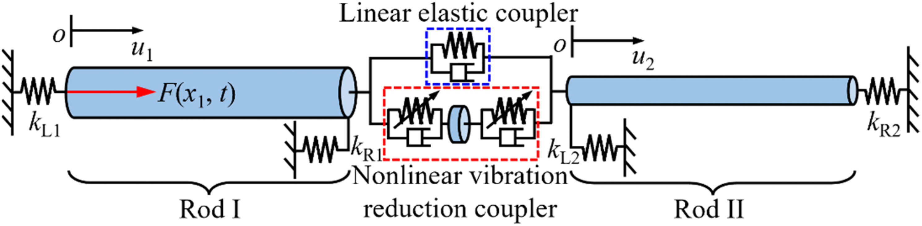


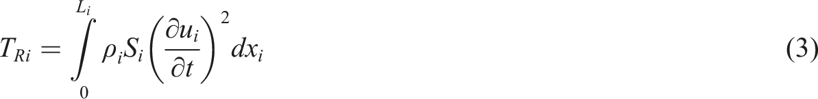
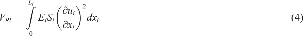
In this work, LM is applied to analyze the longitudinal vibrational responses of the rod system with an NVRC. Deriving the Lagrange term is the basement to predict longitudinal vibrational responses of the rod system, where the Lagrange term of the system consists of potential energy, kinetic energy, and external work. For each rod, its kinetic energy (TRi) and potential energy (VRi) can be derived as
Furthermore, the potential energy of the longitudinal boundary springs (VBi) is expressed as

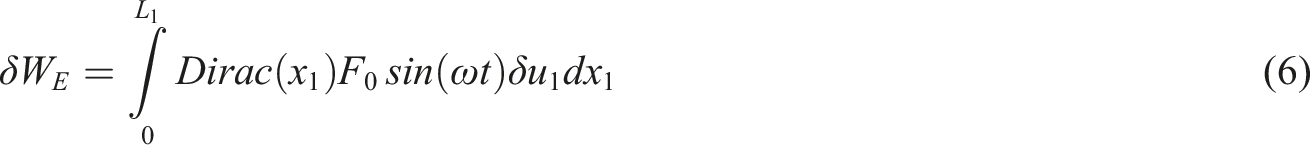
The virtual work done by the vibration excitation (WE) is derived as


For the elastic linear coupler, its potential energy (VC), and work done by the viscous damping force (WC) can be derived as


For the NVRC, its kinetic energy (TN), potential energy (VN), and the virtual work done by the viscous damping force (δWN) can be derived as


Based on the above derivations, the rod system’s total kinetic energy (TSystem), total potential energy (VSystem), and total virtual work done by the external force (δWSystem) can be derived as


The Lagrange term of the rod system with an NVRC can be derived as

Solution procedure
To simply establish the Lagrange term, the longitudinal vibrational displacements are rearranged as


To ensure the uniformity of the solution procedure,

By putting equations (18) and (19) and (24) into equation (17) and proceeding the subsequent step, namely
The Lagrange function of the rod system with an NVRC can be derived as
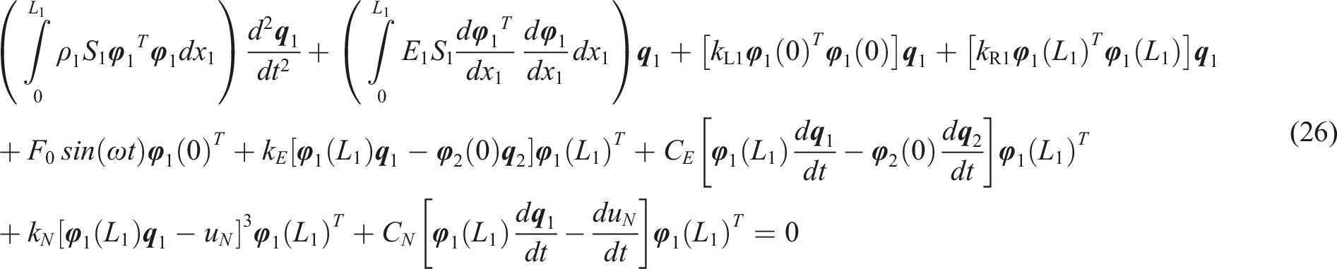
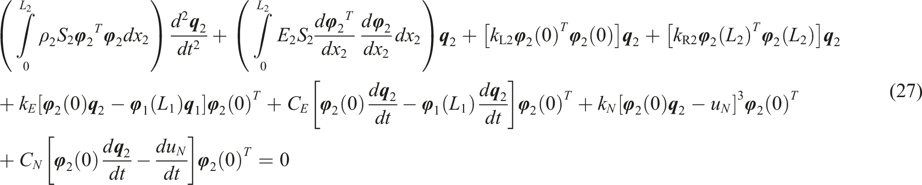

Longitudinal vibrational responses of the rod system with an NVRC can be gained by numerically solving equations (26) and (27).
Numerical analysis and discussion
In this work, longitudinal vibrational responses of the rod system with an NVRC are numerically solved by employing the MATLAB simulation platform. The parameters of the rod system are E i = 6.89 × 10¹⁰ Pa, ρ i = 2.8 × 10³ kg/m3, D1 = 0.06 m, D2 = 0.04 m, kLi = kRi = 5 × 10⁴ N/m, kE = 104 N/m, CE = 4 Ns/m, and F0 = 100 N. The observation points of the rod system are selected at x1 = L1 for Rod I and x2 = 0 for Rod II. Significantly, to guarantee the longitudinal vibration responses of the rod system remain stable, the time domain for calculating is set as 2000 periods of the vibration excitation, where the responses under the last 200 periods are regarded as stable results. Furthermore, in engineering practice, the vibration excitations act on the rod system mainly introduced by energy equipment, environment, and others. Their working frequency mainly stays in a low-frequency range. To make this work close to the engineering practice, this section mainly studies the longitudinal vibration responses of the rod system under a low-frequency range (1 Hz to 60 Hz). In addition, to make this work more easily understood by engineers, the numerical results are used as representative results in the subsequent study.
Verify the longitudinal vibration responses
To study the potential application of NVRC on vibration control of the rod system connected through a linear elastic coupler, ensuring the correctness of numerical results gained by LM is necessary. Thus, this section concentrates on the accuracy of the numerical results, where another prediction method is also employed to gain longitudinal vibration responses of the rod system with an NVRC, namely, the Galerkin truncation method (GTM). The parameters for the NVRC are mN = 0.2 kg, kN = 107 N/m3, and CN = 10 Ns/m.
Before studying the correctness of LM in calculating longitudinal vibration responses of the rod system with an NVRC, it is crucial to confirm its stability. Figure 2 gives the frequency responses of the rod system with an NVRC under different truncations. From Figure 2, it can be observed that frequency responses stabilize when the truncation number is 1-term, where 1-term truncation is chosen for the subsequent study. Frequency responses of the rod system with an NVRC under different truncations.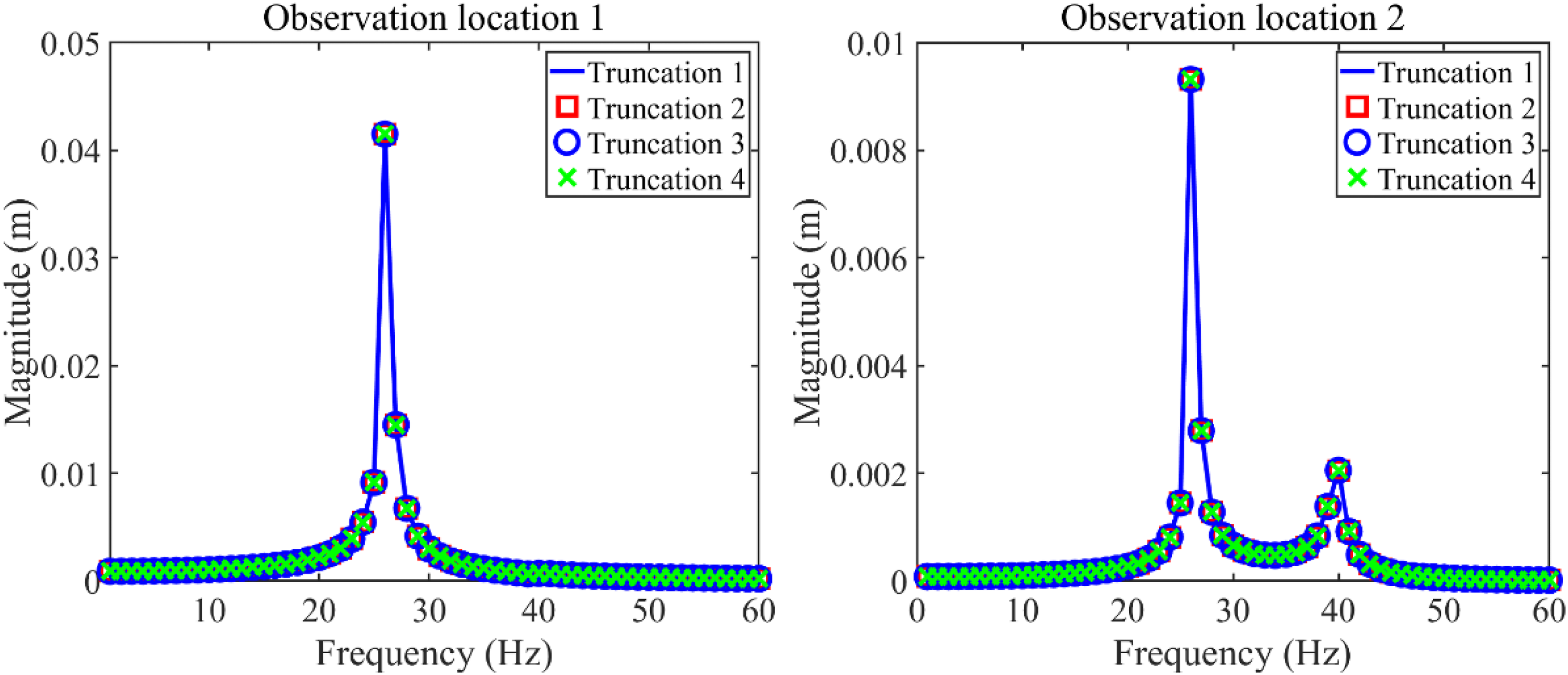
The reason for the longitudinal vibration responses of the rod system reaches stable when the truncation number is one is explained in the following. According to the modal analysis, the first four-order natural frequencies of the rod system can be obtained. For Rod I, the first four-order natural frequencies are 25.3 Hz, 4960.7 Hz, 9921.2 Hz, and 14,881.7 Hz. For Rod II, the first four-order natural frequencies are 37.9 Hz, 4960.8 Hz, 9921.3 Hz, and 14,881.8 Hz. Considering the frequency range studied in this work, only the 1st nature frequency of Rod I and Rod II is close to the aimed frequency range. Furthermore, the mode superposition method is used to expand the longitudinal vibration displacements, suggesting that the 1st made functions of Rod I and Rod II contribute greatly to the longitudinal vibration displacements. By the way, according to the modal analysis, Figure 3 gives the first four-order mode shapes of Rod I and Rod II, it can be seen from Figure 3 that the 1st mode shape of Rod I and Rod II presents a horizontal line, which means that the mode functions of Rod I and Rod II have the same value under different locations. Thus, the longitudinal vibration responses under observation points (x1 = L1 and x2 = 0) can be used to represent the whole vibration responses of Rod I and Rod II. The above analysis proves the reasonability of the observation points studied in this work. Mode shapes of Rod I and Rod II.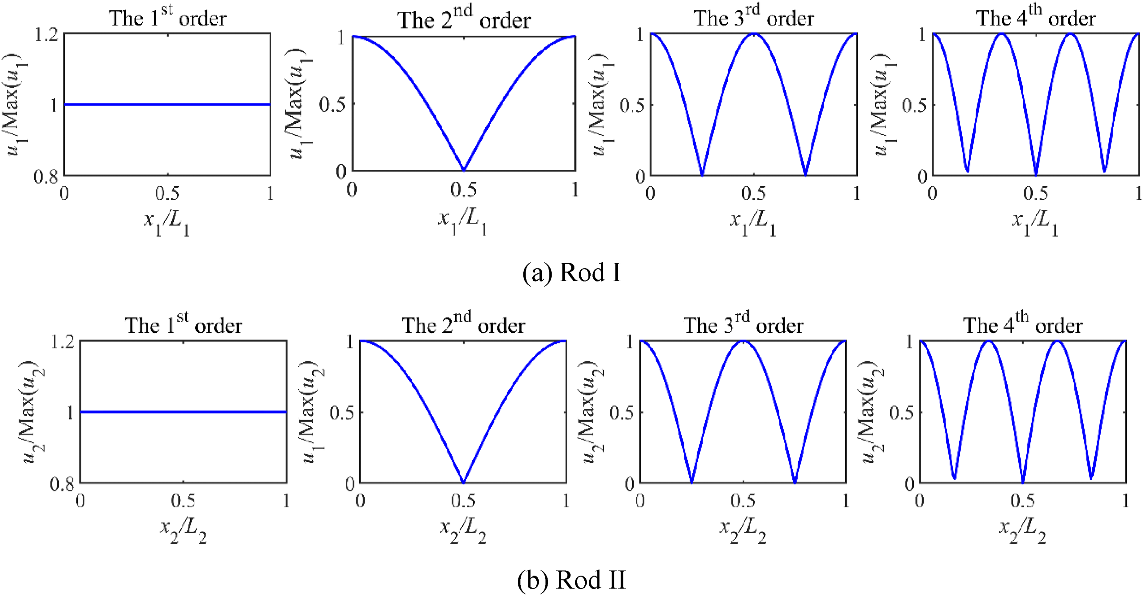
Subsequently, to evaluate the correctness of LM in calculating longitudinal vibration responses of the rod system with an NVRC, this work compares the frequency responses of the rod system with an NVRC calculated by LM against those obtained by using the GTM. The object of GTM is the vibration governing equation of the rod system with an NVRC, suggesting that the GTM and LM differ in their modeling approach. Figure 4 gives the frequency responses calculated from LM and GTM. From Figure 4, the close agreement among the responses from these methods as seen suggests that the computational outcomes from LM are reliable. Frequency responses of the rod system with an NVRC gained by LM and GTM.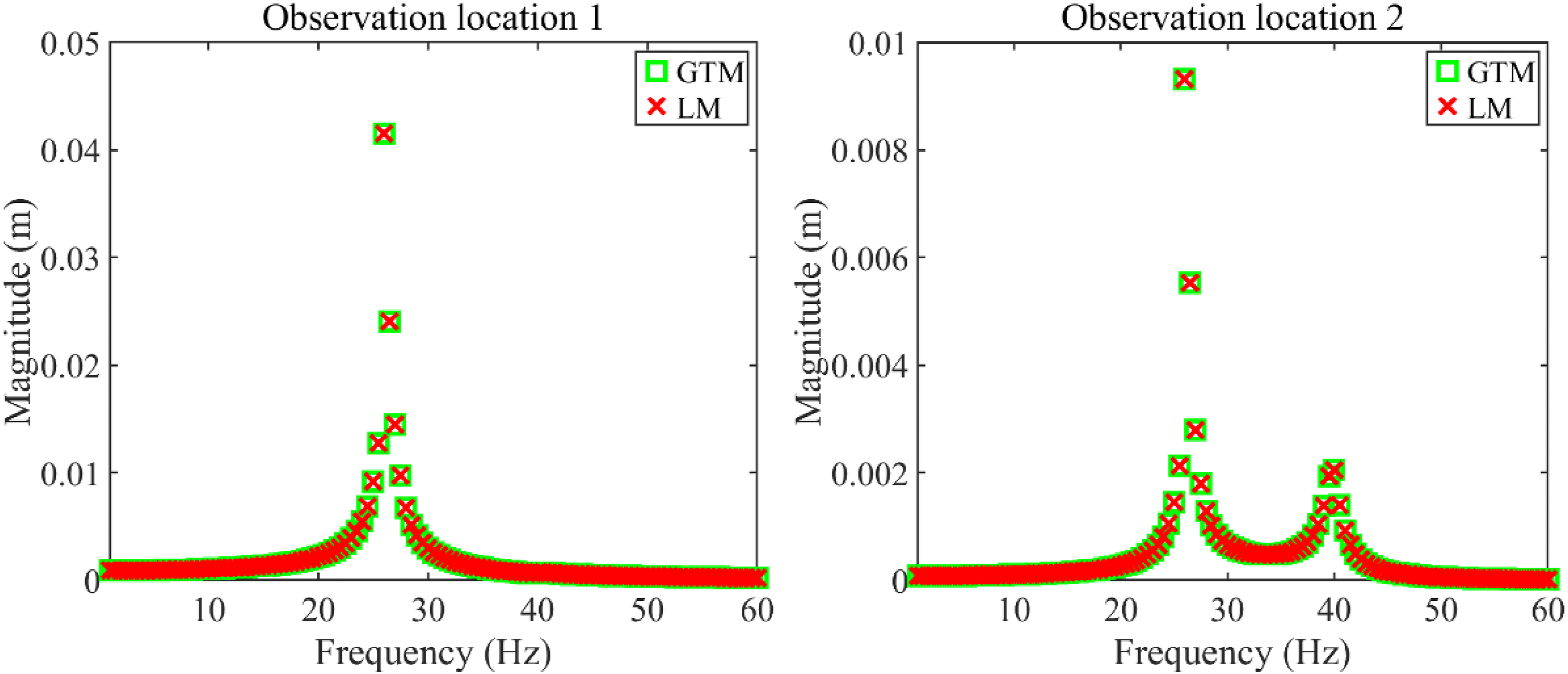
Longitudinal vibration reduction study of the rod system with an NVRC
This section investigates the potential application of NVRC on longitudinal vibration reduction of the rod system connected by a linear elastic coupler. In this section, the parameters of NVRC are selected as two combinations. For combination 1, the parameters of NVRC are kN = 107 N/m3, CN = 10 Ns/m, and mN = 0.1 kg. For combination 2, the parameters of NVRC are kN = 108 N/m3, CN = 6 Ns/m, and mN = 0.3 kg.
Figure 5 gives the frequency responses of the rod system with an NVRC under combination 1. From Figure 5, the existence of NVRC under combination 1 has a great influence on the frequency responses of the rod system. The introduction of NVRC can reduce the longitudinal vibration of the rod system effectively. It is worth mentioning that the vibration reduction is for each resonance area in frequency responses of both Rod I and Rod II. For Rod I, the vibration reduction ratio for the 1st resonance area is 46.8 %. For Rod II, the vibration reduction ratio for the 1st resonance area is 29.1 % while that for the 2nd resonance area is 59.4 %. Interestingly, no additional resonance region has been introduced into the frequency responses of the rod system by employing the NVRC, which suggests that the reasonable parameters of NVRC can reduce the vibration of rod systems without changing their vibration characteristics. Furthermore, it should be noted there are two resonance areas in the frequency responses of Rod II while there is only one resonance area in the frequency responses of Rod I. The reason for the above phenomenon is explained in the following. In this study, the vibration excitation acts on the left end of Rod I. According to the modal analysis of rods, the 1st resonance area corresponds to the 1st natural frequency of Rod I while the 2nd resonance area corresponds to the 1st natural frequency of Rod II. In the process of vibration transfer, the 1st resonance area of frequency responses is motivated when the vibration excitation’s frequency approaches the 1st natural frequency of Rod I. Then, the vibration is transferred to Rod II from the linear elastic coupler. When the vibration excitation’s frequency approaches the 1st natural frequency of Rod II, the vibration of Rod II is motivated, which corresponds to the 2nd resonance area of the rod system. Due to the vibration transfer direction being from Rod I to Rod II, the vibration of Rod I cannot be motivated in this situation. Thus, two resonance areas can be observed in the frequency responses of Rod II while there is only one resonance area appearing in the frequency responses of Rod I. Frequency responses of the rod system with an NVRC under combination 1.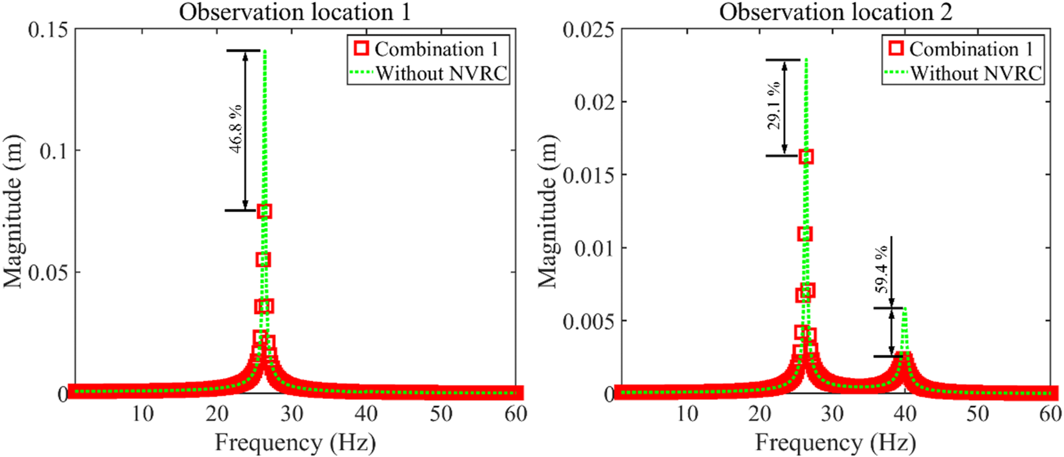
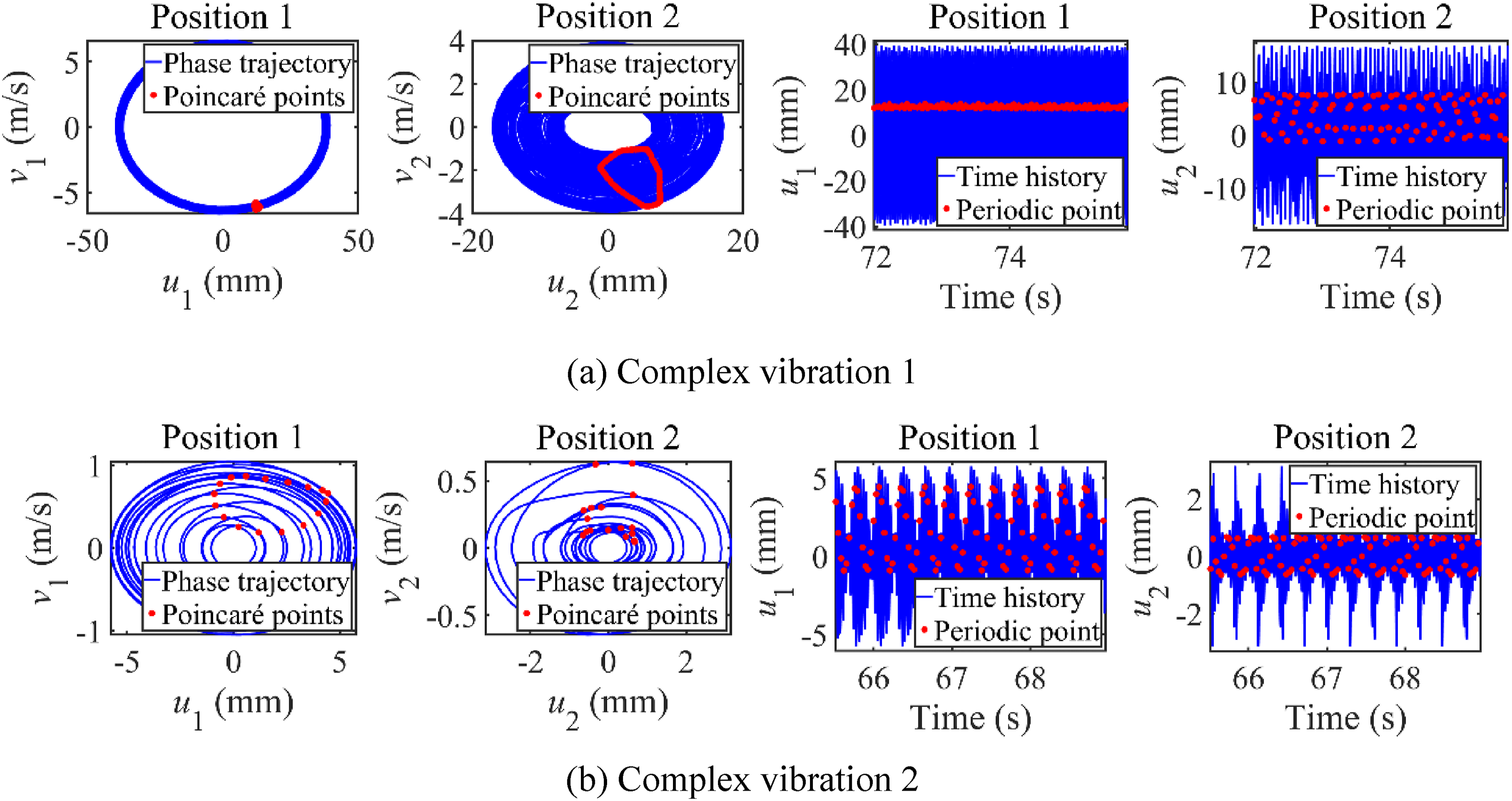
Figure 6 gives the frequency responses of the rod system with an NVRC under combination 2. From Figure 6, the existence of NVRC under combination 2 has a great influence on the frequency responses of the rod system. On one hand, the introduction of NVRC reduces the longitudinal vibration of the rod system. For Rod I, the vibration reduction ratio for the 1st resonance area is 71.0 %. For Rod II, the vibration reduction ratio for the 1st resonance area is 29.1 % while that for the 2nd resonance area is 56.6 %. Compared to the vibration reduction ratio under combination 1, the vibration reduction ratio of the 1st resonance area of Rod I under combination 2 is stronger than that under combination 1. On the other hand, the vibration characteristics of the rod system have been changed when the parameters of NVRC under combination 2. According to frequency responses, complex vibration that has multiple amplitudes appears around the 1st resonance area of the rod system. It can be inferred that the vibration states of the complex vibration must be different from the normal vibration. Thus, Figure 7 gives the phase and time diagrams of complex vibrations to judge the specific vibration state of complex vibrations, where Figure 7(a) corresponds to complex vibration 1 while Figure 7(b) corresponds to complex vibration 2. From Figure 7(a), it can be observed that Poincaré points form a closed curve. Meanwhile, phase trajectories and time waveforms remain stable. Thus, the vibration state of complex vibration 1 is the quasi-periodic state. From Figure 7(b), it can be observed that finite Poincaré points appear in phase trajectories. At the same time, phase trajectories and time waveforms remain stable. It can be concluded that complex vibration 2 is in the multiple-periodic state. Frequency responses of the rod system with an NVRC under combination 2. Phase and time diagrams of complex vibration.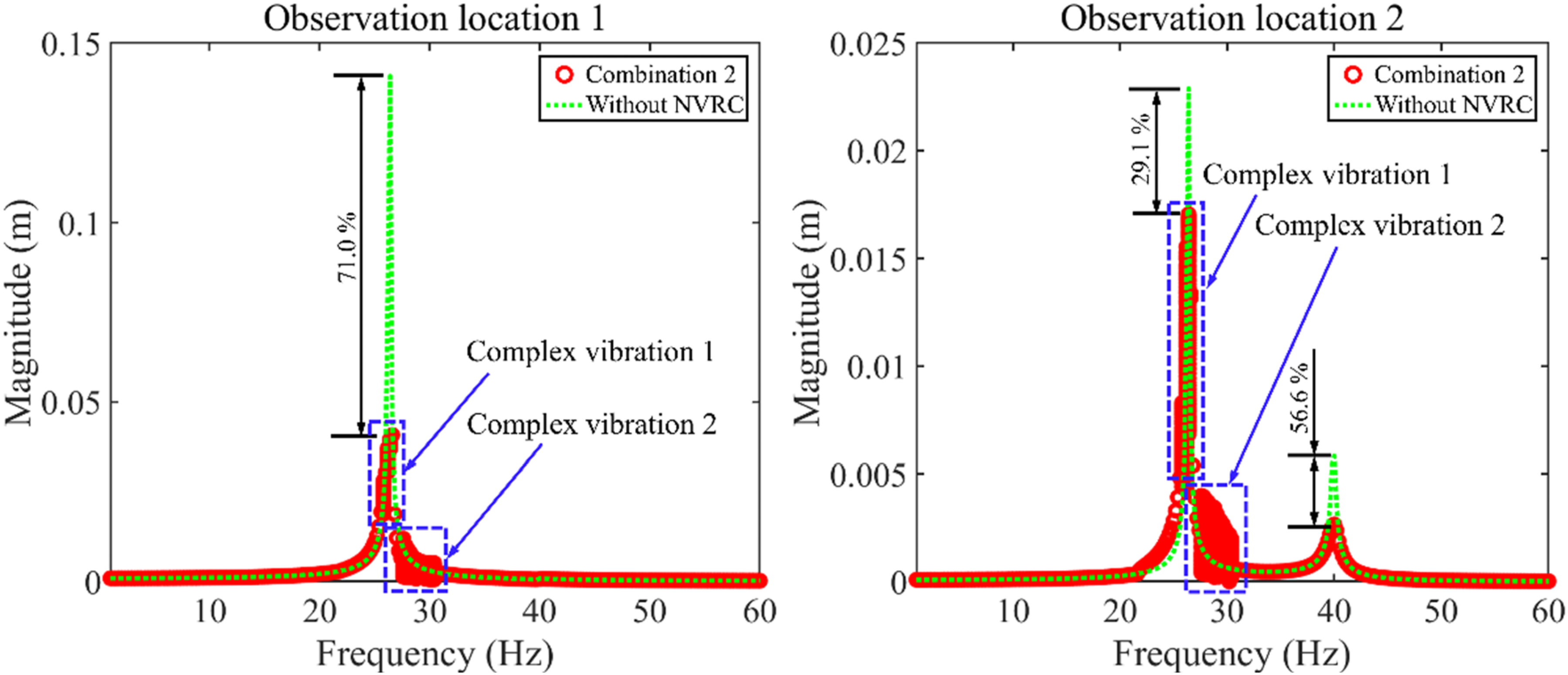
From the above analysis, the introduction of NVRC can reduce the vibration of each resonance area of the rod system at the same time. Under certain parameters, the vibration characteristics of the rod system are changed by employing NVRC. Importantly, to reasonably apply the NVRC for controlling the longitudinal vibration of the rod system, studying the effect of parameters belonging to NVRC on the vibration responses of the rod system is necessary.
The influence of NVRC’s parameters on frequency responses of the rod system
This section studies the effect of parameters belonging to NVRC on the longitudinal vibration responses of the rod system. Figure 8 gives the frequency responses of the rod system with an NVRC influenced by kN. In this numerical example, other parameters of the NVRC are CN = 10 Ns/m and mN = 0.2 kg. From Figure 8, the increase of kN has a great effect on the longitudinal frequency responses of the rod system with an NVRC. When kN increases to a certain value (4 × 10⁸ N/m3), the complex vibration appears in longitudinal frequency responses of the rod system. Before kN reaches the above value, increasing it is good for decreasing the peak value of the 1st resonance area of the rod system, which has a beneficial effect on the vibration reduction of the rod system. It is worth mentioning that the above strengthening vibration reduction is monotonous with the increase of kN. Furthermore, to judge the vibration state of complex vibration, subfigures are plotted in Figure 8, where Poincaré points are also graphed. From subfigures, Poincaré points compose a closed curve and phase trajectories remain stable. The vibration state of complex vibration is the quasi-periodic state. Frequency responses of the rod system with an NVRC influenced by kN.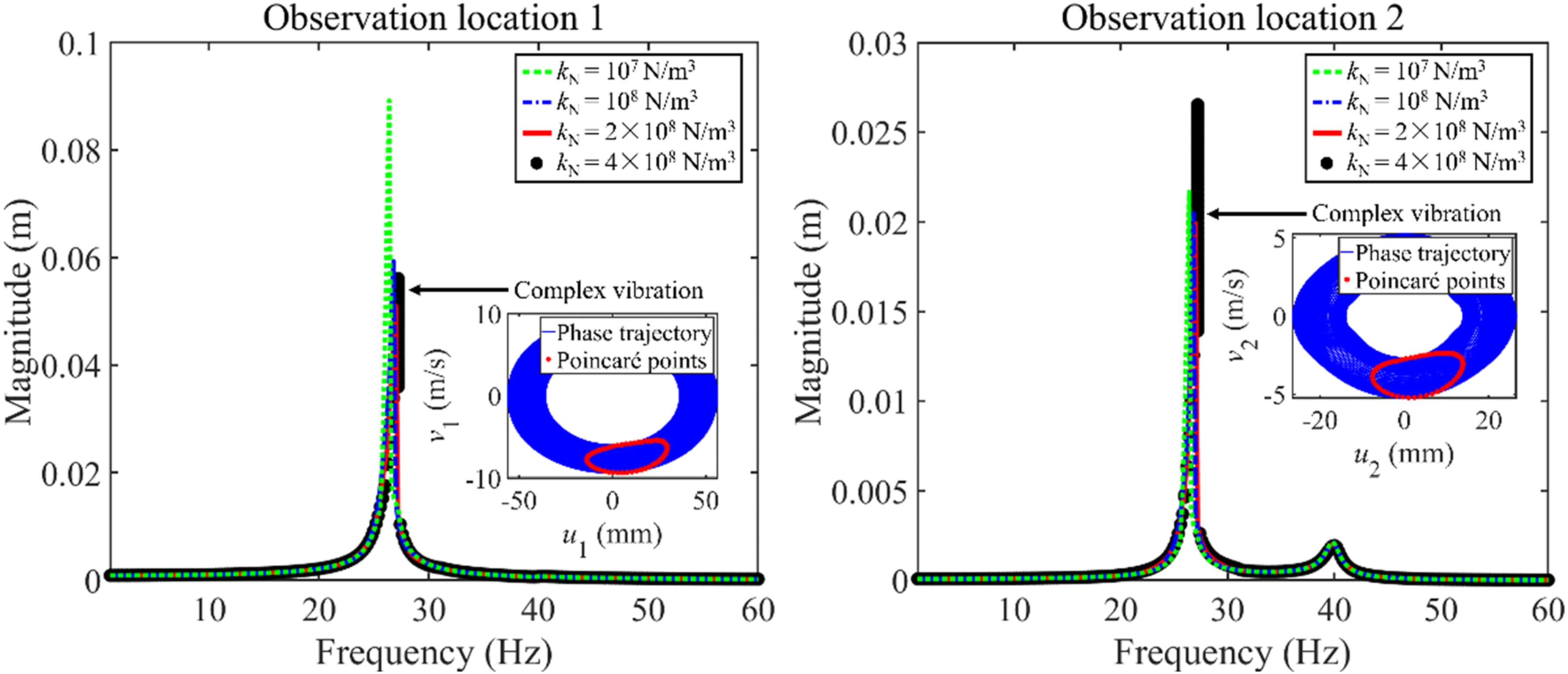
Figure 9 gives the frequency responses of the rod system with an NVRC influenced by mN. In this numerical example, other parameters of the NVRC are CN = 10 Ns/m and kN = 2 × 10⁸ N/m3. From Figure 9, the change of mN greatly influences the longitudinal frequency responses of the rod system with an NVRC. When mN changes to certain values (0.15 kg and 0.25 kg), complex vibrations appear in longitudinal frequency responses of the rod system. Furthermore, the increase of mN nonmonotonically influences the peak values of longitudinal frequency responses at the 1st resonance area. The above phenomenon indicates that it is unwise to control the vibration of the rod system by choosing mN as the adjustable parameter. Importantly, to judge the vibration state of complex vibrations, subfigures are plotted in Figure 9, where Poincaré points are also graphed. In each subfigure, Poincaré points compose a closed curve and phase trajectories remain stable. Thus, the vibration state of complex vibrations can be judged as the quasi-periodic. Frequency responses of the rod system with an NVRC influenced by mN.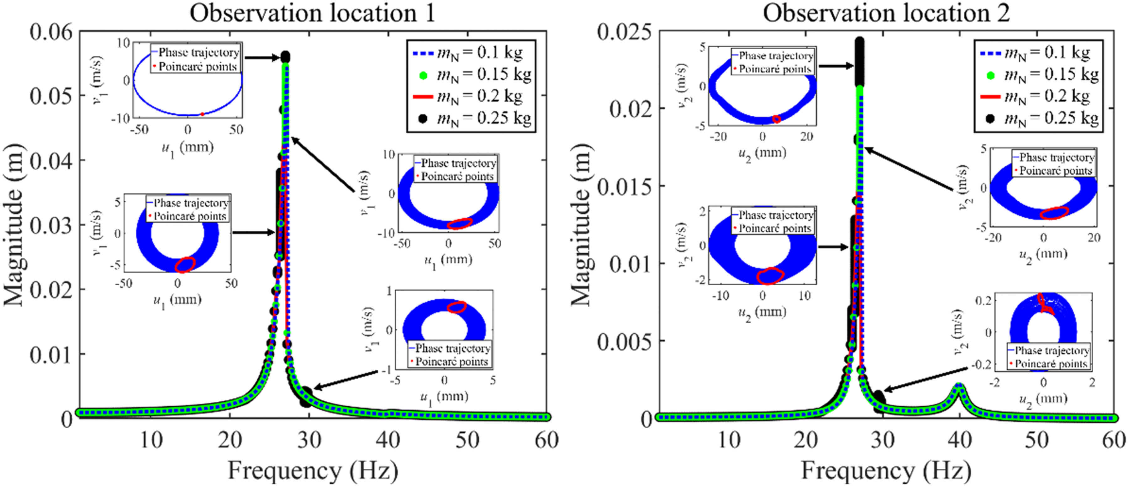
Figure 10 gives the frequency responses of the rod system with an NVRC influenced by CN. In this numerical example, other parameters of the NVRC are kN = 4 × 10⁸ N/m3 and mN = 0.2 kg. From Figure 10, the increase of CN has a great effect on the longitudinal frequency responses of the rod system with an NVRC. When CN stays at a low value (5 Ns/m and 10 Ns/m), complex vibrations show in longitudinal frequency responses of the rod system. The increase of CN is good for decreasing the peak value of the 1st resonance area of the rod system. Furthermore, the vibration reduction effectiveness monotonously increases with the increase of CN. Significantly, to judge the vibration state of complex vibration, subfigures combined with Poincaré points are plotted in Figure 10. For each subfigure, a closed curve is composed by Poincaré points while phase trajectories stay stable. The vibration state of complex vibrations is the quasi-periodic state. Frequency responses of the rod system with an NVRC influenced by CN.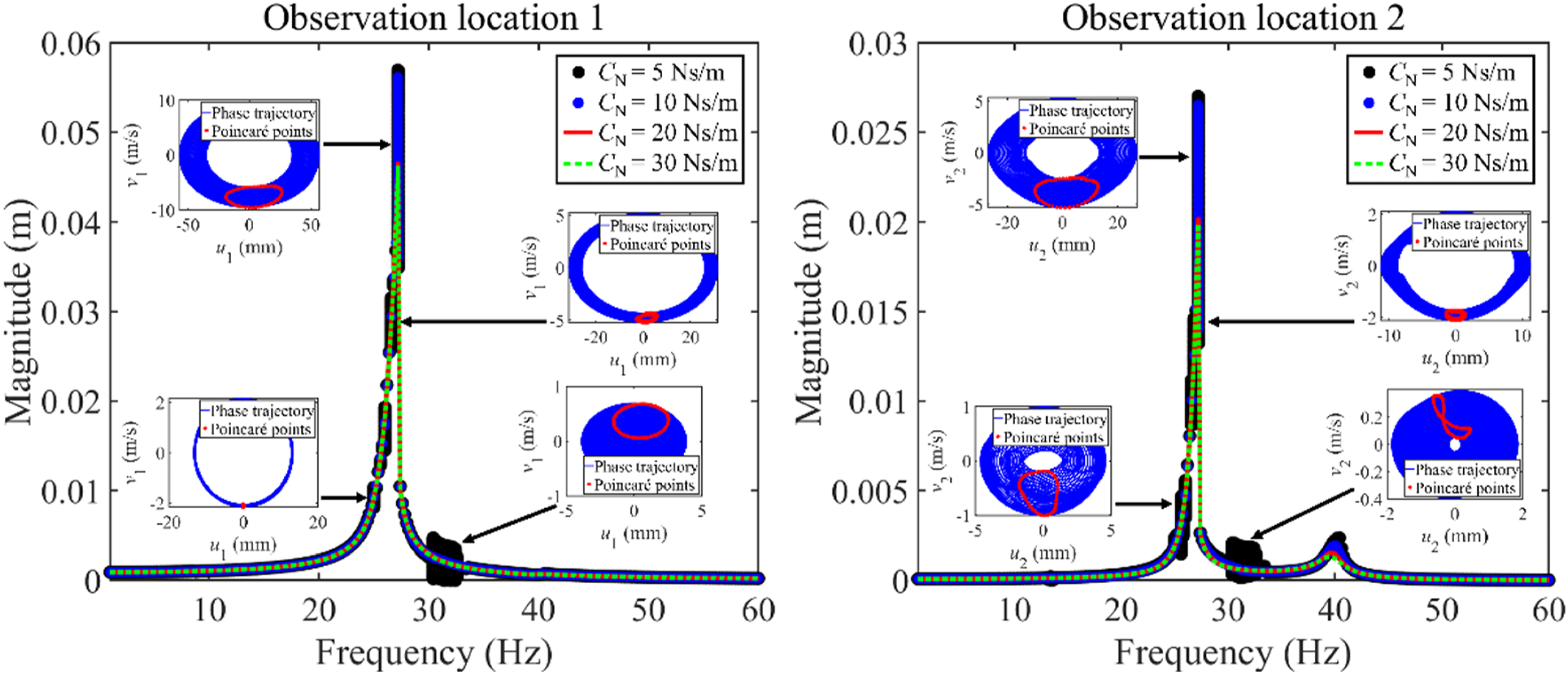
According to the influence characteristics of parameters belonging to NVRC on the longitudinal frequency responses of the rod system, kN and CN can be chosen as the adjustable parameters that strengthen the vibration reduction ratio of the rod system. Furthermore, it can be inferred that the longitudinal vibration of the rod system can be effectively controlled by choosing reasonable parameters of NVRC.
Conclusion
This work introduces an NVRC into a rod system connected through a linear elastic coupler, where the introduction of NVRC is aimed at controlling the longitudinal vibration of the rod system. The longitudinal vibration responses of the rod system with an NVRC are predicted by employing LM. In the numerical analysis, the correctness and stability of LM in calculating longitudinal vibration responses of the rod system with an NVRC are studied, where the chosen reasons for observation points are explained. Then, the longitudinal vibration reduction of the rod system by employing an NVRC is studied. Eventually, the effect of NVRC’s parameters on the frequency responses of the rod system is discussed. Some conclusions are made in the following.
Firstly, the LM can correctly calculate longitudinal vibration responses of the rod system with an NVRC.
Secondly, the introduction of NVRC can reduce the vibration of each resonance area of the rod system at the same time. Under certain parameters, the vibration characteristics of the rod system are changed by employing NVRC.
Thirdly, nonlinear stiffness and viscous damping of NVRC can be chosen as the adjustable parameters that strengthen the vibration reduction ratio of the rod system.
Overall, the longitudinal vibration of the rod system can be effectively controlled by choosing reasonable parameters of NVRC. The introduction of NVRC provides an effective way to control the longitudinal vibration of the coupling rod system.
Footnotes
Declaration of conflicting interests
The author(s) declared no potential conflicts of interest with respect to the research, authorship, and/or publication of this article.
Funding
The author(s) disclosed receipt of the following financial support for the research, authorship, and/or publication of this article: This work was supported by the Project of the Education Department of Guizhou Province; NO. [2021]315, National Natural Science Foundation of China; 52305249.
Data availability statement
The datasets generated during and/or analyzed during the current study are available from the corresponding author upon reasonable request.