
Abstract
The embedded track composite structure, composed of various polymer composites, is a specialized type of vibration- and noise-reducing track whose parameters and composition critically influence the vibration and impact dynamics experienced by trains. However, the complexity of the embedded track’s structural configurations and material properties presents significant challenges for its design, modeling, and analytical processes. To address these challenges, this study first designed the embedded track structure based on stress–strain criteria and subsequently analyzed the influence of individual components on system parameters. A simulation-based predictive model was then constructed and validated through both material and system-level testing, with results verifying the model’s accuracy. The calibrated model was then employed to predict the nonlinear vibration and impact behaviors of the embedded track composite structure. Key findings include: (1) the embedded track structure can be effectively divided into strain and compression strain zones, enhancing the system’s modal damping ratio; (2) preloading has a limited effect on the stiffness of the embedded composite track but shows a positive correlation with the fundamental frequency range of system damping, which can be represented using Rayleigh damping; (3) the high damping characteristics of the embedded track substantially attenuate high-frequency vibrations and wheel-rail impacts, particularly improving long-wavelength effects.
Keywords
Introduction
Low-carbon energy-saving and environmentally friendly rail transit is a major trend in the future development of transportation. 1 Embedded track is one of the green and environmentally friendly types of track. It is widely used in tram systems and has a complete system for track laying construction and operation maintenance (including rail grinding, rail welding, etc. 2 The embedded track composite structure, consisting of various polymer-based materials, serves as an advanced vibration- and noise-reduction solution for rail systems, where its design parameters are crucial to determining the vibration and impact characteristics affecting train performance. However, the complex structural configurations and material properties of embedded tracks introduce significant challenges to effective design, modeling, and analysis. Since the initial implementation of continuously supported embedded tracks in Deurne, Netherlands, in 1976, 3 substantial research has been devoted to exploring the vibration and noise reduction capabilities of such systems. The demonstrated effectiveness of embedded tracks in reducing vibration and noise has drawn considerable attention,4,5 resulting in extensive studies on the interaction between wheel-rail systems and the vibrational and acoustic behavior of embedded tracks.
Feng et al. 6 analyzed the dynamic stress distribution pattern of the embedded tram track substructure under train loads. Kang et al. 7 based on the specified track stiffness and the requirement of reducing the use of filling materials, the double-layer embedded track is designed by means of the response surface method and topology optimization. Shamalta et al. 8 pioneered one-dimensional and two-dimensional kinetic models to investigate the response of embedded tracks under moving load excitation. Building on these foundational models, Ling et al. 9 conducted approximate simulations using multi-rigid body dynamics, representing the embedded track fill materials with springs and dampers. Their comparative analysis of embedded and fastener tracks highlighted embedded tracks' advantages in terms of dynamic stability, smoothness, and passenger comfort, achieved through coded fasteners. However, due to the need for rail segmentation, this approach limits its effectiveness in studying high-frequency dynamics of embedded tracks.9,10 Han et al.11–13 studied the dynamics and vibration characteristics of subway train-embedded track system. The vibration and noise reduction performance of subway embedded track is also analyzed, 14 in which the length effect of track was also studied to improve the computational efficiency. In parallel, Sheng et al. 15 employed the theory of infinitely long periodic structures to model the dynamic properties of periodically and continuously supported tracks, demonstrating that dynamic behavior converges at 200 Hz, a frequency linked to track parameters, with European-style track fasteners exhibiting significant stiffness. While this finding aligns with other research,16,17 variations appear above 200 Hz, where periodic discrete supports introduce parametric excitation. 18 Despite their contributions, these models depend on stiffness damping to simulate the dynamic flexibility of continuously supported tracks, lacking consideration of the unique polymeric material properties in embedded tracks.
To address these gaps, Van Lier 19 applied the TWINS model alongside finite element methods to investigate the acoustic radiation characteristics of an embedded track, implementing optimization by shortening the rail and increasing the stiffness of the rail pad and surrounding elastic material. Comparisons between traditional and optimized embedded tracks with ballasted tracks indicated that the optimized embedded track achieved a 46 dB(A) reduction in noise compared to ballasted tracks. Similarly, Zhao et al. 10 employed site testing, 3D finite element, and boundary element methods to predict vibration and acoustic radiation from an embedded tram track, validating their model through simulation and empirical data. Their work further optimized the slot structure of the embedded track. However, simulations in this analysis were influenced by rail roughness spectra, impacting optimization outcomes, and while finite element modeling proved effective, the boundary element approach lacked similar validation. Building on these studies, Nilsson et al. 20 calculated acoustic radiation from embedded and traditional tracks using wavenumber-based finite element and boundary element methods. Results revealed that at specific frequencies, the free surface of the embedded track’s elastic material increased acoustic radiation efficiency for both the rail and elastic surface compared to traditional tracks. Nevertheless, the embedded track’s effective vibration attenuation offset the impact of this higher acoustic radiation efficiency, while at low frequencies, the dipole characteristics of the embedded track’s sound source contributed to higher noise emissions than conventional tracks. Kuchak et al.21,22 presents an efficient and cost-effective method for improving vibration dampers. Based on experimental and numerical modal analysis as well as Modal Assurance Criterion (MAC), this method employs finite element model updating techniques to develop a high-precision finite element model of the rail damper system within the studied frequency range.
Despite extensive research on embedded composite tracks, most studies have relied on linear theoretical models, often overlooking the intrinsic polymer characteristics and specific structural configurations of embedded tracks. To address these gaps, this study first designs the embedded track structure based on stress–strain conditions (Chapter 2), followed by an analysis of how different components influence system parameters. Material and system testing on small samples were then conducted to validate a simulation-based predictive model (Chapter 3), confirming its accuracy. Finally, the nonlinear vibration and impact characteristics of the embedded track were predicted (Chapters 4 and 5), providing insights into the embedded track’s performance under varied operational conditions.
System structure of embedded composite track
The composite structure of the embedded track serves as a unified system for reducing vibration and noise, utilizing various polymer-based composite materials. The strain states within the track’s cross-section vary significantly under loading conditions, a diverse selection of materials is employed to optimize the embedded track’s performance. This strain variation is critical, as the damping properties of these materials enhance system damping and stiffness exclusively in strained regions. Consequently, strategic material selection and precise distribution within the track structure enable targeted improvements in vibration attenuation and structural resilience.
Structure state
To assess the strain state induced by stress within the embedded track, a finite element model of the track, shown in Figure 1, was developed. Given that deformation is primarily concentrated within the structure in the groove, only the finite element model in the groove and connected parts of the slab are considered in this analysis. Both adopted PLANE 182 type (element behavior: plane strain), with fixed boundary constraints applied along the edges of the model. The model comprises a total of 1180 nodes and 1118 elements, as shown in Figure 15(a). To ensure a generalized approach, a unit vertical downward force is applied at the center of the railhead, and a single type of polymer material as the filling material is used throughout the groove. The selected material properties are an elastic modulus of 7.0 MPa, a Poisson’s ratio of 0.38, and a density of 1200 kg/m3. Local finite element model in groove of embedded track.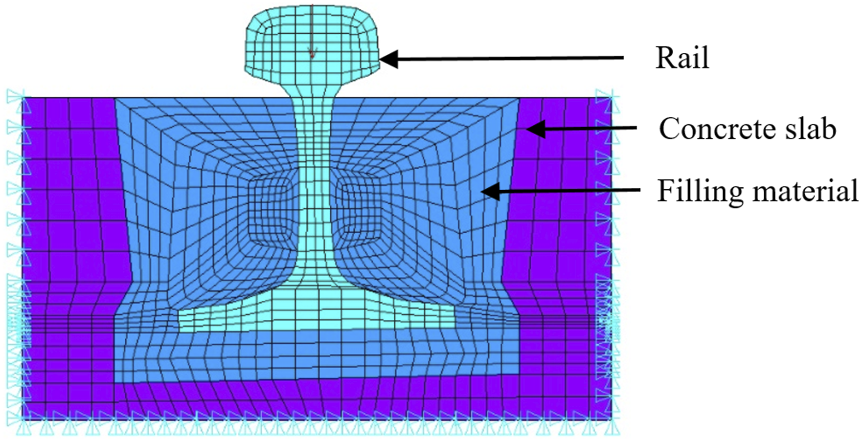
The strain distributions of the embedded track are shown in Figure 2. Figure 2(a) shows the compressive strain distribution, while Figure 2(b) shows the shear strain distribution. Contour plot for strains of the embedded track. (a) Compressive strain. (b) Shear strain.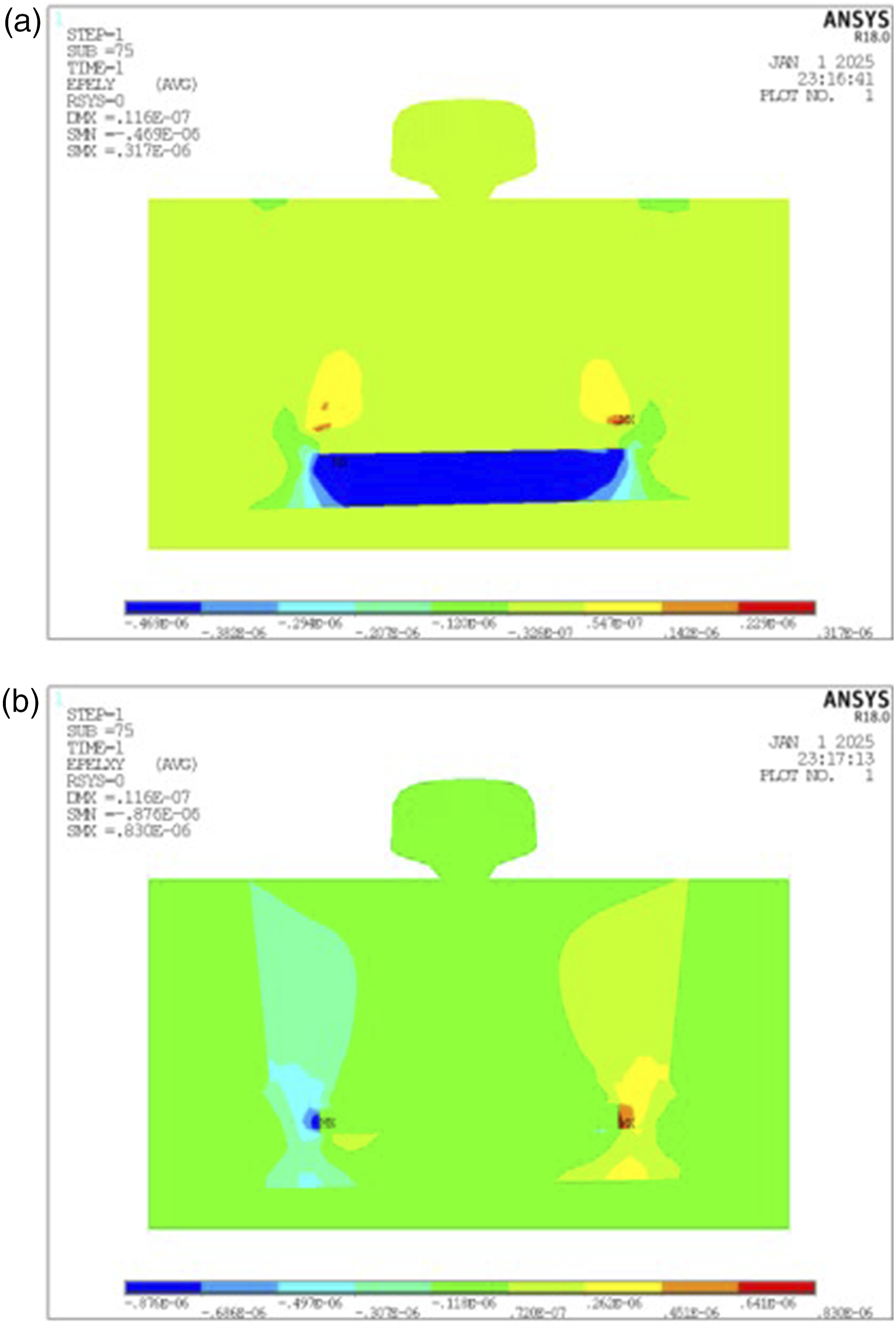
As illustrated in Figure 2, large compressive strain is primarily concentrated at the bottom under the rail, while large shear strain is predominantly located on both sides away from the rail. A non-strain area exists near the rail, allowing the embedded track structure to be divided into three distinct zones: the shear strain zone, the compressive strain zone, and the non-strain zone. Based on this classification, Figure 3 presents a new composite structure in the groove of embedded track. Composite structure in the groove of embedded track.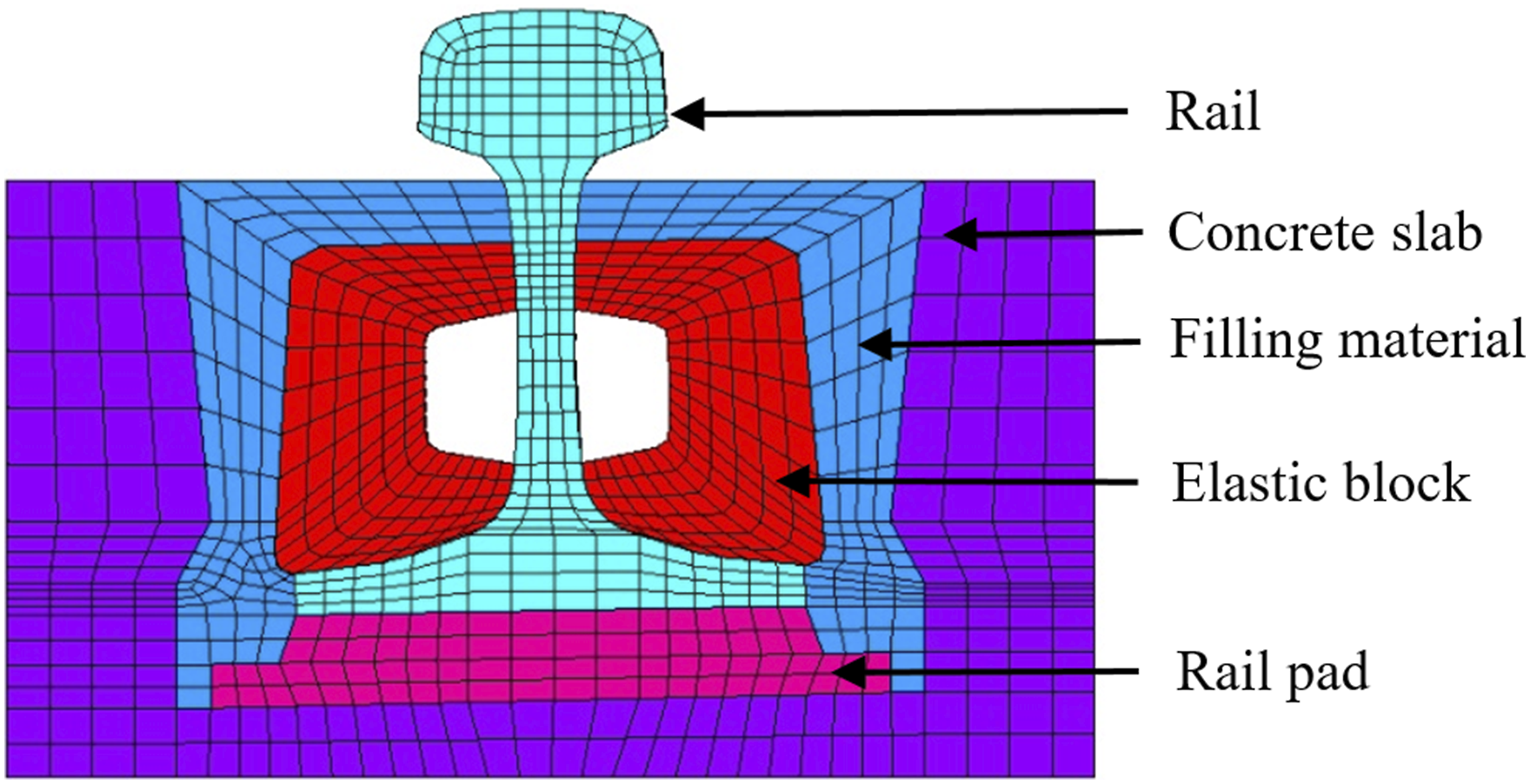
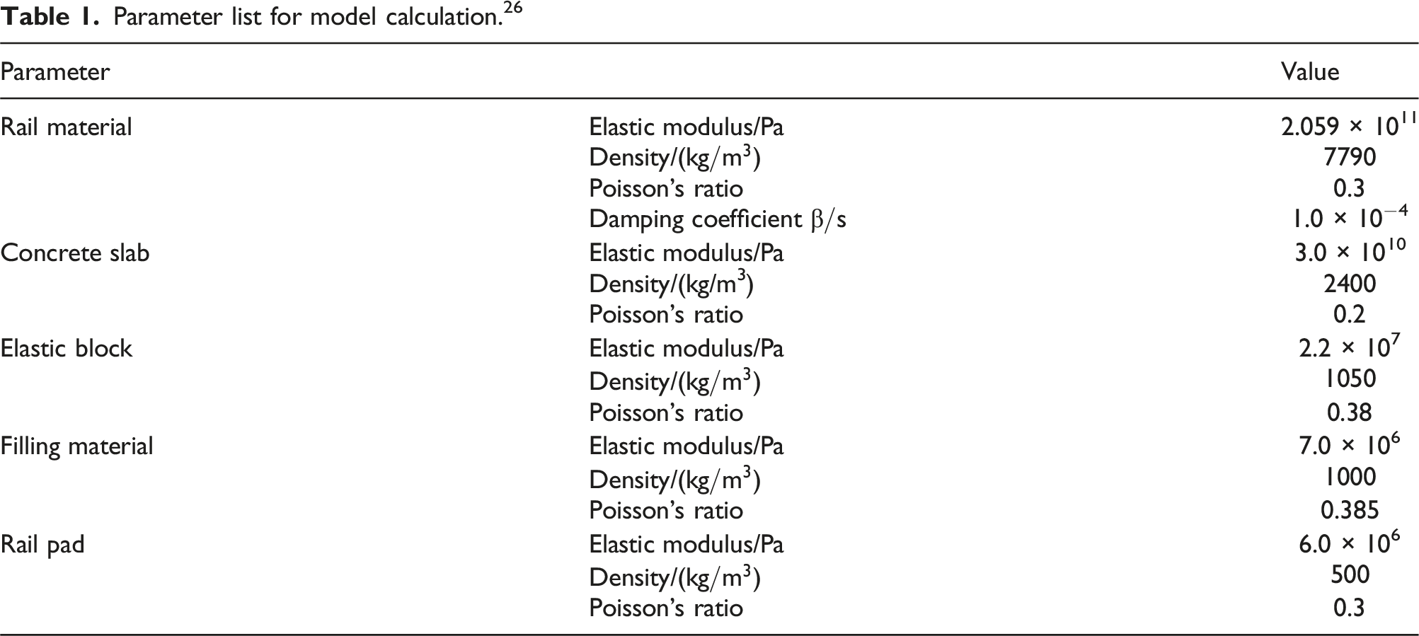
Parameter list for model calculation. 26
System damping and stiffness contribution
The stiffness of the track structure is a critical factor influencing the vibration of the track system. Given the strain variations observed at different locations within the embedded track, this section investigates the effect of the polymer’s elastic modulus on system stiffness, as illustrated in Figure 4. According to the standards outlined by the Ministry of Railways,
23
acceptable ranges for both vertical and horizontal stiffness values for railways are provided. Effect of polymer elastic modulus on system stiffness. (a) Effect of filling material on stiffness. (b) Sensitivity of filling material to stiffness. (c) Effect of elastic block on stiffness. (d) Sensitivity of elastic block to stiffness. (e) Effect of rail pad on stiffness. (f) Sensitivity of rail pad to stiffness.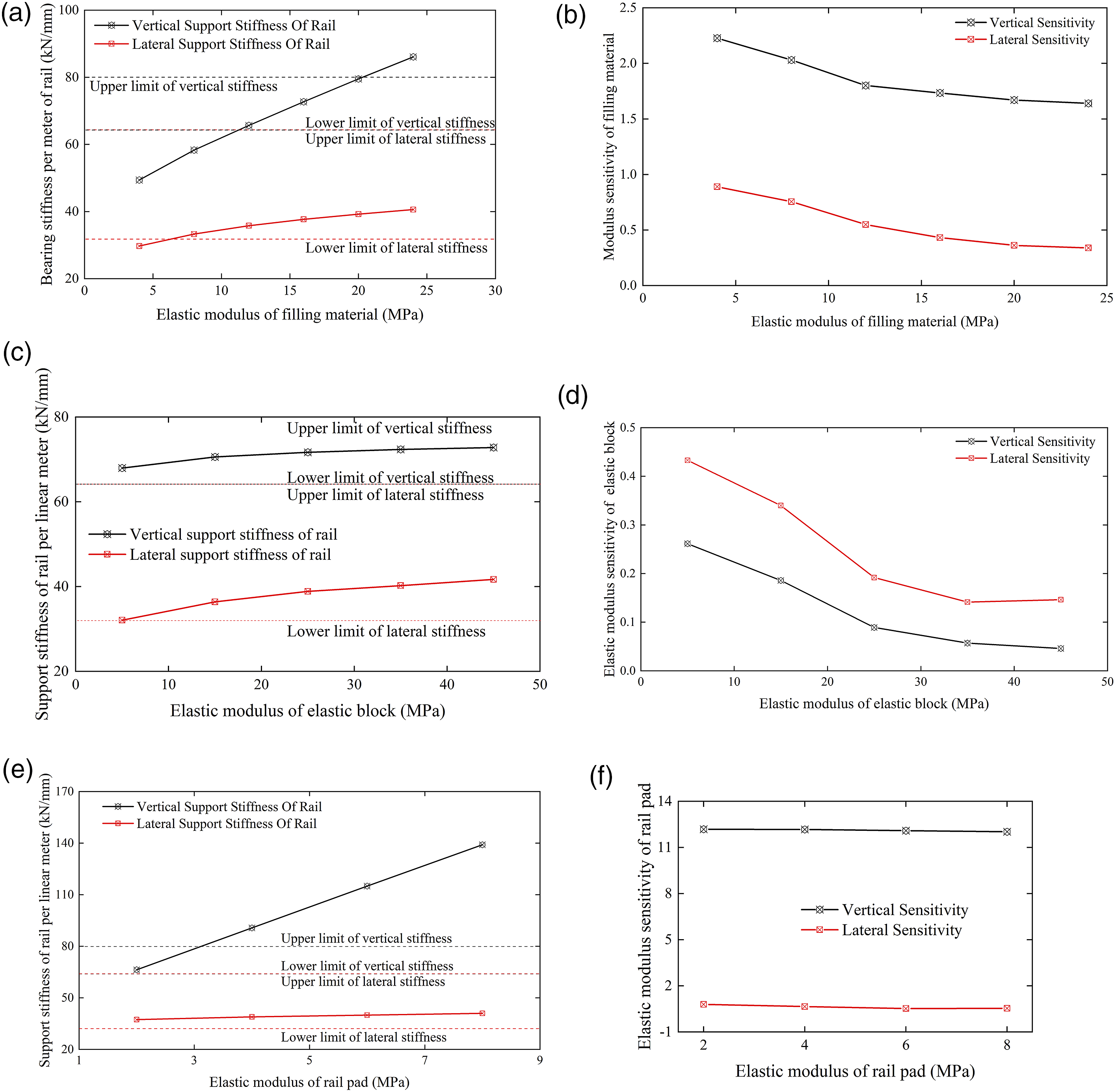
As shown in Figure 4, (1) the rail pad significantly effects the system’s vertical stiffness, while the elastic block and filling material have minimal effect on vertical stiffness; (2) conversely, the elastic block and filling material substantially effect the system’s horizontal stiffness, with the rail pad having negligible effect on horizontal stiffness.
This section also examines the effect of the loss factor of filling material on the system’s modal damping ratio, focusing on the first-order vertical motion of the rail. The results are presented in Figure 5. Effect of polymer loss factor on the system’s modal damping ratio. (a) Effect of material damping loss factor on modal damping. (b) Sensitivity of material damping.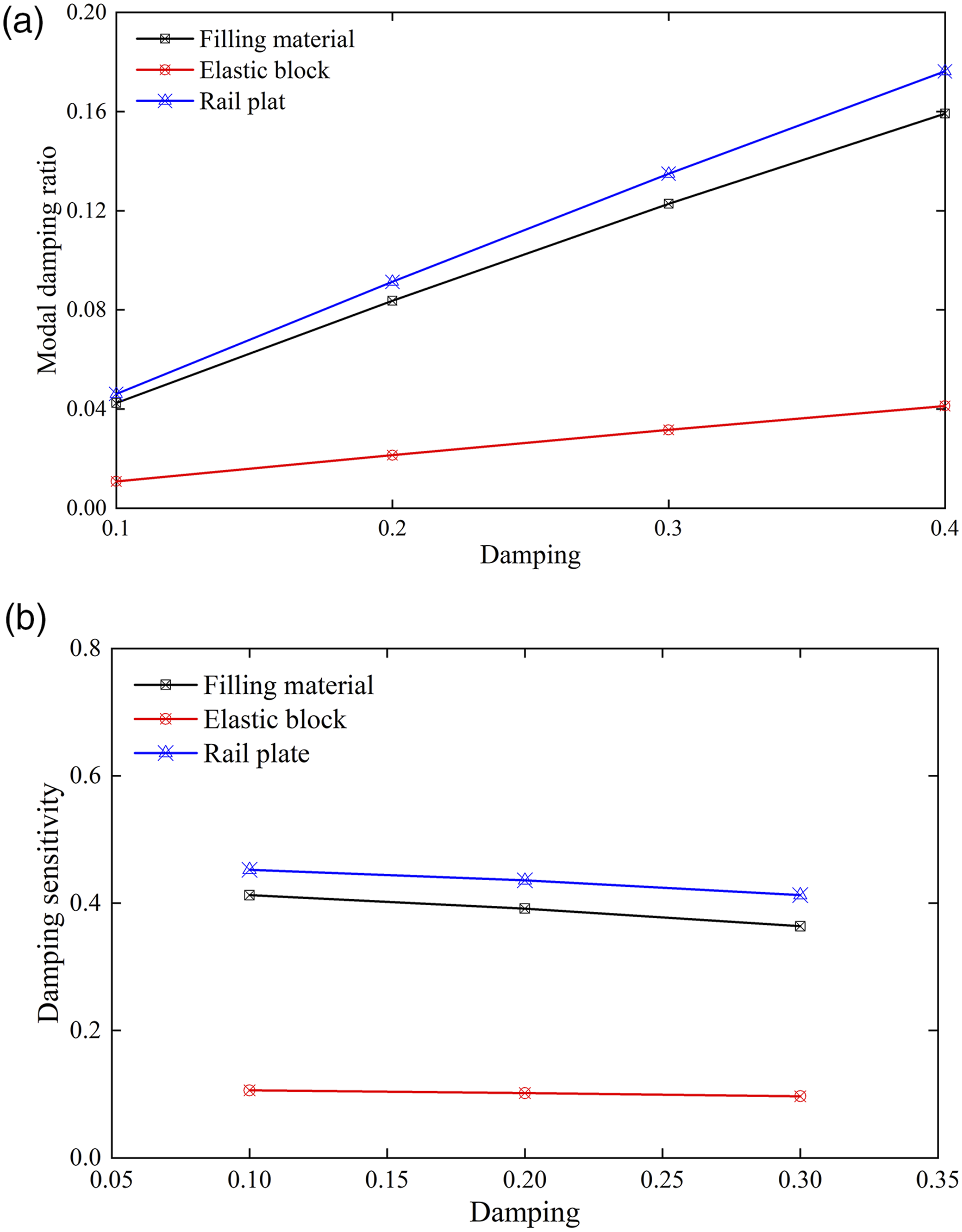
Figure 5 shows that the filling material and the loss factor of the rail pad significantly effect the embedded track’s modal damping ratio, whereas the elastic block has minimal impact on the system’s damping.
Experimental analysis and model validation
The polymer material properties of the embedded composite track are critical determinants of vibration and noise reduction performance. Among available options, Corkelast, a widely used polymer material produced by the Dutch company Edilon, comprises polyurethane and cork particles. 24 This material demonstrates high fluidity, transitioning to a solid phase at room temperature once poured into the groove. The embedded track system presents more complexity than conventional fastener-based tracks, both in terms of material composition (as it involves multiple polymer materials) and structural design. Unlike fastener tracks, which depend on elastic bars for fastening, the embedded track relies on a variety of polymer materials that interconnect to secure the track structure. This composite nature necessitates precise incorporation of measured data to accurately update the finite element model.
To achieve this, the following sections derive key material parameters by adjusting the polyurethane proportion and verified through system tests. First section details material testing to obtain predictive parameters. These parameters are then applied in second section to evaluate the low-frequency dynamic stiffness and dynamic damping of the embedded track structure, validating the model’s low-frequency. Due to current equipment limitations, high-frequency testing of the embedded composite track system was not feasible as outlined in second section. Therefore, third section employs hammer impact testing to validate the system’s high-frequency response.
Material testing of the embedded track composite structure
In this section, a TA Instruments Q800 Dynamic Thermomechanical Analyzer (DMA) was used to assess the storage modulus, energy dissipation modulus, and damping properties of the embedded track’s key components. The DMA experiment involved two main test categories: temperature ramping and frequency sweeping.
Temperature ramping applies an alternating force at a constant frequency within a specified temperature range, while the temperature increasing at a fixed rate. This approach generates curves, such as tanδ-T, to evaluate material damping properties or to establish a viscoelastic constitutive model for the materials. In contrast, frequency sweeping, varies the applied frequency within a set range at a constant temperature, allowing the relationship between material damping characteristics and loading frequency to be derived.
DMA experiments offer various loading modes, including tension, compression, and single cantilever, depending on the sample configuration and applied forces. In this study, the tensile loading mode was selected, with a sample width of 2 mm. For the temperature ramping test, a loading frequency of 10 Hz, a strain rate of 0.1%, and a temperature increase rate of 3°C/min were applied. The temperature range was set from −20°C to 60°C. The test results are presented in Figures 6–8. Storage modulus, loss modulus, and loss factor of elastic block.
25
(a) Storage modulus and loss modulus. (b) Loss factor Storage modulus, loss modulus, and loss factor of filling material.
25
(a) Storage modulus and loss modulus. (b) Loss factor. Storage modulus, loss modulus and loss factor of rail pad.
25
(a) Storage modulus and loss modulus. (b) Loss factor.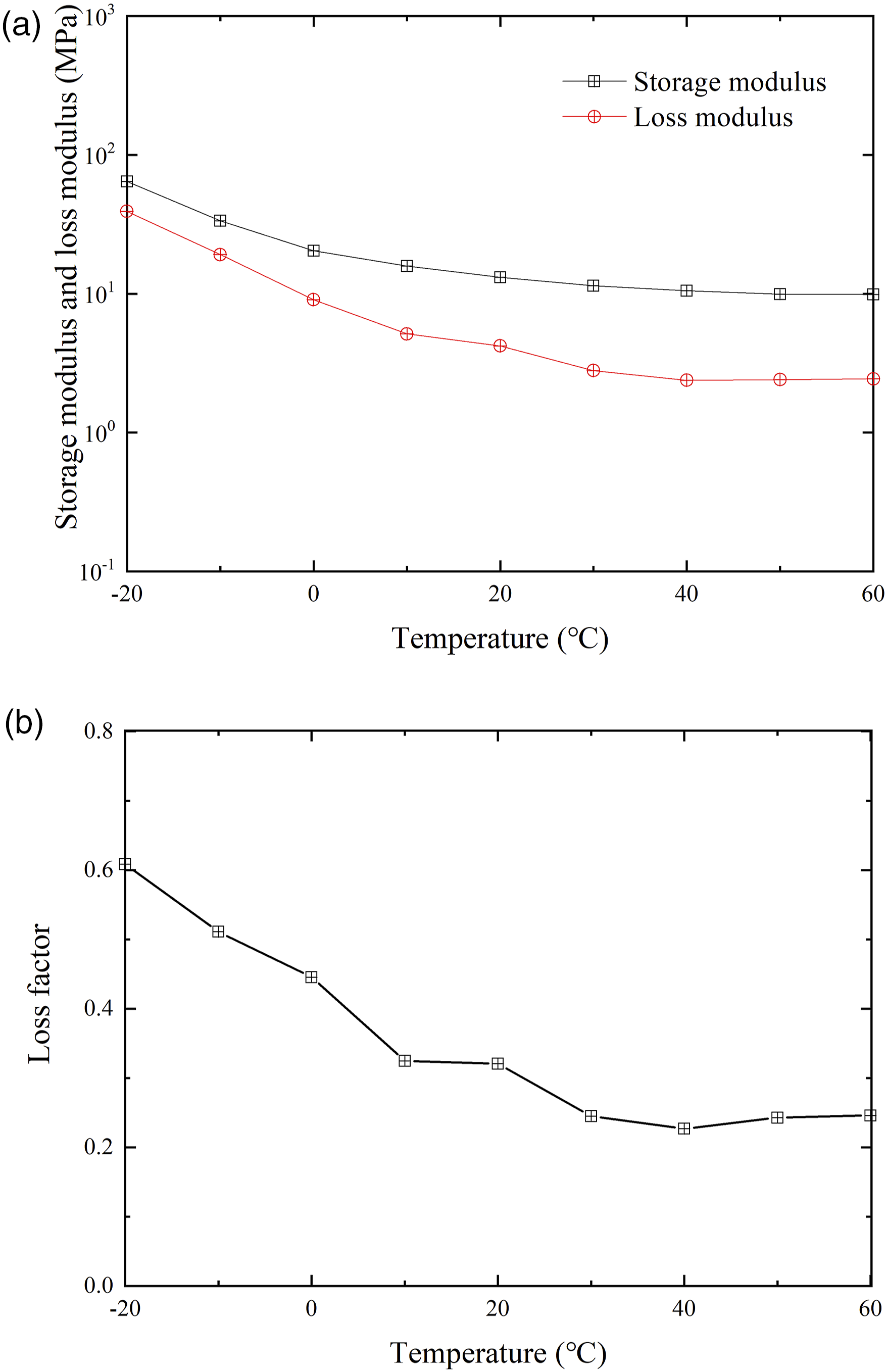
The following observations can be made from Figure 6: (1) Modulus changes with temperature: As the temperature decreases, both the storage modulus and the energy dissipation modulus increase. At a temperature of 60°C, the storage modulus is 9.9 MPa, and the energy dissipation modulus is 2.4 MPa. When the temperature drops to −20°C, these values rise to 64 MPa and 39 MPa, respectively. Notably, no vitrification transformation occurs in the elastic block within this temperature range. (2) Loss factor behavior: With decreasing temperature, the loss factor of the elastic block progressively increases. At −20°C, the loss factor reaches a maximum value of 0.60.
The following conclusions can be drawn from Figure 7: (1) Modulus changes with temperature: As the temperature increases, both the storage modulus and the energy dissipation modulus decrease. However, the storage modulus remains relatively stable across the temperature range, indicating that the filling material does not undergo vitrification transformation. (2) Loss factor behavior: With increasing temperature, the loss factor of the filling material gradually decreases. In the temperature range of 10°C to 60°C, the change in damping is minimal.
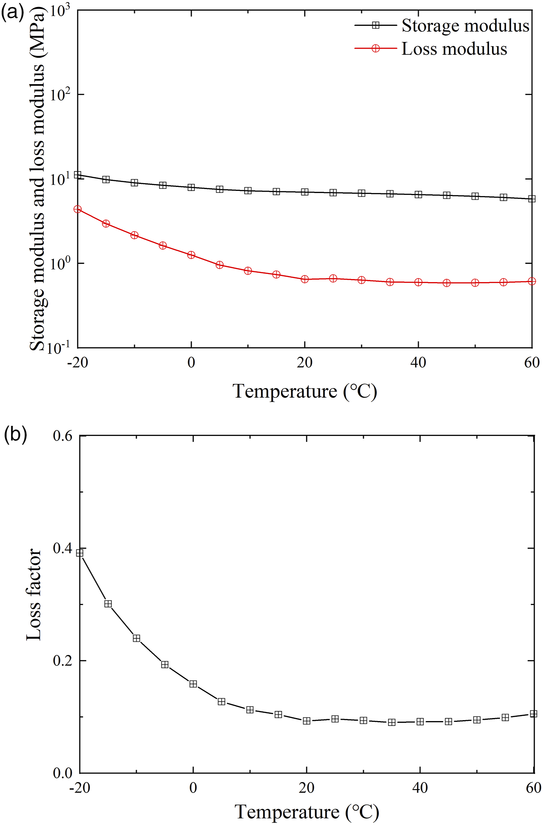
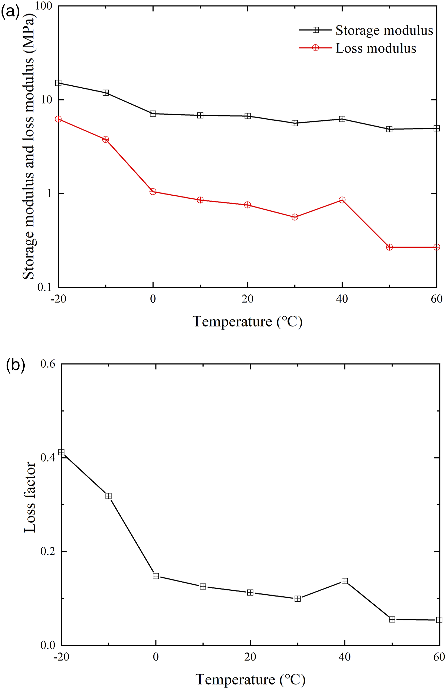
The following observations can be derived from Figure 8: (1) Modulus and loss factor response to temperature decrease: As the temperature decreases, the storage modulus, energy dissipation modulus, and loss factor all increase. Within the temperature range of −20°C to 60°C, the elastic modulus (storage modulus) varies between 15 MPa and 4.9 MPa. No vitrification transformation is observed in the soft pad material within this range. (2) Loss factor response to temperature increase: As the temperature increases, the loss factor of the filling material gradually decreases. At −20°C, the loss factor is 0.42, while at 60°C, it drops to 0.054.
Low-frequency dynamic stiffness and damping testing of the embedded track system
Based on the results from the polymer material tests, the parameters of the embedded track at an ambient temperature of 20°C are summarized in Table 1. At this temperature, the horizontal stiffness of the embedded track system is measured at 75 kN/mm, while the vertical stiffness is 30 kN/mm, both of which satisfy the stiffness requirements for railway systems.
Experimental objectives and equipment
The primary equipment and accessories used in this experiment include the stiffness testing system, embedded track short specimens, and a data acquisition system. Figure 9 illustrates the setup and loading method of the MTS system, along with the embedded track test specimens. The test specimens primarily consist of a 60 kg/m short rail, polymer material, rail pad, and a surrounding steel plate. The installation and loading means of the stiffness experiment for the embedded track. (a) The trial piece for the embedded track. (b) The experiment photo of the embedded track.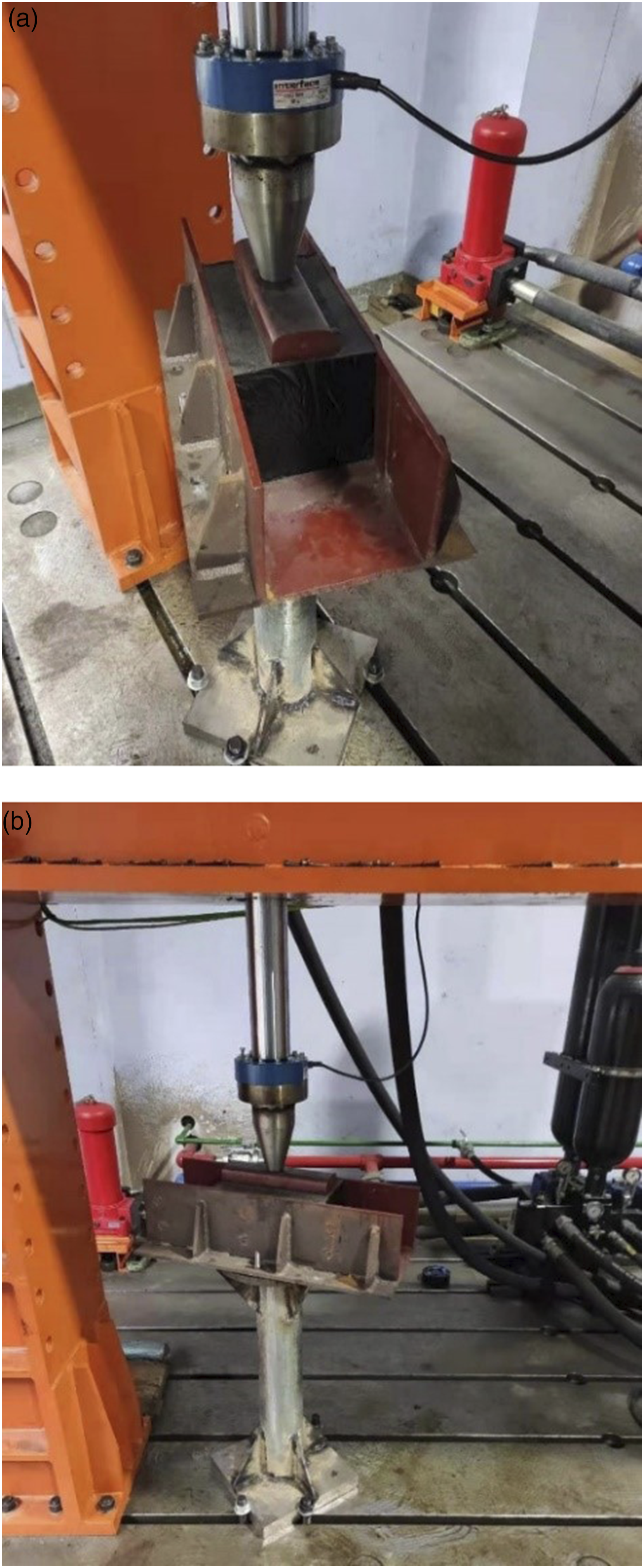
Experimental principle and operating conditions
The polymer material placed within the embedded track slot provides both elasticity and damping properties. Due to the material’s loosening process, its deformation inherently lags behind the applied excitation load Curve of load and displacement relationship for viscoelastic material. (a) Load-displacement time course curve. (b) Hysteresis loop.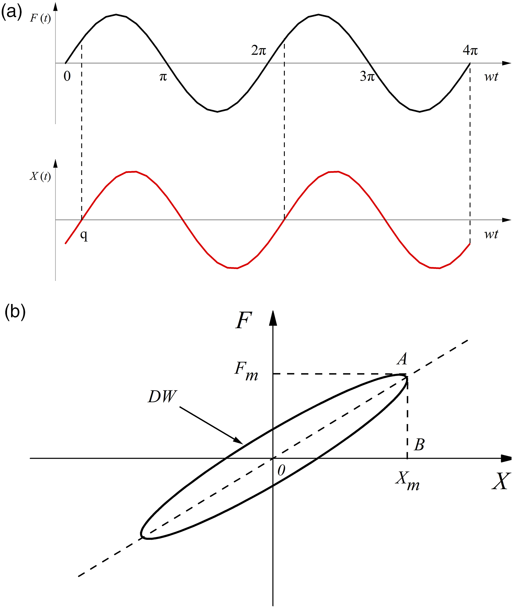
There is a certain phase angle
The elliptical area of the hysteresis loop denotes the kinetic energy △W consumed by the viscoelastic material within a time cycle of load displacement, the slope of the long axis of the ellipse represents the dynamic stiffness k of the viscoelastic structure; the flatness of the ellipse is proportional to the material equivalent viscous damping ratio ζ. The flatter the ellipse, the smaller the equivalent viscous damping ratio

where S△OAB denotes the area of triangle OAB (mm2); F m denotes the maximum load (kN); X m denotes maximum displacement (mm).
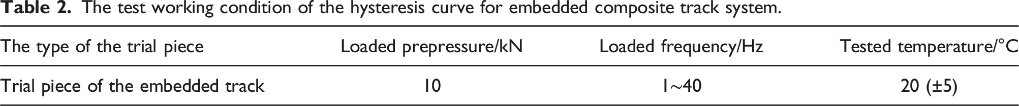
The test working condition of the hysteresis curve for embedded composite track system.
Test results and validation of the hysteresis curve for the embedded track system
The hysteresis curve test results for the embedded track system, obtained by using the MTS testing system, are presented in Figure 11. Experimental and simulation validation of the hysteresis curve. (a) 1 Hz. (b) 5 Hz. (c) 10 Hz. (d) 20 Hz. (e) 30 Hz. (f) 40 Hz.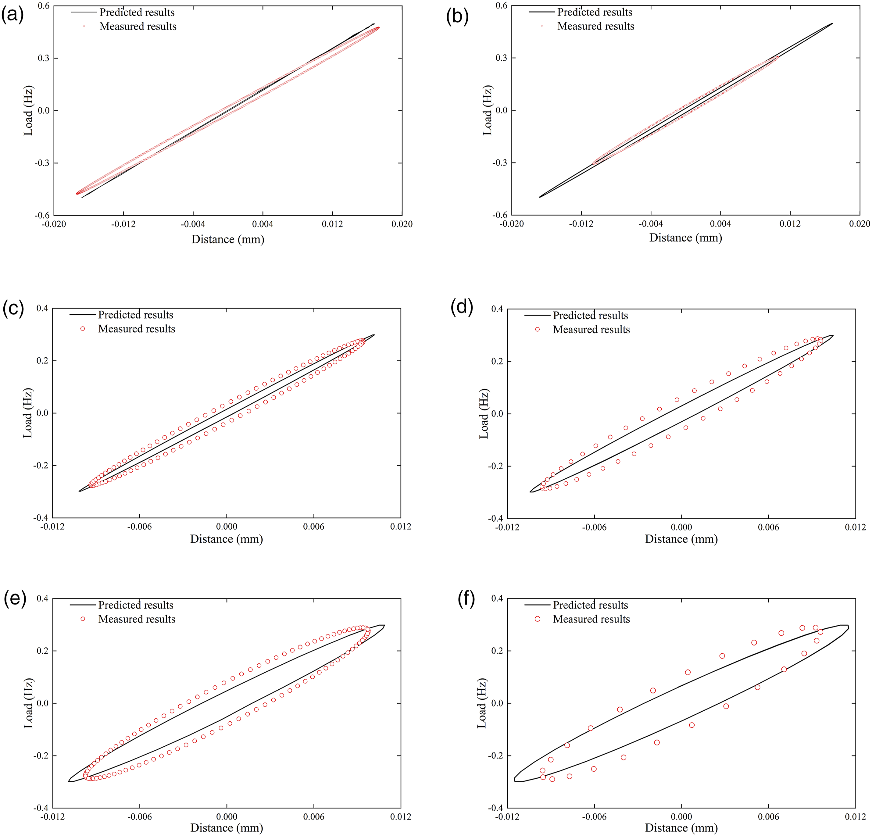
The following observations can be drawn from Figure 11: (1) The model developed in this study effectively simulates the stiffness and damping characteristics of the embedded composite track structure at a frequency of 40 Hz, with minimal discrepancy between the predicted and actual test results. (2) As the frequency increases, the semi-minor axis of the ellipse in the hysteresis curve expands, indicating that higher frequencies correspond to increased damping in the embedded composite track system.
To further explore the relationship between stiffness, damping, and varying frequencies in the embedded track, the slope and area of the hysteresis loop were analyzed. Figure 12 illustrates the relationship between the dynamic stiffness of the embedded track sample, the equivalent viscous damping ratio, and the applied loading frequencies. Low frequency dynamic stiffness and dynamic damping for the embedded composite track. (a) Dynamic stiffness. (b) Dynamic damping.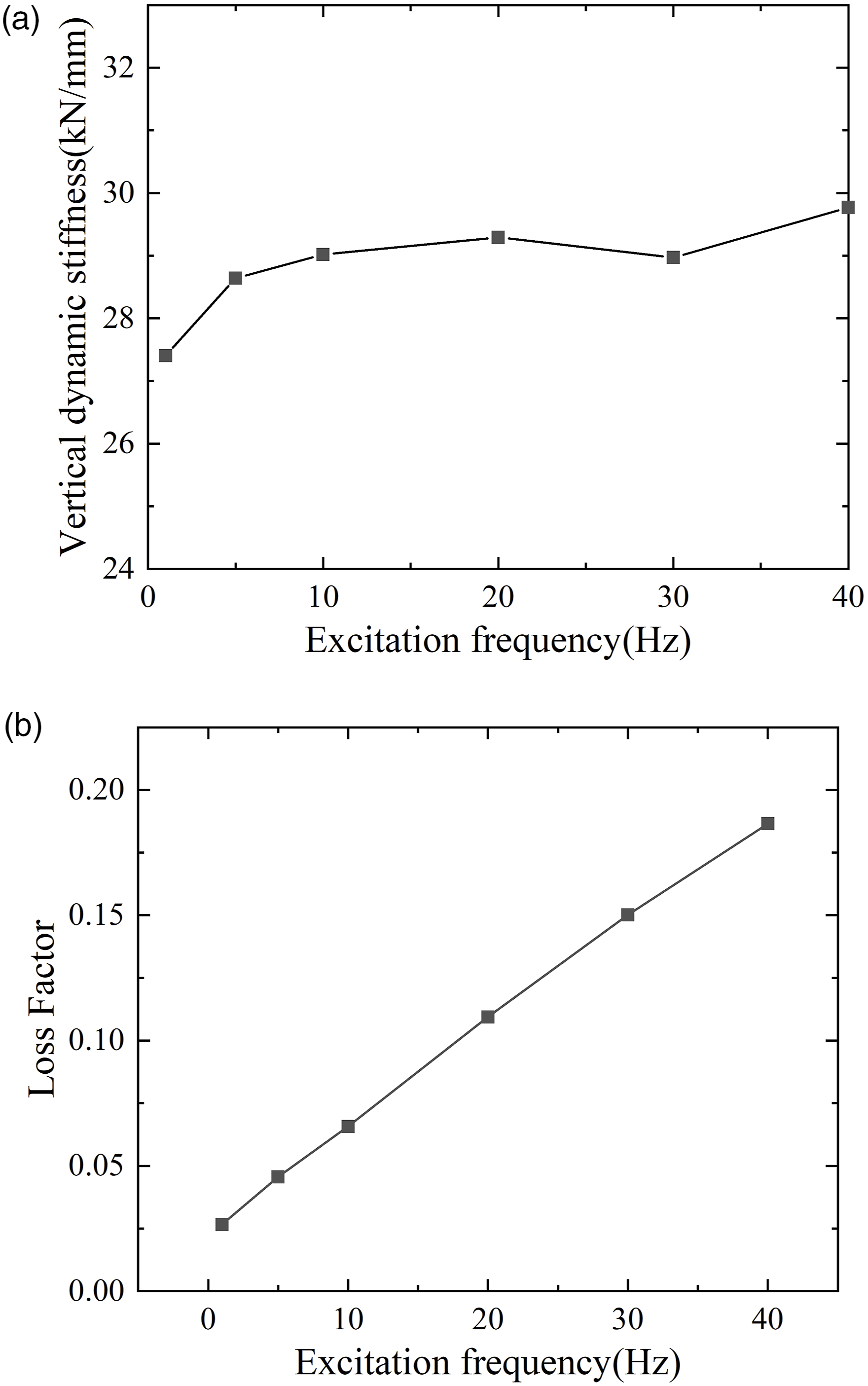
The following insights can be drawn from Figure 12: (1) Dynamic stiffness response to frequency: The dynamic stiffness of the embedded track structure shows an increases trend as the loading frequency rises. Before the loading frequency reaches 10 Hz, the dynamic stiffness increases rapidly; at frequencies below 10 Hz, the dynamic stiffness grows rapidly; however, when the frequency reaches or exceeds 10 Hz, this growth stabilizes, eventually approaching a constant value. This indicates that under high-frequency excitation, the variation in vertical stiffness of the embedded track specimen is minimal. (2) Equivalent damping ratio (ζ) response to frequency: The equivalent damping ratio ζ of the embedded track exhibits a linear increase with loading frequency, consistent with Rayleigh damping principles where damping is proportional to the stiffness matrix. At a loading frequency of 1 Hz, the equivalent viscous damping ratios under different prepressures are approximately 0.027. At 40 Hz, the equivalent viscous damping ratio reaches 0.186.
Frequency response testing and verification of the embedded track system
The frequency response test of the embedded track system was conducted in accordance with EN 15461, Railway Applications-Noise Emission-Characterization of The Dynamic Properties of Track Sections for Pass-By Noise Measurements. The primary objective of this test was to determine the intrinsic dynamic characteristics of the embedded track structure within a frequency range up to 1000 Hz. The hammer hitting method was employed to conduct the testing and analysis.
For on-site hitting the B&K8206 hammer was used, equipped with an aluminum head and capable of operating within an excitation frequency range of 0–4.5 kHz, with a force of 2200 N. A force transducer measured the excitation force. During the test, an accelerometer was mounted at the center of the rail head to measure vertical response. Hammer excitation was applied at the center of the track, with three strikes in the vertical direction to ensure consistent excitation. The setup for the on-site testing is shown in Figure 13. The on-site testing photos. (a) Front view. (b) Rear view.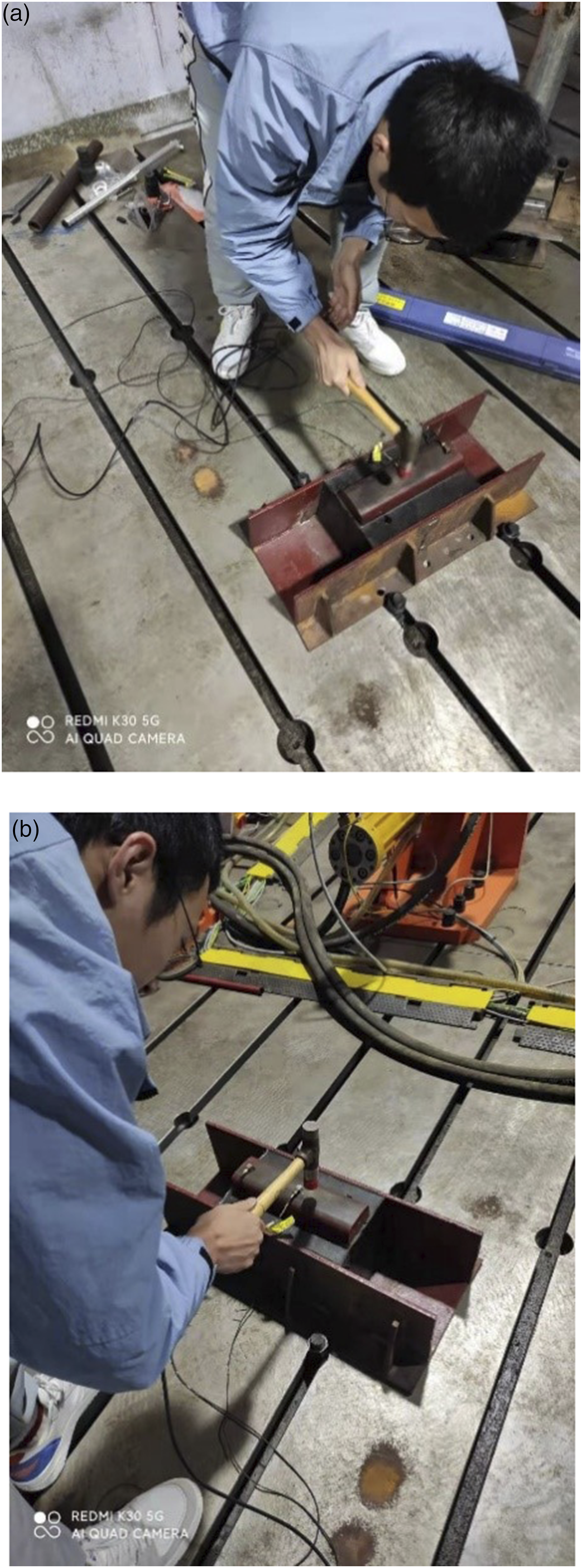
As shown in Figure 14, there is strong consistency between the measured results and the predicted results, indicating good alignment. However, the lower frequencies, the larger error margin is observed, likely due to reduced accuracy of low-frequency test results and the relatively short data collection duration of the hammer test, which introduces additional testing errors. Experimental and simulation validation of the embedded composite track structure. (a) Coherence. (b) Frequency response function comparison.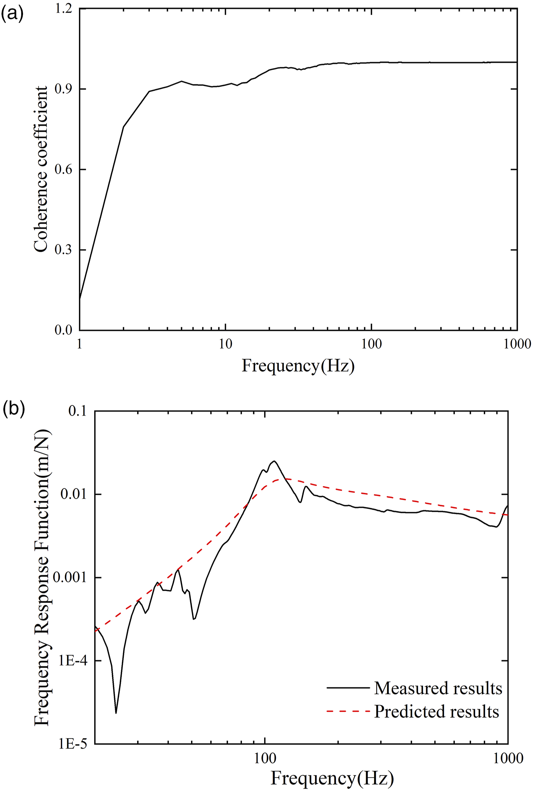
Non-linear vibration and impact model of the train-embedded track composite structure
Aim to investigate the non-linear vibration and impact behaviors of the train-embedded track composite structure, including the complex and non-linear characteristics of wheel-rail contact, a modeling approach based on relevant literature was adopted. Figure 15 presents a 3D transient finite element model of wheel-rail rolling contact, developed by using ANSYS-LS-DYNA. This model simulates the wheel-rail contact system operating on a specified railway line. Continuous solid element modeling was applied for the wheel and rail, and the wheel-to-rail contact was modeled using a “surface-to-surface” penalty-based contact algorithm. Finite element model of 3D transient wheel-rail contact. (a) Structure diagram. (b) Finite element model of WJ-8 fastener track. (c) Embedded track model.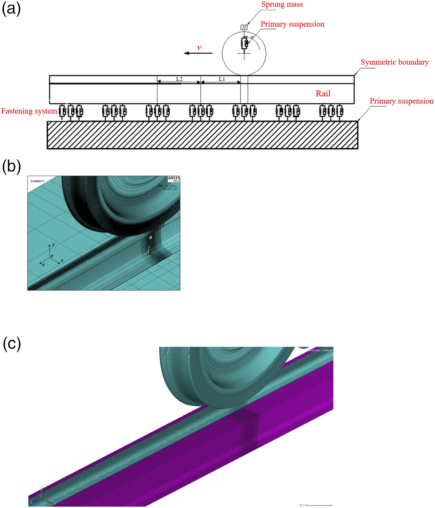
Since the high-frequency dynamic characteristics of the wheel-rail system are primarily effected by the elasticity of the wheelset and track, 18 the effects of the vehicle body and bogie frames on the calculation results are deemed negligible. Therefore, the components above the primary suspension were simplified as mass points connected to the wheels via primary suspension elements. Given the symmetry of the vehicle-track coupling system with respect to the vertical center plane, only half of the wheelsets and track are modeled, reducing the computational complexity.
To facilitate the description of the motion process, a structural diagram is established, as shown in Figure 15(a). The origin of the coordinate system is set at the center of the contact point at the initial rolling position of the wheel (point A). The region L1 represents the transition zone (three spans) and the region L2 represents solving zone (three spans). Based on the coordinate system of the constructed modeling according to Figure 15(b), the wheel rolls forward in the direction of the marked speed from its initial position. The x, y and z axes correspond to the lateral, vertical, and longitudinal directions, respectively.
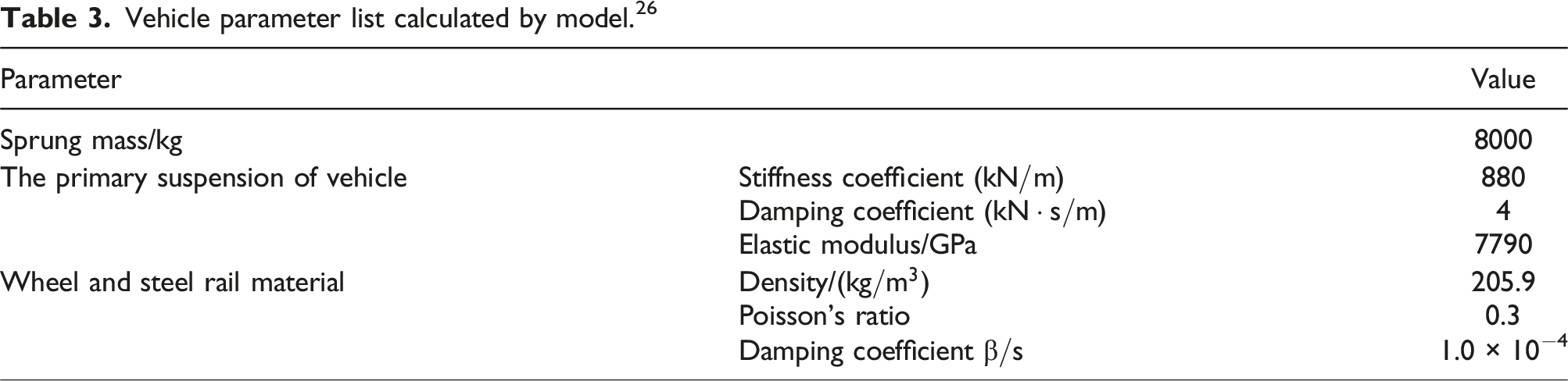
The wheel diameter analyzed by this paper is 920 mm, the profile of steel rail is CN60, rail bottom slope is 1:40, the track length of the model is 18.9 m, which covers multiple types of materials. Table 1 has enlisted the specific parameters required for modeling. In this paper, the wheels, steel rails, elastic block, filling material as well as rail pad all adopted SOLID 185 solid body (8 nodes hexahedral element), which are divided in grids unevenly. As shown in Figure 15(a), the grid size of the static solving zone (initial contact position) and dynamic solving zone (L2) is 1 mm (based on the experience). The grid size for the transition zone (L1) is a gradually changing grid with no more than 3 mm. For other solving areas, the largest feasible grid size is used to minimize the dimensions of the solution matrix. Following grid division, the surfaces of the wheel and steel rail remain smooth. The primary suspension is simulated by the distributed spring stiffness and damping unit to connect the vehicle mass and vehicle axle. Upon completing the grid division, the model comprises a total of 4,739,563 nodes and 4,289,851 elements.
Vehicle parameter list calculated by model. 26
Study on the vibration impact characteristics of the embedded track composite structure
To investigate the vibration impact characteristics of the embedded track composite structure, loading methods based on established literature. This study examines situation with welded connectors, using wavelengths of 0.05 m, 0.1 m, 0.5 m, and 1 m, with depth of 0.001 m, under a train operating speed of 400 km/h.
Wheel-rail impact force analysis of the embedded track
Figures 16(a), (c), (e), and (g) illustrate the wheel-rail impact force of the embedded track with a wave depth of 0.001 m, corresponding to welded connectors at wavelengths of 0.05 m, 0.1 m, 0.5 m, and 1 m, respectively. The associated frequency spectra of the wheel-rail impact force are shown in Figures 16(b), (d), (f) and (h). Vertical wheel-rail force in time and frequency domains. (a) Time domain (wavelength 0.05 m). (b) Frequency domain (wavelength 0.05 m). (c) Time domain (wavelength 0.1 m). (d) Frequency domain (wavelength 0.1 m). (e) Time domain (wavelength 0.5 m). (f) Frequency domain (wavelength 0.5 m). (g) Time domain (wavelength 1.0 m). (h) Frequency domain (wavelength 1.0 m).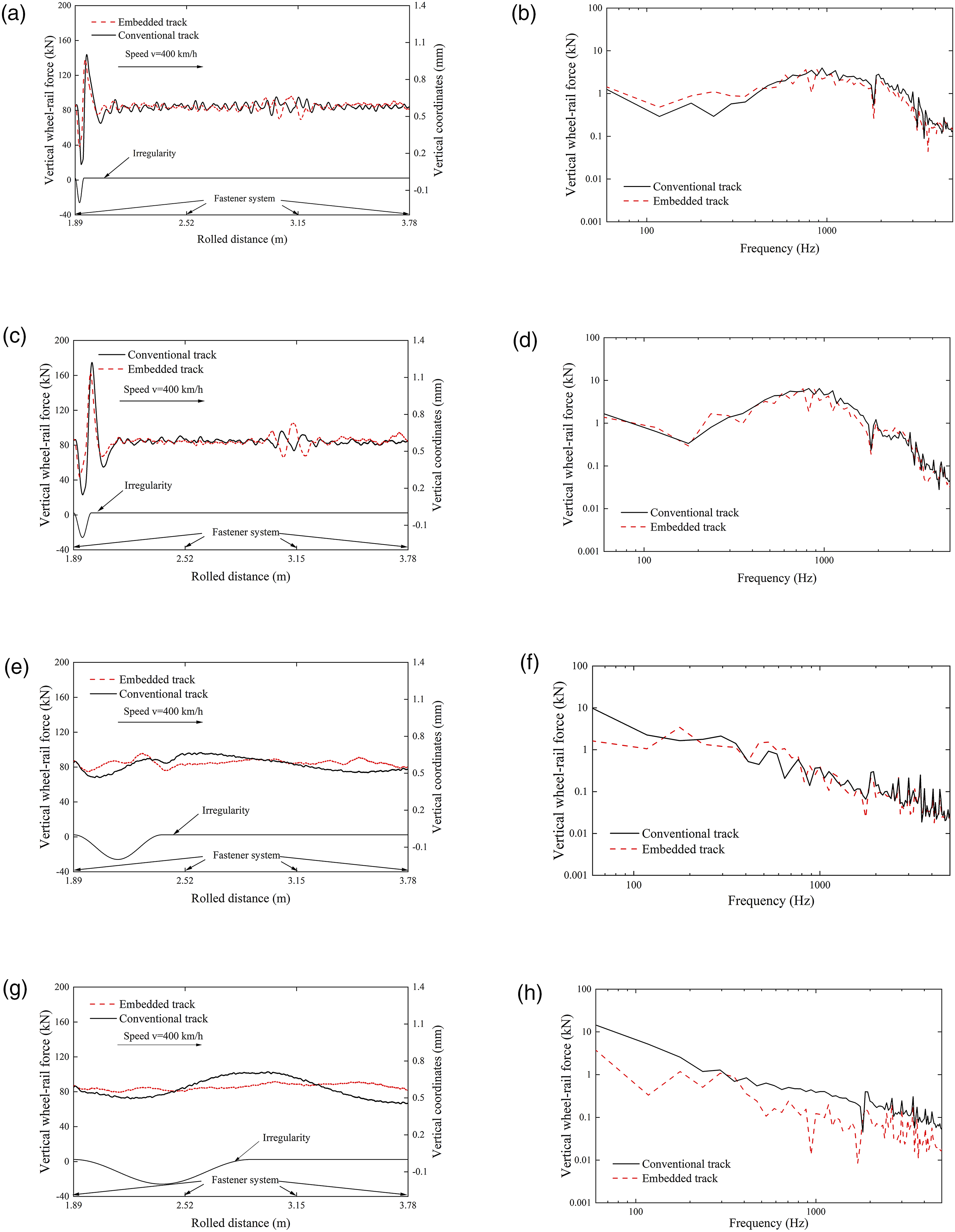
The following insights can be derived from Figure 16: (1) Short wavelength impact: For shorter wavelengths approximately below 0.1 m, the embedded track and conventional track demonstrate comparable impact behaviors in the time domain. However, the impact generated by the embedded track is notably lower than that of the conventional track. (2) Long wavelength impact: For longer wavelengths approximately above 0.5 m, the composite integrity of the embedded track results in distinct impact behaviors compared to the conventional track. Specifically, the vertical wheel-rail force induced by the welded joint in the embedded track is significantly lower than that in the conventional track. (3) Frequency spectra analysis: The vertical wheel-rail force frequency spectra indicate that, for shorter wavelengths, the low frequency differences between the embedded track and conventional track are minimal. In this range, the vertical wheel-rail force of the embedded track may even slightly exceed that of the conventional track. However, at higher frequencies, the embedded track exhibits a lower amplitude in vertical wheel-rail force, suggesting that the embedded track effectively suppresses high-frequency vertical wheel-rail interaction forces. (4) Effect of increasing wavelength: As the wavelength increases, the embedded track’s frequency response improves, effectively suppressing vertical wheel-rail impact force caused by long wavelengths. This highlights the embedded track’s superior performance in reducing long-wave-induced vertical wheel-rail impact forces.
To further analyze the effect of the embedded track on vertical wheel-rail impact force, Figure 17(a) illustrates the peak and valley values of wheel-rail force in the time domain for both the embedded and conventional tracks (solid lines represent peak values, while dotted lines denote minimum values). Given that fluctuations in vertical wheel-rail force effect vehicle operational safety, Figure 17(b) presents a comparison of load reduction rates for the embedded track and conventional track, based on the wheel weight reduction rate as specified in GB/T 5599-2019. The amplitude of the vertical wheel-rail impact force. (a) Force peak and valley. (b) Wheel load reduction rate.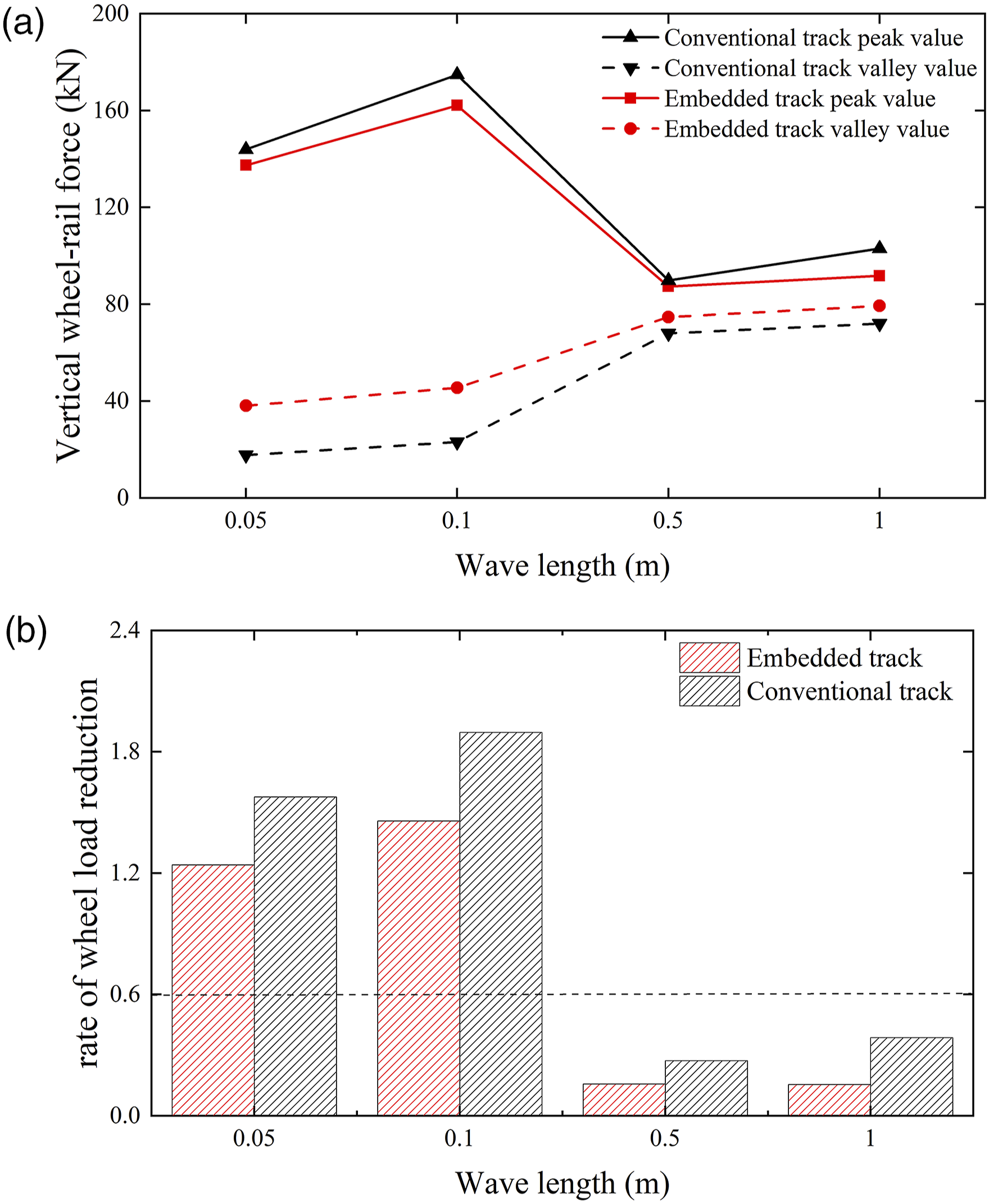
The following conclusions can be drawn from Figure 17: (1) Impact force amplitude behavior: The impact force amplitude of both the embedded track and conventional track follows the same trend with respect to wavelength. As the wavelength increases, the wheel-rail impact force amplitude initially rises and then declines. At a wavelength of 0.05 m, the peak impact force of the embedded track is 6 kN lower than that of the conventional track, while the difference in valley values is 20 kN. (2) Fluctuation in load reduction rate: The analysis reveals that the embedded composite track exhibits a lower wheel weight load reduction rate compared to the conventional track system. This reduced load reduction rate enhances the operational safety of trains by mitigating impact force amplitude fluctuations.
Effect of the embedded track on the vibration acceleration of the axle box
To examine the vibration effect of the embedded track on the axle box, Figures 18(a), (c), (e) and (g) illustrate the axle box vibration acceleration under a wave depth of 0.001 m, effected by welded connectors at wavelengths of 0.05, 0.1, 0.5, and 1 m, respectively. The corresponding frequency spectra of the axle box vibration acceleration are shown in Figures 18(b), (d), (f), and (h). Vibration of axle box in time and frequency domains. (a) Time domain (wavelength 0.05 m). (b) Frequency domain (wavelength 0.05 m). (c) Time domain (wavelength 0.1 m). (d) Frequency domain (wavelength 0.1 m). (e) Time domain (wavelength 0.5 m). (f) Frequency domain (wavelength 0.5 m). (g) Time domain (wavelength 1.0 m). (h) Frequency domain (wavelength 1.0 m).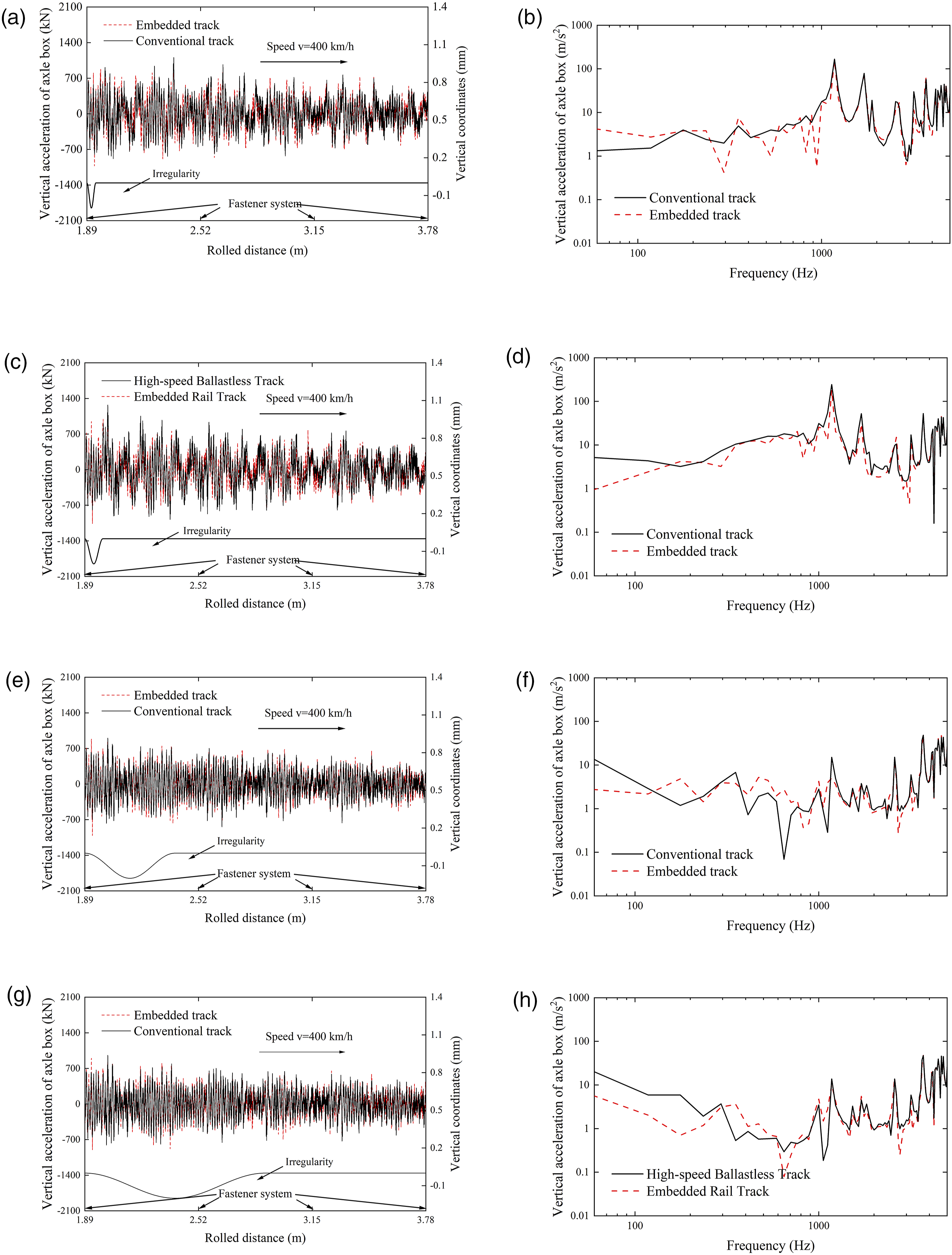
The following insights can be drawn from Figure 18: (1) Time domain analysis: The vibration acceleration of the axle box on the embedded track is lower than that on the conventional track, indicating that the embedded track effectively reduces axle box vibration. (2) Frequency domain analysis for short wavelengths: In the vibration acceleration frequency spectra, for shorter wavelengths, the difference in axle box vibration acceleration between the embedded track and conventional track is minimal. However, in the low frequency range, the axle box vibration acceleration of the embedded track slightly exceeds that of the conventional track. (3) Frequency domain analysis for increasing wavelengths: As the wavelength increases, the frequency response of wheel-rail impact force for the embedded track gradually shows improved performance over the conventional track. Consequently, the axle box vibration acceleration frequency response for the embedded track becomes progressively lower than that of the conventional track, highlighting the embedded track’s effectiveness in mitigating wheel-rail impact force induced by longer wavelengths.
The analysis in Figure 18 is mainly based on the finite element model that does not consider the porosity of the material. According to the two-scale fractal vibration theory, the porosity has an effect on the low-frequency vibration, and this theory can be further used to carry out the low-frequency vibration analysis in the subsequent analysis. 27
Conclusion
This study addresses the challenges of non-linear vibration and impact within the train-embedded track composite structure. First, the embedded track structure was designed based on stress–strain conditions, followed by an analysis of component effects on system parameters. Material testing and small-sample system tests were then conducted, combining these with a simulation-based predictive model to verify the model’s accuracy. The comprehensive test results confirmed the model’s reliability and validity. Finally, the calibrated model was used to predict the non-linear vibration and impact characteristics of the train-embedded track composite structure, leading to the following conclusions: (1) Effect on system stiffness and damping: The rail pad significantly effects the system’s vertical stiffness, while the elastic block and filling material have minimal effect on vertical stiffness. Conversely, the elastic block and filling material substantially effect horizontal stiffness, whereas the rail pad has negligible effect. The loss factors of the filling material and rail pad have a substantial effect on the modal damping ratio of the embedded track system, while elastic block has minimal effect on system damping. (2) Dynamic stiffness response to frequency: The dynamic stiffness of the embedded track structure increases with loading frequency. Below 10 Hz, dynamic stiffness rises sharply; whereas beyond 10 Hz, it stabilizes at a constant value, indicating that under high-frequency excitation, vertical stiffness variations in the embedded track specimen are negligible. (3) Equivalent damping ratio (ζ): The equivalent viscous damping ratio ζ of the embedded track exhibits a linear increase with loading frequency, consistent with Rayleigh damping’s proportional relationship to stiffness damping. At a loading frequency of 1 Hz, the equivalent viscous damping ratios for various prepressures converge at approximately 0.027; at 40 Hz, the ratio reaches 0.186. (4) Frequency spectra of wheel-rail impact force for short wavelengths: For shorter wavelengths, low-frequency differences in wheel-rail impact force between the embedded track and conventional track are negligible. At low frequencies, the embedded track’s wheel-rail force may slightly exceed that of the conventional track; however, at high frequencies, the embedded track’s wheel-rail force amplitude is lower, suggesting effective suppression of high-frequency wheel-rail interaction forces. (5) Frequency spectra of wheel-rail impact force for longer wavelengths: As the wavelength increases, the embedded track’s frequency response to wheel-rail impact force demonstrates significant improvement compared to the conventional track, with notable effectiveness in mitigating long-wave-induced wheel-rail impact force.
The dynamic stiffness/damping characteristics of embedded track considered in this study mainly focus on the study of low frequency dynamic characteristics. In the subsequent study, the dynamic stiffness/damping characteristics of middle and high frequency can be further considered to analyze the effect of dynamic stiffness/damping characteristics on the vibration and acoustic radiation characteristics of embedded track.
Footnotes
Declaration of conflicting interests
The author(s) declared no potential conflicts of interest with respect to the research, authorship, and/or publication of this article.
Funding
The author(s) disclosed receipt of the following financial support for the research, authorship, and/or publication of this article: This study was supported by the National Natural Science Foundation of China (52002340), the Fundamental Research Funds for the Central Universities (2682024CG007).