
Abstract
The transient vibration and noise of cabins are crucial contents in cruise comfort design. At present, there is no general calculation method or evaluation standard for transient acoustic performance of cruise cabins. The frequency response analysis method, based on harmonic unit force excitation, cannot sufficiently consider the initial state and damping effect stage of various transient problems, making it difficult to evaluate the performance of transient vibration and noise. In this paper, a general time-domain virtual tapping machine method for numerical evaluation of transient acoustic performance in cruise cabins is proposed. Firstly, a rigid-flexible coupling numerical model between the virtual tapping machine and cruise cabins is established, and the time-domain virtual transient force with a broadband spectrum is obtained. Secondly, the transient vibration and noise of typical cruise cabins are numerically analyzed based on the coupled time-domain finite element method and boundary element method (TDFEM/BEM) and virtual mode synthesis and simulation (VMSS). The low-frequency results are obtained based on the coupled TDFEM/BEM, while the high-frequency results are obtained using the VMSS. Finally, a standard based on single-number quantities (SNQs) is proposed to evaluate the transient acoustic performance of cruise cabins. The effectiveness of the time-domain virtual tapping machine method is verified by real ship tests. The numerical results are consistent with the trend of the test results, and the total level error of the cabin transient noise is within 3 dB. The results demonstrate that the time-domain virtual tapping machine method can accurately calculate the transient response of cabins and quickly evaluate their transient acoustic performance. This paper presents a method for predicting the transient vibration and noise performance in the cabin of cruise ships during the design stage. This approach addresses the gap in the prediction and evaluation of transient noise performance in large cruise ships and provides essential technical support for the acoustic comfort design of luxury cruise ships.
Keywords
Introduction
With the advancement of ship design, higher standards1–4 for ship comfort are being established, transitioning from controlling steady-state noise comfort5–9 to managing both steady-state and transient noise comfort. As high-value-added products, cruise ships demand higher standards for vibration and noise comfort. Besides conventional vibration noise sources, such as steady-state mechanical noise from main engines, auxiliary engines, and propellers, cruise ships encounter numerous complex transient vibration noise sources, including mooring noise, vacuum toilet noise, 10 and entertainment noise. 11 The randomness, diversity, and broadband characteristics of these transient vibration and noise sources increase the complexity of predicting transient noise in cruise cabins. Currently, research on ship vibration and acoustic radiation mainly focuses on steady-state vibration and noise. However, there are few studies on evaluating the transient vibration and noise performance of cruise ships under transient excitation, highlighting the urgent need for relevant research.
To efficiently and economically design and optimize the vibration and noise reduction performance of cruise cabins during the design stage, it is essential to perform efficient calculations and accurate numerical predictions of broadband transient vibration and sound radiation. Experimental testing of numerous alternative configurations is both expensive and time-consuming. However, achieving efficient and reliable predictions and evaluations presents two challenges: generating and predicting broadband transient forces, predicting broadband transient vibration and noise performance for cruise ships, and evaluating the transient noise of cruise ships.
The first challenge is to generate broadband transient excitations on cruise ships and reasonably predict the impact force. In the prediction of steady-state frequency response, the standard method is to use unit harmonic force analysis to evaluate the steady-state vibration and acoustic performance of structures. However, the steady-state frequency-domain method tends to omit peaks and has low solution efficiency when addressing transient problems. Additionally, the conversion from the time domain to the frequency domain using Fourier transform may introduce winding errors, affecting calculation accuracy. 12 Therefore, it is necessary to introduce the time-domain transient load to calculate the transient response of the cruise ship and evaluate the structural vibration and cabin acoustic performance based on the transient response results. According to the ISO 10,140-5 standard, 13 the ISO tapping machine is used as a standard load source for actual impact noise measurement and building performance evaluation. The time-domain impact force generated by the ISO tapping machine has broadband characteristics in the frequency domain. The transient impact force generated by the standard hammer is affected by the momentum change of the hammer and the impedance of the struck structure. Cremer et al. 14 first provided the classical model of the ISO tapping machine, while Rabold et al. 15 summarized the four classical excitation force models of the tapping machine impacting the plate. To simplify the calculation, Qian et al. 16 and Song et al. 17 considered the amplitude spectrum of the impact force generated by a single hammer impacting a rigid structure to be constant. Lietzén et al. 18 measured the transient impact force by modifying the ISO tapping machine, but the related tests were complicated and expensive. For complex systems with uncertainty, Zhou et al. 19 proposed the use of deep recurrent neural networks to identify the impact load of nonlinear structures, providing a novel approach to impact load identification. However, the limitation of this method is that it requires a large number of response datasets for training. 20 Feng et al.21,22 proposed a gear wear prediction scheme based on vibration analysis. In summary, the complexity of theoretical analysis presents certain limitations when dealing with large and complex structures, rendering it suitable only for simple models. Additionally, full-scale ship testing for cruise ships is challenging and costly, and there is a lack of sufficient experimental data. Rigid-flexible coupling multi-body dynamics can account for the influence of flexible body deformation on the system’s dynamic response and can be applied to complex structures. It has many applications in the fields of aerospace23,24 and vehicle 25 dynamics. Therefore, based on the rigid-flexible coupling dynamics theory and the improved Craig–Bampton method, a rigid-flexible coupled dynamics numerical model is established for the impact analysis of the virtual ISO tapping machine and the complex structure of the cruise ship cabin. This model predicts the broadband transient excitation of the cruise ship cabin.
The second challenge is the prediction and evaluation of broadband transient vibration and noise performance in cruise cabins. In the field of transient vibration and noise theory and numerical research, Yufang and Zhongfang 26 and Troccaz et al. 27 combined Hertz contact theory to provide an analytical solution for structural transient vibration and acoustic radiation theory under simple conditions such as cylinder collision and ball impact plate. Li et al. 28 used the finite element method and the transient boundary element method to study the cylindrical collision and impact noise through numerical analysis. Structural vibration and noise under the excitation of the ISO tapping machine are studied by empirical method and experimental method.29–31 Zou et al.32,33 studied the vibro-acoustic characteristics of a coupled nonlinear system of cylindrical shells in air and underwater, and calculated the external sound field using the time-domain boundary element method (TDBEM). Gao et al.34,35 investigated the transient vibration of stiffened plates and experimentally studied the underwater radiated noise of cylindrical shells under broadband excitation. Qu et al. 36 studied the acoustic characteristics of composite laminates under moving loads based on the TDBEM. In summary, the time-domain method achieves higher accuracy when dealing with pulse signals, impact signals, and short-term aperiodic broadband signals, while also considering the nonlinearity of structure, load, and boundary conditions. The time-domain finite element and boundary element methods have more advantages in addressing transient low-frequency vibration and noise problems.
The frequency range corresponding to transient excitation on cruise ships is wide, and the transient response of vibration and noise in the whole frequency band cannot be accurately predicted using the FEM or SEA alone. Bard et al. 37 established a low-frequency FEM model and used the high-frequency SEA model to analyze the transient vibration and acoustic radiation of wood floors. Cho 38 used the hybrid FEM and SEA to study the low-frequency vibration acoustic characteristics of floating floors. Zhang et al. 6 established the low, medium, and high frequency acoustic-vibration coupling model for the oil tanker cabin, achieving predictions of steady-state noise across the entire frequency band using FEM, a hybrid FEM and SEA method, and SEA, respectively. For the high-frequency SEA, the power flow equation can only be applied when the subsystem is in steady-state vibration or at least quasi-static. This method has limitations when addressing transient high-frequency vibration under impact loads. Dalton39–41 proposed virtual mode synthesis and simulation (VMSS) to solve the problem of predicting transient response in high-frequency impact environments. Zhao et al.42,43 applied this method to predict the impact response of complex aerospace structures. The primary idea is to use the existing frequency response function envelope and related assumptions to calculate the modal shape parameters and synthesize an approximate real frequency response function. The VMSS makes up for the limitations of the FEM/BEM in solving the problem of excessive structural size and high frequency. In summary, research on the steady-state vibration and noise of ships is well-developed, while studies on the broadband transient vibration and noise of cruise ships under transient impact loads remain limited. Additionally, there are also few studies on evaluation criteria for transient noise in cruise cabins.
In this paper, the cabin of a large cruise ship is taken as the research object, and a time-domain virtual tapping machine method for predicting broadband transient vibration and noise performance of cruise cabins under transient impact is proposed. Firstly, a rigid-flexible coupling dynamic numerical model for impact analysis of the virtual ISO tapping machine and cruise cabin is established. The time-domain transient impact force with broadband characteristics is obtained by numerical calculation and used as the transient excitation source of the cruise cabin. Subsequently, the transient vibration and noise of the cruise cabin under the virtual transient impact force are calculated. In the low-frequency band (20 Hz–315 Hz), the analytical gradient mesh model of the cruise cabin is established, and the transient response is solved by the coupled TDFEM/BEM. In the high-frequency band (315 Hz–4000 Hz), a statistical energy model is established, and the transient response of the structure is solved based on the VMSS. Finally, according to the ISO 717-2 standard,
44
SNQs are proposed as a standard to evaluate the transient acoustic performance of cruise cabins. The effectiveness of the time-domain virtual tapping machine method is verified by actual ship tests. The process of calculating and evaluating the transient noise of cruise cabins under the broadband transient excitation of the virtual tapping machine is illustrated in Figure 1. The transient noise prediction and evaluation process for cruise cabins under transient excitation of virtual tapping machine.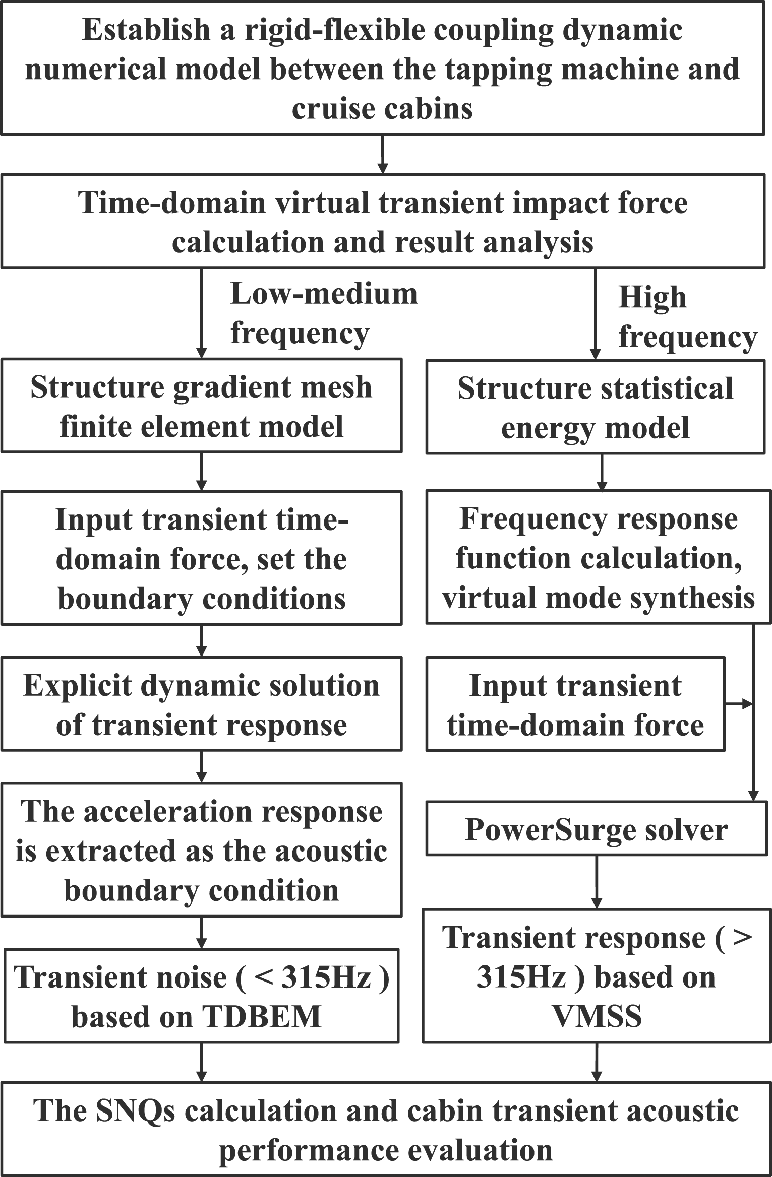
Time-domain virtual tapping machine method
The rigid-flexible coupling dynamic numerical model of the ISO tapping machine and structure
According to the ISO 10,140-5 standard, the ISO tapping machine is composed of five steel cylinders (hammers) with a diameter of 0.03 m, a mass of 0.5 ± 0.1 kg, and an arc bottom. The spacing of each hammer is 0.01 m. The five hammers are numbered from 1 to 5 and impact the structure in the sequence 1-3-5-2-4. Each hammer has a single impact period of 0.5 s, a continuous impact time interval of 0.1 s, and the impact frequency is Schematic diagram of the ISO tapping machine.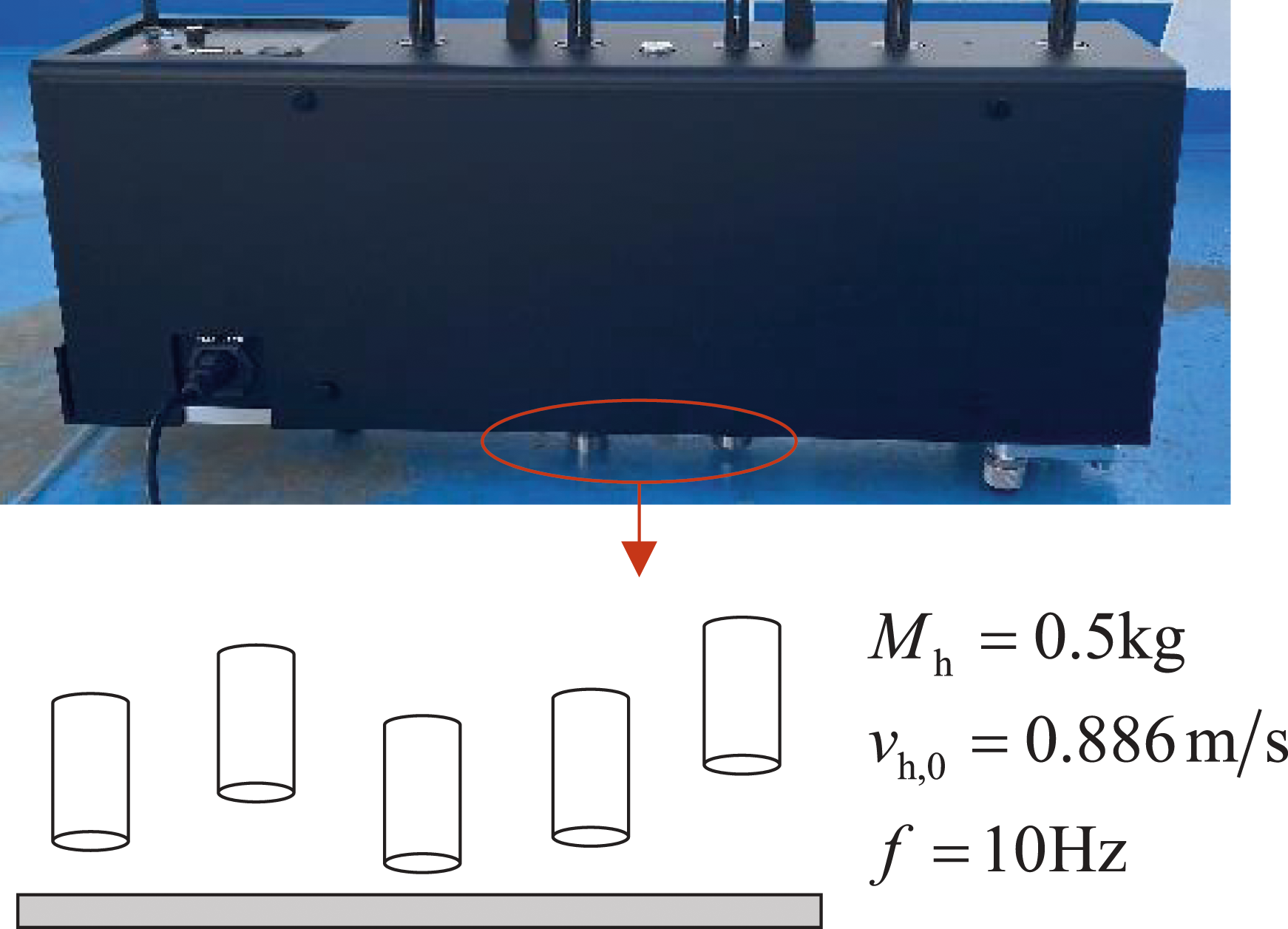
The theoretical model of impact force analysis of the ISO tapping machine-the floor
The model shown in Figure 3 was proposed by Brunskog and Hammer
45
to depict the single excitation of the ISO tapping machine hammer on a finite floor. A single impulse force can be expressed as Model of a single impact of an ISO tapping machine on a finite floor in the frequency domain.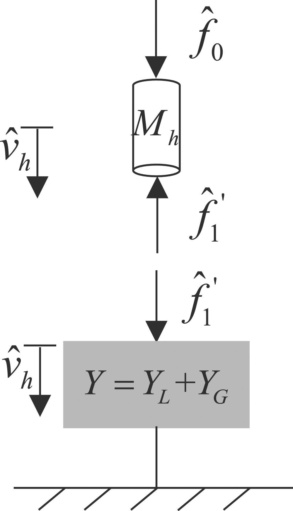

The floor at the contact point has the same velocity as the hammer, so the equation of motion at the point of contact can be expressed as follows


The time-domain acceleration of the hammer is obtained by inverse Fourier transform, and combined with

The rigid-flexible coupling dynamic numerical model of the ISO tapping machine-the floor
To address the issue of virtual transient force of the ISO tapping machine in complex structures, a rigid-flexible coupling dynamic numerical calculation model of the ISO tapping machine and structure is established. The modeling and analysis process of the rigid-flexible coupling dynamic model is illustrated in Figure 4. The modified Craig–Bampton method is employed to form the modal vector and modal coordinates of the response, describing the deformation of the flexible body. The modal results are calculated using ABAQUS software and imported into LMS Virtual.Lab motion mechanism design to generate a flexible body, with the modal damping set to 0.03. The Contact tool is utilized to define the contact between the hammer and the structure. The modeling and analysis process of rigid-flexible coupling dynamic model.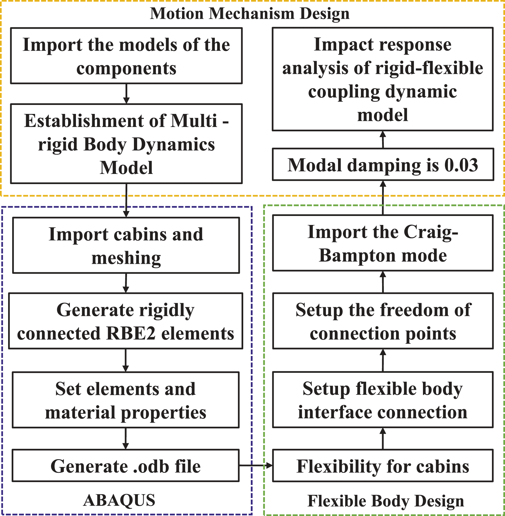
A key aspect of the numerical model is to simulating the motion process of the ISO tapping machine. The lifting mechanism is based on the isometric helix line, as shown in Figure 5. The hammer is associated with the lifting mechanism through appropriate kinematic subs, effectively controlling the motion of the entire model. In the lifting mechanism, the isometric helix rotates at a constant acceleration of 120 r/min, forcing the connecting rod to rise periodically along the isometric helix profile. The radial (vertical upward) velocity of the stable rising stage is Schematic design of the isometric spiral profile ( The setting of the parameters of the lifting mechanism. : Isometric spiral profile;
  : ascent trajectory;
  : falling trajectory).
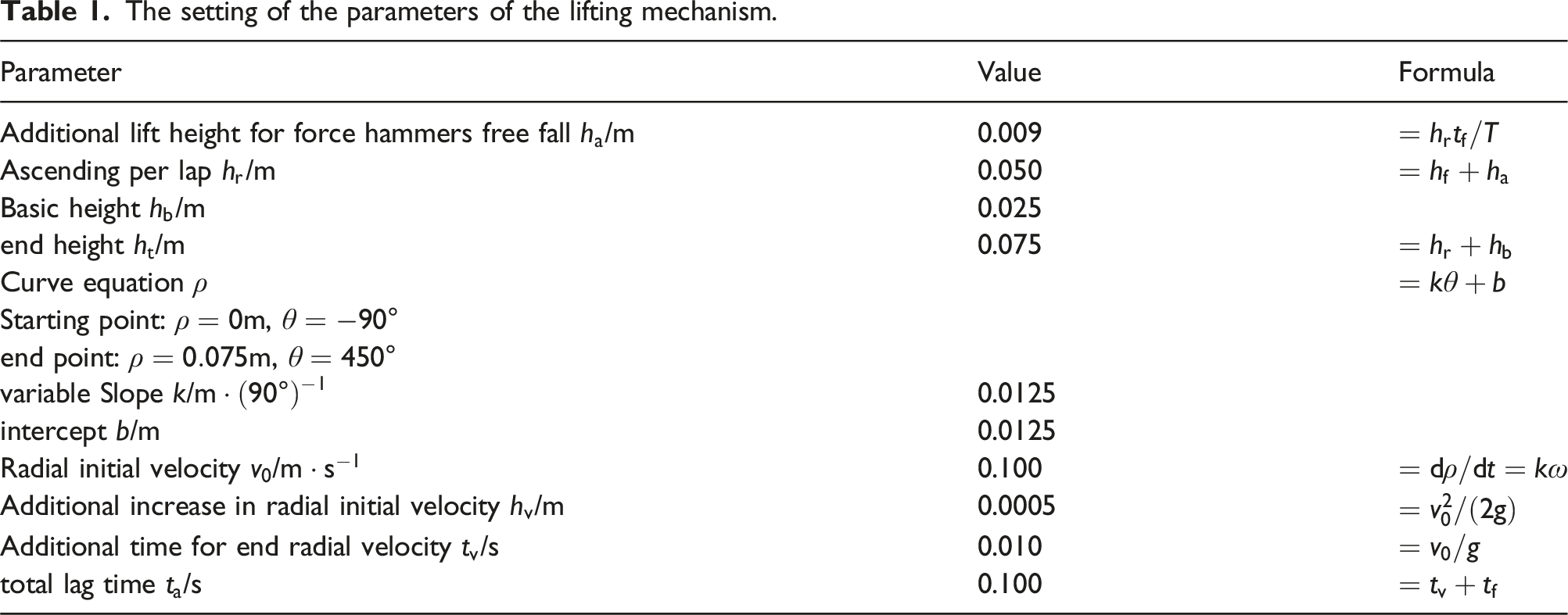
Figure 6 illustrates the velocity and displacement calibration values for the ISO tapping machine. The final velocity of the hammer falls within 0.886 ± 0.022 m/s. Except for the first impact, the final velocity of the hammer consistently reaches approximately 0.886 m/s, indicating that the kinematic parameters of the hammer meet the standard requirements. The hammer velocity and falling height of the ISO tapping machine.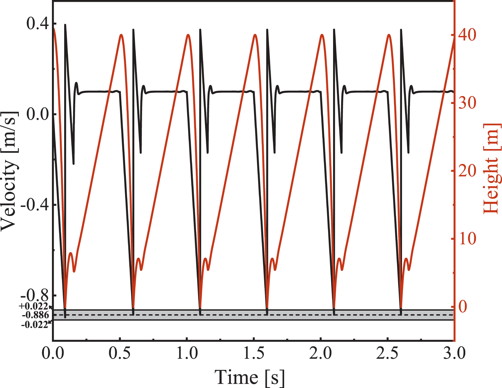
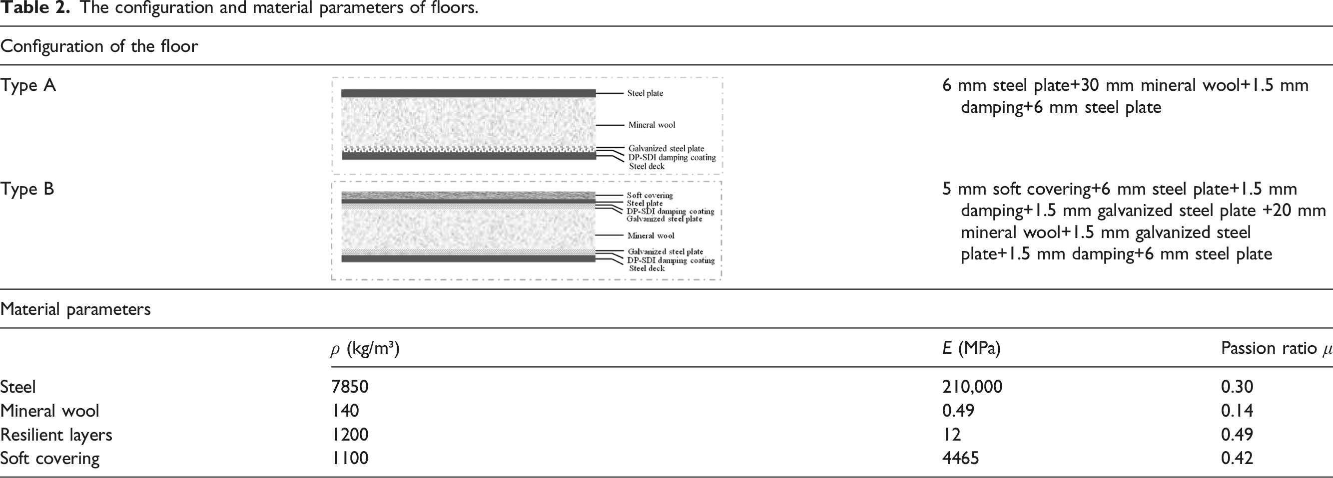
The finite element model of the plate is shown in Figure 7, with dimensions of 5.0 m × 2.8 m. The material parameters are listed in Table 2. To simulate the virtual impact force between the floor and the ISO tapping machine, the floor model is discretized into 24,264 linear solid elements. The results of the single impact force from both theoretical model and the numerical model are shown in Figure 8, demonstrating good agreement and verifying the accuracy of the numerical model. The finite element model of the plate. The configuration and material parameters of floors. Comparison of single impact force.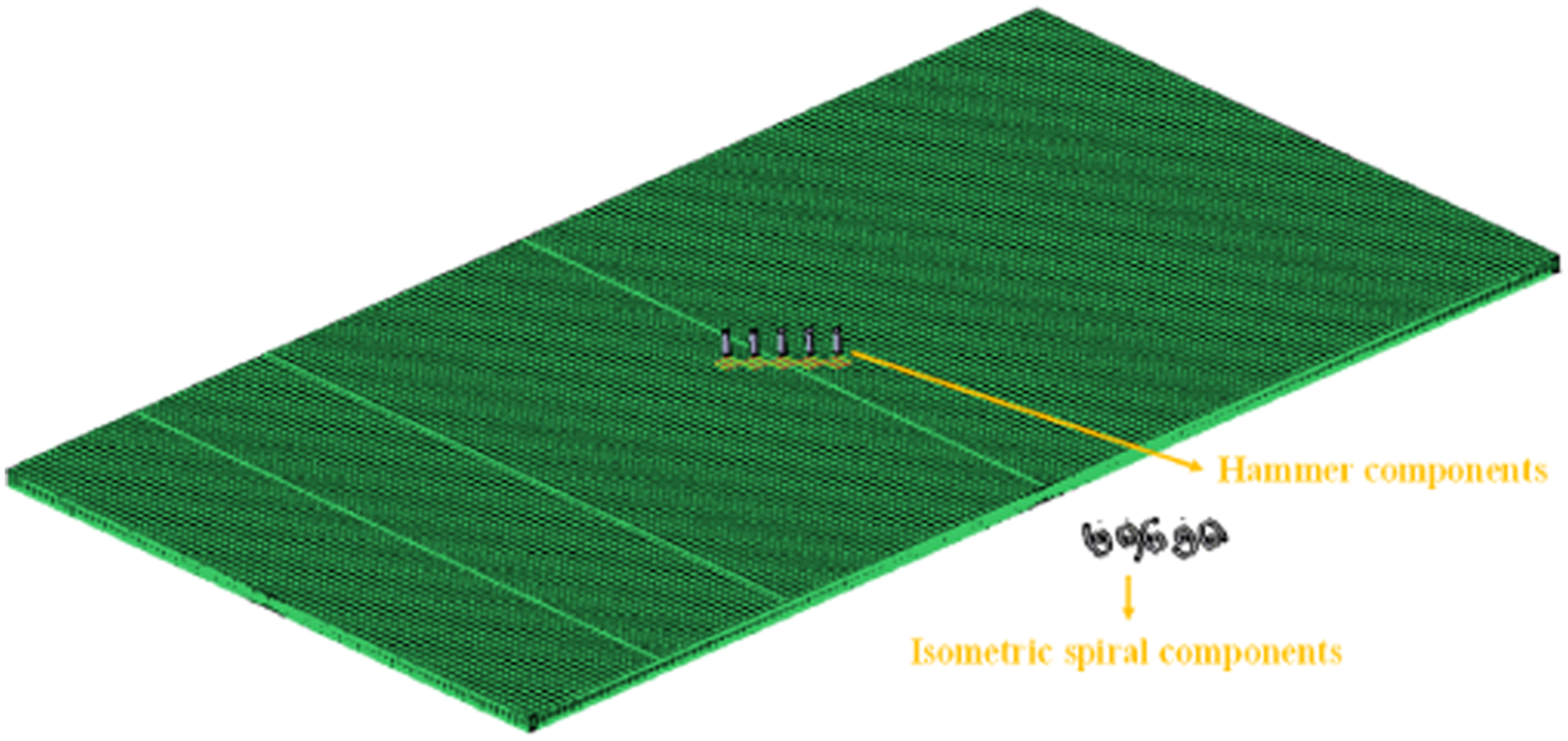
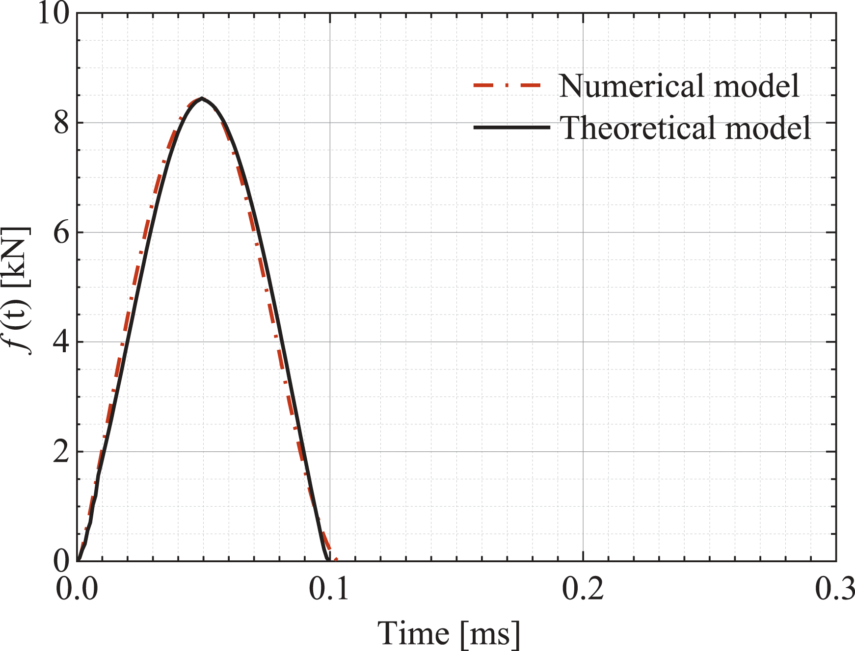
Although the theoretical model has advantages in addressing the impact of simple structures, it is challenging to directly extract the stiffness and mass matrix of the structure when dealing with the impact model of complex structures. Therefore, the rigid-flexible coupling numerical model used in this paper is more adaptable for obtaining the transient impact force of the tapping machine.
The coupled time-domain FEM/BEM for transient vibration and noise analysis
Under the excitation of a time-domain transient force, the dynamic equation of the structure is as follows
The cabin noise is solved by the TDBEM based on the wave theory. Assuming that there are small amplitude waves in the ideal uniform flow medium, the wave equation is
Under zero initial conditions, the well-known time domain boundary integral equation is derived from the wave equation
47
as follows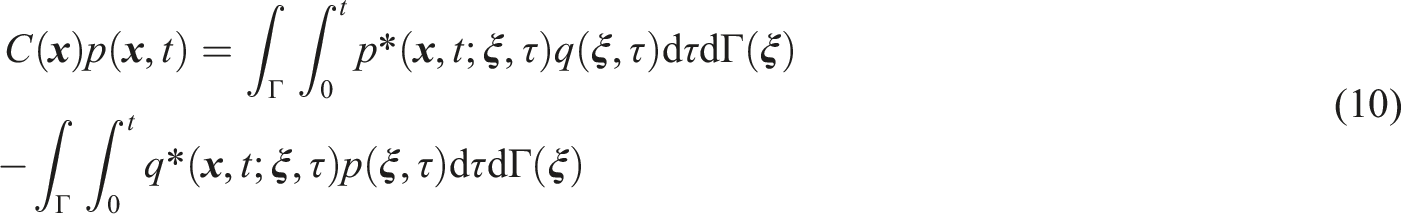
At the structure-acoustic medium interface 
It is difficult to obtain an analytical solution of equation (9). Thus, it is necessary to discretely interpolate equation (9) and determining the unknown quantities on its boundary. Moreover, the approximate solution for the unknown quantities on the discrete points of the boundary is obtained through numerical methods. Time discretization involves dividing the time interval
The discrete time-domain boundary integral equation can be written as follows
Virtual mode synthesis and simulation with high frequency characteristics
In the modal coordinates, equation (8) can be written as follows


The relationship between the acceleration response and the velocity response of the system is as follows
The acceleration frequency response function (FRF) can be descripted as

The amplitude of the acceleration FRF can be rewritten as

A series of discrete frequencies 

When the FRF envelope, structural modal number, and the input force function are obtained, the transient response of the cruise cabin can be calculated. The virtual mode synthesis of the plate is carried out in VA one software, and the transient impact response of the plate under the specified force function is calculated by the PowerSurge module, resulting in frequency-domain results. The structural acceleration response in the frequency domain is
Once the frequency domain response is obtained, and the results in time domain can be easily calculated by the inverse Fourier transform on the frequency results.
SNQs for cabin transient acoustic performance evaluation
There is no international standard for the evaluation of cabin transient acoustic performance. The SNQs for evaluating the transient acoustic performance of cruise cabins are proposed according to the ISO 717-2 standard, which converts frequency-related impact noise into the single-number quantities characterizing acoustic performance. Four SNQs are used to evaluate the acoustic performance: normalized impact sound pressure level
The normalized impact sound pressure level 
The weighted normalized impact sound pressure level
The spectrum adaptation term
The weighted impact sound pressure level attenuation
Numerical analysis of transient vibration and noise of cruise cabins
Model description
Cruise cabins vibrate under the transient excitation of the ISO tapping machine. The noise generated by the structural vibration is transmitted to the cabin below and propagate in all directions along the structure. The important cabins of the cruise are mainly concentrated in the superstructure of the bow, as indicated in the red box in Figure 9. Therefore, the bow cabins of the cruise are selected as the research object for transient vibration response and noise analysis, as shown in Figure 10(a). The structural area spans from the Deck 9 to the Deck 12, and includes the section from frame ribs 290 to 325 along the ship’s length. A detailed view of the test cabins is shown in Figure 10(b). The test cabins are located on the starboard side of the cruise ship, with dimensions of 5.6 m × 2.8 m × 2.8 m. The finite element model of a cruise. (a) The finite element model of a cruise and (b) the detail view of the test cabins: the floor of Type A (without soft covering).
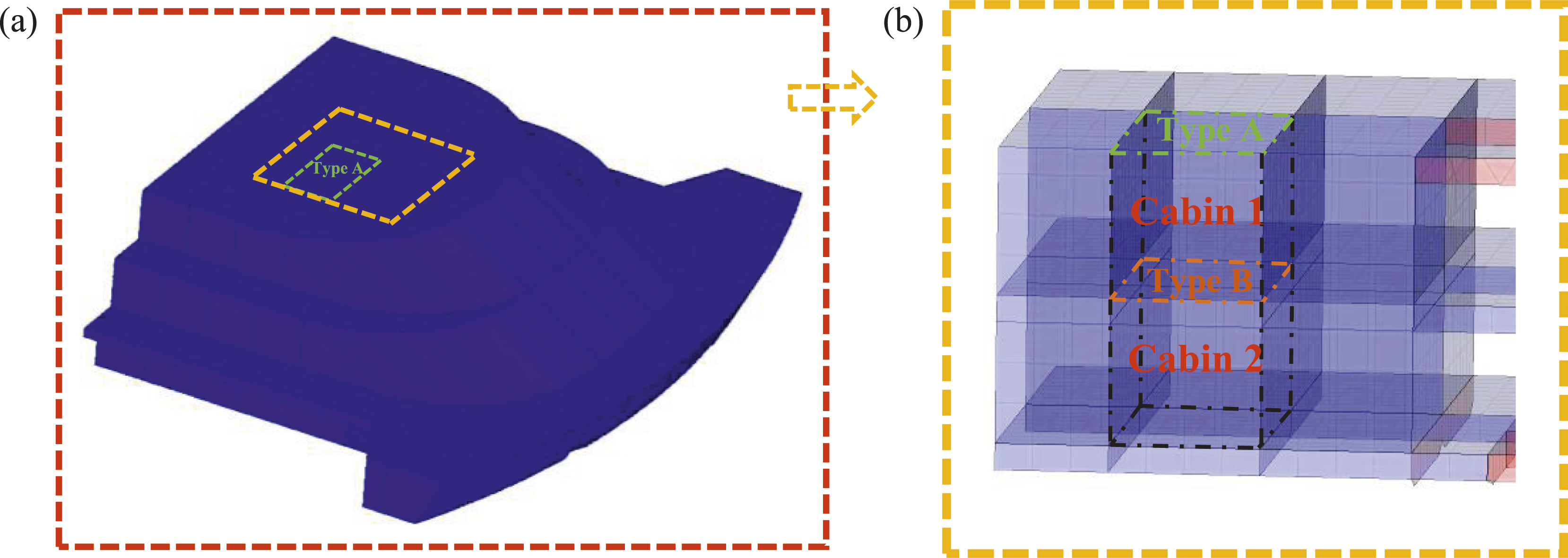
Type A (without soft covering) and Type B (with soft covering) floors are typical floor structures in cruise cabins. When the ISO tapping machine acts on both the Type A and Type B floors, Cabin 1 serves as the receiving cabin. When the ISO tapping machine acts on the Type B floor, Cabin 2 serves as the receiving cabin. When analyzing the vibration and noise response of the cabin structure under the excitation of the ISO tapping machine, the material properties of the impacted floor must be fully considered in the numerical model. The core layer is an important part of the floating floor, which should meet the cabin fire rating and acoustic rating specifications. The commonly used fire insulation core layer is mineral wool. To enhance the function of the floating floor in cruise cabins, damping materials can be laid on mineral wool. The combination of rock wool and damping improves the effectiveness of vibration and noise reduction. The structural dimensions and material parameters of the floating floor for each cabin are listed in Table 2.
Numerical model of broadband transient vibration and noise
Time-domain transient force calculation and analysis
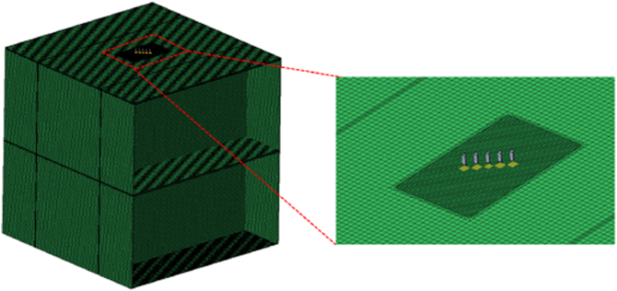
The time-domain transient force of the cabin floor under the excitation of the ISO tapping machine is calculated using the rigid-flexible coupling numerical model. The ISO tapping machine impacts the Type A and Type B floor at positions P1–P4, which are (1.40 m, 2.80 m, 0), (1.40 m, 1.40 m, 0), (0.90 m, 3.8 m, 0), and (1.90 m, 4.20 m, 0) in the local coordinate system, as shown in Figure 11. To improve computational efficiency, the impacted cabin and adjacent cabins are selected to establish a rigid-flexible coupling numerical model with the ISO tapping machine. The impacted cabin is flexible and discretized into 362,072 linear hexahedral solid elements. Since the bottom diameter of the hammer is only 0.03 m, the mesh is refined at each impact position, with a refined mesh size is 15 mm. Figure 12 shows the rigid-flexible coupling numerical model for Cabin 1. To simplify the calculation, the decoration on the side wall is omitted and defined as the damping layer, with a damping coefficient of 0.2. Impact positions P1–P4 and vibration acceleration measurement points. The numerical model of the impact model for Cabin 1.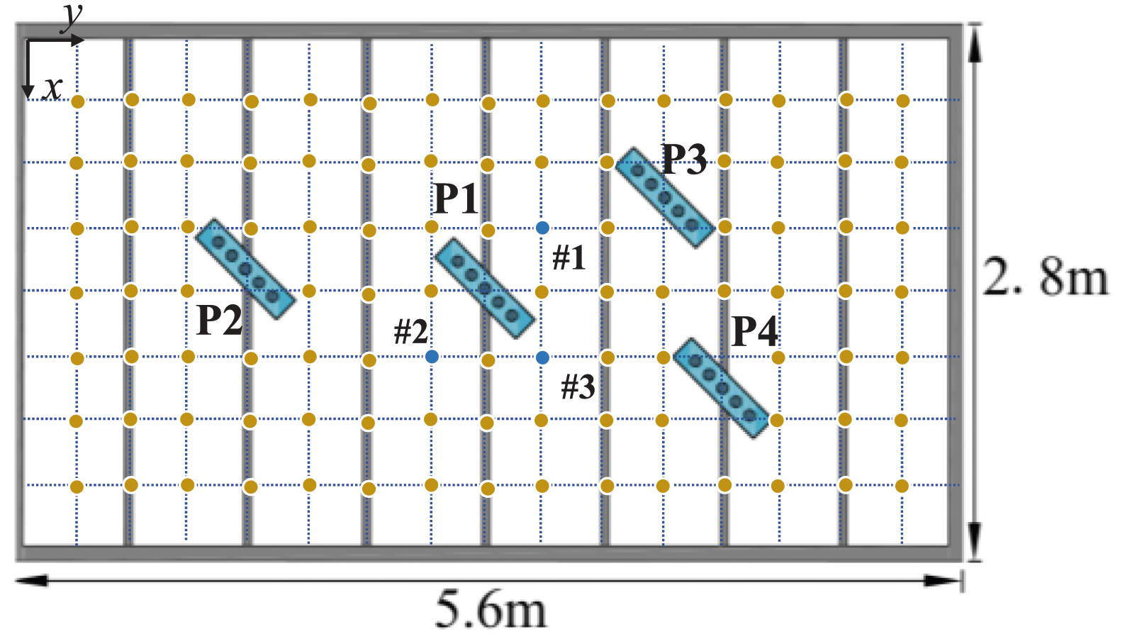
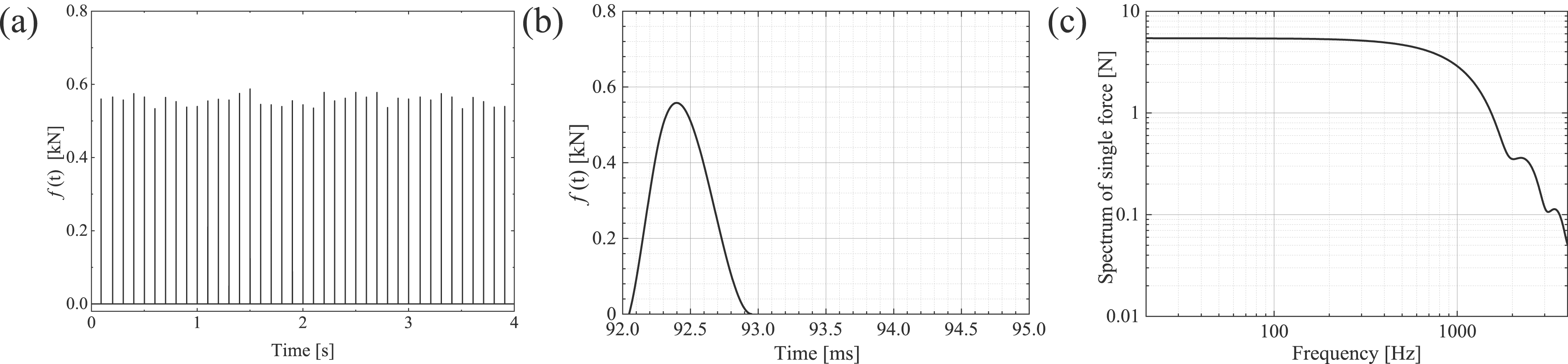
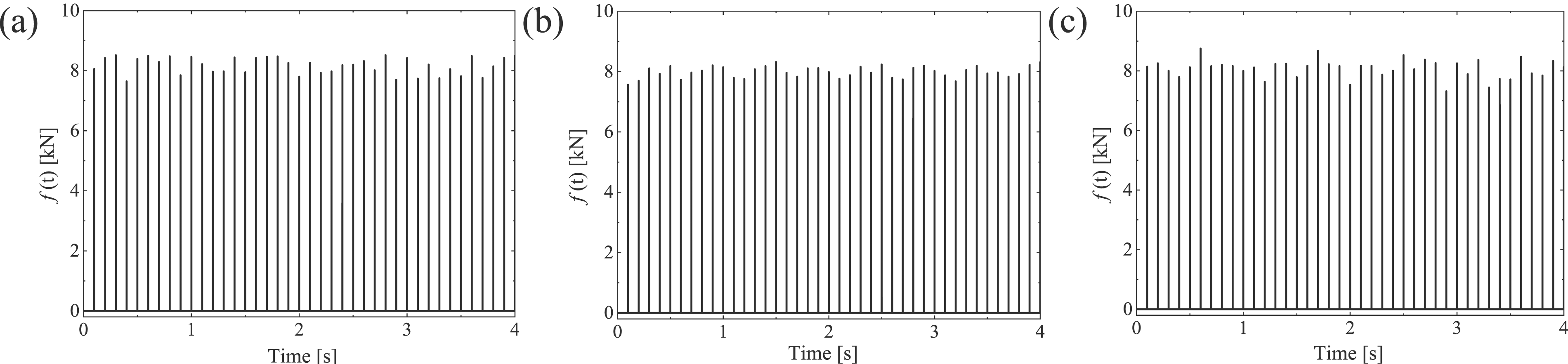
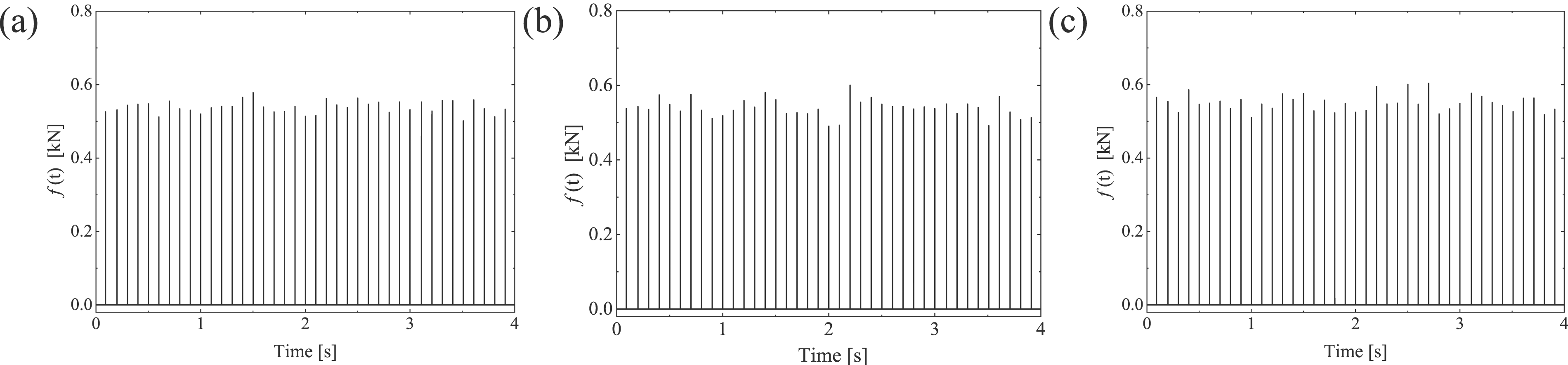
Since the position of the hammer is arbitrary at the beginning of impact, a complete initial impact force is not generated; therefore, the first impact force is omitted in the time history of the force. When the ISO tapping machine is located at P1, the transient virtual forces of the Type A and Type B floors are shown in Figures 13 and 14. Considering the accuracy of the transient force signal, a force pulse requires at least 20 sampling points with a time resolution The time history of Type A floor transient impact forces at P1 (a) The time-domain impact force; (b) The single impact force; (c) The force spectrum of single impact force. The time history of Type B floor transient impact forces at P1 (a) The time-domain impact force; (b) The single impact force; (c) The force spectrum of single impact force. Transient force excitation of the ISO tapping machine at P2–P4 of Type A floor (a) P2; (b) P3; (c) P4. Transient force excitation of the ISO tapping machine at P2–P4 of Type B floor (a) P2; (b) P3; (c) P4.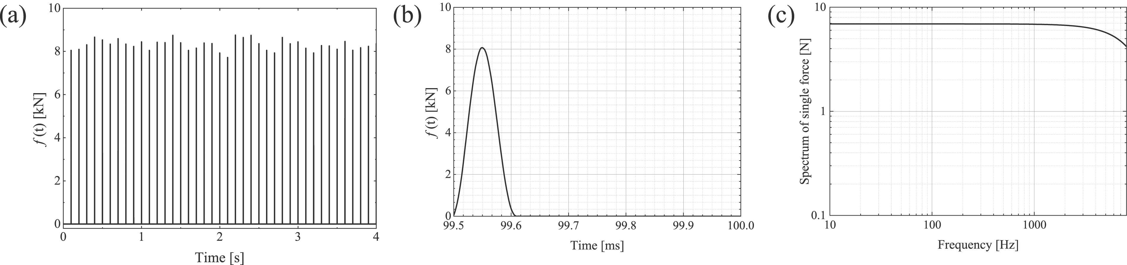
Numerical calculation model of transient vibration and noise of cruise cabins
In this section, the calculation frequency band is divided into two parts. The gradient mesh model is established for the low and medium frequencies (20 Hz–315 Hz), and the transient response is solved based on the coupled TDFEM/BEM. A statistical energy model is established for the high frequencies (315 Hz–4000 Hz) to solve the transient response based on the VMSS.
The finite element numerical calculation model of the bow cabins is shown in Figure 17. A simply supported boundary condition is applied at the truncation of the cabins. The transient force obtained is used as the external load excitation of the bow cabins, with the excitation positions being P1–P4. The vibration is primarily transmitted in the form of bending waves in the hull structure, attenuated by the damping effect of the structure. In regions closer to the source, structural vibrations are larger, and the vibration velocity attenuates faster, requiring more elements to describe the velocity accurately. In regions further from the source, structural vibrations are smaller and decay more slowly, allowing fewer elements to characterize the vibration velocity. To improve calculation efficiency, an analytical gradient mesh model
49
of the bow cabin is established, with an overall mesh size of 100 mm and a refined element size of 15 mm for the impacted cabin. The finite element numerical calculation model of the bow cabin.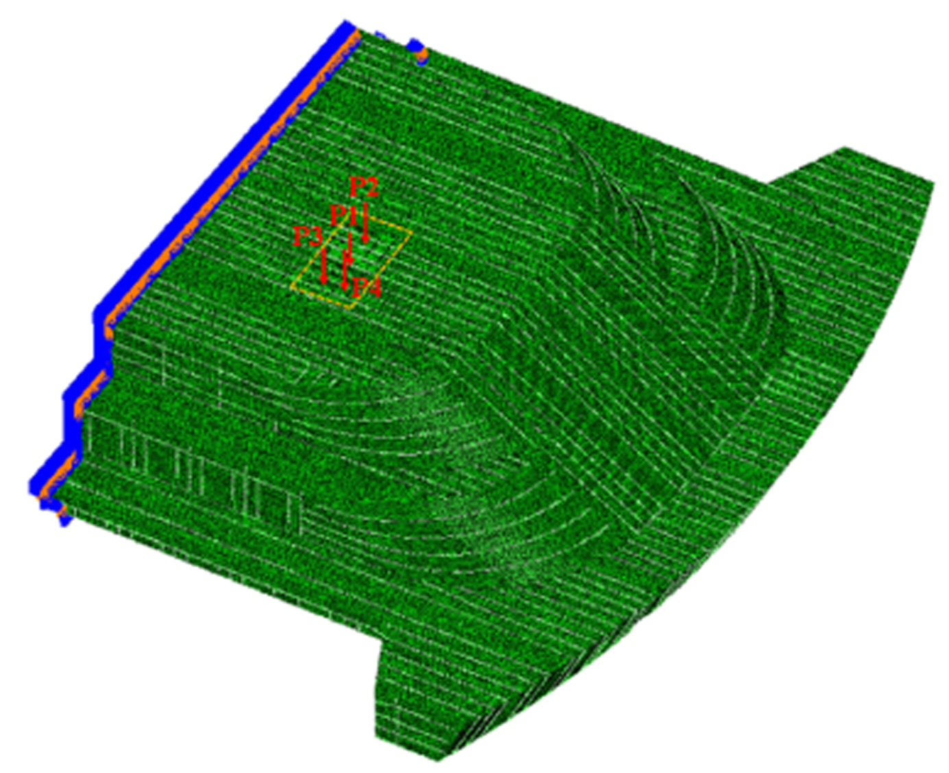
The primary material of cruise cabins is steel, with basic mechanical properties as follows: density
The TDBEM is used to analyze the acoustic radiation characteristics in the cabin at low and medium frequencies. Acoustic calculations are performed using LMS Virtual.Lab 13.6 software, and the transient vibration response (normal vibration acceleration) is used as the boundary condition for the acoustic calculation. The acoustic boundary element model of the impacted cabin is shown in Figure 18. The model requires at least six elements in the minimum wavelength range, with element sizes less than The boundary element model of the impacted cabin. The sound pressure measurement points in the receiving room.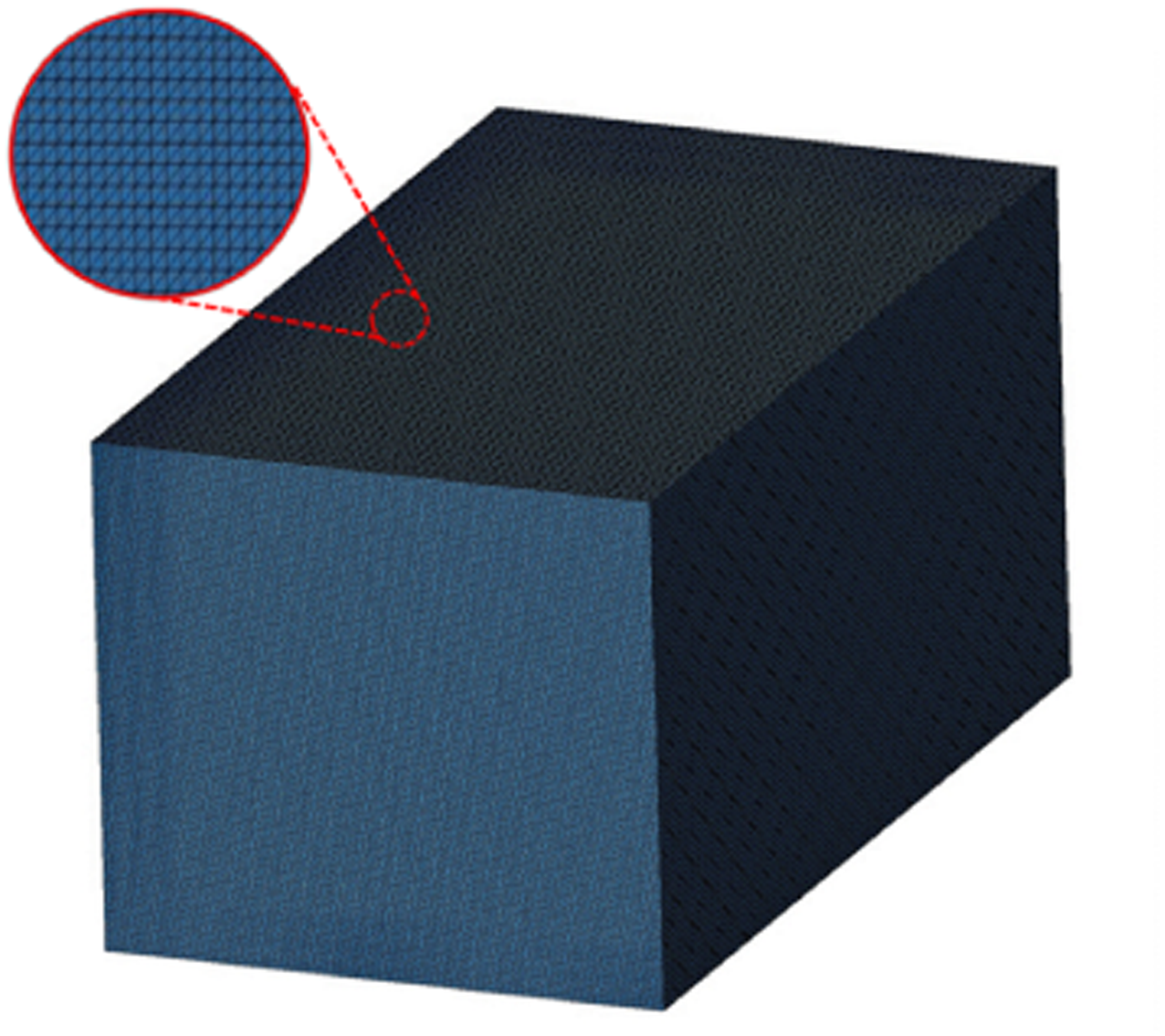
With the increase in calculation frequency, the FEM/BEM requires more elements and longer computation time. Due to the limitation of elements size and calculation scale, the finite element/boundary element numerical model becomes inapplicable. Therefore, the transient response of the bow cabin is predicted using the VMSS for the frequency band higher than 315 Hz. The statistical energy model of the bow cabin is shown in Figure 20. The damping characteristics of the structure are complex, and different components exhibit different damping characteristics. The damping loss factor is set to 3%, and the acoustic cavity loss factor is 1% in the one-third octave band of 315 Hz–4000 Hz. The statistical energy analysis model.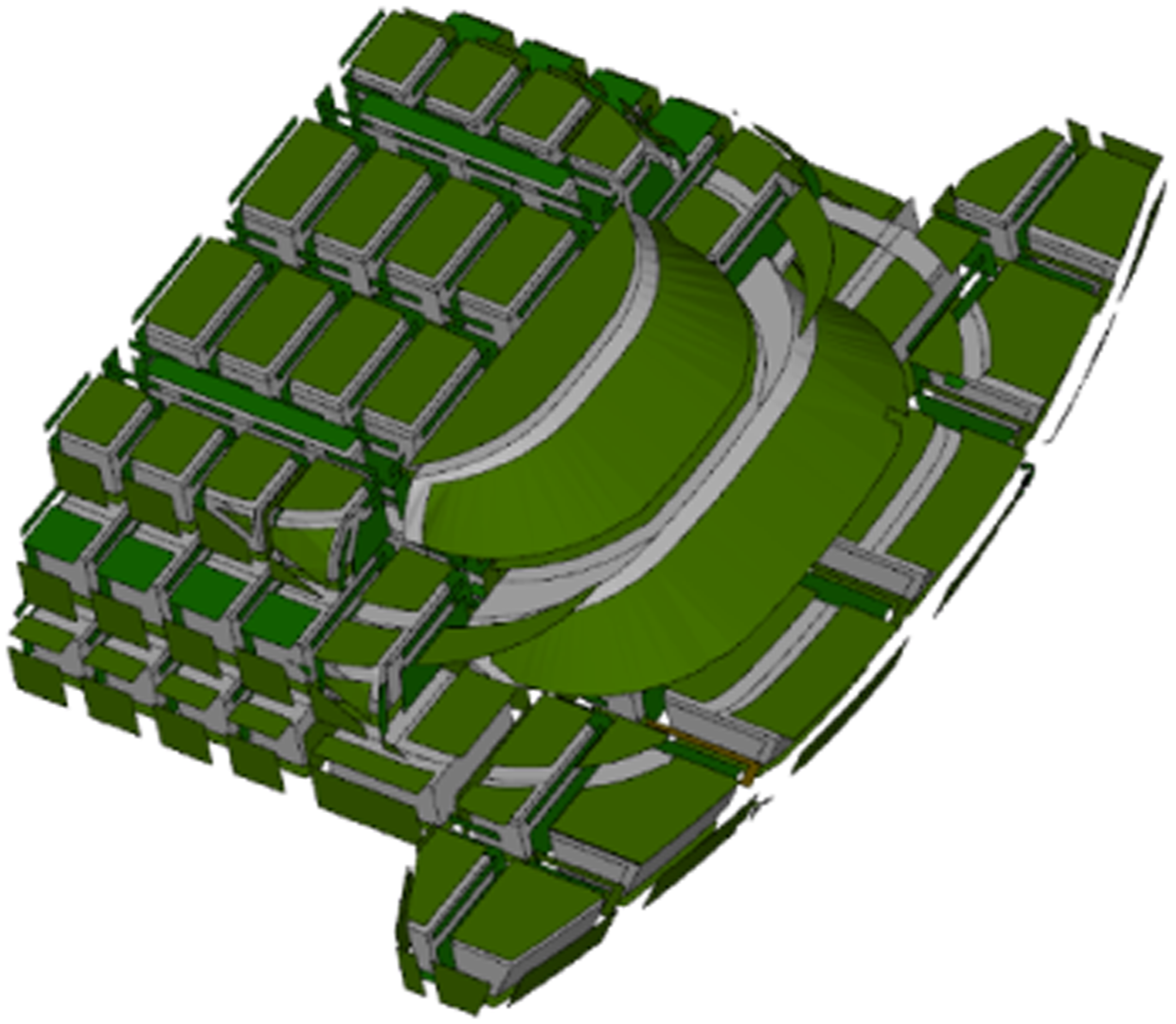
Transient vibration and noise results analysis and discussion
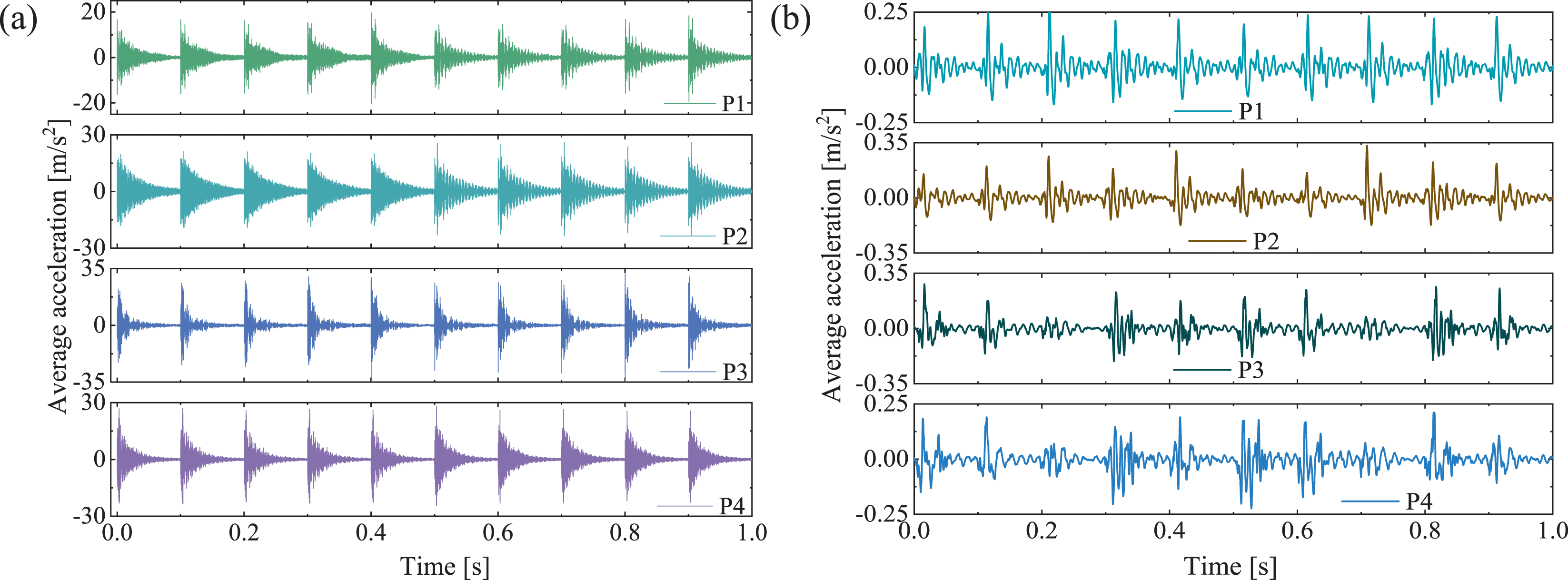
When the transient excitation source is located at the P1 position of the Type A and Type B floors, respectively. The vibration acceleration cloud of the cruise bow at t = 0.52 s is shown in Figure 21. The maximum value of the transient vibration response of the structure is mainly concentrated near the excitation source of the impacted cabin, and the bending wave continuously propagates outward, causing vibration in other cabins. The vibration in adjacent cabins is smaller than that in the impact source cabin, and the vibration decays rapidly with increasing of distance. The total time of the transient time-domain response analysis is 1 s. The vibration acceleration of the yellow measurement points in Figure 11 is averaged to obtain the time-domain average acceleration, as shown in Figure 22, which represents the overall vibration level of the impacted floor. The average acceleration satisfies the periodicity of 0.1 s. Since the vibration of the continuous impact is not completely attenuated, the vibration response of each 0.1 s impact cycle is not exactly the same. Vibration acceleration clouds of Type A and Type B floors at t = 0.52 s when impact source is located at P1 (a) Type A; (b) Type B. Time-domain average acceleration of two types of floors with impact source position at P1–P4 (a) Type A; (b) Type B.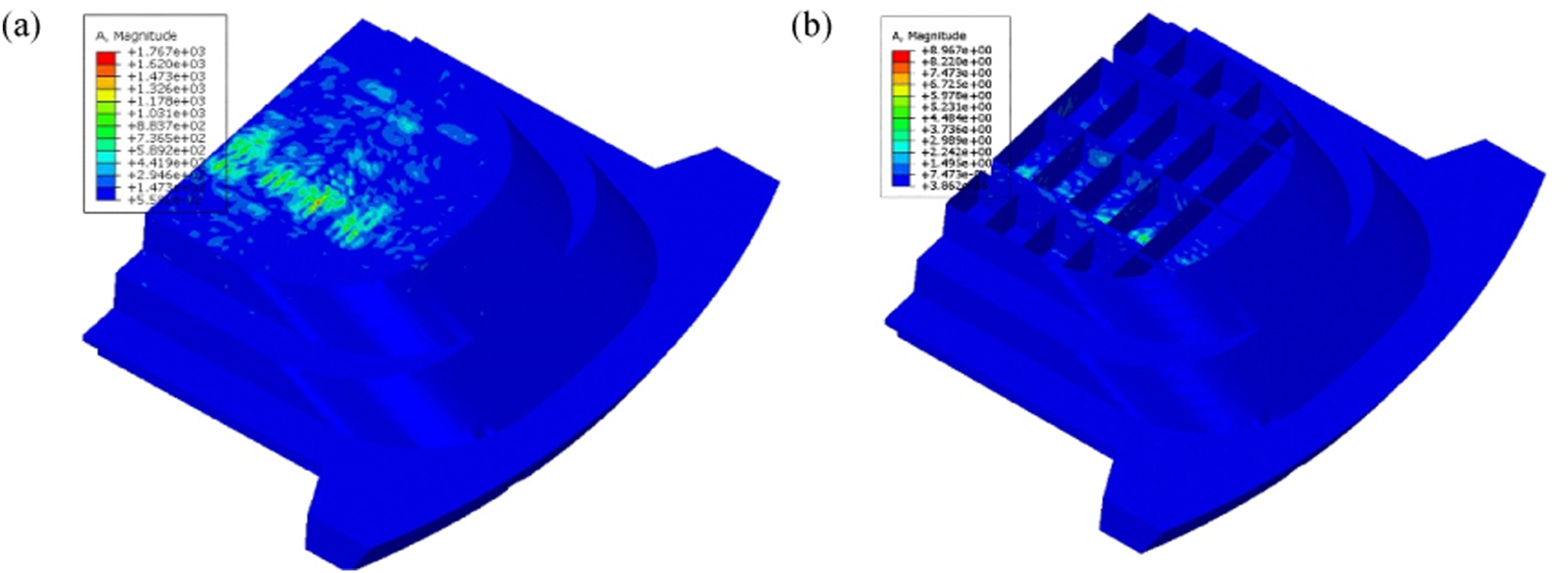
The time-domain response calculated by the TDFEM/BEM is subjected to FFT, resulting in numerical results for the frequency band of 20 Hz–315 Hz, while the VMSS provides numerical results for the frequency band of 315 Hz–4000 Hz. The one-third octave mean square acceleration levels of Type A and Type B floors are shown in Figure 23, with the reference acceleration denoted as The mean square acceleration levels of two types of floors (a) Type A; (b) Type B.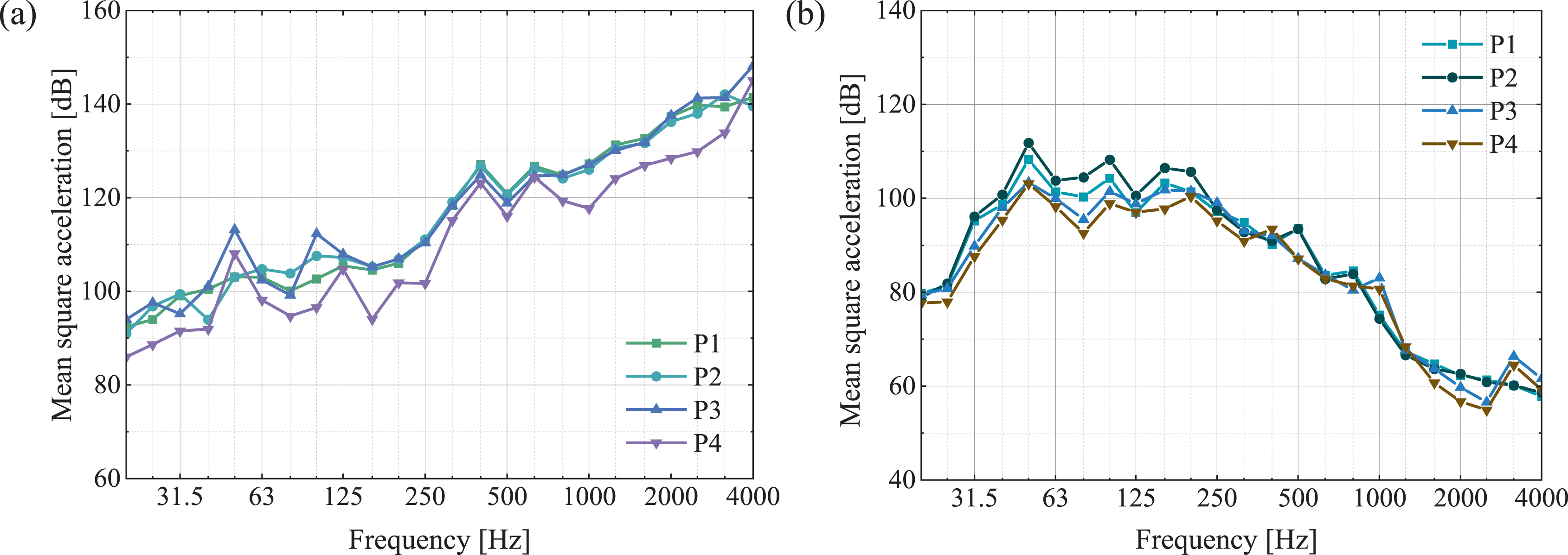
The transient vibration acceleration of the impacted cabin is used as the boundary condition for the time-domain boundary element acoustic calculation, and the radiated sound pressure of the cabin is obtained. Figure 24 shows the time-domain average sound pressure of the four sound pressure measuring points in Cabin 1 and Cabin 2 when the tapping machine is located at P1–P4, respectively. It can be observed that the trend in sound pressure change is consistent with that of vibration. The time-domain average sound pressure of four microphones in the receiving cabins (a) Cabin 1; (b) Cabin 2.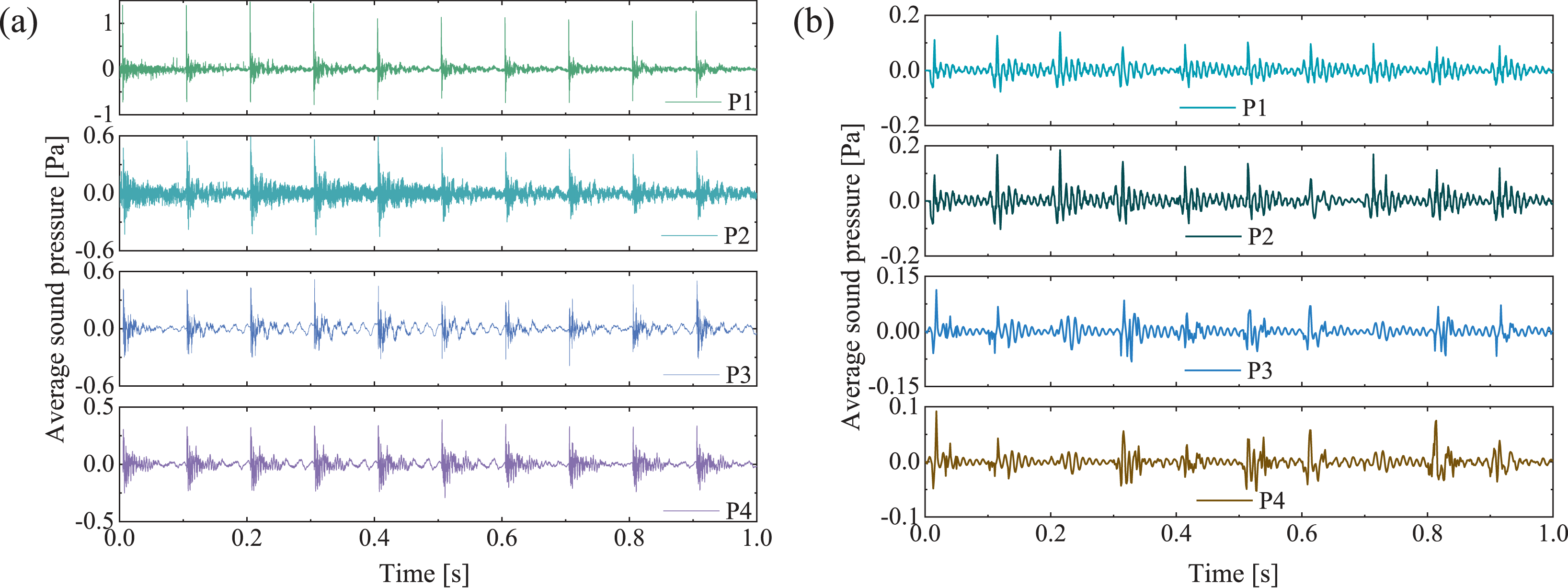
The energy average sound pressure level in the receiving room needs to be combined with the results of the sound pressure measuring points in the corner and center of the receiving room. When the ISO tapping machine is located at different positions P1–P4, the energy average sound pressure levels of the receiving room are 
The results of (a) One-third octave 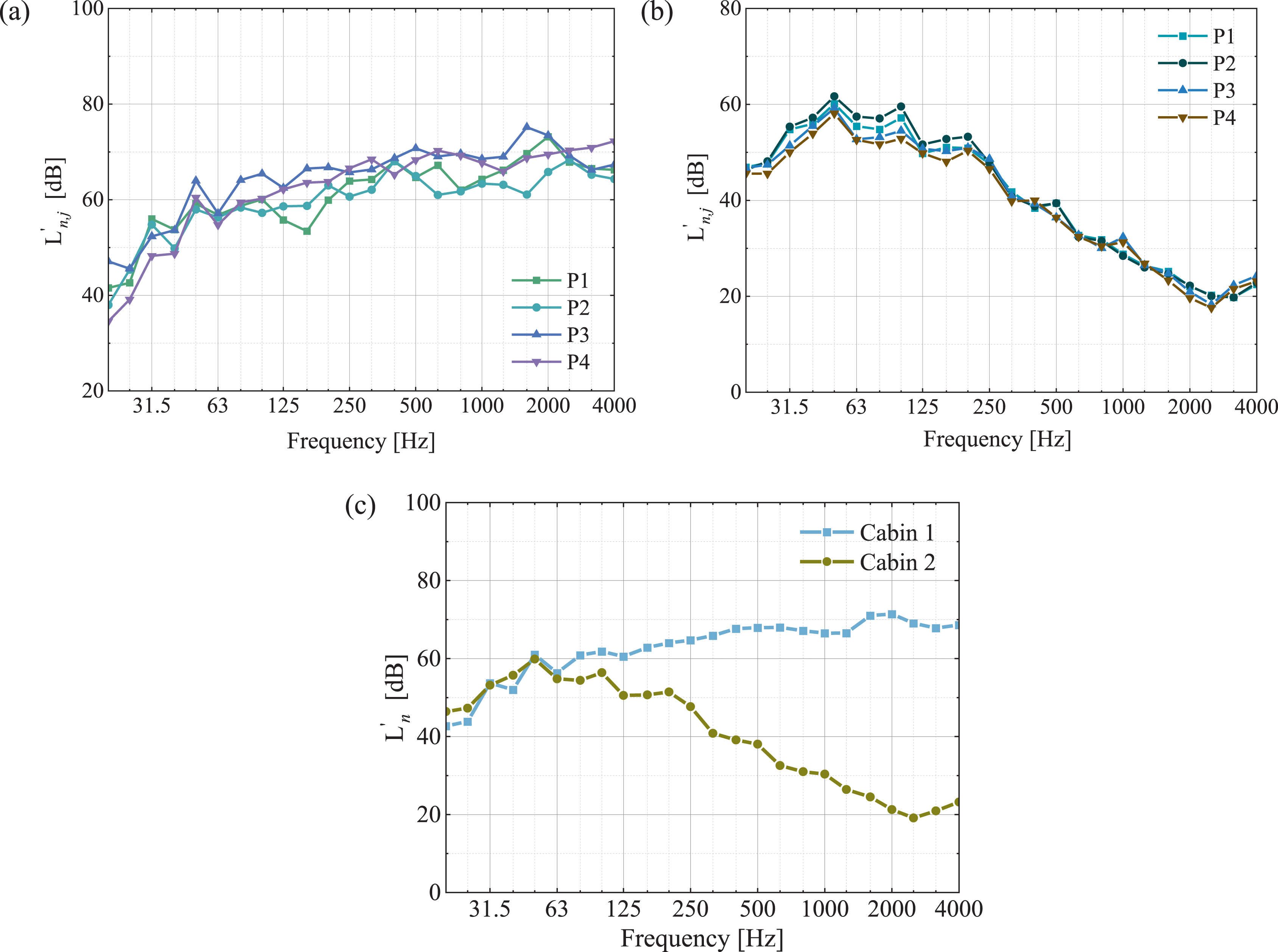
Model experiment
An experimental test of transient vibration and noise in cruise cabins was conducted to verify the accuracy and effectiveness of the numerical analysis. During the test, the passenger ship was docked at the pier with auxiliary equipment, air conditioning, and ventilation in operation. Deck 11 and Deck 12 were selected for the experimental tests, consistent with the numerical analysis.
Experimental test instruments
The transient impact vibration and noise in cruise cabins were tested according to the ISO 16,283-2 standard. 50 The test equipment used included an ISO tapping machine (TM004), four microphones (MPA471S), brackets, three accelerometers (PCB-1A803 E), and a data acquisition system (NI-9237). The microphones were mounted on the bracket, and the data acquisition system was connected to a computer.
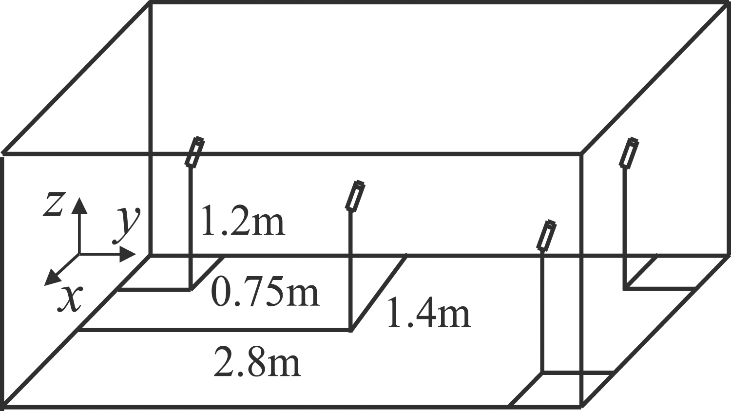
An ISO tapping machine was used as the impact source, and tests were conducted separately for the two cabins with rigid (at Deck 11) and carpet-covered floors (at Deck 12), as shown in Figure 26. The impact source room was the cabin with the ISO tapping machine, while the cabin directly below served as the receiving room. The ISO tapping machine was positioned at a 45° angle to the beam direction and was at least 0.7 m away from the sidewalls. The blue points in Figure 11 represent vibration measurement points #1–#3, and the impact positions were P1–P4. The low-frequency energy average sound pressure level in the receiving room was a combination of the sound pressure level measurement points from the corner and center microphones. The impact sound pressure level was measured by four microphones, all located at a height of 1.2 m. The three corner microphones were 0.75 m away from the sidewalls, as shown in Figure 19. All measuring points in the test were consistent with the numerical model. All tested cabins maintained the same excitation position, and each impact source position was measured at least twice. Measurement setup of experimental tests (a) at deck 12; (b) at deck 11.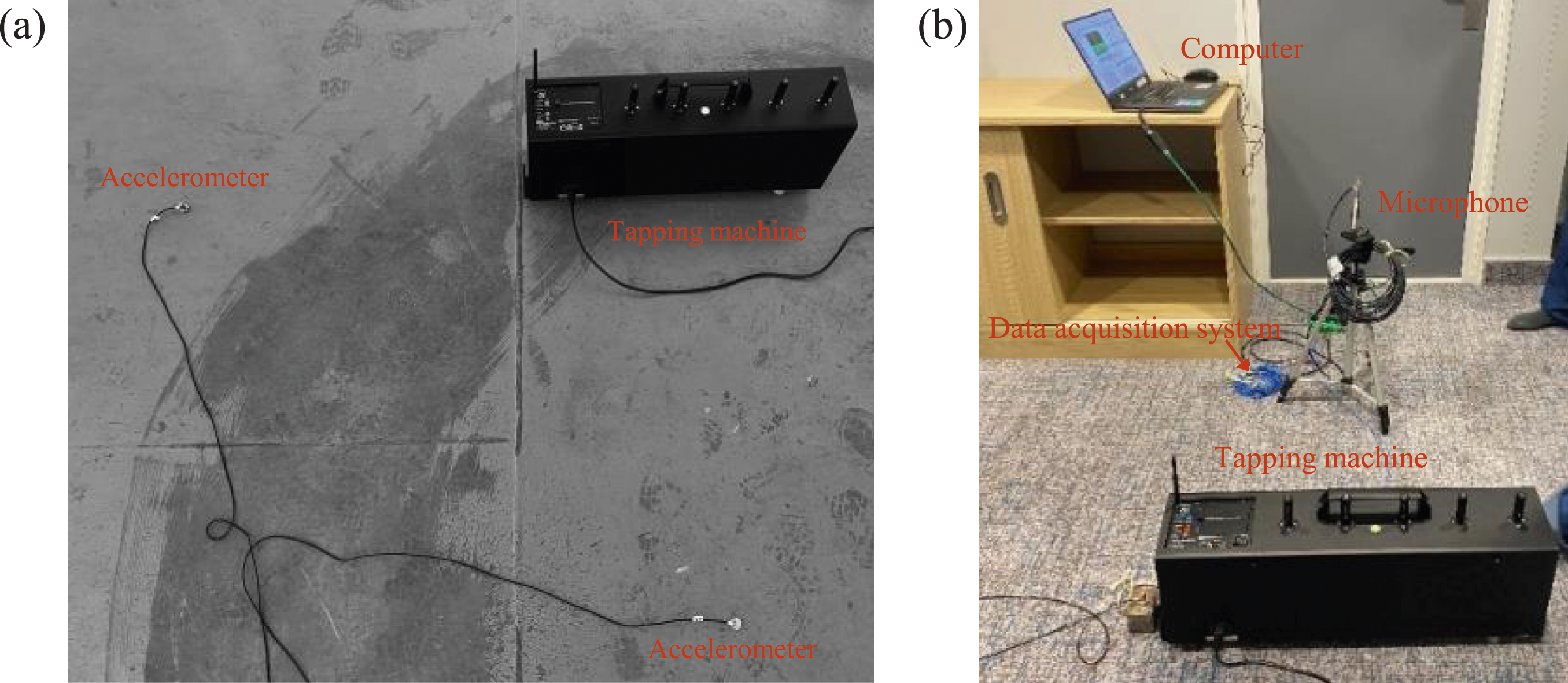
Results comparison
The comparison between the numerical and test results of transient vibration is shown in Figures 27 and 28. The numerical results of the measurement points are in good agreement with the test results. As the frequency increases, the advantage of the 10 Hz multiplier diminishes. This is mainly due to slight deviations in the impact velocity and time history, leading to a shift in the 10 Hz line spectrum. The numerical and test results of vibration acceleration of measurement points of Type A floor with impact position P1 (a) and (c) Time-domain results for #1 and #3; (b) and (d) Frequency-domain results for #1 and #3. The numerical and test results of vibration acceleration of measurement points of Type B floor with impact position P1 (a) and (c) Time-domain results for #1 and #3; (b) and (d) Frequency-domain results for #1 and #3.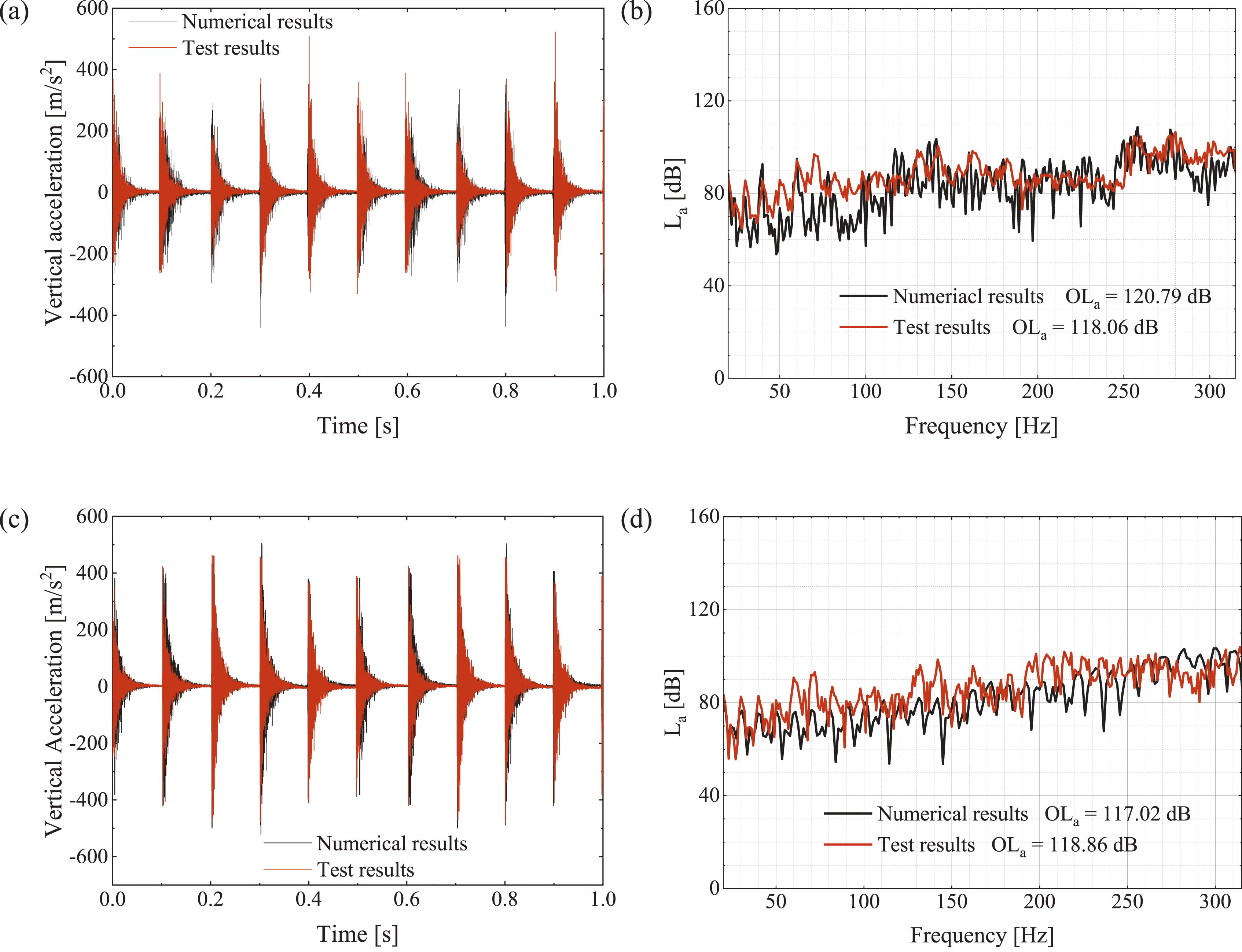
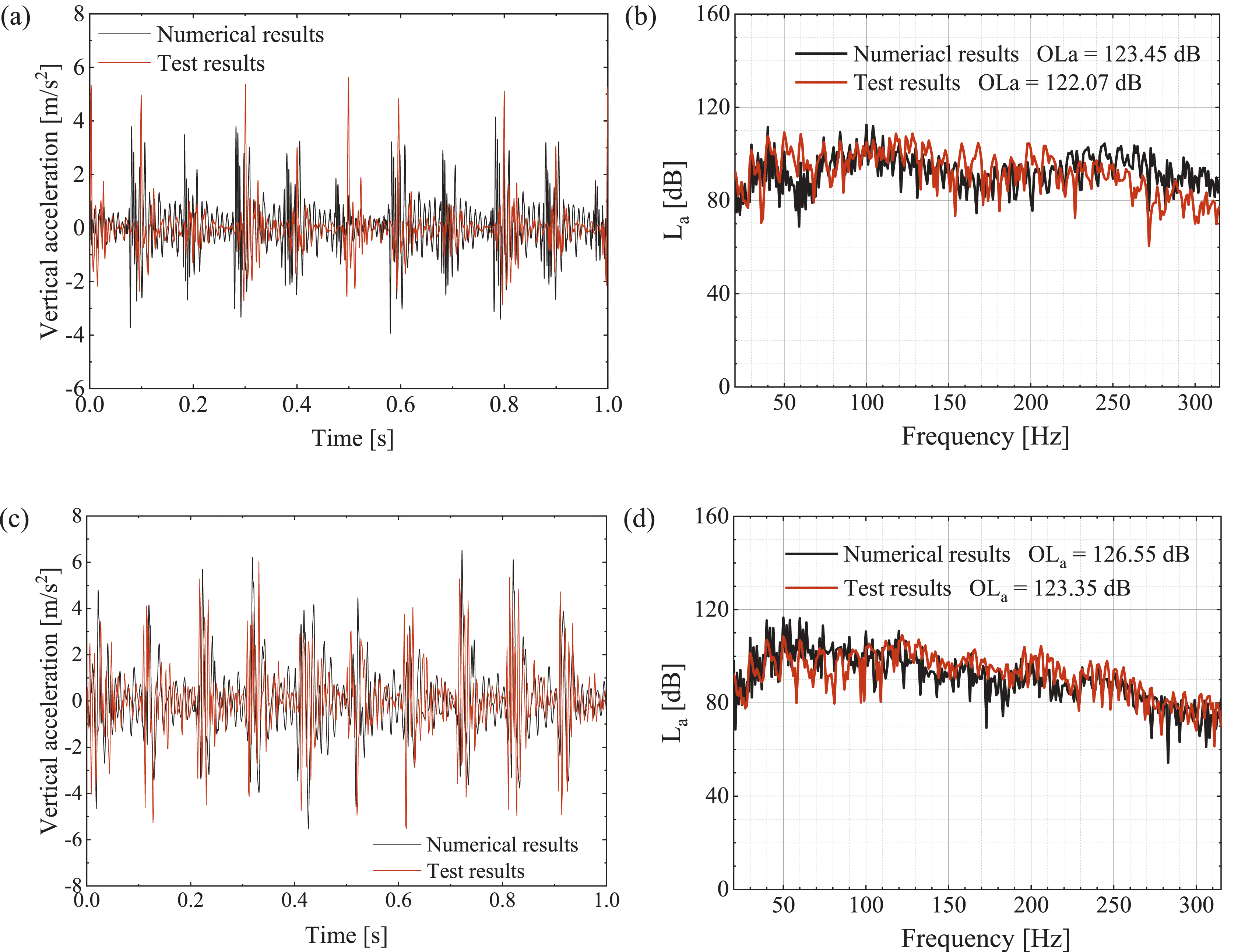
The mean absolute percentage error (MAPE) and the total level error are used to quantify the error between the numerical and the test results in the frequency domain. The MAPEs of
The comparison of the one-third octave normalized sound pressure level The one-third octave normalized sound pressure levels in both cabins (a) Cabin 1; (b) Cabin 2.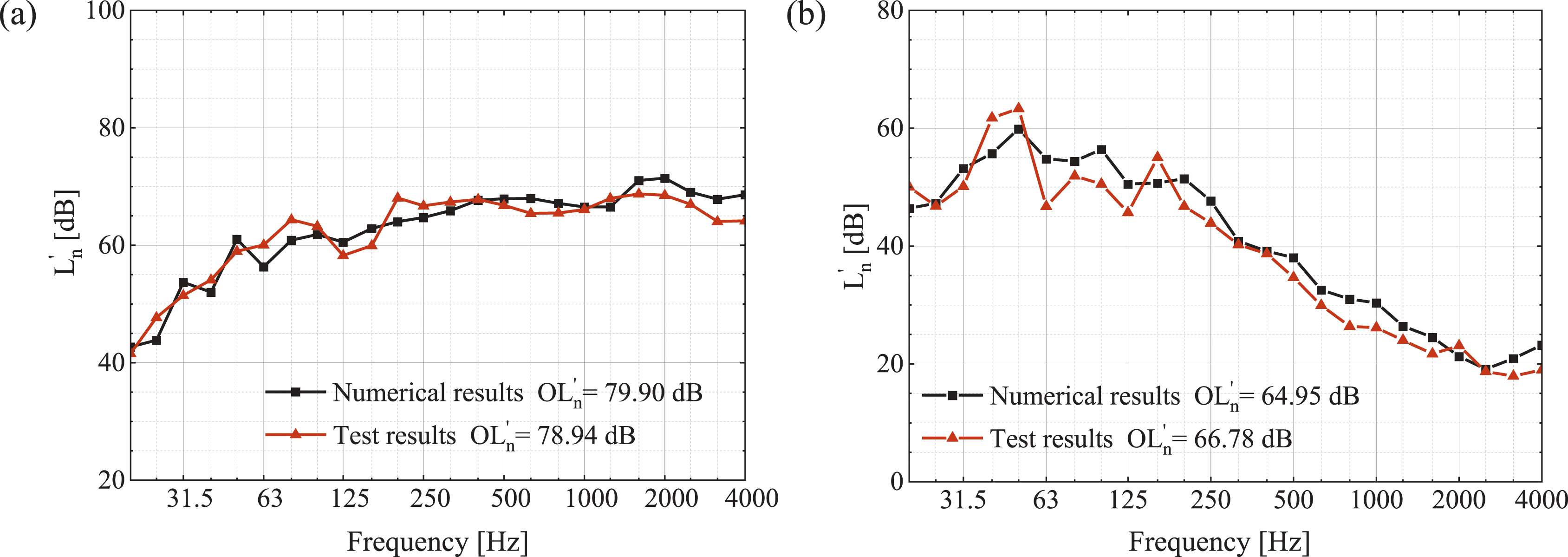
Transient acoustic performance evaluation of cruise cabins
The correspondence between the one-third octave numerical and test results in Figure 29 is further evaluated using other single-number quantities (SNQs). The transient acoustic performance of the cruise cabin is evaluated mainly by the weighted normalized impact sound pressure level
The calculation process of the weighted normalized impact sound pressure level The calculation of 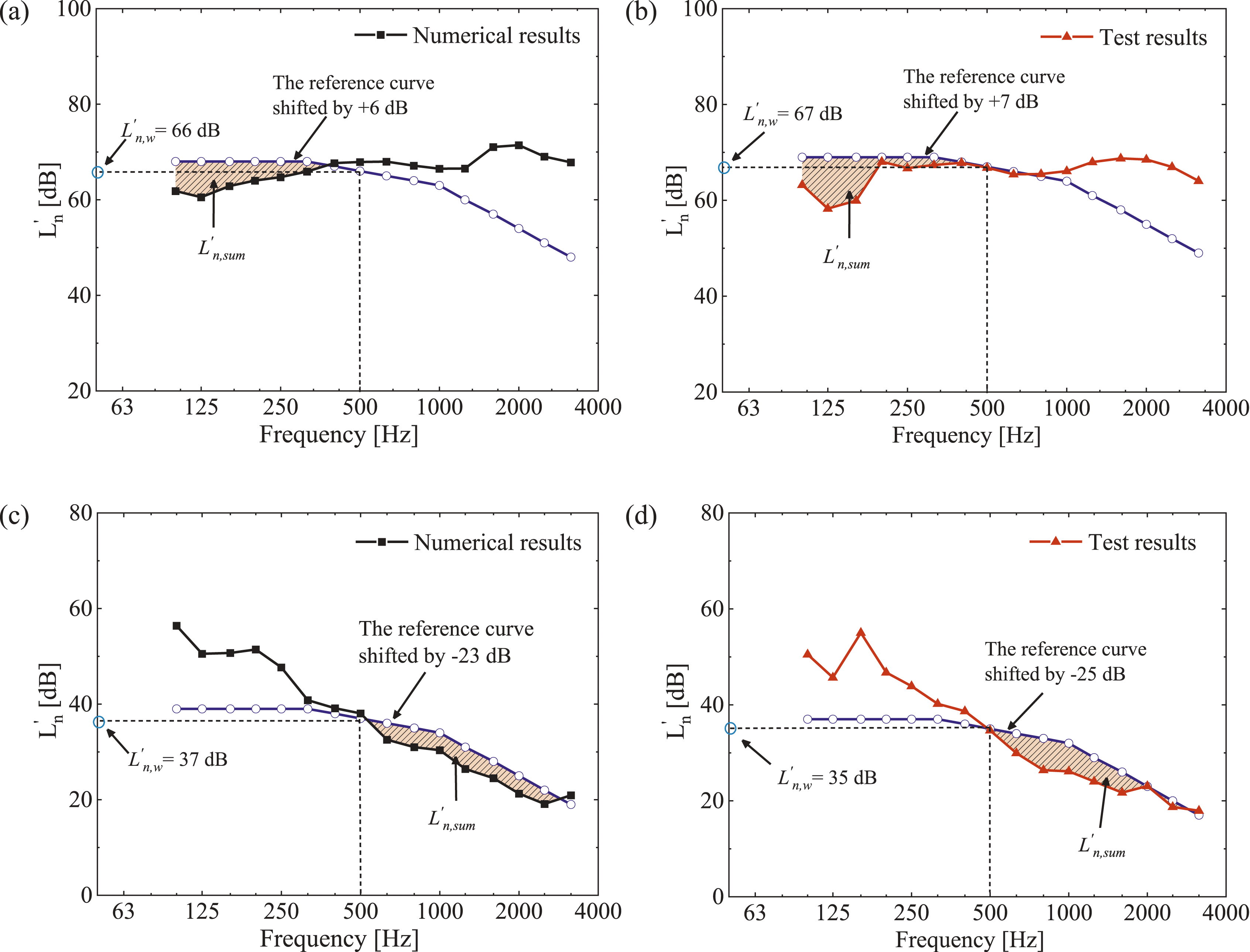
Single-number quantities for transient noise of cabins.
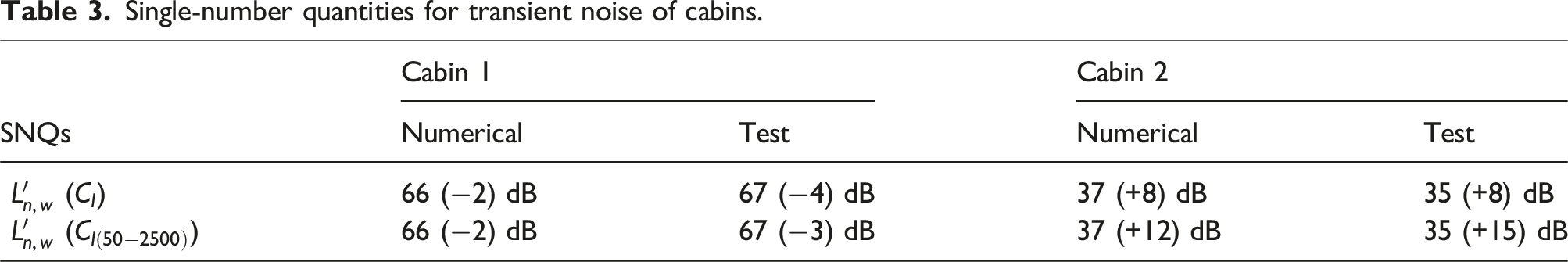
The positive spectrum adaptation term
The numerical and test results of the weighted normalized impact sound pressure level attenuation
Meanwhile, the error of SNQs between the numerical and test results is less than 3 dB, demonstrating a good correspondence between the numerical calculation and the test.
Conclusions
In this paper, a time-domain virtual tapping machine method for predicting and evaluating broadband transient vibration and acoustic performance of cruise cabins is proposed and verified by experimental tests. The main findings of this paper are summarized as follows:
Utilizing the rigid-flexible coupling dynamic numerical model of the virtual tapping machine and the impacted structure, the broadband transient force can be determined, which provides a foundation for evaluating the transient vibration and acoustic performance of cruise cabins.
It is feasible to calculate the broadband transient response of cruise cabins using the TDFEM/BEM combined with the VMSS. The numerical results align well with the test results, with a total level error of transient noise is within 3 dB.
The SNQs proposed in this paper are effective for evaluating the transient acoustic performance of cruise cabins. When the tapping machine acts on the floor with soft coverings and elastic layers, the weighted normalized sound pressure level attenuation in the receiving room is about 30 dB than that of the rigid floor. Soft coverings, such as carpets, can effectively enhance the transient impact acoustic performance, especially in the high-frequency range.
Additionally, the outfitting inside the cabin is simplified when the numerical calculation model is established, and the resulting acoustic differences need further exploration. Furthermore, based on the prediction of transient vibration and noise performance of cruise ships in this paper, the transient noise reduction technology for cruise ships using acoustic metamaterials can be further studied.
Footnotes
Acknowledgments
This study was funded by the Fund of High-tech Ship Research Projects by MIIT. This support is gratefully acknowledged by the authors.
Author contributions
Yingying Zuo: Conceptualization, Validation, Software, Formal analysis, Data processing, Data analysis, Data curation, Writing - Original Draft. Writing - Review & Editing. Deqing Yang: Methodology, Supervision, Experiment Planning, Writing - Review & Editing, Project administration. Jian Xiao: Investigation, Experiment and Data Analysis, Data curation, Formal analysis.
Declaration of conflicting interests
The author(s) declared no potential conflicts of interest with respect to the research, authorship, and/or publication of this article.
Funding
The author(s) received no financial support for the research, authorship, and/or publication of this article.