
Abstract
This paper presents the vibration reduction of lightweight components by adjusting the mechanical properties of their boundary conditions in vibration test rigs. The variable boundary conditions are achieved by adjustable impedance elements, which are mechanical elements that can change their stiffness and damping behavior separately and are designed for use in vibration testing. A new generation of an adjustable impedance element is presented in this publication and its use in a large component test environment. The influence of the adjustable mechanical properties of the interfaces on an aircraft partition is shown. A holistic finite element model is presented to predict the interactions between the adjustable interfaces and the test object. A vibration reduction of about 65% compared to current rigidly designed joints is achieved. The influence of vibration on the partition is investigated experimentally for different stiffness and damping ranges and the corresponding simulation model is validated.
Keywords
Introduction
The vibration behavior of all types of structures is influenced by their mechanical boundary conditions. In dynamic testing, the interfaces are generally designed in such a way that they have as little influence as possible on the vibration behavior 1 or, if they are known, they can be calculated and be eliminated. However, the influence of the interface properties, which is to be avoided in most dynamic investigations, can also be used positively to achieve a targeted vibration reduction.
In virtual models, adjustments to interface properties can be implemented efficiently. However, in physical investigations, there is a lack of available options for adjusting the interface properties. In order to map compliant interfaces, individual interface elements must be developed for each characteristic. 2 Furthermore, their dynamic properties must be validated in physical tests, as damping behavior of joints is difficult to predict. 3 Interface elements with adjustable properties that meet the requirements of test engineering could represent compliant boundary conditions for a variety of vibration tests. Such elements would contribute to the efficient testing of products on vibration test benches.
Different publications address the possibility to change the vibration behavior by changing the properties at the interface. Gaul et al. 4 investigate the vibration reduction on a beam by the defined pressing of a plate by using a piezo element. Santos, Enemark, Alves, Guimarães et al.5–8 investigate the vibration behavior of motor shafts, depending on different bearing stiffnesses. Liu et al. 9 show the influence of magnetorheological dampers in different floors on an elastic framework. Deng et al., Sebesta et al., Zhang et al.10–12 use adjustable dampers in seat suspensions.
Elements with compliant properties are commonly studied in the literature. Reviews by van Ham, Tagliamonte, Vanderborght, Lavate and Wolf et al.13–17 summarize these stands well. Their work is mainly focused on the application in robotics. The large number of elements are designed for explicit applications and are often not widely applicable. 18 Accordingly, they do not satisfy the broad fields of application of experimental testing, with their requirements of vibration resistance, high strength, widely adjustable and dominantly symmetrical mechanical behavior, reliability and accuracy. 19 Few studies in the literature present test results across a range of frequencies. Noteworthy examples include the works of Enemark et al. 6 and Maciejewski et al., 20 which provide valuable insights in this area. Additionally, the investigation of physical elements with independently adjustable stiffness and damping properties is quite rare. Notable contributions in this domain are the publications by Catalano et al. 21 and Enoch et al., 22 which introduce elements featuring distinct mechanisms for adjusting stiffness and damping separately.
Millitzer et al. 2 develop translatory connections with adjustable stiffness, which are intended to simulate boundary conditions in test rigs. They aim to represent real environmental structures efficiently, whereas this work focuses on the holistic development of the product and their interfaces.
In the current state of the art, there are only a few studies that deal with the systematic vibration reduction through adjustment of interface properties across broad operational ranges. In addition, it is missing interface elements that can vary both stiffness and damping properties, and more importantly, elements that are characterized over the necessary wide range of applications for the use as interfaces on vibration test benches.
To enable vibration testing with adjustable interfaces in physical experiments, compliant interface elements have to be developed. Adjustable impedance elements are machine elements with adjustable properties developed for investigations of joint properties in vibration testing. 23 These elements consist of a separately adjustable stiffness mechanism and an adjustable damping mechanism. 23 By systematically varying the properties of the adjustable impedance elements, the vibration behavior of the holistic system consisting of the test specimen and the interface elements can be affected.
A challenge in the dynamic investigation of a holistic system lies in the interaction of various constituent subsystems.24,25 By adjusting the properties of the components, the resonance can be reduced or, in the worst case, exacerbated. 26 To avoid overloading that could lead to failure, it is necessary to establish a model before developing the interface elements to derive the resulting mechanical characteristics from it. 27
The contribution of this publication has two objectives. First, to present a suitable adjustable impedance element with separately adjustable stiffness and damping characteristics for vibration testing. Secondly, to show the potential of vibration reduction on lightweight structures. As a representative application, the vibration study is implemented on an aircraft partition.
Materials and methods
The aim of this work is to achieve a vibration reduction of the partition. This requires a definition of the vibration excitation in the test environment, a model of the dynamic behavior to achieve the optimal interface properties, the development of an element to represent these, and the validation test.
Initial situation at the test environment
Structures from the aircraft cabin, such as galleys, partitions, lavatories or overhead bins, are subjected to dynamic loads. Windmilling is a safety-related event in the design of cabin elements. In this case, the engine blades become detached during flight. The switched-off engine continues to be driven by the airflow during the remaining flight time, and the resulting imbalance generates a vibration. 28 This leads to an externally excited vibration of the aircraft structure and the cabin interior. For this reason, the structures must be certified against these loads. 29 For this purpose, the structures must be examined in the low frequency range with different acceleration amplitudes.
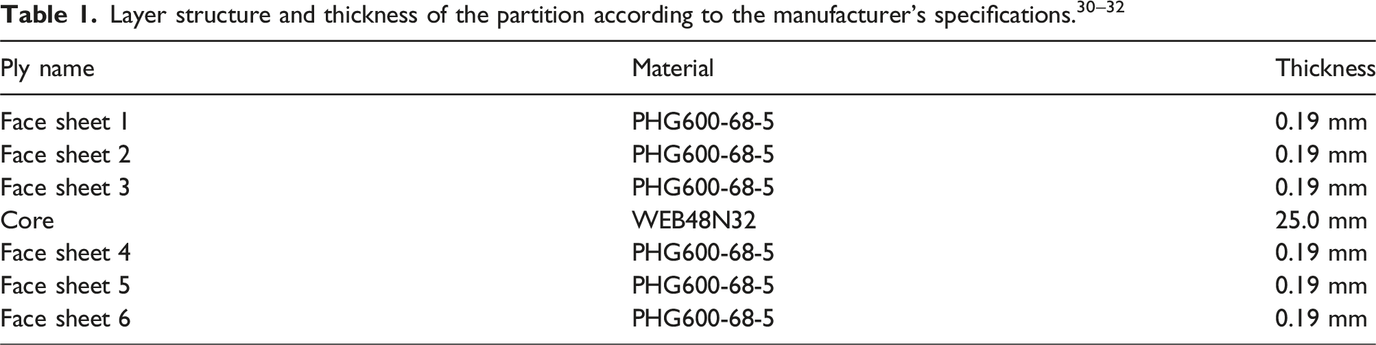
This publication focuses on the study of an aircraft partition under vibration loading. Figure 1(a) shows the partition on the vibration test rig at the Hamburg University of Technology (TUHH). In this hydraulic test rig, a ring platform is moved via six double-acting cylinders. The yellow ring platform and the aluminum frame behind it are excited together to excite the partition in the x-direction. The structure under test is an original partition (Partition Typ 1, Albert Mühlenberg Apparatebau GmbH & Co. KG, Gauting, Germany) of the Airbus A320 family. The partition has a size of 2054 mm × 1353 mm and thickness of 26.2 mm. The laminate configuration is shown in Table 1. The partition consists of two outer planes, each with 3 layers laminate of glass fiber reinforced polymers (GFRP),30,31 and an aramid honeycomb core.
32
The weight of the layer structure is 10.8 kg. It is provided with edge protection on the outer side and has 77 inserts for attaching add-on elements and connections. The partition has a total mass of 15.7 kg. Partition at the hexapod vibration test bench in (a) with proposed adjustable properties at the interface and in (b) with places sensors for acceleration, force and displacement.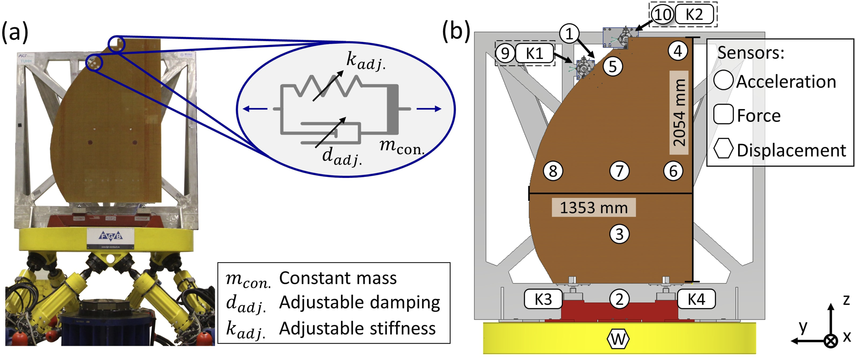
In the initial situation with rigid connections, all four interfaces are provided with original interfaces from the A320. Both upper connections of a partition to the outer aircraft structure are via rods and are therefore rigid in the x-direction and free for the y- and z-directions. The lower connections to the floor structure are via joints which are inserted into the seat rails and are therefore translationally rigid and free in rotation. In the second step for the vibration reduction, the two upper interfaces are implemented with adjustable impedance elements. This makes them compliant in x-direction with adjustable stiffness and damping.
Figure 1(b) shows the placement of the sensors for acceleration (3D 500 g TLD356A02, PCB Piezotronics Inc., Depew NY, USA), force (S9M/10 kN, Hottinger Brüel and Kjaer (HBM) GmbH, Darmstadt, Germany) and displacement of the test rig itself. The data acquisition of all sensors is done via the HBM QuantumX system. The measurement signals are recorded at 1200 Hz in NI Diadem 2019 (National Instruments Corp., Austin, USA) and the data processing in Matlab 2022b (The MathWorks Inc., California, USA).
When performing the test, the vibration is increased with a sinusoidal signal from 3 to 23 Hz with a constant peak acceleration a
in
= a2 = 2.5 m/s2 at a rate of 0.1 Hz/s. The amplification is then calculated by the Fourier-transformed ratio of the sensor at the partition to the peak amplitude of the input signal (see Equation (1)).
Figure 2 shows the amplifications HI6,2 and HI8,2 for the two mainly affected sensors by the two resonances of the partition. The bending shape of the first resonance at 12.3 Hz is particularly pronounced at sensor 6. A high amplification of 69.3 with a pronounced phase change of −π is observed. The second resonance is formed at 21.4 Hz. This is also a bending shape in which the two sides of the partition oscillate in an antiphase around a neutral centerline. The amplification of 52.5 is more pronounced at sensor 8 with a change of the phase of −π. Comparison of the amplification from sensor 2 at the test rig to sensor 6 and 8 at the partition, results shown for the experiment and the simulation model to determine the structural damping, (a) shows the absolute value and (b) the phase of the amplification.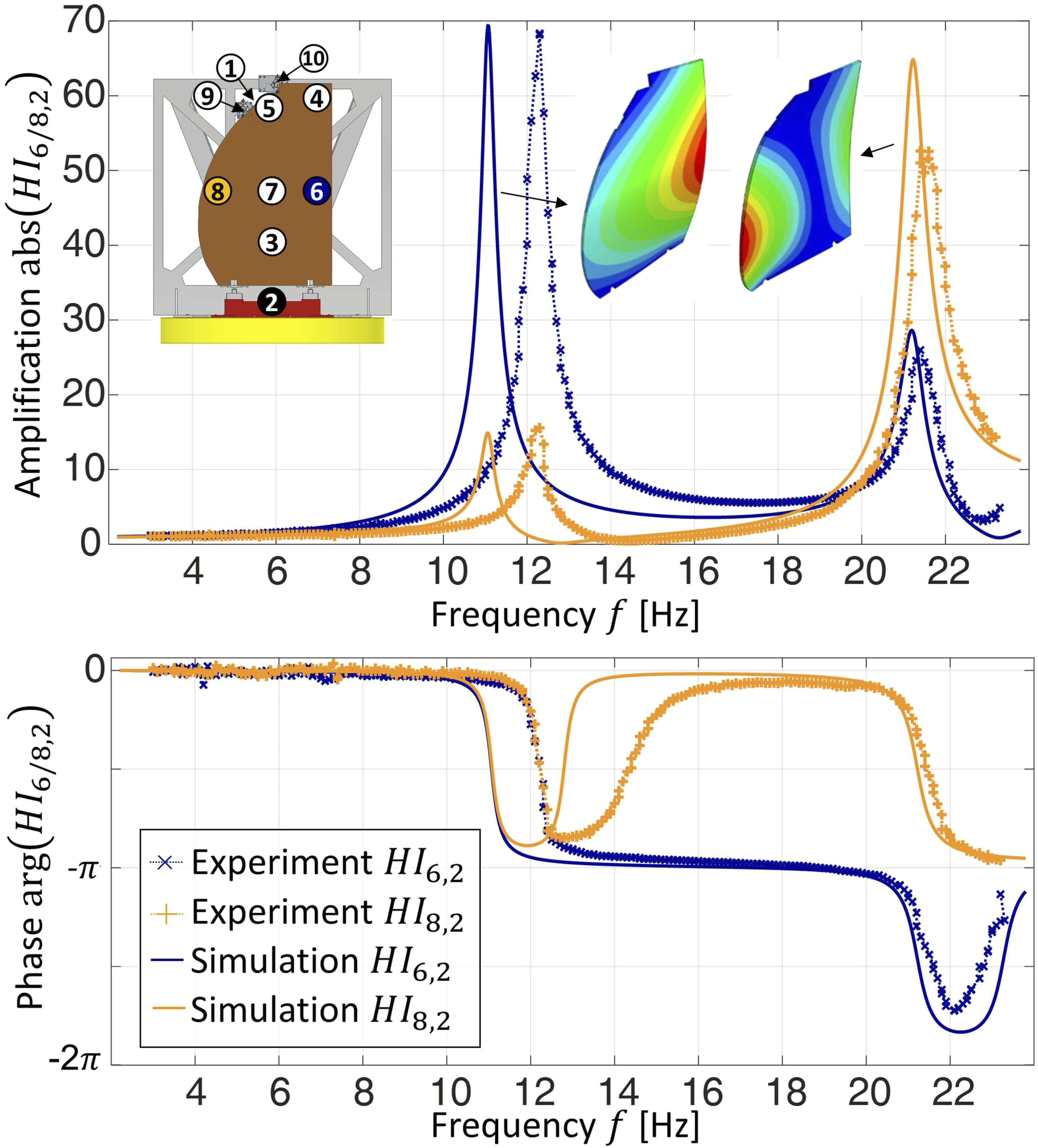
Model of the partition
The finite element method (FEM) can be used to implement complex geometries, combined load cases, changing boundary conditions, and different material laws.
33
The fundamental differential equations of elastodynamics are described by the mass matrix 
The simulation is performed in Abaqus 2021 (Dassault Systèmes, Vélizy-Villacoublay, France) as a modal dynamics analysis in the frequency domain. The partition is abstracted in this work using rectangular shell elements, where each node represents three translational and rotational movements, as shown in Figure 3(d). Orthotropic behavior with three-dimensional engineering constants is assumed in the purely elastic range, according to the manufacturer’s specifications.30–32 The used mesh size is 10 mm × 10 mm for the partition. Physical test setup of the connections and their numerical implementation,
27
(a) and (c) showing the upper attachment at sensor K1, (b) and (d) showing the lower attachment at sensor K4.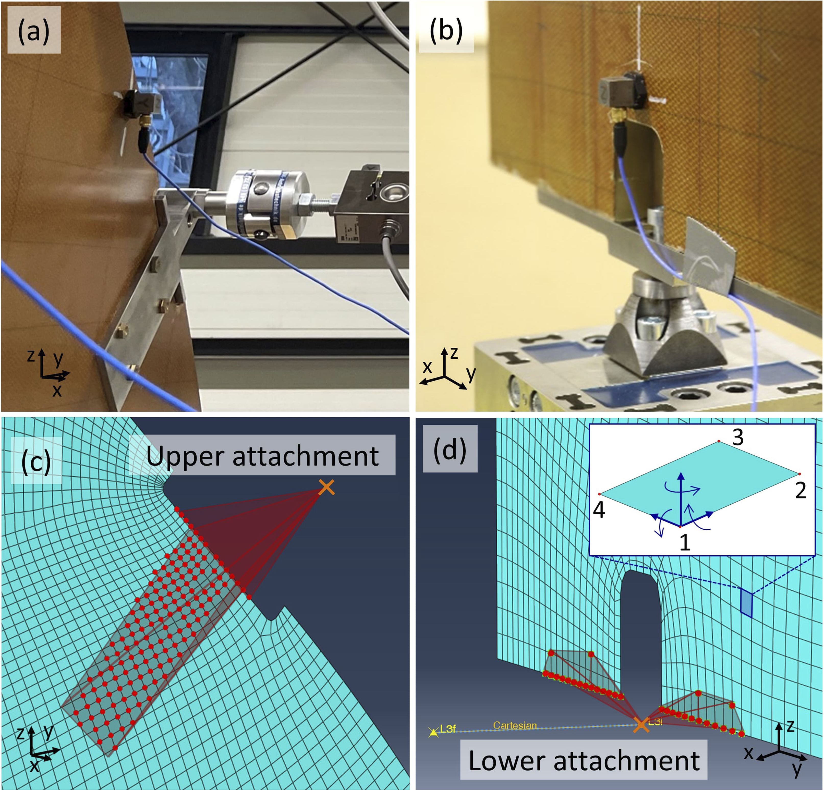
The mounts to which the partition wall is connected are modeled with rigid connections to the pivot points of the joints, as shown in Figure 3. The joints are modeled as moment-free. The lower bearings are translationally fixed, the upper ones are just fixed in x-direction.
Using structural damping, the damping matrix is represented by a complex stiffness matrix
34
(see Equation (3)). Therefore, the damping is proportional to the displacement.
34
Structural damping is suited for dynamic analysis in the frequency domain and can be used here for displacement and velocity around 90° phase shift.
35

In order to compare the simulation model with the experimental data in terms of damping, the structural damping of the simulation model is adjusted so that the amplification at the resonances is comparable. For this purpose, the structural damping in the initial model is adjusted iteratively until the amplification of the model corresponds to that of the experiment. For the investigated partition, this results in a structural damping value of s = 0.029, which remains constant for further adjustments of the interface properties. The resulting simulated response function is plotted in Figure 2 compared to the experimentally determined one. Overall, there is a good agreement between the simulated and experimental response functions. Only the first resonance frequencies differ slightly from each other.
Optimization of the vibration response
In this step, the model is expanded with parametric interface properties to determine the resulting vibration behavior of the partition. For this purpose, a parametric connection is established between the upper joint points and the excitation.
Figure 4(a) compares three amplifications with different interface stiffnesses and dampings to the rigid connections. In this application, only the two upper interfaces are varied, and both of them have the same values for stiffness and damping. The two lower interfaces remain rigid. The maximum amplification for each set of interface parameters is documented. Figure 4(b) displays the amplification over an entire map of interface properties. (a) Simulated amplification of the partition over frequency with different interface properties and (b) curve of all maximum values of the amplifications over stiffness and damping properties.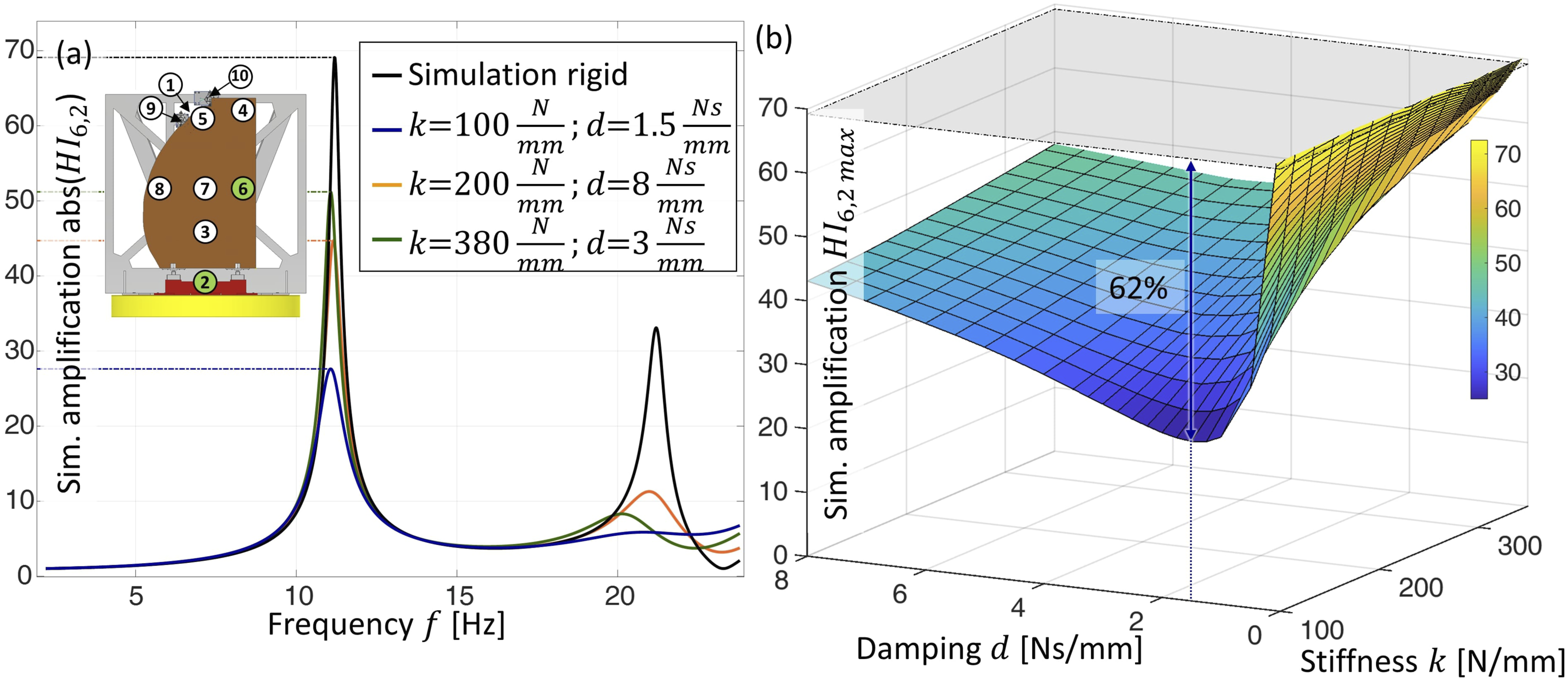
The lowest amplification of the partition is reached at k = 100 N/mm and d = 1.5 Ns/mm, with an amplification of HI Sim;6,2 = 27, resulting in a vibration reduction of 62% at point 6.
To develop compliant interfaces with these optimal interface properties, their loads and displacements must be determined. Figure 5(a) shows the resulting force at the two joints J1 and J2. On the one hand, the joints must be designed to carry the maximum load of 180 N. On the other hand, they must reach the minimum force in the resonance range in order to overcome the friction of the element. A transmitted force below the static friction prevents a compliant movement at the interface. The minimum occurring force of the simulation model is determined in the range of ±0.5 Hz around the resonance. In this case, a minimum force at the joint J2 of 45 N is derived. Comparison of the simulated force and displacement at the upper joint J1 and J2 for rigid connection and compliant properties.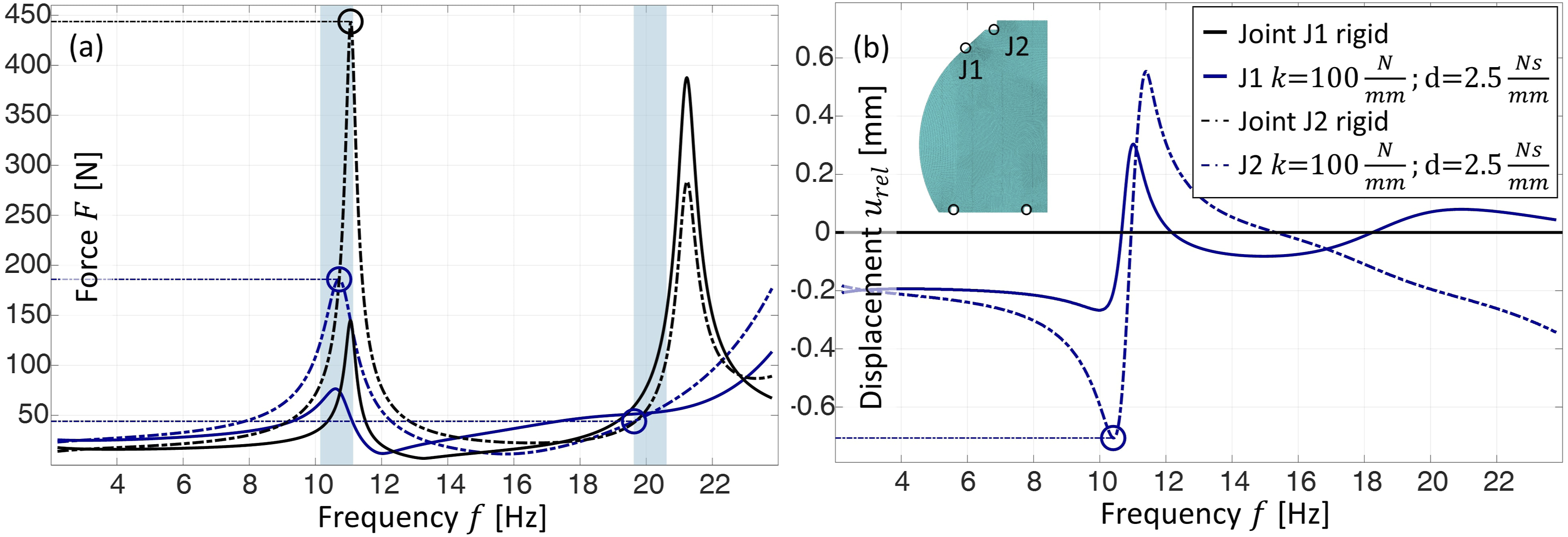
Compared to the interface forces to be transmitted with rigid connections, these are reduced by the compliance at the interface. This also represents a potential for lowering interface loads in the aircraft.
Figure 5(b) shows the relative displacement of the compliant joints, the adjustable impedance elements to be developed must allow this displacement of 0.7 mm.
Design of the adjustable impedance element
In developing the adjustable impedance element, it is possible to build on previous experience in developing a stiffness element and a damping element.
A promising principle to achieve adjustable stiffness is the use of two antagonistically preloaded progressive springs.36–38 In order to achieve an adjustable stiffness without a preload force being effective, the two progressive springs must be tensioned antagonistically against each other so that the preloads equalize. Figure 6(a) shows the schematic structure of an antagonistic arrangement with two quadratic rising characteristic springs. The adjustable stiffness of the system results to linear spring force k
adj,
in equation (4). The design has been proven its use as an adjustable stiffness element in Lindenmann et al.
39

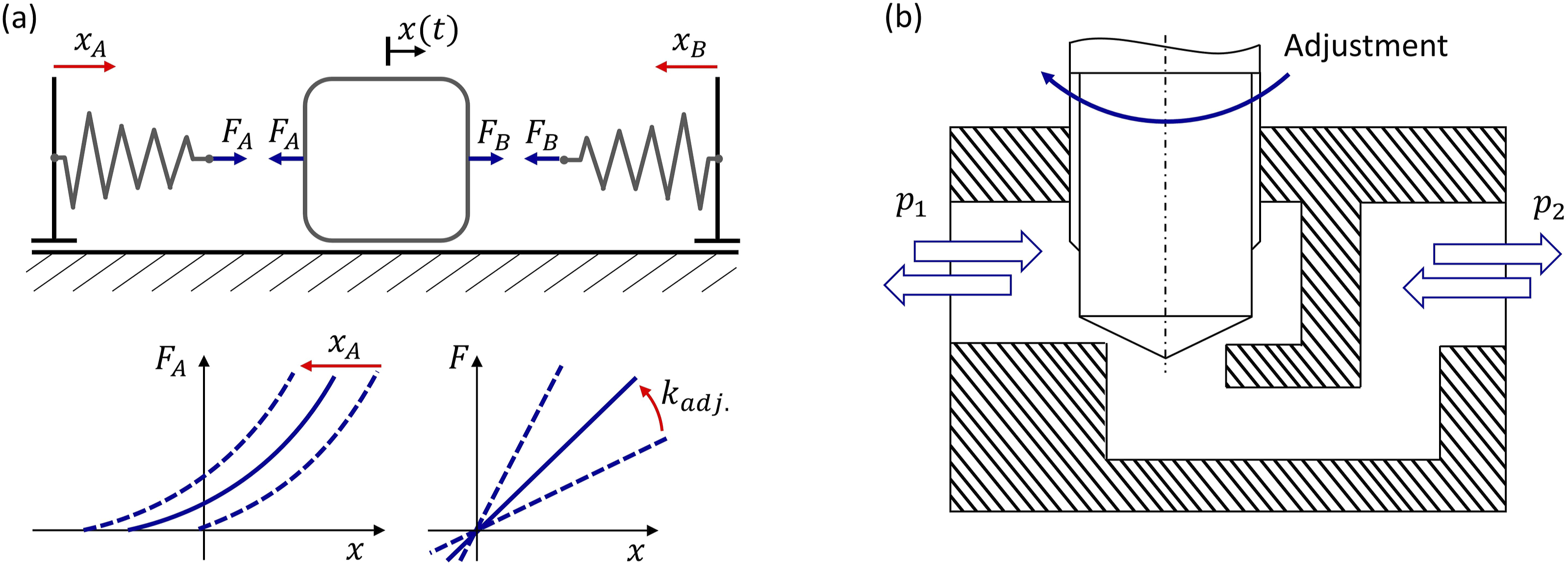
For the adjustable damping, hydraulic dampers by restriction of the fluid flow can be used.40–42 The first additive manufactured hydraulic damper is published in Ref. 19, and insights from optimizing fluid flow to limit fluid heating can be applied. The restriction function in hydraulic dampers is achieved by geometric narrowing the flow at a restriction valve, in this area the energy dissipation is occurring. 43 Figure 6(b) shows the typical structure of a restriction valve. Depending on the flow velocity, geometry, and fluid properties a superimposed laminar and turbulent flow is resulting. 15
Requirements and concept
The adjustable impedance element has to fulfill the requirements regarding stiffness, damping, load and displacement. To map the upper rods, it needs a translational degree of freedom with adjustable stiffness and adjustable damping. Furthermore, the available installation space between the test assembly and the partition must be sufficient, for which a length of 420 mm is available. The adjustable impedance element shall be vibration resistant from 3 to 23 Hz.
Due to the limited installation space, a compact solution should be aimed for. The antagonistically preloaded springs and the lines for fluid guidance lead to a high space demand. To achieve a compact design, the springs are in the hydraulic volume of the damper, as shown in Figure 7. The two antagonistically arranged springs are preloaded by adjusting nuts on the piston axis. Schematic of the adjustable impedance element showing the separately adjustable stiffness principle and damping principle.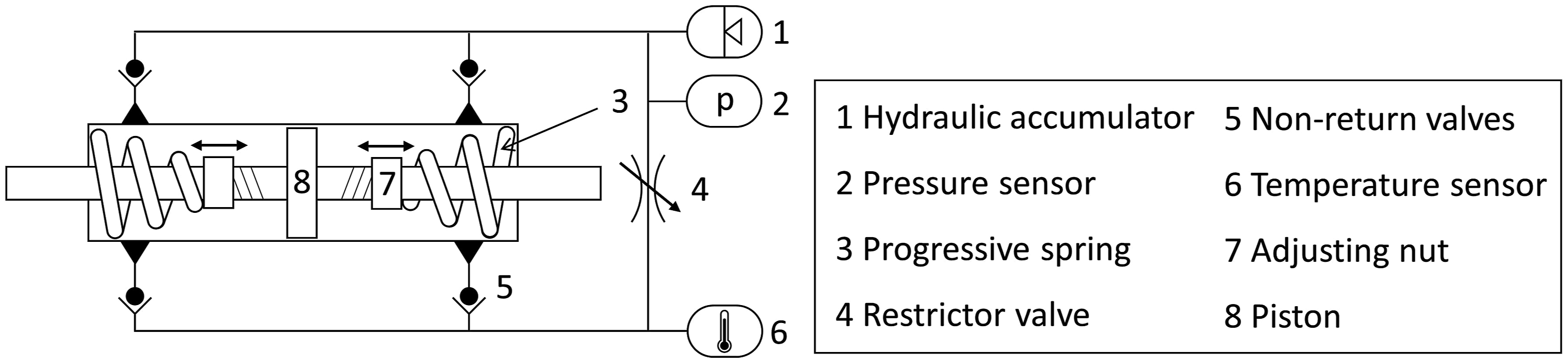
The synchronous damper with its piston is connected to the four non-return valves. The resulting rectifier circuit feeds the hydraulic oil symmetrically to the restrictor valve, resulting in symmetrical mechanical behavior of the element. Furthermore, the restrictor valve is always supplied with hydraulic oil from the oil chambers, which ensures good circulation of the fluid. The hydraulic accumulator keeps the pressure constant and the pressure and temperature can be monitored via the sensors (detailed in Ref. 19).
Detailed design
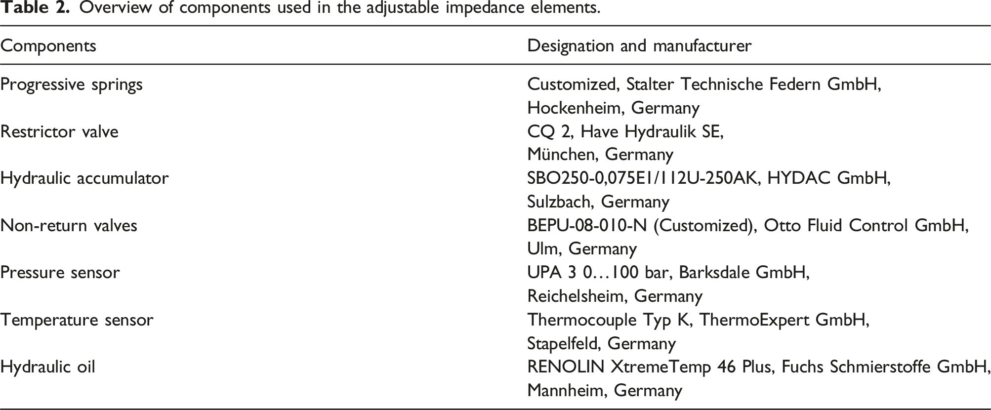
Overview of components used in the adjustable impedance elements.
The housing of the hydraulic system is conventionally made of stainless steel. The piston is located in the center of the housing and made of high-strength steel. The pipes to the restrictor valve are routed through a system made using additive manufacturing. The function-oriented design strategy of Klahn et al.
45
is applied to achieve an optimized additively manufactured system. Figure 8 shows the resulting pipe system in which the restrictor valve and non-return valves are integrated. Design of the adjustable impedance element with the additive manufactured valve block, red lines mark the fluid flow and black lines the adjustment of the stiffness mechanism.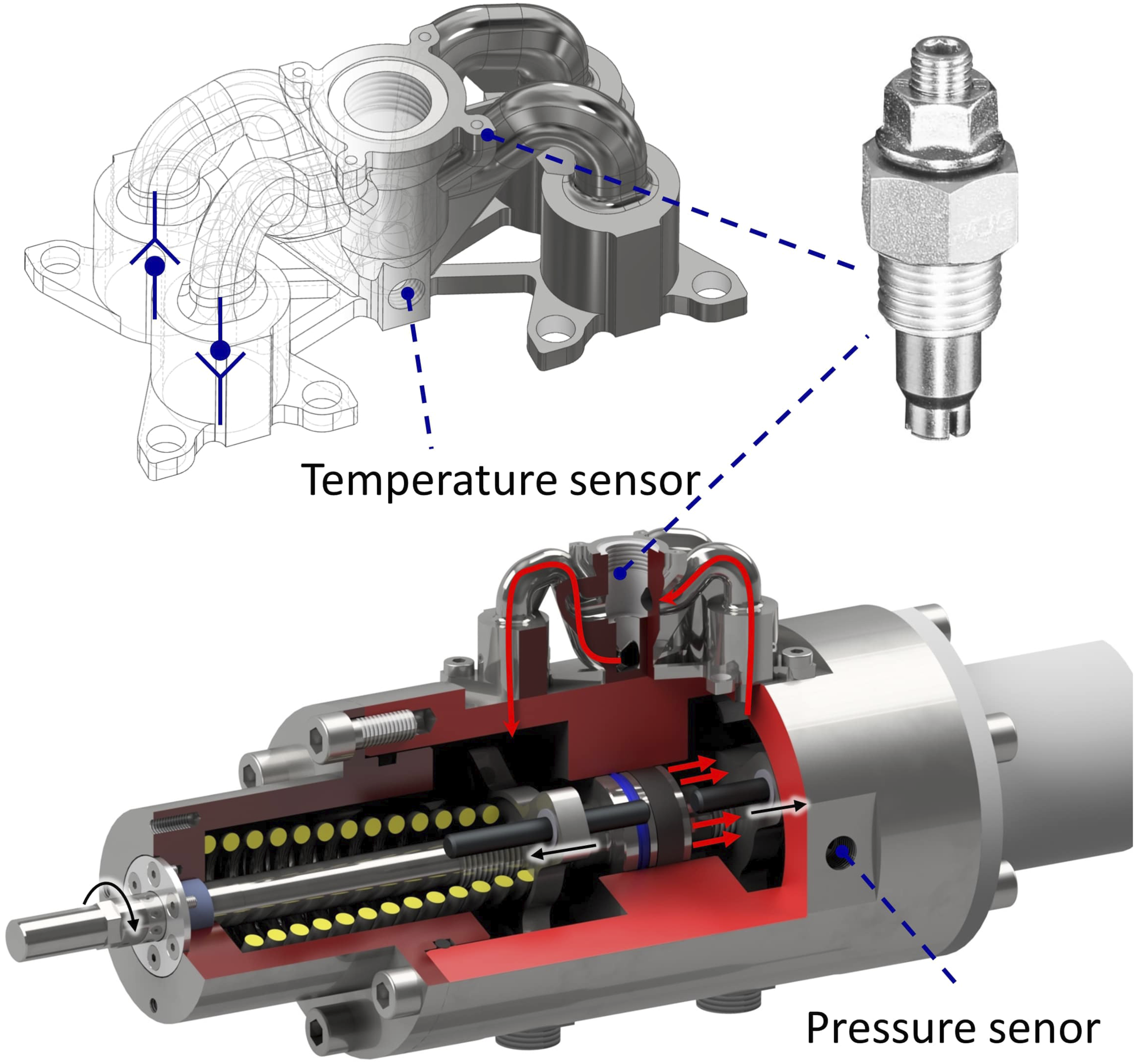
When the piston is loaded, the hydraulic oil is directed to the restrictor valve as shown with the red arrows in Figure 8. The adjustment of the damping is varied by the turns of the restrictor valve.
The antagonistic springs are located centrally in the housing and are supported on the housing cover. The load is transferred from the axis to the springs via the adjusting nuts. By rotating the axle, the two adjusting nuts move outwards on a left-hand and a right-hand thread. In this way, they increase the preload of the springs and thus the stiffness.
The system is filled with hydraulic oil and preloaded to a pressure of 10 bar. The pressure must be higher than the vapor pressure to prevent the oil from evaporating and cavitating. 46 This makes it ready for further investigation and use in test environments.
Test results
To determine the element’s properties, it is tested on a servo hydraulic test rig. The test procedure is performed according to Ref. 47. The elements are fixed on the housing side and the axis is moved with a frequency from 1.5 to 23.5 Hz at a peak amplitude of displacement of 1 mm. The acceleration (3D 50 g 356A15, PCB Piezotronics Inc, USA) and force (S9M/10 kN, Hottinger Brüel and Kjaer GmbH, Germany) are recorded and the apparent stiffness and mechanical impedance are determined via these.
Figure 9(a) shows the resulting apparent stiffness (AS) calculated using the Fourier-transformed force signal divided by the displacement signal. With the restrictor valve open, the resulting values are recorded at different rotations of the axis. In the lower frequency range, this signal converges to the stiffness. For the frequency range from 1.5 to 4.5 Hz, the mean value and the standard deviation are determined for each setting. From this, the curve of the stiffness in Figure 9(c) is derived. The average stiffness can be adjusted from k(a
K
= 4) = 110 N/mm to k(a
K
= 16) = 350 N/mm. Test results of the adjustable impedance element, (a) showing the apparent stiffness (AS) and (b) the mechanical impedance (MI) of the element, (c) is showing the approximation of the resulting stiffness, and (d) damping behavior.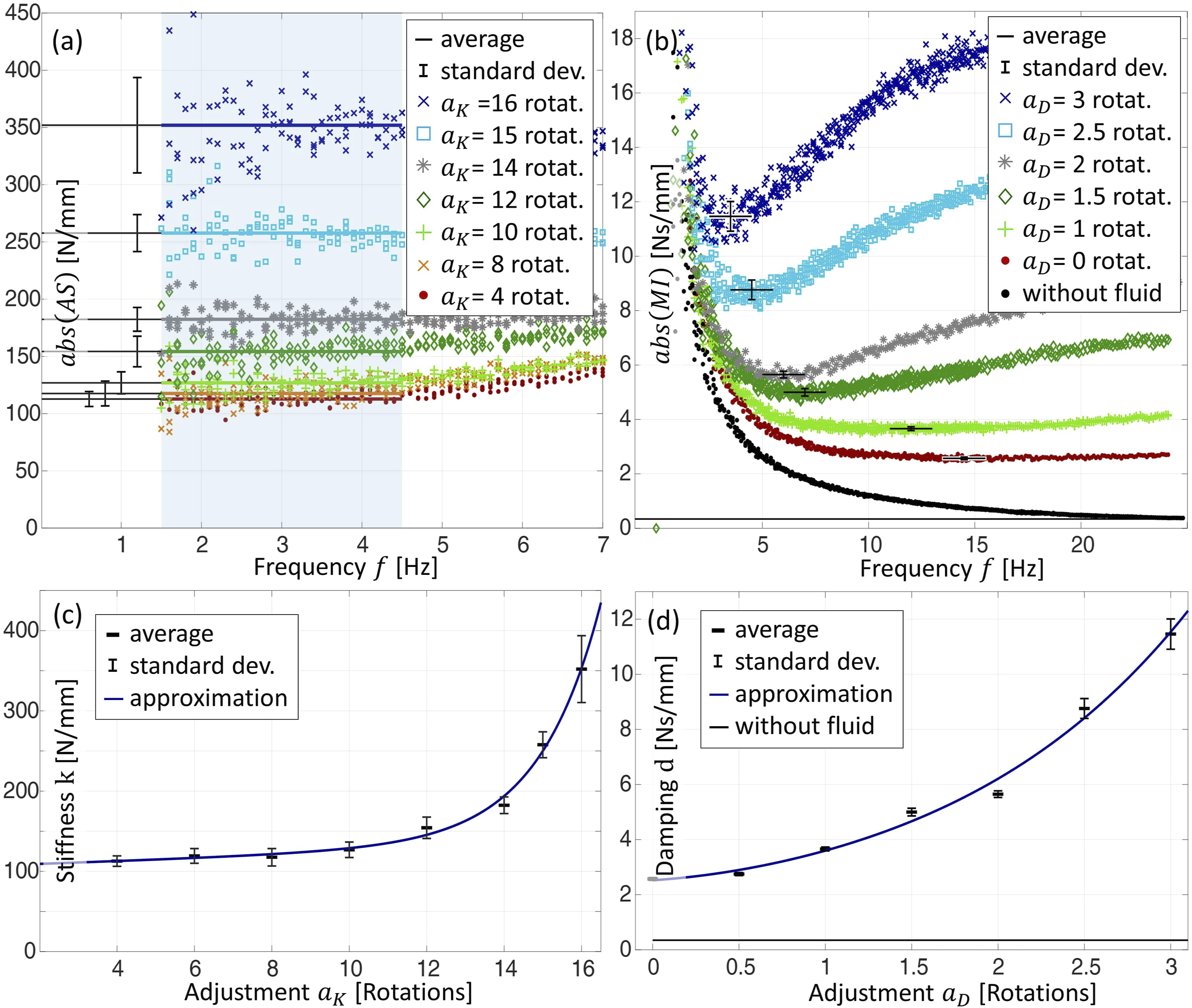
Figure 9(b) shows the mechanical impedance (MI) calculated by the force signal divided by the velocity signal. The resulting asymptote corresponds approximately to the damping value. Figure 9(d) shows the resulting damping behavior from d(a D = 0) = 2.4 Ns/mm to d(a D = 3) = 11.5 Ns/mm. To achieve even lower damping in the later test, an additional test was carried out without hydraulic oil and with open hydraulic chambers. This resulted in damping of d(a D = no fluid)= 0.4 Ns/mm due to friction on guides and seals.
The tests were performed like this for two equal adjustable impedance elements with just slightly different characteristics. The settings were adjusted in the later experiment to give the same properties for both.
Resulting adjustable vibration behavior
This chapter presents the experiment with adjustable impedance elements at the interfaces and shows the vibration reduction that can be achieved. For this purpose, two adjustable impedance elements are used at the two upper connections of the partition to influence its vibration behavior. Figure 10 shows their arrangement. The two lower interfaces remain original. The experimental setup on the partition side continues to be used as in Figure 3. In addition, the pressure and temperature are monitored in the test mode via the sensors attached to the elements. Test setup of the upper attachments of the test setup, showing the two adjustable impedance element (AIE 1 and 2), coupling situation and sensors.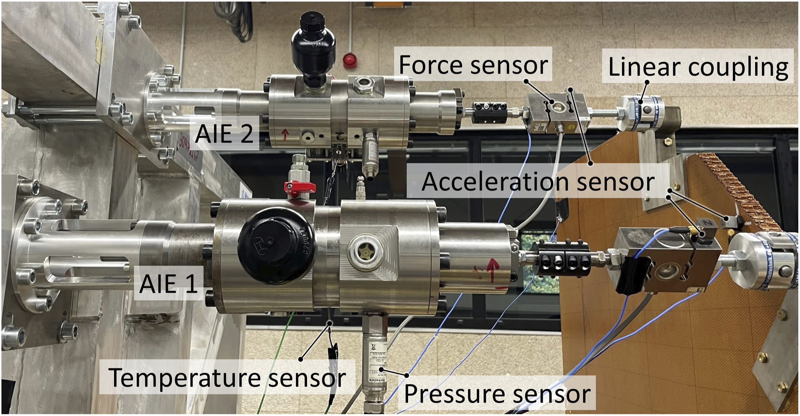
Experimental results
In the experiment, the different stiffness and damping properties of the interface are varied, and the resulting amplifications are determined according to equation (1).
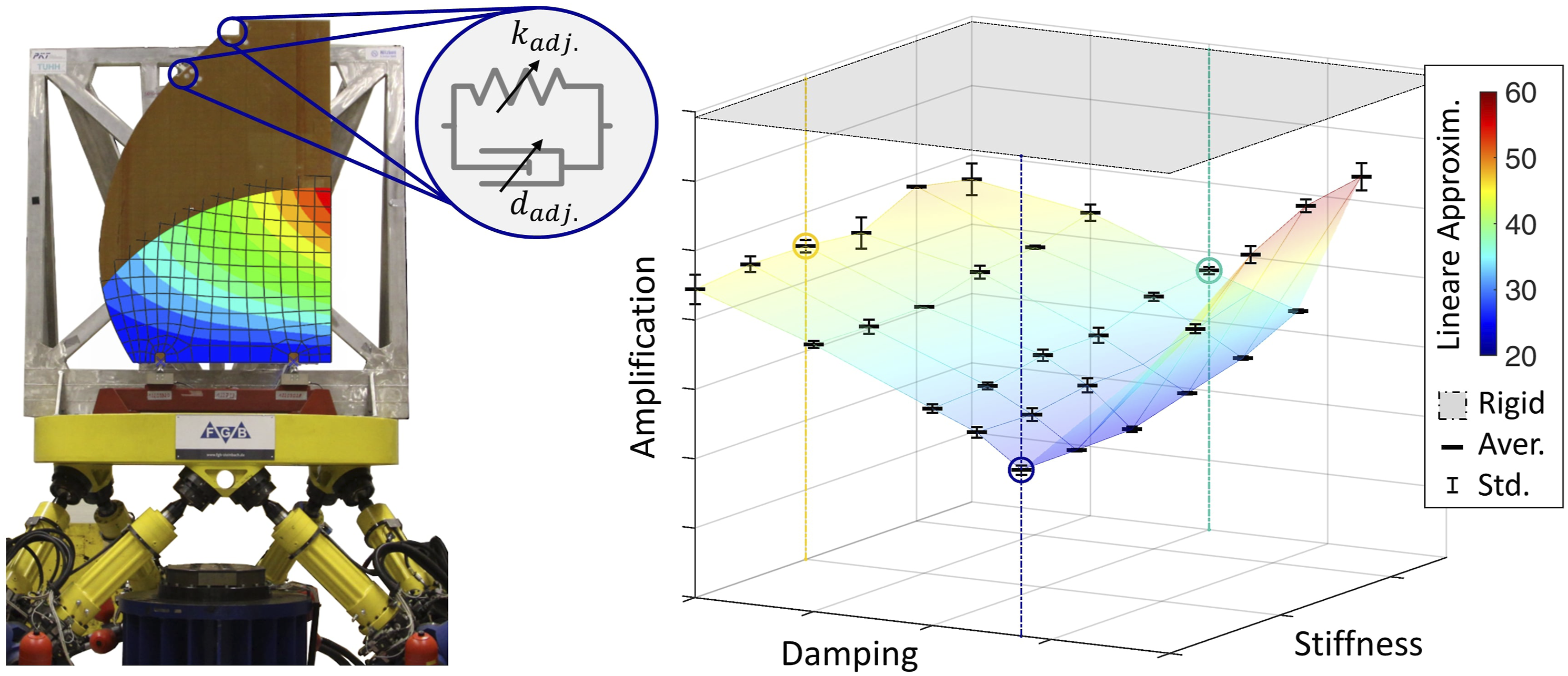
Figure 11(a) shows the resulting amplification HI6,2(f) for three representative stiffness and damping settings. Compared to the experiments with rigid connections, there is a significant reduction in vibration for both resonances. The setting of k = 100 N/mm and d = 2.5 Ns/mm at both adjustable impedance elements results in the maximal reduction. The amplification of the first resonance is reduced by 65% (from 69.3 to 23.9) and for the second resonance by 73% (from 26.0 to 7.2). Experimental amplification of the partition with different interface properties over frequency and the maximum amplification over damping and stiffness values.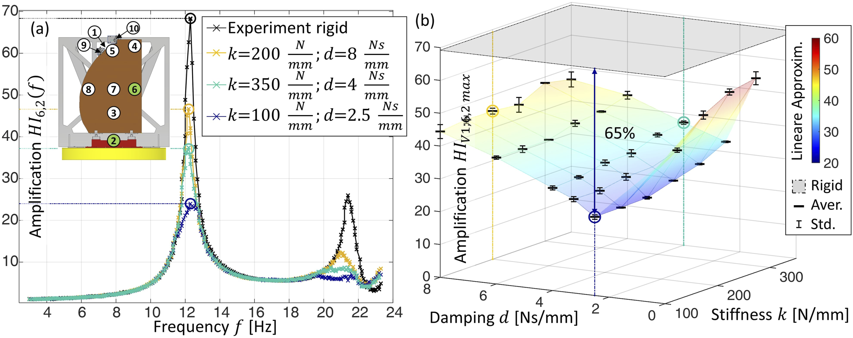
Experiments were performed with triple repetition for all 31 settings studied. The maximum amplification resulted for all cases at the first resonance. Figure 11(b) presents the maximum amplification over the interface properties stiffness and damping. The amplification is shown as average with standard deviation in comparison to the one with rigid connections.
The lowest point is formed at k = 100 N/mm and d = 2.5 Ns/mm. The amplification increases with increasing and decreasing damping. Likewise, it increases with stiffness.
Validation of the results
For validation, the comparison of the simulation model with the physical tests is performed. Figure 12(a) shows the comparison of the amplification over the investigated frequency range with rigid connections at the interfaces and with adjustable impedance elements with optimal interface properties. The experimental data is shown with mean value and standard deviation at the first resonance. The magnitude of the amplification with rigid connections was used to fit the structural damping of the simulation model, and therefore cannot be used to make a comparison. The experimentally determined amplification with the optimal interface properties even leads to slightly higher vibration reduction in the experiment than the simulation predicts. Comparison between experimental and simulated amplification of the partition for rigid and compliant connections over frequency.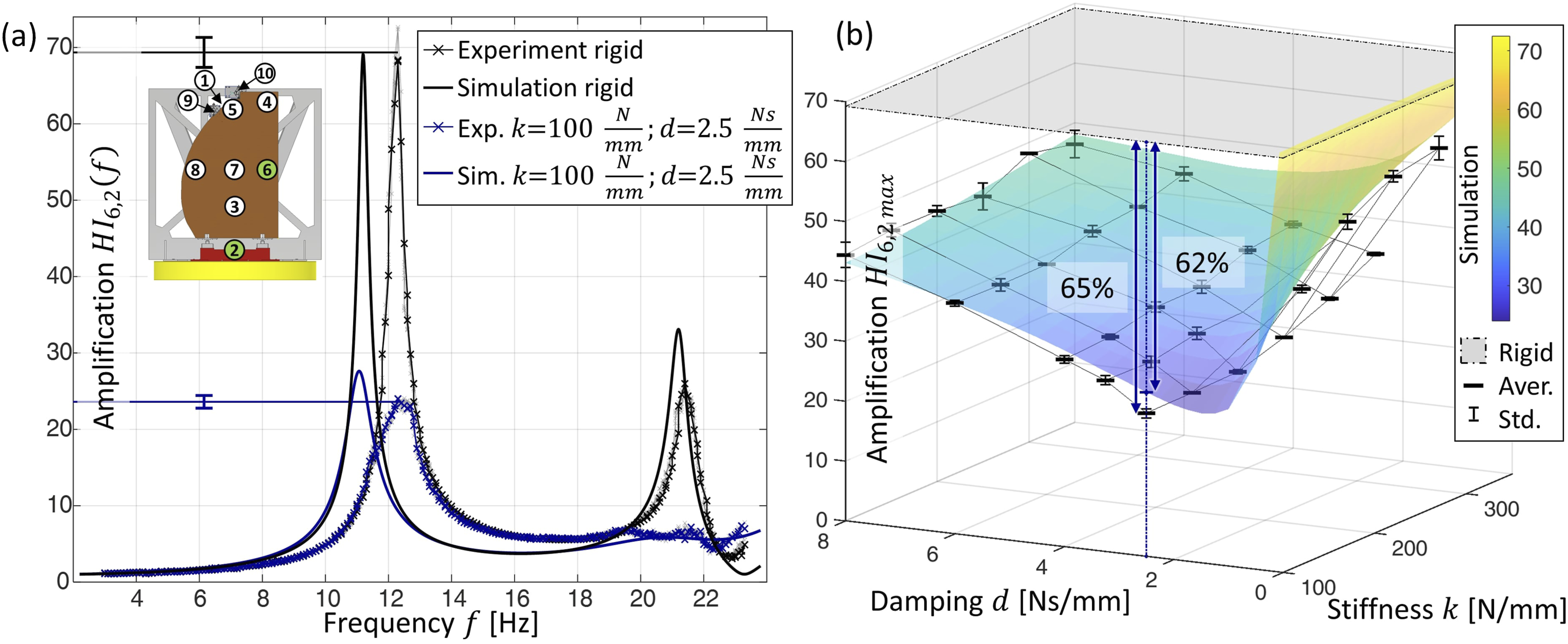
For the first resonant frequency, there is a deviation between the simulated and experimental results. The deviation can result from a discrepancy in the bending stiffness or the inertia of the partition. The simulatively and experimentally determined second resonant frequency agrees relatively well. The stiffnesses are from the manufacturer’s data sheet, and the total mass of the model corresponds to the weighed mass. Different deviations at the first and second resonance frequency show that there appears to be an uneven distribution of stiffness and mass, which affects the first and second mode differently.
In Figure 12(b) the comparison of the gain of the partition from experimental data and simulation results over the interface properties stiffness and damping are shown. Overall, there is good agreement between the simulated and experimental results. The lowest point of the amplification is comparable in simulation and experiment. With increasing and decreasing damping, there is also good agreement between simulation and experiment. The simulated amplifications are close to the mean values with their standard deviation. Only at high stiffnesses, there is a small deviation.
Overall, the results of the experiment and simulation are comparable. The prediction of suitable interface properties is decisive for the applicability of the model. The necessary interface properties for maximum vibration reduction of the partition match.
Student’s t-test can be used to determine the significance of a difference in results from differing values of an input variable. For the distinction between rigid connections at the interfaces to adjustable impedance elements at the interfaces, a clear significance of the results is obtained, with a confidence interval of 99.9%.
Conclusions
The publication shows the potential to achieve significant vibration reduction of lightweight structures by adjusting their interface properties. For this purpose, two topics are addressed. One is the development of an adjustable impedance element to allow settable stiffnesses and damping at the interfaces. On the other hand, the investigation of a partition on a large component test bench to quantify the resulting vibration reduction. The development is accompanied by a simulation model to predict the resulting vibration behavior.
The developed adjustable impedance element shows wide adjustable stiffness and damping ranges, thus demonstrating wide applicability. This extends the existing state of the art of comparable elements, most of them only having either adjustable stiffness or adjustable damping. The development meets the requirements of vibration testing and has proven its usability here.
In the simulation, by adjusting the interface properties, a reduction in vibration of 62 % of the amplification was achieved compared to rigid connections. In the experimental investigation, a vibration reduction of 65% was achieved. The simulated and experimental results over the different interface properties match well.
The resulting vibration reduction makes it possible to significantly reduce critical loads. This results in less stress on the connected structures, making lighter and more efficient designs possible. The adjustable impedance elements used in this work are intended to meet the requirements of vibration resistance, high strength, widely adjustable and dominantly symmetrical mechanical behavior, reliability, and accuracy. In a further step, lightweight interfaces should be developed, which are suitable for the real use in aviation. Here, requirements regarding lightweight construction and durability are gaining in importance.
Adjustable impedance elements make it possible to represent entire ranges of interface conditions in one element. This enables them to map varying interface properties during physical testing, as presented in this work. In addition, they make it possible to react to changing product properties. Partitions in operation can have significantly different dynamic properties due to add-on elements such as screens, baby bassinets and crew seats. The different partition variants require different interface properties for optimal vibration reduction. Adjustable impedance elements can implement these different properties without having to redevelop and replace the interface elements, which enables tests to be carried out efficiently. Investigations into changing product properties will be addressed in future research.
Footnotes
Acknowledgments
Special thanks to Tim Strampe, Nico Sjursen, and Ibrahim Kassem who supported the presented systems through many discussions and their student research.
Declaration of conflicting interests
The author(s) declared no potential conflicts of interest with respect to the research, authorship, and/or publication of this article.
Funding
The research results on which this publication is based are part of the project AIProVE which was funded by Deutsche Forschungsgemeinschaft (399922375, DFG, German Research Foundation) and Schweizerischer Nationalfond (SNF). The statements and information in this contribution do not necessarily represent the opinion of DFG and SNF. Publishing fees supported by Funding Programme Open Access Publishing of Hamburg University of Technology (TUHH).