
Abstract
This publication addresses the development of a compact, adjustable hydraulic damper that meets the requirements for vibration testing. Dampers from the literature do not meet all the requirements, such as compact design, vibration resistance, high strength, broadly adjustable and dominantly symmetrical damping, and modularity. Additive manufacturing (AM) enables the design of integral and compact systems that can compensate for several disadvantages of known damping systems. Three stages of development are presented, from a proof of concept to a prototype manufactured by Stereolithography (SLA) as Vat Photopolymerization (VPP-UVL/P) to a ready-to-use hydraulic damper manufactured by Selective Laser Melting (SLM) as Laser Powder Bed Fusion (PBF-LB/M). The final additively manufactured damper is much more compact due to its geometric freedom in the design phase and requires a much smaller number of components. The damper has been tested over a wide range of operating conditions and has proven its reliable damping performance even under high loads. This performance makes it suitable for many other systems subject to vibration.
Keywords
Introduction
A structure’s dynamic behavior depends on its boundary conditions, which must be taken into account during vibration testing. The boundary conditions are physically defined by connection elements with respective inertia, damping, and stiffness. The connection elements and the structure to be tested interact and must be considered holistically 1 . This interaction must be considered when evaluating the structures in dynamic testing1–3.
Such connection elements with adjustable mechanical properties developed for vibration testing are defined as Adjustable Impedance Elements (AIE) 4 . These elements consist of an Adjustable Stiffness Element (ASE) and an Adjustable Damping Element (ADE), which can be adjusted separately 4 . By systematically varying the properties of the AIE, the vibration behavior of the overall system consisting of the test structure and the interface elements can be affected1,5. This can effect the resonance frequency and optimize the vibration behavior by decoupling and damping at the resonance frequency.
AIEs for use in vibration testing must meet the following requirements: Compactness, vibration resistance, high strength, widely adjustable and dominantly symmetrical mechanical behavior, and applicability (detailed derivation in chapter Requirements).
This publication addresses the development of an ADE, which is one part of an AIE. This ADE is designed to meet the requirements in the field of vibration testing. Since the damping elements from the literature do not meet all requirements for vibration testing, a new damping element is presented in this publication to meet these requirements (detailed information in chapter State of the art).
An integral and compact design can improve three of these requirements, namely, compactness, vibration resistance, and dominant damping behavior. Additive manufacturing (AM) offers the potential to manufacture such integral and compact designs. Some key advantages of AM are design freedom, part consolidation, and functional integration. Through the freedom in design parts with complex geometries and efficiently routed channels can be manufactured. This leads to compact and lightweight parts with a smaller oil volume. Furthermore, by integrating several functions into the part and reducing the part count, the number of interfaces and therefore potential leakage spots can be reduced.
The potential of AM for hydraulic components has been shown in several publications in different fields. Smelov et al. 6 summarized several use-cases in their review paper. More specifically, Barasuol et al. 7 developed a highly-integrated hydraulic smart actuator for robotic applications. Geating et al. 8 integrated the functionality of a hydraulic manifold, a mechanical interface, and the core structure for a quadruped robot into one part. Diegel et al. 9 redesigned a hydraulic manifold for an underground drilling rig, strongly reducing the weight and improving the functionality.
This publication is structured as follows: First, the state of the art of existing ADEs is reviewed and the requirements for ADEs are summarized. Then the development procedures and experimental investigations are defined. Following this, the working principle is derived to establish a symmetrical behavior of hydraulic dampers. First test results of three generations of hydraulic dampers, from a proof of concept over an prototype manufactured by Stereolithography (SLA) defined as Vat Photopolymerization (VPP-UVL/P) by ISO/ASTM 52900 to the final damper manufactured by Selective Laser Melting (SLM) defined as Laser Powder Bed Fusion (PBF-LB/M) by ISO/ASTM 52900, are presented. The frequency response function (FRF) from 3 to 23 Hz of the final SLM damper is presented and discussed. Furthermore, the three damper systems’ advantages and disadvantages are compared, focusing on the comparison between the conventional and additively manufactured systems.
According to the current research status of the authors, this is the first development of an AM hydraulic damper for vibration loads. Lindenmann et al. 10 present a suitable ASE for vibration testing, with which the developed ADE can be used in parallel.
State of the art
AIEs are comparable to adjustable compliant structures, which are more frequently investigated in research 11 . Adjustable compliant structures are commonly known by different terms such as adjustable, controllable or variable - stiffness, damping or compliant - connection, mechanism, actuator, or element 11 . Vanderborght et al. 12 , van Ham et al. 13 , Tagliamonte et al. 14 , and Wolf et al. 15 show with their review papers the wide field of application of these elements. They primarily address the use in robotic applications. In this paper, the literature is limited to adjustable compliant structures that have been studied under vibration loads.
Conventionally manufactured adjustable hydraulic dampers have a wide range of applications in chassis components for bicycles to automobiles. 16 Particularly large ones are used in landing gears of aircrafts. In most applications they are used as shock absorbers that are optimized to absorb an impact coming from below in the compression phase without rebounding. Dixon 16 states that the extension force is three to four times the compression force. These shock absorbers do not meet the requirements of the vibration testing.
A large part of the AIEs listed in the literature are stiffness elements (find more information at Ref. [11]). A smaller part deals with ADEs. Li et al. 17 and Xu et al. 18 developed an adjustable fluid damper by closing a different number of orifices in the piston head of a common fluid damper with shape memory alloy to adjust the damping behavior. Test results are shown in the range from 0.2 Hz to 3 Hz. Catalano et al. 19 present a rotational fluid damper that can be adjusted by varying the gap area and height for a shear flow. In the case of fluid shear friction, a linear flow must first be formed 20 ; this is not necessarily possible in translatory vibration testing and the frequent changes in direction accompanying it. Another possibility is the development of a viscous damper by eddy current. Gosline et al. 21 present an eddy current brake for haptic interfaces and report limitations such as inertia, the power consumption of the electric magnets, and the low damping effect at low speeds.
In addition, some systems vary stiffness and damping independently, providing necessary characteristics for use as an AIE. Xing et al. 22 designed a magnetorheological elastomer and controlled magnetorheological fluid damper for vibration isolation. Sun et al.23,24 and H. Deng et al.25,26 developed shock absorbers with variable damping and stiffness using magnetorheological fluids. Their shock absorbers are designed for vehicle and seat suspensions. They use two magnetorheological dampers, one directly for damping and one to connect two springs in series. The test results of the above designs are shown for up to 4 Hz. Another seat suspension is presented by L. Deng et al. 27 , in which rotating magnetorheological dampers are arranged at the intersection of a scissor-like arrangement. In addition, one of the magnetorheological dampers is directly in the force flow. The other magnetorheological damper is connected in series with a spring, thus changing the stiffness behavior.
In summary, ADEs in the literature that may be suitable for use as interface elements in vibration testing. However, these have not been developed to meet vibration testing requirements and, accordingly, have not been validated over the large test ranges required. For example, the elements presented in the literature have been tested only at low frequencies; as frequencies increase, the influence of inertia and the resonant frequencies to be considered increase as well. The undesirable influence of inertia can be limited by reducing the moving mass, that is, by reducing the mass of the shaft and the volume of fluid moved.
Requirements for adjustable impedance elements
Properties to be achieved
Compactness
Schrade et al. 28 developed a variable stiffness actuator for a lower limb exoskeleton to improve its applicability for walking restoration and the robustness of walking on uneven terrain. Stücheli et al. 29 investigated the compactness of this variable stiffness mechanism to improve the handling of the exoskeleton. Wolf et al. 15 addressed the requirement for compactness to fit in a mobile system as robotic systems. When using AIEs in testing, comparable requirements regarding the system’s compactness have to be considered. The necessity of a compact design in testing is primarily due to the flexibility of using the damper on different test benches with their space requirements.
Vibration-resistance
One criterion for use for dampers in dynamic testing is reliable mechanical behavior over wide frequency ranges10,11. For this purpose, it must be ensured that the elements are vibration-resistant over the frequency range in which they are used. For this purpose, all components must be designed to exhibit as few resonant frequencies as possible in the later operating range. Adjustable compliant elements are often assembled from many components, which is challenging for a controllable behavior, especially at wide frequency ranges 30 . Each component has its natural frequencies and the possibility of fit clearance 31 . Integral design supported by AM can reduce the number of components to a small number of rigid components.
High strength
Especially for testing of heavy components, a criterion is the capability for high loads
30
. Therefore, the system must be designed to withstand the pressure. The hydraulic pressure must always remain above the vapor pressure since otherwise, the oil starts to evaporate and cavitates
20
. Vapor or air in the system can be compressed and would act as stiffness in dynamic testing. Figure 1 shows the pressure over time during a sinusoidal oscillation with amplitude Pressure over time under vibration load of a hydraulic damper.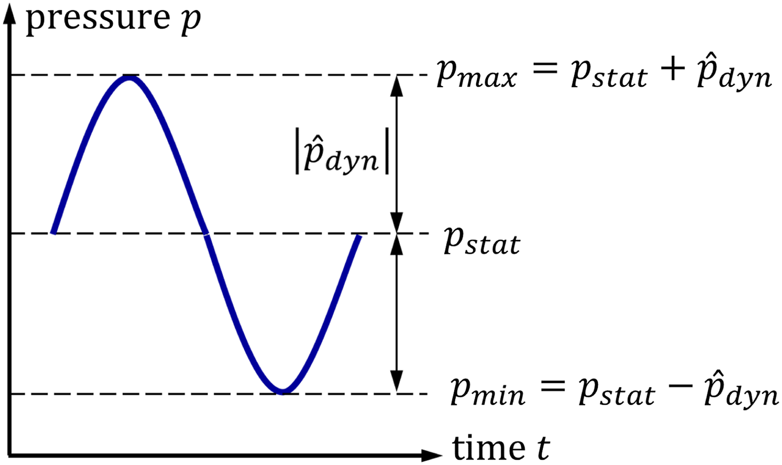


The compressive strength must be selected high enough to withstand the resulting maximum pressure.
Wide range of adjustability
The investigation’s objective is decisive for determining the damping coefficient. This publication does not consider a quantitative determination of the desired damping coefficient since it depends on the test object to be investigated. The test object and interface element must be considered holistically for determination, as they interact with each other 2 . Resonance and anti-resonance phenomena in the connection can lead to under- or overloading and even destruction of the specimen 1 . A wide range of adjustments should be achieved to be applicable for as many test objects and operating conditions as possible.
Damping dominated behavior
The ADE should have as little influence as possible on the stiffness element with which it is connected in parallel order in the AIE. For this, the stiffness of the parts in the flux of force must be set as high as possible 5 . Furthermore, a small mass of the moving parts of the damper should be achieved since additional mass can be added if needed but not further reduced than the designed one. The mass has an increasing influence on the mechanical impedance and thus on the damping behavior, especially at high accelerations associated with high frequencies. The weight of the variable element affects the systems performance by reducing the bandwidth of robotic systems 15 or, in this case, the necessary test range. A minimum mass and a maximum stiffness are constructively contradictory, so a good ratio of these is to be achieved. This is also advantageous for the first natural frequency since this increases with increasing stiffness and decreasing mass 32 .
Symmetric and linear behavior
Typical vibration testing takes place under sinusoidal excitation 2 , so the ADE is also excited with sinusoidal vibrations during testing. The advantage of sinusoidal motions is that acceleration, velocity and displacement are linear with a phase shift to each other. In case of forced vibration, the system under study reaches steady-state behavior and reacts in the same frequency as that of the excitation 33 . In most cases, a transfer value is determined at the respective excitation frequency when investigating the vibration behavior. With an increasing excitation frequency the FRFs apparent mass, mechanical impedance and apparent stiffness can be determined (for more detailed information, see Ref [4]). When the forcing vibration is equal to the system’s natural frequency, the largest magnitude results 33 . When determining the FRFs, the amplitudes of the respective oscillating signals are put into relation. The amplitudes can be determined via the Fourier transform or a best-fit approach. Nonlinear or asymmetrical behavior can lead to deviations. The damper should have an ideally symmetrical and linear damping behavior to avoid this. Furthermore, this makes using the AIE easier when investigating test objects since the modeling of the interface can be implemented linearly and non-linearities are limited to the test object.
Combinability and commonality
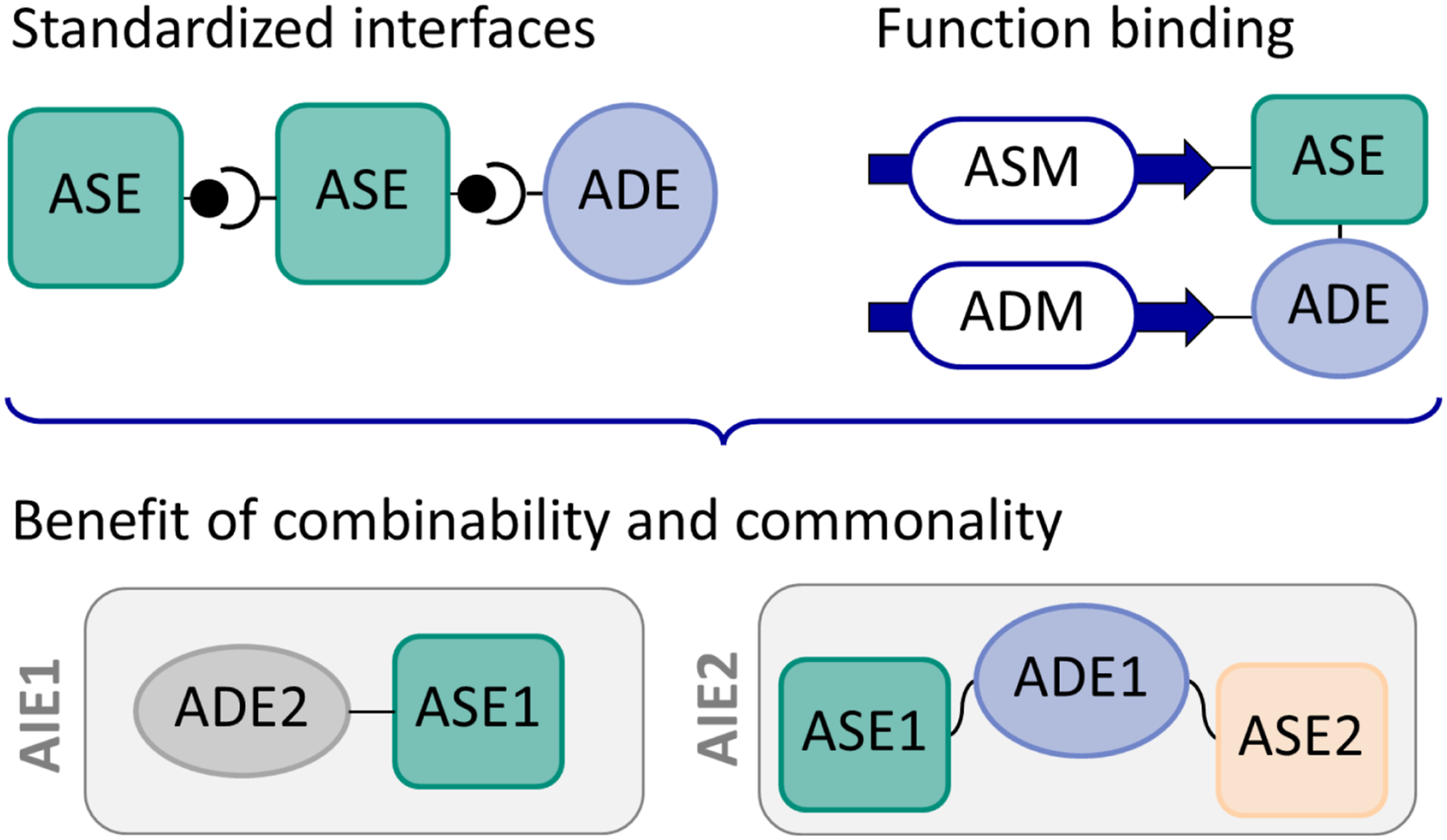
To reduce product complexity, a useful approach is to address product modularity. Modular products are characterized by decoupling, communal use, combinability, standardized interfaces and function binding
34
. The benefit of commonality and combinability of ADEs and ASEs is of interest for use as AIEs. Combining different modules into different product variants makes it possible to offer many products with relatively few elements
35
. The aim is to reproduce a wide range of interface properties by offering a large number of product variants resulting from the combination of different ASEs and ADEs. Communal use makes it possible to reuse developed modules in different product variants. Multiple ASEs and ADEs can also be combined to achieve desired properties. Standardized interfaces and function binding are steps towards the realization of combinability and commonality
35
. Figure 2 presents the standardized interfaces and function binding of the adjustable stiffness mechanism (ASM) and damping mechanism (ADM) to ASE and ADE schematically that allow them to be freely combined and used communally. This will accelerate the development of various new combined elements in the future. Standardized interfaces and function binding leading to combinability and commonality, adapted from Krause et al.
35
.
Resulting requirements for an adjustable damper element
1. A compact design to use the elements on a variety of test benches with their individual space requirements. 2. Small number of components in order to have as few resonances as possible in the operating range. 3. High strength to withstand high forces and provide reliable damping even under high loads. 4. Wide range of achievable damping coefficients to be applicable for different test objects. 5. High stiffness at flux of force while keeping a minimum of moving mass, to reach a damping dominated behavior. 6. Damping behavior as symmetrical and linear as possible. 7. Standardized connections and function binding to reach combinability and commonality.
Materials and methods
Design procedure for AM designs
For both AM prototypes, a function-driven design strategy was followed 36 . A similar design methodology to the one proposed in Leutenecker–Twelsiek et al. was used 37 . After defining the required components, the according interfaces are extracted, corresponding to the function-oriented surfaces. Next, the optimal orientation for each surface is chosen, considering the necessity for support structures, the as-built surface quality, and the potential for the most compact design. Since all components are independent, each component can be oriented independently. After defining the orientation of each function-oriented surface, a compact layout of all surfaces with respect to each other is defined, considering the required channel connections. Finally, the surface model is adapted so that it is compatible with the given manufacturing constraints, for example, adapting the cross-section of horizontal channels to a self-supporting droplet shape. Then a wall thickness is added to the surface model. Additionally, reinforcement bars, post-processing offsets, and clamping surfaces were added where necessary.
Experimental setup and testing procedure
Figure 3(a) shows the test setup at the hydraulic frequency test bench (FGB-630, Fertigungsgerätebau Adolf Steinbach GmbH and Co. KG, Germany) with the load cell (S9M/10 kN, Hottinger Brüel and Kjaer GmbH, Germany). The measurement signals are determined via the force sensor and the twice-integrated signal of the accelerometer (3D 50 g 356A15, PCB Piezotronics Inc, USA). The QuantumX System (MX1601 and MX840B, Hottinger Brüel and Kjaer GmbH, Germany) transduce and record the signals at a sample rate of 600 Hz. The sample rate is more than 25 times the Nyquist frequency and more than twice the recommended sample rate for vibration testing
2
. (a) Physical test setup for validation of the hydraulic damper element; (b) mechanical model of a mass-damper-spring system.
11
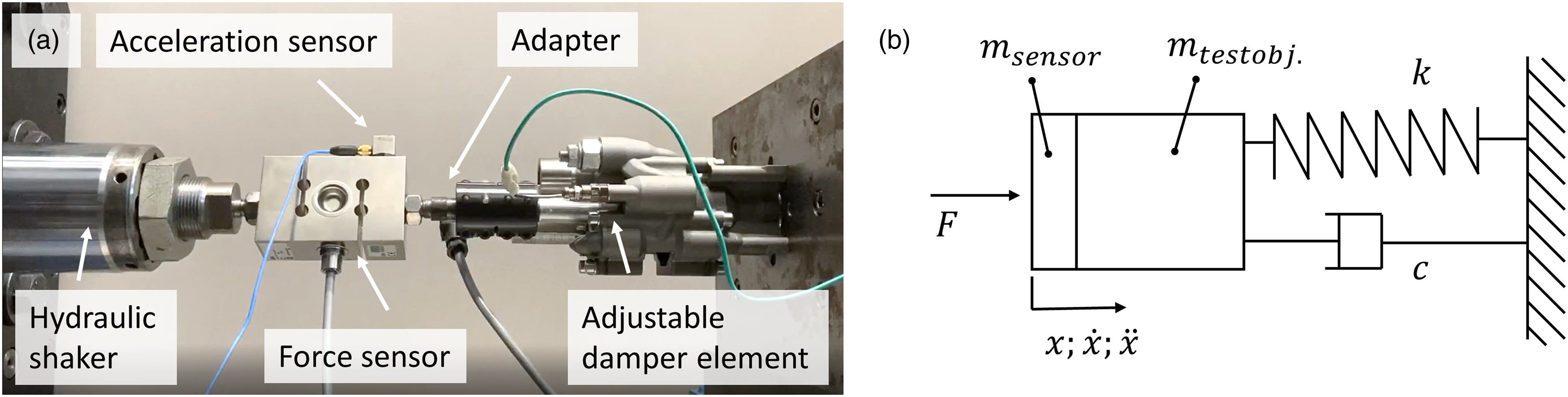
The connections of the test bench are also adapted to the standardized interfaces of the AIEs. The interface on the cylinder side is fixed in rotation and translation and connected to the test stand via four M6 screws. The piston rod is connected to the force sensor of the hydraulic shaker with a clamping coupling.
Excitation and measurement of frequency response functions
For the vibration test a sinusoidal signal is used which is described by x(t),
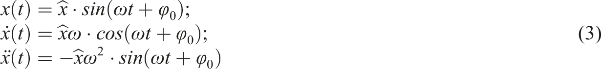
Figure 3(b) shows the mechanical model of the experimental setup. Equation (4) gives the related equation of motion with the resulting spring stiffness k, damping c, and mass m (with m = m
test object
+ m
sensor
).

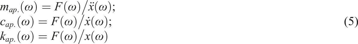
Commonly used in vibration testing are the FRFs apparent mass map., mechanical impedance (MI), and apparent stiffness k
ap
38
. While the mechanical impedance can also be understood as apparent damping cap..
All three dampers are examined per setting in the range from 1 to 25 Hz with different deflection amplitudes from 1 to 5 mm. All dampers are evaluated with stationary frequency excitation with respect to the resulting force over displacement. For the evaluation of the measurement results, the signals are not filtered. The signals are zeroed and the oscillation is settled for 5 s at the time of plotted results.
To determine the FRFs for the SLM-manufactured damper, additional investigations are performed with a sweep excitation in section Results and Discussion. In these test series, the frequency is increased from 3 to 23 Hz with a sweep rate of 0.1 Hz/s at a constant displacement amplitude of 2 mm. The dynamic calibration is performed according to the approach for calibrated measurement of the FRF 11 . The performed calibration is based on the approach of Dong et al. 39 , the mass cancellation of Ewins 38 and the measurement systems FRF of McConnell 40 . The used calibration values are exactly the same as in Ref. [11] with the mass of the adapters and sensors m sensor = 0.863 kg and the measurement systems FRF H I pp .
Development process
Working Principles for adjustable damper mechanism
Viscous dampers with restrictor valves or magnetorheological dampers with an adjustable magnetic field at the orifice are particularly suitable to carry high loads 30 . Magnetorheological dampers and dampers with restrictor valves can decrease their damping coefficient over long-term use by fluid leakage. Furthermore, the viscosity depends on the temperature of the fluid16,20.
Magnetorheological fluids can also reduce their performance due to the precipitation of iron particles 41 . Hard cake (difficulty in re-propagation of residual particle magnetization), clumping, oxidation of particles, separation of fluid particles, and stability are the most common deficiencies in magnetorheological fluids 42 . The use of an ADE for vibration testing requires reliable damping behavior. This is limited due to the large variety of failure modes of magnetorheological fluids, so this principle is not pursued further.
Viscous dampers with restrictor valves are preferred for use as AIEs. Technical solutions can limit or reduce the disadvantages in terms of leakage and temperature-dependent viscosity.
Principle of solution for a symmetrical damper system
In a viscous damper, the restrictor valve and its design are essential for the resulting damping behavior. Typical commercially available restrictor valves have a design as shown in Figure 4. In these valves, the cylindrical needle is moved perpendicular to the orifice, resulting in a geometrically asymmetric design. Very narrow distances between the throttle needle and the orifice plate are necessary to achieve a high damping behavior. Furthermore, the use of the throttle orifice is intended to achieve largely turbulent flow behavior since this reduces the influence of viscosity
16
. Schematic of a commercially available restrictor valve.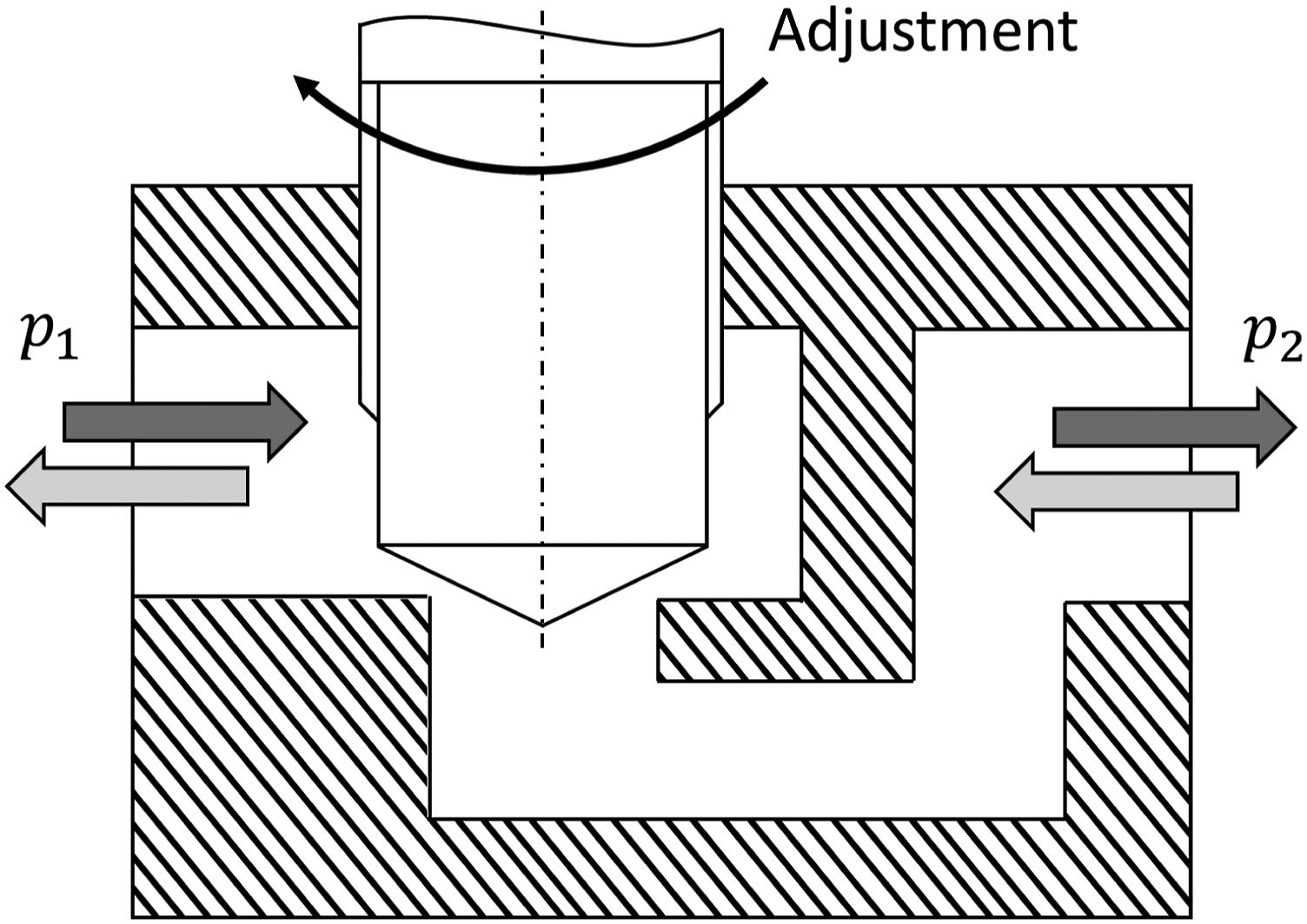
The flow through these restrictor valves is possible from both sides, but the pressure resistance can be different depending on the flow direction (shown in Figure 4). This results in a varying pressure differential between the pressures p1 and p2 and, consequently, different damping behavior depending on the direction of movement of the damper.
Adding a rectifier circuit to a damper allows the direction of flow through the throttle valve to be always from the same direction. Non-return valves can implement the rectification of the flow direction.
Figure 5 shows the resulting schematic design of the hydraulic damper with symmetrical behavior. A piston (Figure 5 pos. 8) in a synchronous cylinder (pos. 3) receives a vibration and transmits it to the hydraulic oil. Depending on the direction of movement of the piston, the oil follows path A or B, depending on the circuit of the non-return valves (pos. 5). This is a type of rectifier circuit with which the oil is always fed to the restrictor valve (pos. 4) from one direction. High pressure must always be maintained in the system to prevent cavitation. By using a hydraulic accumulator (pos. 1), the pressure can be maintained or adjusted if desired. Integrated sensors, such as the pressure sensor (pos. 2) and temperature sensor (pos. 6), are not necessary for the system’s function. However, these help to observe the damping behavior during operation. It is recommended to orient the pressure sensor upstream of the restriction valve as shown in Figure 5, since higher pressures are expected here. At least one temperature sensor should be oriented downstream of the throttle valve to observe the local temperature increase here. Closeable inlets and outlets (pos. 7) are provided on the pipe system for filling under pressure. Schematic of a symmetrical hydraulic damper.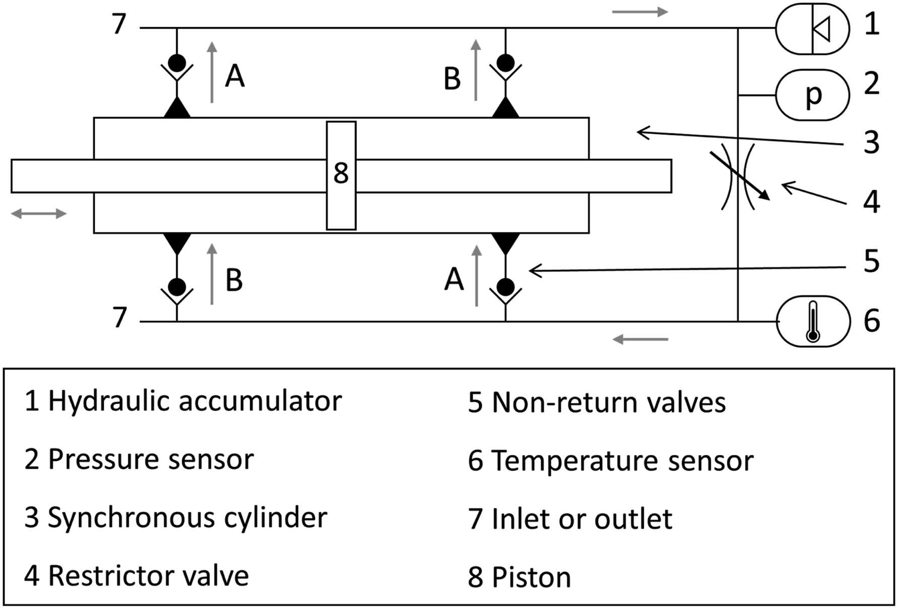
It has two distinct advantages that the oil is always directed to the throttle valve from one direction regardless of the direction of the piston movement: 1. Symmetrical behavior is achieved regardless of the asymmetrical design of commercially available restrictor valves. Asymmetrical behavior in a restrictor valve can result from an asymmetric cross-section-geometry. The throttling of the fluid flow is achieved by a change in cross-section at a throttling orifice. It would lead to an asymmetrical behavior in both flow directions, without the presented schematic design from Figure 5. 2. Due to the rectified circulation of the fluid, the throttle valve is flowed at nearly equal temperature. A design where the throttle valve would be oriented directly between the two piston sides would cause the oil to oscillate locally back and forth in the channel when vibrations are applied. In this case, the local temperature of the oil would rise considerably and thus reduce its viscosity.
Proof of concept with a differential design
The presented schematic design is carried out with commercially available components to obtain a proof of concept in the initial development phases. The first investigations aim to achieve the requirement of a linear and symmetrical damping behavior (see chapter Symmetric and linear behavior) through the design and to determine the achievable damping ranges for the restrictor valve.
Component selection and design
Figure 6 shows the differential design resulting from the scheme of Figure 5. The synchronous cylinder is located at pos. 3, with the four connecting non-return valves on pos. 5. The diaphragm accumulator at position 1 allows it to keep the pressure constant even with low leakage losses. All parts are high-pressure hydraulic components and can withstand pressures up to over 200 bar (equivalent to 20 MPa). Detailed information about the components used for the differential design can be found in the appendix in Table 2. Symmetrical hydraulic damper as a differential system, labels as in Figure 5.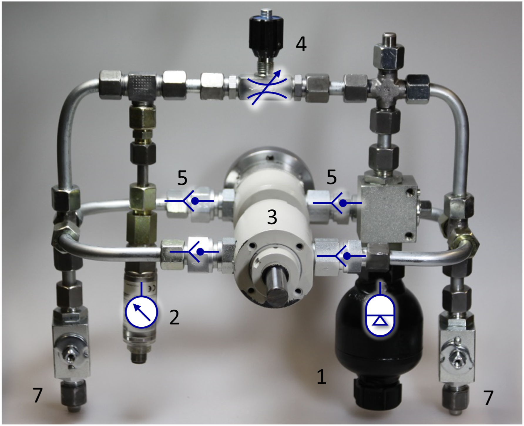
A mineral hydraulic oil (RENOLIN XtremeTemp 46 Plus, Fuchs Schmierstoffe GmbH, Germany) is used, which, due to additives, has a low stick-slip behavior and a relatively low viscosity change over temperature changes. The static pressure in the system is set to 20 bar (equivalent to 2 MPa) to avoid cavitation (see chapter High strength).
Assembly
During assembly, the connecting pipes must be cut to size suitably for the design. When screwing the components together, it is important to ensure that the tightening torques comply with the norms to prevent leakage or failure during operation.
The system is flushed with a hydraulic oil pump to ensure no air bubbles remain in the oil. It must be ensured that no air is left in the system, as this would cause the damper system to have undesirable elastic properties under load. For this purpose, pressure hoses for the inlet and outlet are attached to the connections at pos. 7. After ensuring that the system is filled with oil, the outlet is closed and the system pressure is increased to the required 20 bar.
Testing
The damper was excited at different frequencies with different amplitudes for preliminary tests. Representative test results for the differential design are shown in Figure 7. The resulting force at three adjustments is shown for one sinusoidal oscillation with an amplitude of 3 mm and at a frequency of 10 Hz. The oscillation was already settled for 5 s (equivalent to 50 cycles) at the time of plotted results. The corresponding test procedure and the test setup are explained in section Experimental setup and procedure. Test results for force over displacement from one oscillation at 10 Hz for each adjustment of the differential damper element.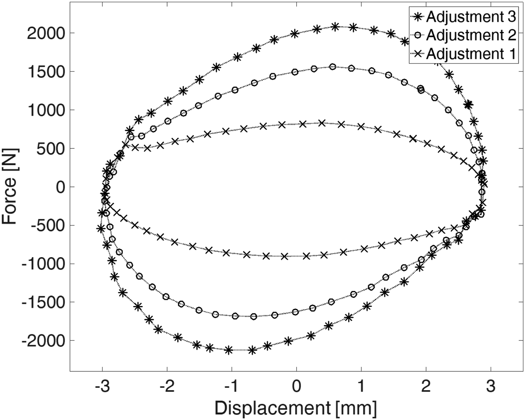
Three different adjustments were examined for the preliminary tests. For adjustment 1, the throttle valve was wide open (open by 5 turns), for adjustment 2, it was at the medium setting (open by 2 turns), and for adjustment 3, it was almost closed (open by 1 turn). Adjusting the restrictor valve results in variability of the resulting force (see Figure 7). A point-symmetrical behavior for the positive and negative range can be seen. The symmetric region is pronounced in the first and third quadrants. This is due to an associated stiffness that overlays the pure viscous damping. This could be due to elastic compression of the fluid or stiffness of the elements in the flux of force.
The resulting damper forces
During the examination, the first resonant frequency was determined at 16 Hz. Heavy components such as the diaphragm accumulator on the long canal pipes began to vibrate. Therefore, testing with high amplitudes is no longer recommended at this point. The installation space of 290 mm × 320 mm × 260 mm is relatively large.
Conclusion on fulfillment of requirements
Summary of the fulfillment of the requirements from section Requirements. - A non-compact design - Components reach resonance already at low frequencies + Withstands high forces and provide reliable damping under high loads + Good range of damping coefficient - Moderately high stiffness at flux of force but relatively large moving mass + A nearly symmetrical and linear damping behavior + Standardized connections and function binding
The challenges of a compact design, fewer components that resonate, and reduced moving mass can be met by an integral design. AM is a sensible solution for producing compact and geometrically complex structures as required.
SLA-manufactured prototype
After the evaluation of the differential design, the goal of the next iteration is to achieve a more compact design that, at the same time, is more vibration-resistant. Therefore, Stereolithography (SLA known as VPP-UVL/P) is chosen due to its freedom in design, allowing the manufacturability of complex and compact channel geometries. During the SLA process, an object is created by selectively curing a polymer resin, layer-by-layer using an ultra violet laser beam (UVL). Parts manufactured with SLA have a smooth surface and good quality fine details. However, the material is quite brittle.
Component selection and housing design
The required components are identified based on the functional requirements from the hydraulic scheme (see Figure 5) and the differential design. These, combined with the connections between the components, form the basis for the SLA design when following the approach of a design based on function-oriented surfaces. Two types of components are required for the given design: screw-in and insert components. Screw-in components can be attached to the damper housing by a thread (such as the sensors (2, 6), the restrictor valve (4), and the inlet and outlet of the system (7)). Insert components must be assembled between different parts of the damper housing (such as the non-return valves and the piston). Both types of components are exemplarily shown in Figure 8(a). Detailed information about the components used for this AM design can be found in the appendix in Table 2. (a) Two types of required components (exemplarily shown on a selection); (b) General design concept based on functional and assembly requirements, with optional aluminum plates due to strength limitations of SLA components for threads.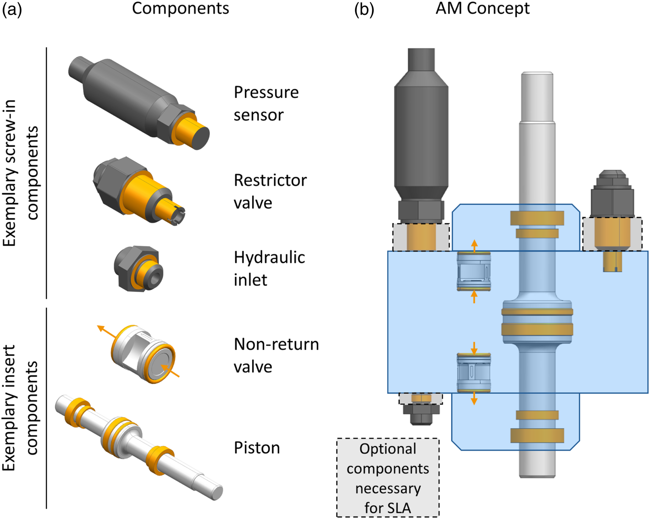
Next, the components are placed in a compact layout considering the required channel connections. Under consideration of the number of housing parts and a compact design, a design concept with one main housing part and two lids to enclose the insert components (piston and non-return valves) is chosen. This concept is displayed in Figure 8(b). Furthermore, three aluminum plates are integrated into the design due to the necessity for stable threads which accommodate all screw-in components. Based on these design and assembly considerations, the component layout is adapted by adding the optional components necessary for SLA.
After finalizing the layout, the interfaces of the given components are extracted and connected with the required channels. Figure 9(a) shows the extracted function-oriented surfaces in the final layout. Finally, the voids between the component interfaces are filled to achieve a stable design. Figure 9(b) and (c) show the resulting final design. The two SLA housing lids and the aluminum plates are connected to the main housing part with screws and threaded inserts. For a better visibility, the threaded inserts, as well as seals and screws, are not displayed. (a) Final function-oriented surface layout of the SLA design; (b) SLA design with components; (c) Exploded view of the SLA design.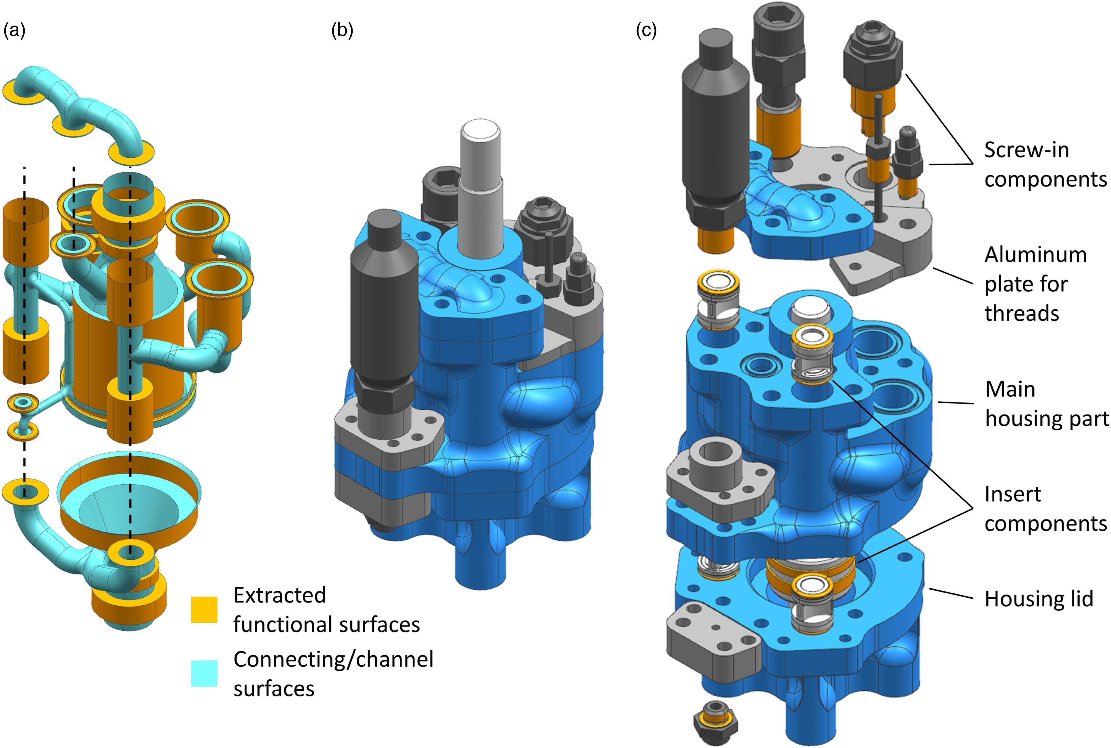
Manufacturing, post-processing, and assembly
The housing components are manufactured out of the material Tough V4 on a Form 2 printer using SLA. Next, they are post-processed by the Form Wash and Form Cure (all devices from Formlabs Inc., Somerville, USA), and the fitting and sealing surfaces are then machined. Figure 9(b) and (c) show all components. The necessary screw-on parts are attached with threaded inserts or metal attachments since threads in resin parts cannot withstand the loads due to the pressure and the exciting force. Figure 10 shows the assembled damper system. At 181 mm × 96 mm x 107 mm, the installation space is significantly smaller and requires less space than the differential system. Prototype of an AM symmetrical hydraulic damper (labels as in Figure 5).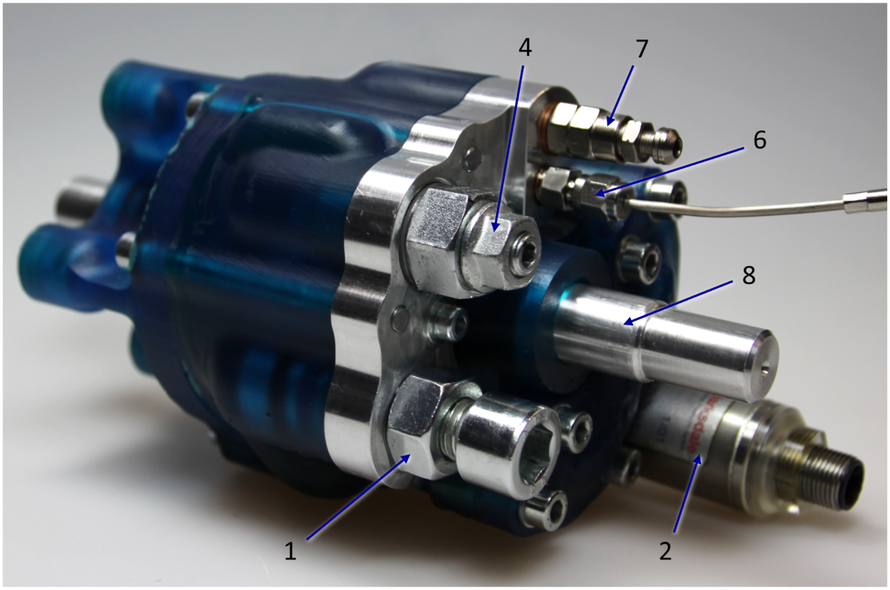
Testing
The SLA-manufactured prototype was excited for preliminary tests at different frequencies with different amplitudes. Representative test results are shown in Figure 11 for an exciting frequency of 5 Hz and a displacement of 5 mm. Three different settings were examined for the preliminary tests. In the first state, the valve was wide open (adjustment 1 - open by 4 turns). In the second state, the valve was closed slightly (adjustment 2 - open by 3 turns), whereas it was further closed in the third state (adjustment 3 - open by 2.5 turns). The almost closed setting was not tested since the material could not withstand these resulting pressures. Note that the throttle valve is different from the previous one, and so are their settings. Test results for force over displacement from one oscillation at 5 Hz for each adjustment of the SLA damper element.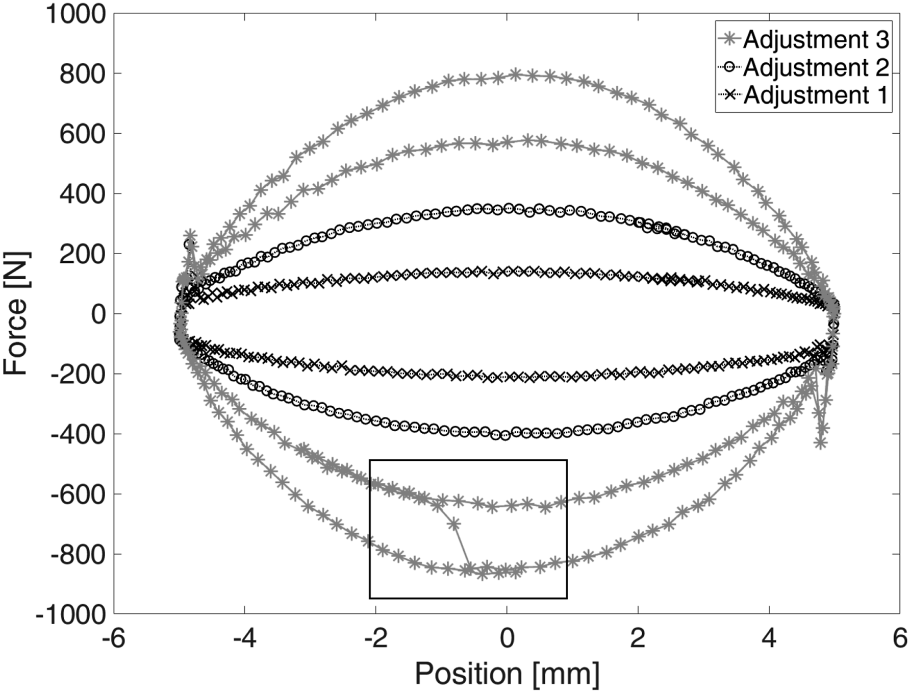
The experiment results show a symmetrical uniform behavior. The damping of the SLA design is lower compared to the differential design, so the static friction is clearly visible with up to 400 N at maximum deflection. The damper can be adjusted by varying the restrictor valve, which leads to resulting forces between 150 and 820 N for the presented results. These are related to a damping constant of 0.96–5.22 Ns/mm.
During the prototype testing, there was an abrupt reduction in the resulting force from 820 N to 620 N. The moment this happened is shown in the highlighted rectangle in Figure 11. From this moment on, the flow resistance in the system was lower. Subsequent examination of the prototype revealed small plastic parts of the housing in the hydraulic oil and abrasion in the area of the restrictor valve. This observation indicates that the thermoset’s strength is insufficient for this hydraulic application in the long term.
Conclusion on fulfillment of requirements
+ A compact design + Components do not reach resonance in the tested frequency range - Does not withstand high pressures, resulting in an unreliable damping + Good range of damping coefficient - Moderately low moving mass but low stiffness at flux, as the housing slightly deforms elastically under load + A symmetrical and linear damping behavior + Standardized connections and function binding
SLM design
The SLA design showed satisfactory results and fulfilled the aspired goals regarding a compact design. However, the mechanical properties of the SLA design do not fulfill the requirements for the damper under high pressures and loads. Therefore, in a further iteration, an Selective Laser Melting (SLM known as PBF-LB/M) design was developed.
Component selection and housing design
Due to the satisfactory results regarding compactness, the selected components from the prior iteration were adopted.
Therefore, the required interfaces for connecting the components to the housing stayed the same. Furthermore, the overall layout of the components could be adopted. The main changes in the design are related to the material properties of the stainless steel, SLM process restrictions, and post-processing considerations. Due to the use of metal, the necessity for separate aluminum plates to connect the threaded components was omitted. This reduces the number of housing parts to three, with one central housing part with two lids to enclose the piston and the non-return valves. Most components were placed flush on two planes to reduce the post-processing effort if not required otherwise. Next, the function-oriented surfaces were moved as close together as possible to achieve a lightweight design while still leaving enough wall thickness and allowing the assembly of the components. Furthermore, the horizontal channels with a larger diameter were adapted to a droplet shape to ensure manufacturability in the SLM process without requiring internal support structures. The function-oriented surface model is shown in Figure 12(a). Finally, a wall thickness was added to all surfaces and parallel clamping surfaces were added to enable post-processing. The final damper design is depicted in Figure 12(b) and (c). (a) Final function-oriented surface layout of the SLM design; (b) SLM design with components; (c) Exploded view of the SLM design.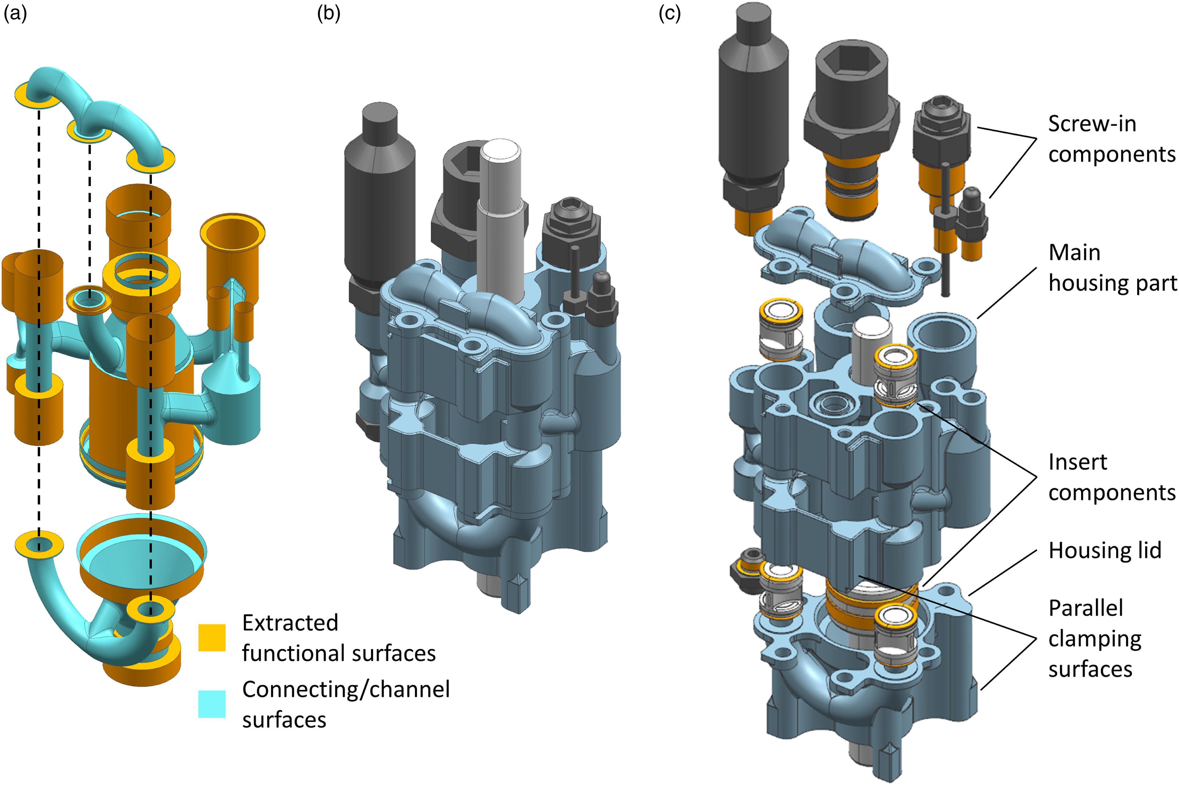
Manufacturing, post-processing and assembly
The three housing components were manufactured on a Concept Laser Mlab cusing R L-PBF machine out of stainless steel 1.4404. All functional sealing and gliding surfaces were post-processed on a CNC machine and the threads were added. Figure 13 shows the final assembled SLM design. The symmetrical hydraulic damper manufactured using the SLM process (labels as in Figure 5).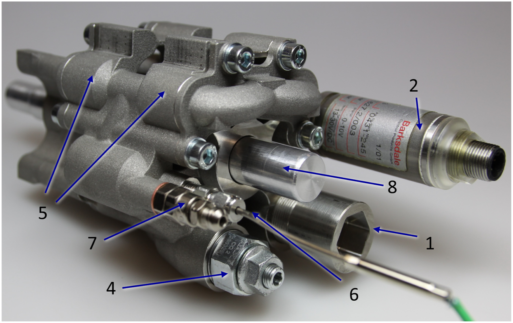
Testing
Like the previously presented damper systems, the system manufactured by SLM is also examined under various test conditions. Further investigations of this system over the entire frequency range follow in the results in chapter Results and Discussion. Considerably higher loads can be achieved than with the SLA-manufactured damper. Figure 14 shows the force at an exciting frequency of 10 Hz and a displacement of 3 mm. The damper can be adjusted by varying the restrictor valve, which leads to resulting forces between 300 and 1300 N for the presented results. These are related to a damping constant of 1.6–6.9 Ns/mm. At the first adjustment, the valve is wide open (open by 4 turns). For adjustment 2, it is closed a bit (open by 3 turns), followed by adjustments 3 and 4 (open by 2.5 and 2 turns), respectively. Test results for force over displacement from one oscillation at 10 Hz for each adjustment of the SLM damper element.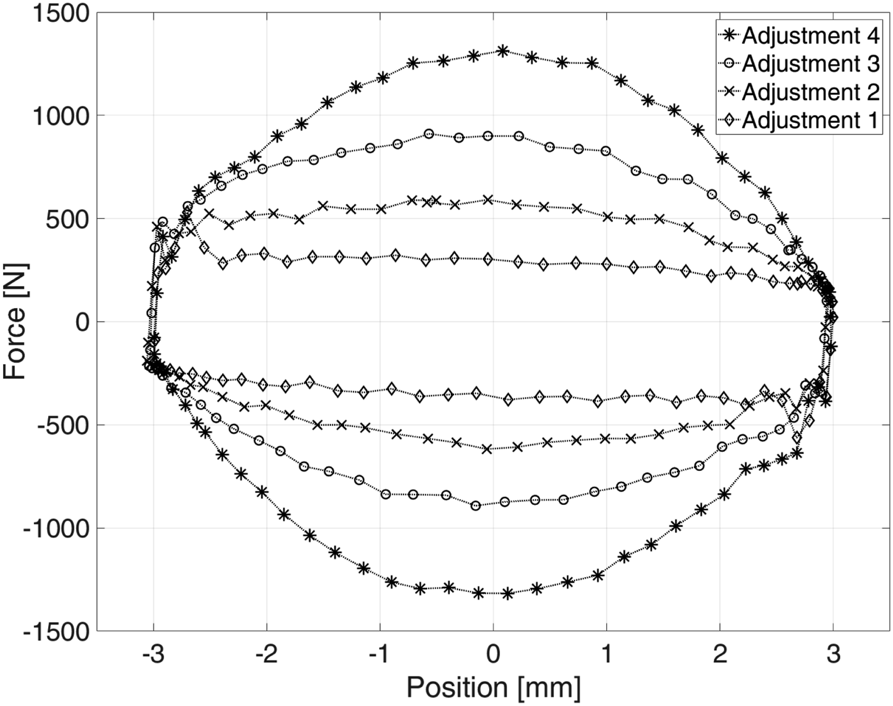
Conclusion on fulfillment and requirements
+ A compact design + Components do not reach resonance in the tested frequency range, the first resonance was reached at 40 Hz + Withstands high pressures and resulting in a reliable damping + Good range of damping coefficient + Small moving mass with high stiffness at flux are reached + A symmetrical and linear damping behavior + Standardized connections and function binding
Results and discussion
Response behavior and mechanical characterization
For the SLM design, Figure 15 shows the resulting FRF for the apparent mass map., mechanical impedance cap., and apparent stiffness kap.. Each data point represents the behavior of the belonging oscillations at the given frequency. The FRFs are derivatives of each other and their representations each have advantages in evaluating different properties of the elements under investigation
11
. Calibrated FRFs kap., cap., map. and its phase for each adjustment of the SLM damper element over frequency.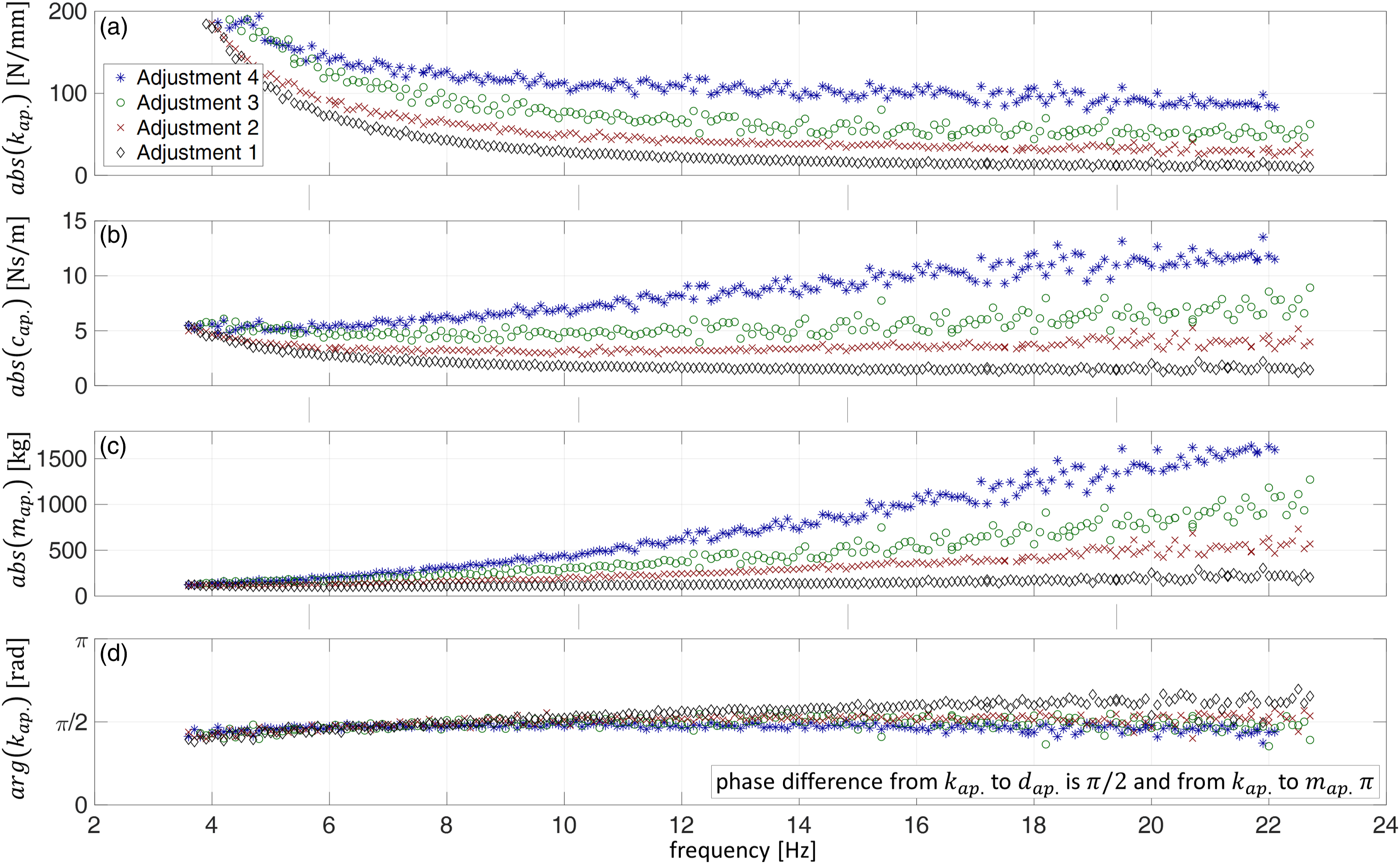
The plot in Figure 15(a) of the apparent mass shows parabolic curves as they are typical for mechanical damping 43 . The resulting damping behavior can best be interpreted in the plot of the mechanical impedance, which in rough approximation forms constant values in Figure 15(b). The test results in Figure 15(c) of the apparent stiffness show a linearly increasing behavior as it is expected for a damping behavior in this representation 43 . An ideal damper’s phase difference between force and displacement is π/2. The phase difference between force and displacement corresponds to the angle of kap., which ranges from 1.2 to 2. Overall, the test results show a reliable damping response over the investigated frequency range from 3 to 23 Hz.
Depending on the adjustment, clearly separated behavior can be seen in all three plots of the FRFs in Figure 15(a)–(c). The damping characteristics depending on the adjustment can be compared in the mechanical impedance plot, shown in Figure 15(b)). It is noticeable that in the range around 3 Hz, the mechanical impedance is the same for all four adjustments. In this range, the velocity is still very low, so the behavior is dominated by Coulomb friction. Also, in tests with velocities close to 0 m/s, a friction force of about 300 N is formed (similar to Figure 14 for Adjustment 1). The viscous damping behavior dominates only with increasing frequency and the accompanying increasing velocity so that the different responses can be separated clearly.
For adjustments 1, 2, and 3, the mechanical impedance cap. is approximately constant for frequencies above 6 Hz. However, it is noticeable that the mechanical impedance for adjustment 4 shows a considerable positive gradient. According to the authors, this is not a force resulting from the moving mass of the oil and the piston rod, as this behavior should also be seen at the lower adjustments. It is much more likely that this behavior is due to the increase of turbulent flows at the restrictor and in the belonging channels. The fluid damping resulting from the energy dissipation of a turbulent flow is proportional to the square of the flow rate 16 , and thus a linear curve in the mechanical impedance. At the same time, achieving a turbulent flow also has the advantage of being independent of a change in temperature 16 . In the damping system, there is a combination of laminar and turbulent flow. With a smaller orifice opening, the velocity increases locally and so does the influence of the turbulent flow.
The phase difference between force and displacement in Figure 14(d) shows approximately constant values around π/2. At the lowest adjustment (adjustment 1), the resulting inertia force can be seen since the total force is small. The related phase difference here is greater than π/2, since the inertial forces with a value of π are involved. With increasing total forces, the compressibility of the fluid and the damper components increases so that the resulting stiffness at a value of 0 has a greater influence on the test results. Therefore, the phase difference value tends to be smaller at higher adjustments.
Further investigations not included in this publication show an unsteady behavior at higher frequencies. These investigations have been carried out on an electrodynamic shaker (presented in Ref [30]) and follow the experimental setup and the associated presented multisine excitation of Lindenmann et al. 10 It is suspected that the unsteady behavior is due to a resonance in the non-return valves of the damper system. The test results show this unsteady behavior for frequencies higher than 40 Hz. However, it cannot be assumed that this resonance already occurs at 40 Hz, since higher frequencies are also excited simultaneously by the multi-sine excitation.
Comparison of the different designs
Overview on fulfillment of requirements (see section Requirements) and related properties.
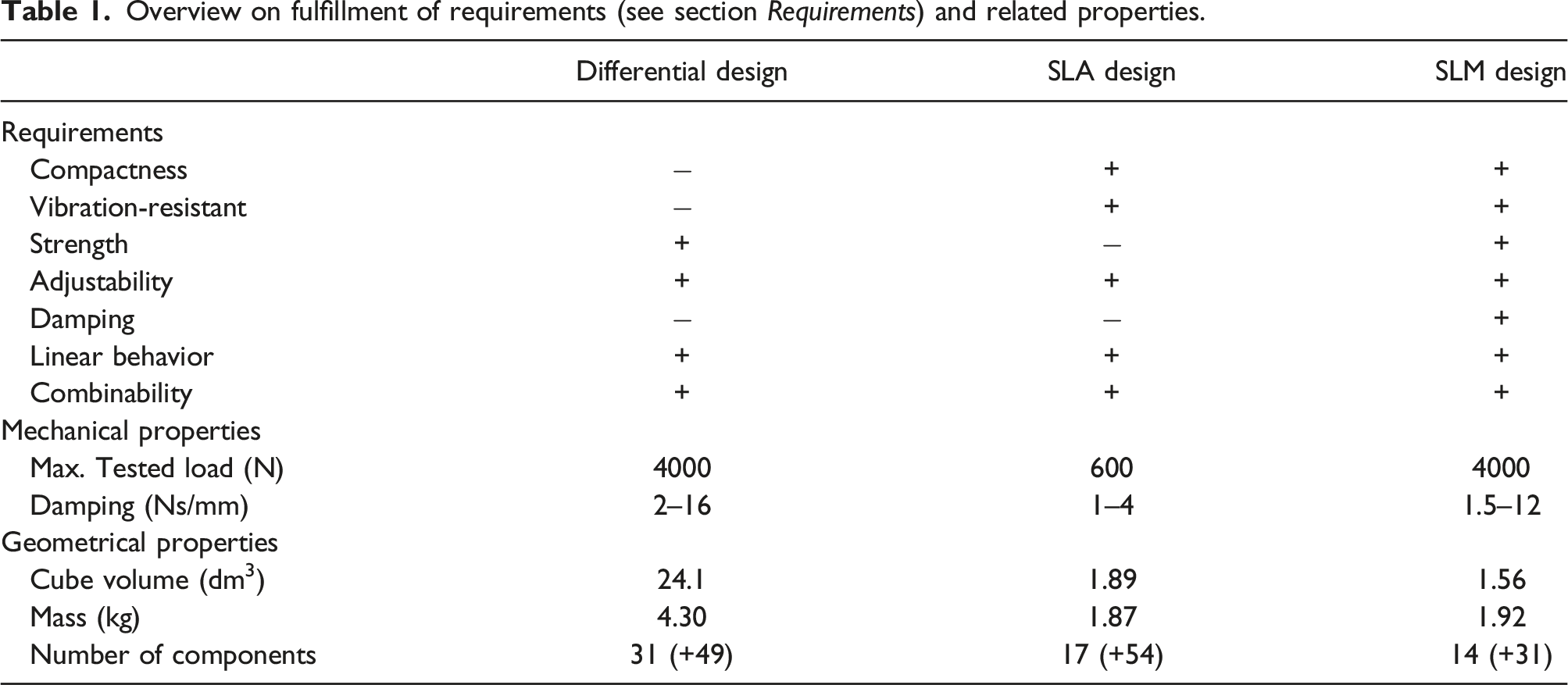
The mechanical properties of the differential and the SLM design are higher than those of the SLA design. This results primarily from the higher strength of the used materials. Consequently, a wider damping range can be achieved since the system can withstand the high pressures generated when the restrictor valve is closed.
Regarding geometrical properties, the two AM dampers are significantly more compact due to their geometrical freedom in the design phase. Table 1 shows the resulting cube volumes of the required installation space, which is the product of the length, width and depth. The mass is more than halved from the differential system to the AM dampers. The mass of both AM dampers differs only slightly. The SLA damper has the lowest weight, but the lowest strength accompanies this. The number of components in Table 1 corresponds to the number of required housing parts and components. Shown in brackets are small standard parts like bolts, nuts, guides and seals. This shows a significant reduction in the part count for the two AM designs. The number can be reduced even further from the SLA to the SLM design.
In summary, the hydraulic damper made with SLM combines the advantages of the differential and SLA design while not exhibiting their limitations. The SLM design provides a good damping performance over a wide range of operating conditions while maintaining a compact design. This makes it suitable for use as a damper in vibration tests and many other systems subject to vibration.
Outlook and conclusion
Only some of the adjustable compliant elements presented in the literature have been investigated under vibration loading, and if so, then only in narrow frequency ranges. For this reason, it was impossible to answer whether these systems could be considered as interface elements in vibration test rigs. The iterative development process from a differential design to a proof of concept through an SLA-manufactured prototype resulted in a ready-to-use SLM–manufactured system. This system was tested in a frequency range of 3–23 Hz and showed reliable, symmetrical damping behavior.
A better understanding of the damper’s behavior requires further work in terms of modeling and simulation based on fluid mechanics. The model has to take into account the equations regarding the fluid continuity, the force equilibrium, and flow-pressure. Especially the modeling at the restrictor valve with the high-pressure gradients and high flow velocity has to be considered in detail. Upcoming work will address this topic.
By using SLM, its possible to develop a damper system that met the requirements for the use as a interface element in vibration test stands. According to current knowledge, this is the first published hydraulic damper in which a large proportion of the functions is realized using AM components. This development supports that the development of hydraulic systems using AM is possible, as it has already been successfully demonstrated for other hydraulic components (reviewed among others in Ref [6]).
Conventional hydraulic dampers have been optimized over many product generations and are specialized for their field of application. This publication focuses on the design process and demonstration of the manufacturing of complex hydraulic systems by AM. Based on the findings of the presented work, systems can be adapted and optimized for more specific applications with their respective requirements. Further research and development in AM will show how well these hydraulic systems can compete with conventional systems regarding size, properties, reliability, and costs. The size of the damper corresponds to that of automotive dampers and can also compete with most of their mechanical properties. According to Dixon 16 , typical load ranges of automotive dampers are below 1000 N and frequencies from 1.5 to 6 Hz must be damped. In addition, the typical damping values range from 0.2 to 0.8 Ns/mm 16 . The SLM damper meets the load range and frequency requirements. Only the requirement for the damping value of automotive dampers is not met, as this range is lower than the damping values of the dampers presented. However, it should be possible to achieve these lower damping values by using low-friction seals.
The adjustable hydraulic dampers presented are to be combined with an ASE for use as interface elements. For developing these spring elements, the requirements for using a stiffness element must be modified slightly. In cooperation with the Institute of Product Engineering (IPEK), at Karlsruhe Institute of Technology (KIT), ASEs have already been developed that have the same standardized interfaces and can thus be combined with the dampers presented. For example, the variable stiffness mechanism of Lindemann et al. 10 should be mentioned. As the number of ASEs and ADEs increases, it is reasonable to create a selection catalog to guide engineers and researchers in selecting such elements.
Footnotes
Acknowledgments
Special thanks to Rafael Neves, Karl-Phillip von Berg, and Amir Nazari, who supported the presented systems through many discussions and their student research. Furthermore, our thanks go to Dario Fenner for the manufacturing and post-processing of the components.
Declaration of conflicting interests
The author(s) declared no potential conflicts of interest with respect to the research, authorship, and/or publication of this article.
Funding
The research results on which this publication is based are part of the project AIProVE which was funded by Deutsche Forschungsgemeinschaft (DFG, German Research Foundation) and Schweizerischer Nationalfond (SNF) - project number 399922375. The statements and information in this contribution do not necessarily represent the opinion of DFG and SNF. Publishing fees funded by the Deutsche Forschungsgemeinschaft (DFG, German Research Foundation) – project number 491268466 and the Hamburg University of Technology (TUHH) in the funding program *Open Access Publishing*.
Appendix
Overview of used components.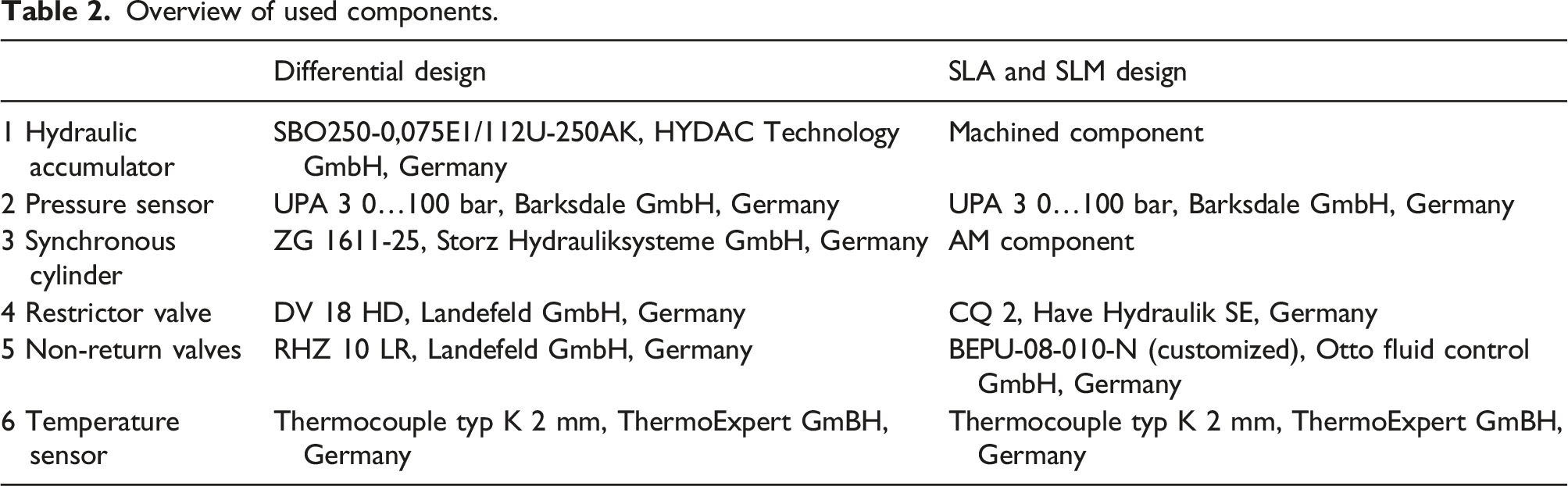
Differential design
SLA and SLM design
1 Hydraulic accumulator
SBO250-0,075E1/112U-250AK, HYDAC Technology GmbH, Germany
Machined component
2 Pressure sensor
UPA 3 0…100 bar, Barksdale GmbH, Germany
UPA 3 0…100 bar, Barksdale GmbH, Germany
3 Synchronous cylinder
ZG 1611-25, Storz Hydrauliksysteme GmbH, Germany
AM component
4 Restrictor valve
DV 18 HD, Landefeld GmbH, Germany
CQ 2, Have Hydraulik SE, Germany
5 Non-return valves
RHZ 10 LR, Landefeld GmbH, Germany
BEPU-08-010-N (customized), Otto fluid control GmbH, Germany
6 Temperature sensor
Thermocouple typ K 2 mm, ThermoExpert GmBH, Germany
Thermocouple typ K 2 mm, ThermoExpert GmBH, Germany