
Abstract
Underwater sound absorption materials with a stable performance at various hydrostatic pressures are important for marine applications. However, most studies about underwater sound absorption materials only focused on the performance at atmospheric hydrostatic pressure, while ignoring the influence of various hydrostatic pressures. Aiming to improve the underwater sound absorption stability of a metamaterial at various hydrostatic pressures, different structures and a Nelder–Mead algorithm with an acoustic-structure fully coupled finite element method (FEM) model are developed to optimize the structure of the metamaterial at various hydrostatic pressures. In this numerical modeling, the metamaterial is a PDMS matrix embedded with periodic cylinders. Firstly, the effect of hydrostatic pressure on the metamaterial is evaluated in the frequency range [0, 8 kHz]. Secondly, different cases are designed to improve the underwater sound absorption stability at various hydrostatic pressures, including different cylinder radii, different distances between the air cylinder and the steel backing, and different void shapes. Then two layers of air and/or steel cylinders are introduced to further improve sound absorption performance under various hydrostatic pressures. The results indicate that PDMS with two layers of air cylinders have the optimal sound absorption stability performance under various hydrostatic pressures, which can be attributed to the top layer of air cylinders absorbing the main deformation. Lastly, the optimization algorithm significantly improves the sound absorption performance of the metamaterials at various hydrostatic pressures. This combination of an optimistic algorithm and FEM can guide the design of underwater sound absorption metamaterials at various hydrostatic pressures.
Introduction
Manipulation and control of underwater noise not only are important for protecting marine animals, 1 but also play a critical role in improving the stealth technology of submarines. 2 Hence, underwater sound absorption materials are developed and widely employed for underwater noise control. Rubbery materials with inclusions are a typical candidate as underwater sound absorption materials for maritime applications. For the inclusions, the air cavity inclusion is a particularly simple and effective inclusion.3–6 Sound waves can be attenuated by thermal, viscous dissipation and resonance of the air cavity. 7 This type of underwater sound absorption material is called Alberich anechoic coating.8–10 Alberich anechoic coating is the first applied anechoic coating, which was introduced by the German Navy during the Second World War. 11 It is reported to be capable of muting Sonar reflections up to 15% in the frequency range of 10–18 kHz. 12 Alberich coatings have become the standard anechoic device to achieve underwater sound absorption. 13 However, traditional anechoic coatings have limited performance at low frequencies.
Recently, periodically voided materials (phononic crystals) have attracted much attention as a conceptual model for metamaterial with good acoustic properties at low frequencies.14–16 Gyani et al.17,18 developed analytical and numerical models of periodically voided PDMS without or with steeling backing to study acoustic performance in the water. In their model, one layer of air cylinders was modeled as a homogeneous medium. The simplified analytical model had a good agreement with the numerical results at low frequencies. The effect of steel cylinders was also considered. 19 In their models, it was assumed that the void layer was in the middle of the PDMS. In fact, the distance between the air inclusions and the steel backing also significantly affects the sound absorption performance. 20 It was found that a much larger absorption could be achieved when a layer of gas cylinders was close to a reflector. The same authors also found that PDMS with four-layers of air cylinders (squares) had better acoustic performance than that with one layer of air cylinders. 5 The role of cavity shape in PDMS was also examined.21,22 The disk cavities have a larger transmission loss compared with the use of approximate spheres, especially at a lower frequency. PDMS medium embedded periodically cavities with gradient changes of radii and distances were also investigated to yield high sound absorption for a broadband frequency range. 23 However, these studies are essentially concentrated on atmospheric pressure, and fewer scholars consider the effect of water pressure on deep-sea vehicles.
In fact, various hydrostatic pressures have a significant impact on underwater sound absorption performance for marine applications. As the diving depth increases, the deformation caused by the corresponding hydrostatic pressure load worsens. It is reflected in the phenomenon that the overall thickness becomes thinner, and the volume of cavity embedded in the overburden turns smaller or even collapses. 24 From the aspect of the experiment, some laboratory facilities have been developed to conduct acoustic tests under hydrostatic pressure. One setup is to test a panel material by using a parametric array as a source of sound within a test vessel capable of simulating the ocean environment. The reflection loss and transmission loss of the test panel can be obtained. 25 Some water-filled impedance tubes can also be applied to various hydrostatic pressures. Gao et al. 26 and Gu et al. 27 both employed this method to experimentally investigate underwater locally multi-resonant metamaterials under various hydrostatic pressures for sound absorption. It was found that the average sound absorption coefficient of the proposed metamaterial decreased with increased hydrostatic pressure, especially at low frequency. The possible reason is that the matrix polymer hardens under high hydrostatic pressure, so the intramolecular friction mechanism is impacted without sufficient free movement between the polymer chains. Further, resonance intensity of the local resonator becomes weaker. However, the experimental methods are expensive and time-consuming. Numerical modeling also plays an important role in understanding the sound absorption phenomenon and assisting in the design of underwater sound absorbers. Up till now, only a few finite element methods (FEMs) have been performed to study the effect of various hydrostatic pressures like commercial FEM software ANSYS and COMSOL.24,28,29 Through ANSYS simulating insulation coating with cylindrical cavities, it is found that the average thickness of the layer gets reduced, and the average diameter of the hole also gets smaller. 30 More systematic studies about the numerical modeling for underwater sound absorption at various hydrostatic pressures are required.
As far as we know, few of the aforementioned studies attempt to optimize the structure to improve sound absorption stability under various hydrostatic pressures. The theory model can hardly solve different structures and configurations, and the experimental method is expensive and time-consuming. The simulation method is an optional method for optimal design.31,32 Topology optimization is a powerful tool for structure design, which has been used for anechoic coating optimization at atmospheric pressure. 33 Further, the co-simulation is also developed for the optimization design. Zhao et al. 10 developed the differential evolution algorithm with FEM for acoustic absorption optimization. However, these optimization studies only focus on atmospheric hydrostatic pressure. In this work, an acoustic-structure fully coupled FEM model with Nelder–Mead algorithm 34 is developed for the optimization design at hydrostatic pressures. The effect of hydrostatic pressure on sound absorption performance of PDMS with air cylinders is systematically studied first. Then different cases (including different cylinder radii, different distances of the air cylinder to the steel plate, different void shapes, and layers of air and/or steel cylinders) are proposed to improve the sound absorption performance under various hydrostatic pressures. Based on these results, the underwater sound absorption metamaterials are further optimized by using the Nelder–Mead algorithm.
Model description
As illustrated in Figure 1(a), a physical model of a shell with underwater sound absorption material in the ocean environment is simplified to two dimensions. If the entire three-dimensional FEM model is used for the calculation at a relatively larger computational domain, the computational cost will be exorbitant. The two-dimensional model has been proved to be feasible in other study.
35
The main function of the anechoic coating is to absorb the incident sound waves from the outside. For the simulation study, a one-dimensional sound field is adopted as shown in Figure 1(b). In this study, the underwater sound absorption material is a PDMS matrix material embedded in air and/or steel cylinders. The sound waves inject from the water, and then propagate into the PDMS matrix material. The PDMS matrix material is embedded with different inclusions. Behind the matrix material is a steel plate backing, which can simulate the ship hull. The air is the last layer. For the simulation, the three-dimensional model is simplified to a two-dimensional model. And further, only one unit cell containing a single row of cylinders in the PDMS is modeled because of the periodicity in one direction as shown in Figure 1(c). Schematic diagrams: (a) Cross-section view of a simplified submarine with anechoic tile, (b) 3D model of periodic cylindrical cavities embedded in a PDMS medium with a steel backing, (c) 2D configuration and dimension of underwater sound absorption material.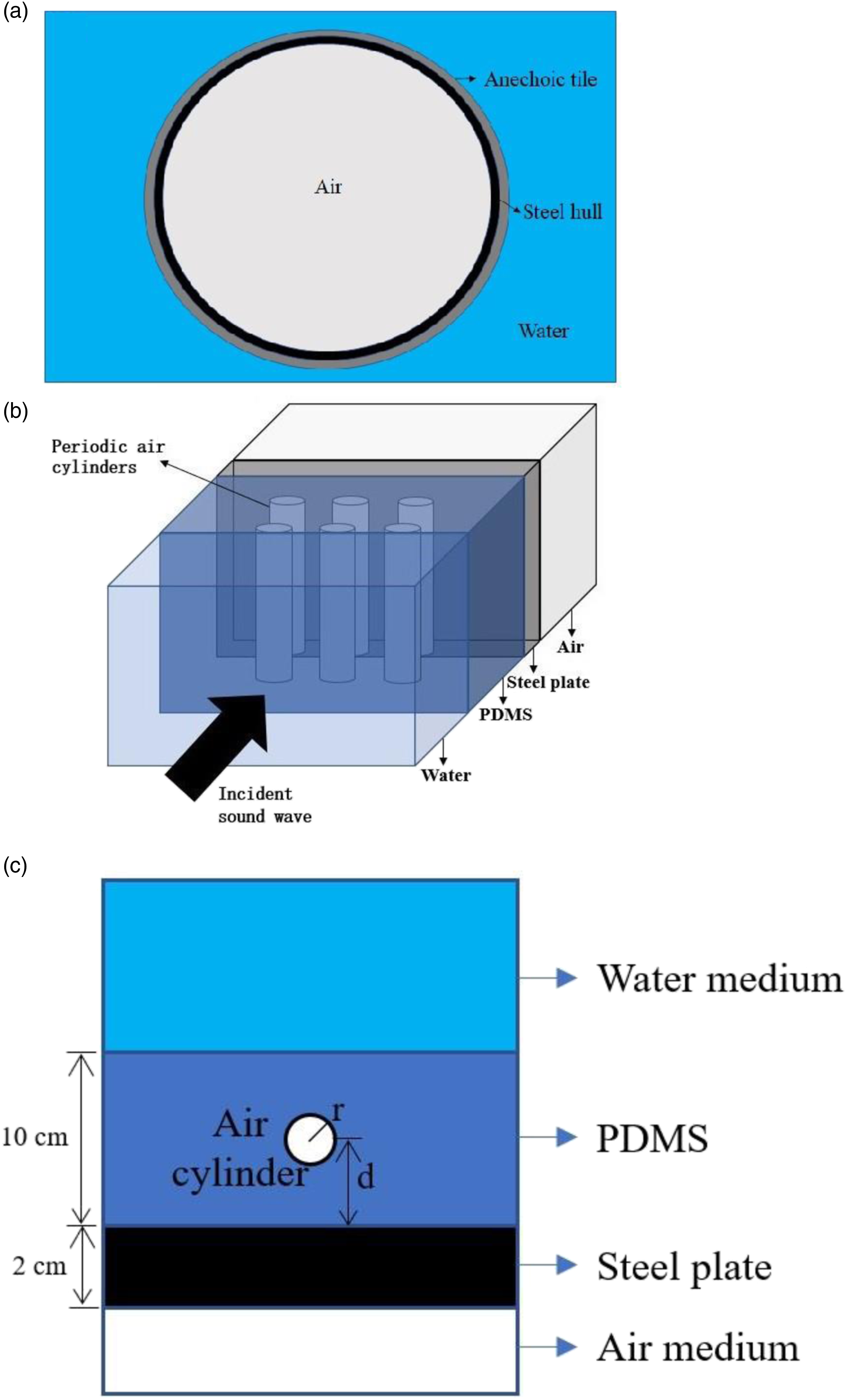
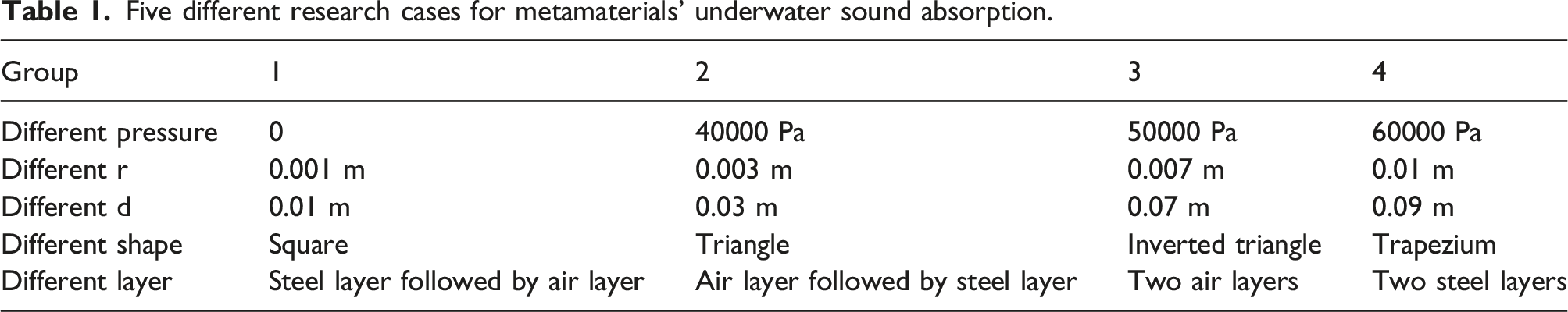
An acoustic-structure fully coupled FEM model will be developed from Ref. [16] to investigate the effect of hydrostatic pressure and optimize the structure to improve the sound absorption performance under various hydrostatic pressures. Some dimensions are given in Figure 1(c). r is the radius of the air cylinder, and d is the distance between the air cylinder and the steel backing. The following combinations of the structure are considered, and more details are given in Table 1. (i) One layer of air cylinders under different hydrostatic pressures; (ii) One layer of air cylinders under hydrostatic pressure with different radius (e.g., r); (iii) One layer of air cylinders under hydrostatic pressure with different distances to the steel backing (e.g., d); (iv) One layer of air cylinders under hydrostatic pressure with different shapes (e.g., square, triangle, inverted triangle, and trapezium); (v) Two layers of air and/or steel cylinders under various hydrostatic pressures. Five different research cases for metamaterials’ underwater sound absorption.
Numerical model and optimization method
FEM model
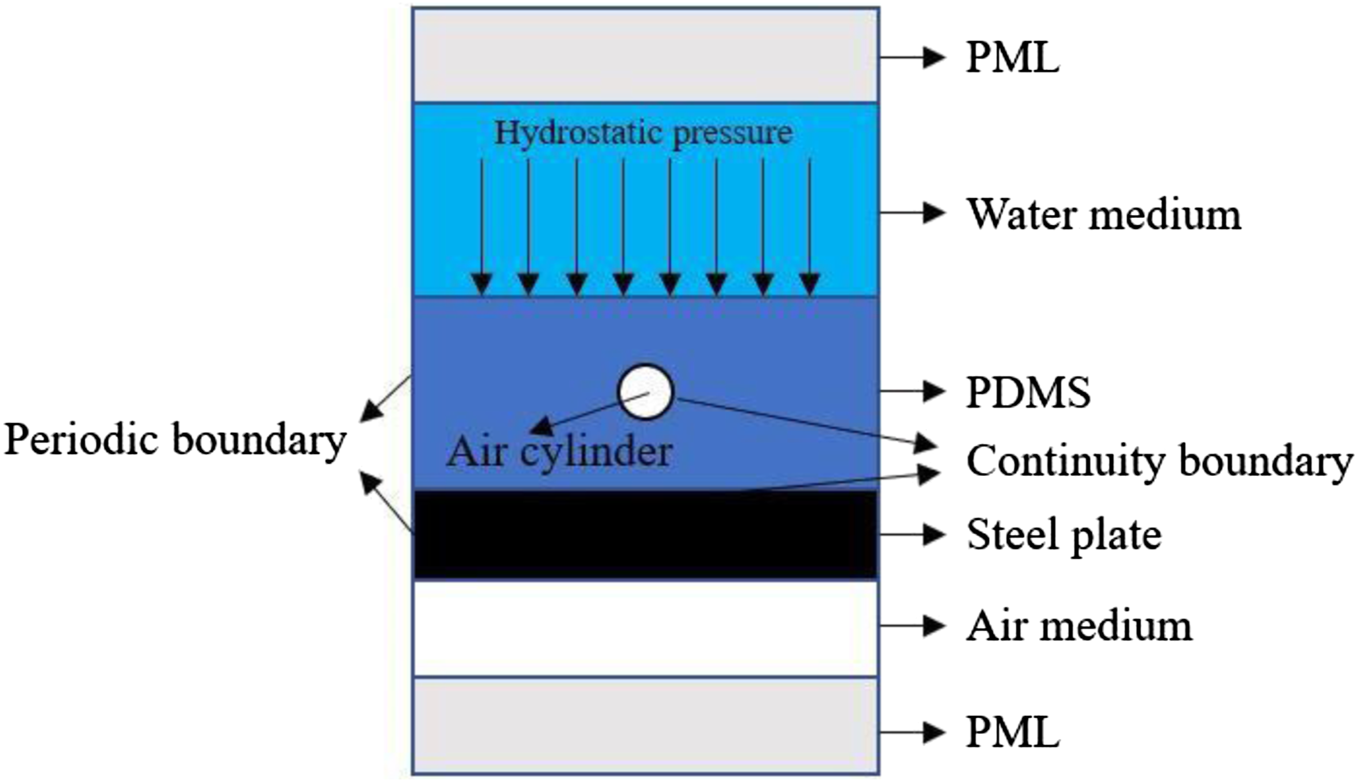
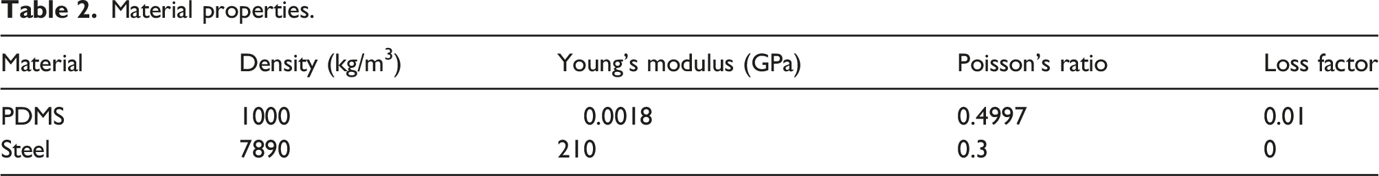
This study is about an underwater sound absorption metamaterial under various hydrostatic pressures. The numerical model is developed in the finite element software COMSOL Multiphysics. For a single model, the static pressure load or sound propagation can only be solved separately, and then transfer data from one model to another one. For this acoustic-structure fully coupled model, the two steps can be solved in one model. Firstly, the initial static model is built in the “Solid Mechanics” module, which calculates the structural deformation under different static pressure loads. Secondly, the sound absorption coefficient of the acoustic-structure fully coupled model is solved under the condition of plane wave incidence. It is worth noting that in this simulation scheme, the deformed sample for acoustic calculations can be automatically constructed based on the static deformation results without manual secondary modeling. The FEM numerical model is shown in Figure 2. The unit cell is an incident one-dimension plane wave from the fluid domain corresponding to water on the incidence side. The PDMS medium and the steel plate are modeled as solid domains. The water and the air media as acoustic fluid domains. Regarding the boundary conditions, acoustic structure boundary conditions are applied at the boundary of the solid and fluid domains to simulate the interaction between the solid and fluid media. Continuity boundary conditions are applied at the interface between the inclusion and rubber as well as between the steel backing plate and rubber. The interface between the void and rubber is applied with the free boundary condition. The boundary of the unit cell and fluid domains is applied with the periodic boundary condition to simulate the periodicity of the model in the direction normal to sound propagation. The outer boundaries of the fluid domains are applied with perfectly matched layer (PML) boundary conditions to model anechoic termination of the outgoing waves. The reflected and transmitted pressures are obtained at the interface between the solid and fluid media on the incidence and transmission sides, respectively. The governing wave equations for the coupled structure-acoustic problem are solved via COMSOL. The related settings about the material properties are given in the following section. The reflection coefficient is denoted by r
s
, and the transmission coefficient is denoted by t
s
, so that the absorption coefficient α can be obtained via the following equation Schematic diagrams of the acoustic-structure fully coupled model.
With the steel plate as backing, the transmission coefficient is almost 0, which can be ignored.
36
Therefore, the equation can be derived as the following
Model validation
Material properties.
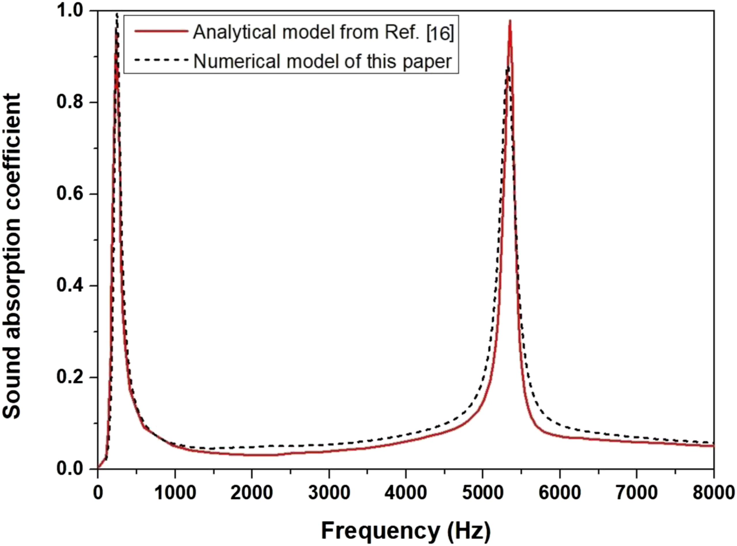
Sound absorption coefficients of a PDMS matrix containing a single layer of periodic air cylinders with a steel backing obtained analytically and numerically.
Optimization method
Before optimization, different configurations are investigated under hydrostatic pressures, including different cylinder radii, different distances between the air cylinder and the steel backing, different void shapes, and two layers of air and/or steel cylinders. Then the optimization method is used to further improve the underwater sound absorption stability at various hydrostatic pressures. The absorption coefficient is not a linear function of the structural or material parameters. Therefore, it is not practical to achieve an optimized absorption coefficient by an analysis method. Nelder–Mead algorithm has been proved to be a feasible method to optimize the structure of the sound absorption coatings and the material parameters.
32
In this study, the combination of the Nelder–Mead algorithm and FEM is developed for optimizing acoustic absorption. The FEM model can be viewed as an objective function, and the Nelder–Mead optimization module is applied to improve the objective function. The Nelder–Mead method is a gradient-free and general nonlinear constrained algorithm, which can be used to find a minimum for all in the search-space. The optimal design can be transformed from finding the optimal structure to searching the appropriate positions of N points for different variables. According to equation (3), the objective function is transformed from the maximum absorption coefficient to the minimum reflection coefficient. The mathematical equation is given below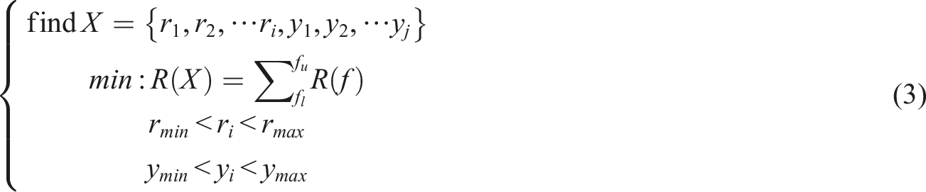
Results
Effect of hydrostatic pressure on sound absorption
As revealed in Figure 4, there are two sound absorption peaks around 200 Hz and 5300 Hz. When the hydrostatic pressure rises up to 4000 Pa, the sound absorption coefficient starts to decrease obviously in the whole frequency range. With the hydrostatic pressure increasing to 60,000 Pa, the sound absorption coefficient keeps decreasing. However, the reduction patterns of the two absorption peak values are quite different. The first absorption peak almost disappears at 60,000 Pa, while the second absorption peak only decreases slightly. It is also worth noting that the first absorption peak shifts to lower frequency, while the second absorption peak shifts to higher frequency. The difference can be attributed to the corresponding mechanisms behind them. The first absorption peak can be explained by a simplified spring-mass physical model, where the spring is provided by the air cylinder and the steel backing with the PDMS layer under the air cylinder acts as the mass.
17
The second absorption peak is due to the scattering effect between the air cylinder and the steel backing. To further understand the effect of the hydrostatic pressure, the deformations under different hydrostatic pressures are investigated below. Sound absorption coefficient a PDMS matrix containing a single layer of periodic air cylinders at 0 Pa, 40,000 Pa, 50,000 Pa, and 60,000 Pa.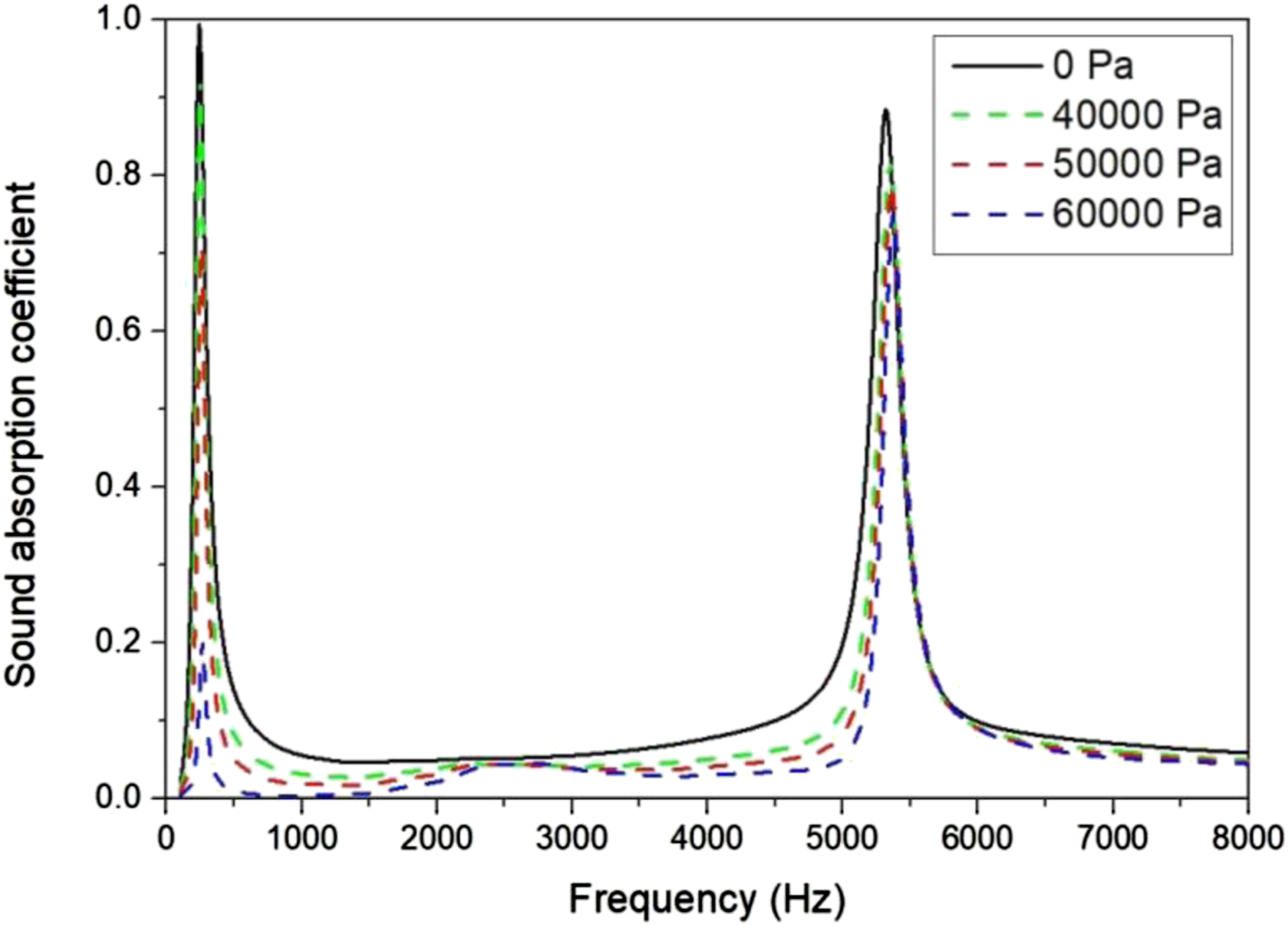
Figure 5 presents deformation plots under different hydrostatic pressures of 0 Pa, 40,000 Pa, 50,000 pa, and 60,000 Pa. The deformation is 0 under atmospheric pressure. With the increase of hydrostatic pressure, the corresponding compression deformation value improves from 0 m to 2.0 × 10⁻⁸ m, 2.5 × 10⁻⁸ m, and 3.0 × 10⁻⁸ m. The deformation mainly occurs around and above the air cylinder. While the region between the air cylinder and the steel backing is almost free from compression. The maximum deformation appears on the top of the air cylinder, which means that the air cylinder is directly compressed by the hydrostatic pressure. Therefore, the spring in the spring-mass system is severely limited. This can explain that the first absorption peak is more easily affected by hydrostatic pressure compared with the second absorption peak. Therefore, resonance or local resonance sound absorption materials are sensitive to hydrostatic pressure because the reasoner will be limited under compression. Especially for air reasoners, the deformation can further degrade the sound absorption performance. Deformation (in meter) of a PDMS matrix containing a single layer of periodic air cylinders under different hydrostatic pressure: (a) 0 Pa, (b) 40,000 Pa, (c) 50,000 Pa, and (d) 60,000 Pa.
Comparisons under various r
The size of the air cylinder has significant effect on the sound absorption performance under various hydrostatic pressures. Figure 6 shows the sound absorption coefficient of samples with air cylinders of different radii. The sample with small air cylinders (e.g., r = 0.001 m) has high absorption coefficient in a broadband and a higher average magnitude. And with the increase of the radius, the first absorption peak shifts to the low frequency. This can be explained that the smaller air cylinder can be viewed as a more rigid spring, which has high resonance frequency. In contrast, the second absorption peak shifts to the high frequency. However, the smaller air cylinder is more easily impacted by various hydrostatic pressures. As indicated in Figure 6(a), the sound absorption coefficient decreases significantly under various hydrostatic pressures. In contrast, the sample with big air cylinders (e.g., r = 0.01 m) has a narrow band but can stand higher hydrostatic pressure. The results presented here highlight the independent effects of the air cylinders on the first and second absorption peaks, whereby the size of the radius of the air cylinder mainly affects the frequency and magnitude of the first absorption peak associated with mass-spring resonance. Sound absorption coefficient of a PDMS matrix containing a single layer of periodic air cylinders with different radii (a) 0.001 m, (b) 0.003 m, (c) 0.007 m, and (d) 0.01 m. The results are obtained under 0 Pa (solid lines) and 50,000 Pa (dash lines).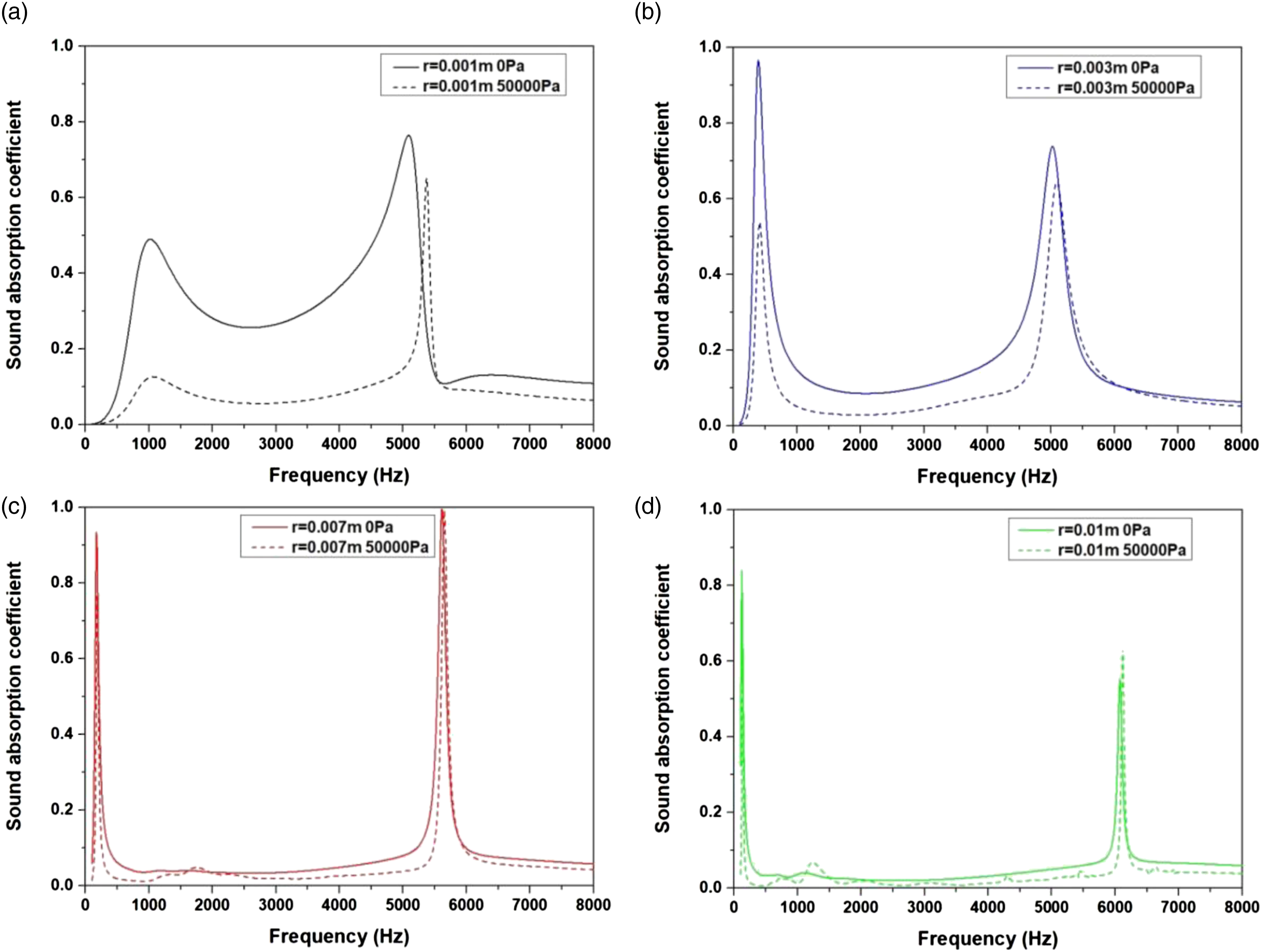
The deformation of air cylinders with different radii is presented in Figure 7. The deformation of the sample with small air cylinders (e.g., r = 0.001 m) in Figure 7(a) is much lower than that of the sample with big air cylinders (e.g., r = 0.01 m) in Figure 7(b). However, the small air cylinder is more easily compressed under various hydrostatic pressures because its sound absorption coefficient declines more as shown in Figure 6(a). Though the sample with big air cylinders suffers from larger deformation, large void areas remain as shown in Figure 6(d). Therefore, the sound absorption performance of the sample with big air cylinders decreases less. It can be concluded that the sample with small air cylinders has a wide sound absorption peak, but is more easily compressed under various hydrostatic pressure. While the sample with big air cylinders has a narrow sound absorption peak, it can stand high hydrostatic pressure. Deformation (in meter) of a PDMS matrix containing a single layer of periodic air cylinders with different radii (a) 0.001 m, (b) 0.003 m, (c) 0.007 m, and (d) 0.01 m.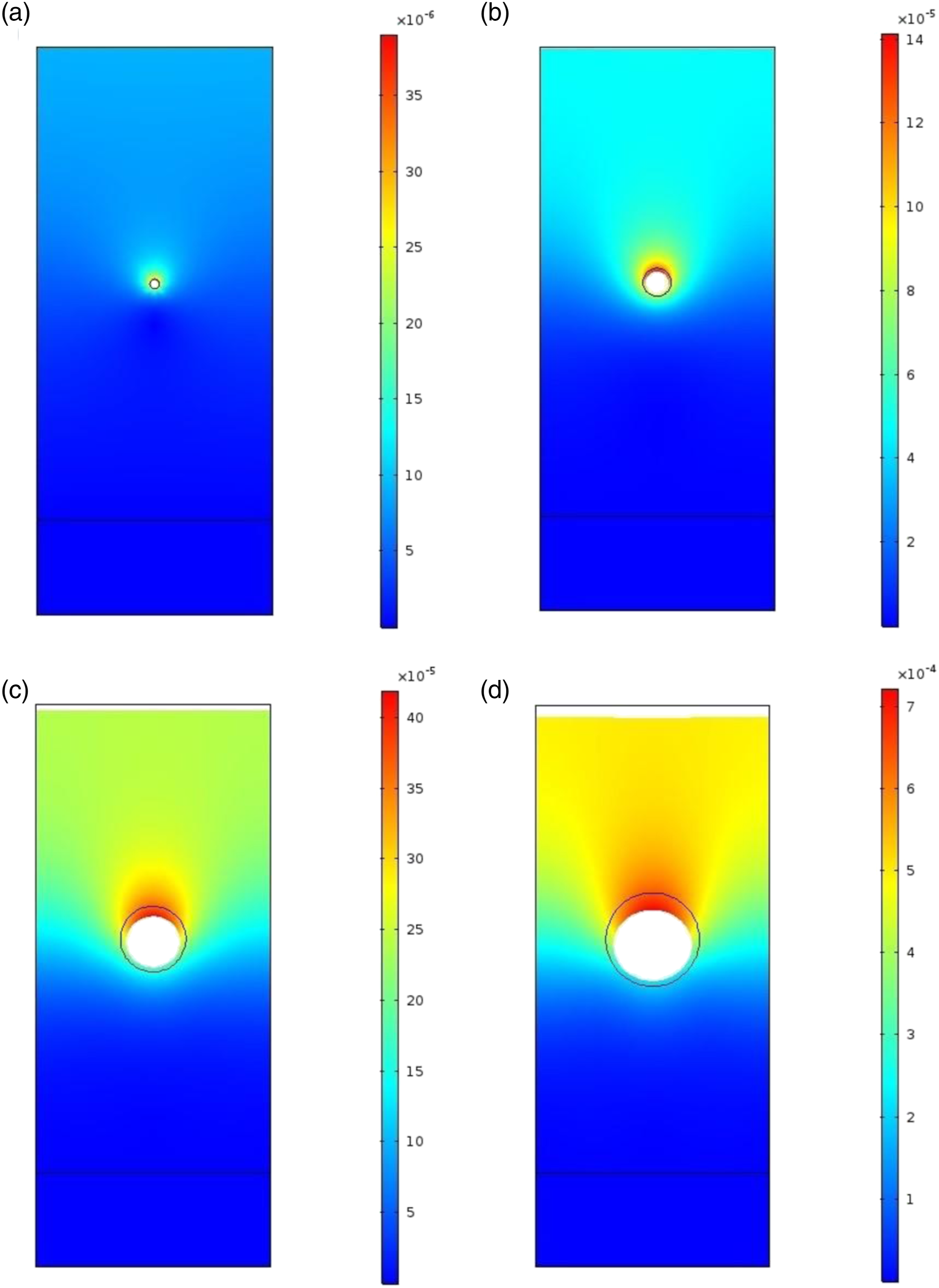
Comparisons under various d
The results in Figure 8(a)–(d) show that the distance between the air cylinders and the steel backing has a significant effect on the second absorption peak. With the increase of the distance between the air cylinders and the steel backing, the second absorption peak shifts to low frequency. This can exactly explain that the air cylinder moves to the steel plate backing under high hydrostatic pressure, so the second absorption peak shifts to high frequency as mentioned above. The results also confirm that the frequency of high absorption coefficient can be achieved by changing the distance. To some extent, the result proves that air cylinders with the proper distance between the steel backing should be able to transform a perfect reflector (with low absorption coefficient) into a perfect absorber (with high absorption coefficient). A simplified analytical model was built to explain this phenomenon by considering only the interference between the direct reflection from the void layer, and the multiple reflections between the layer and the reflector.
20
The performance under various hydrostatic pressures illustrates that the sound absorption coefficient will decrease more when the air cylinder is too close to the water side (e.g., d = 0.09 m) as shown in Figure 8(d). Sound absorption coefficient of a PDMS matrix containing a single layer of periodic air cylinders with different distances to the steel backing (a) 0.01 m, (b) 0.03 m, (c) 0.07 m, and (d) 0.09 m. The results are obtained under 0 Pa (solid lines) and 50,000 Pa (dash lines).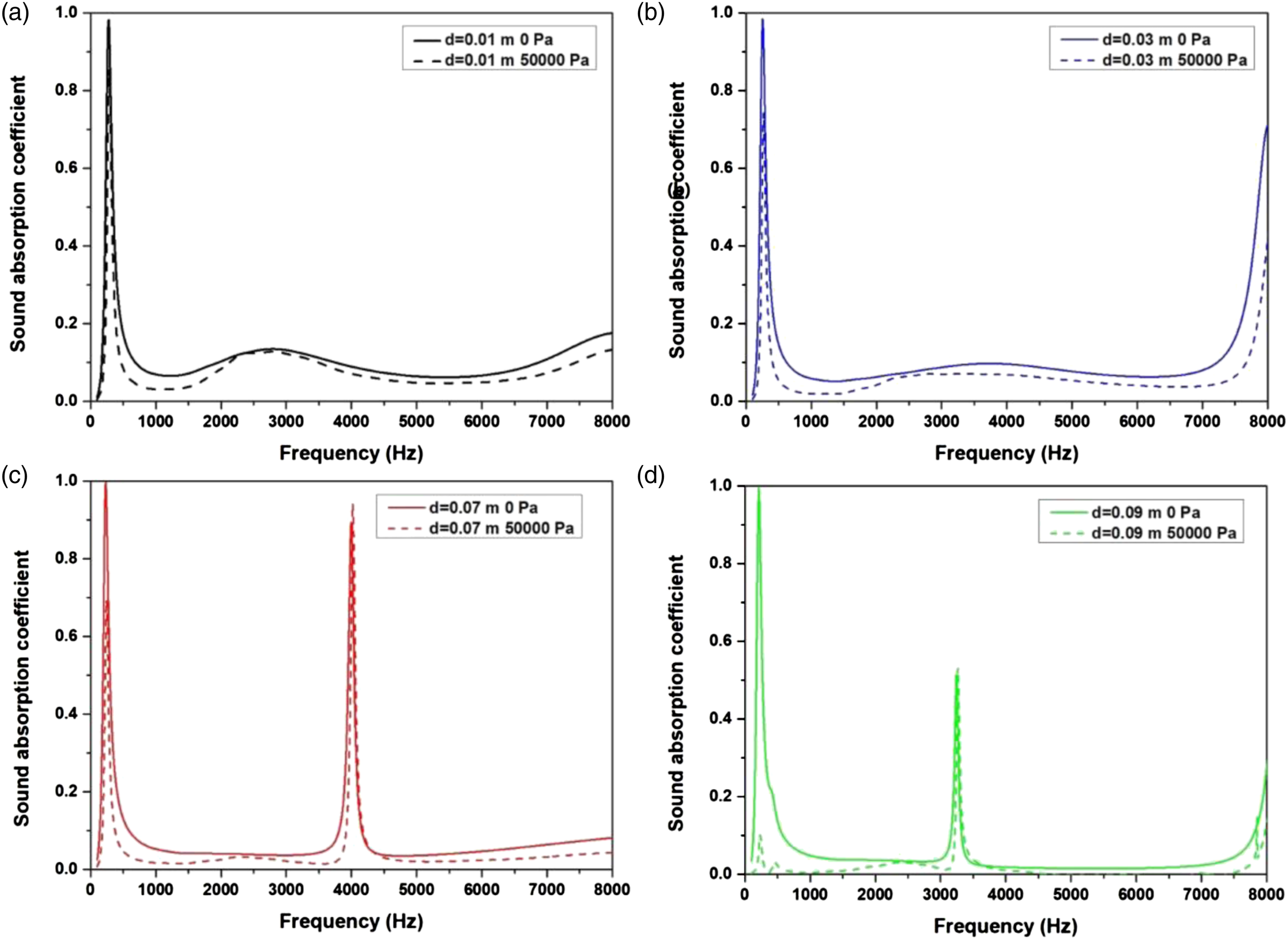
The effect of the distance between the air cylinders and the steel backing on the deformation varies. If the air cylinders are in the middle range of the PDMS matrix, the deformation almost does not change as shown in Figure 9(b) and (c). If the air cylinder is too close to the water side, it is easier to be compressed under high hydrostatic pressure as shown in Figure 9(d). In general, the underwater sound absorption performance at high hydrostatic pressure cannot be maintained by changing the distance between the air cylinders and the steel backing. However, it can be concluded that the air cylinder cannot be located close to the water side, otherwise, the air cylinder will be directly exposed to high hydrostatic pressure and suffer from obvious deformation. Deformation (in meter) of a PDMS matrix containing a single layer of periodic air cylinders with different distances to the steel backing (a) 0.01 m, (b) 0.03 m, (c) 0.07 m, and (d) 0.09 m.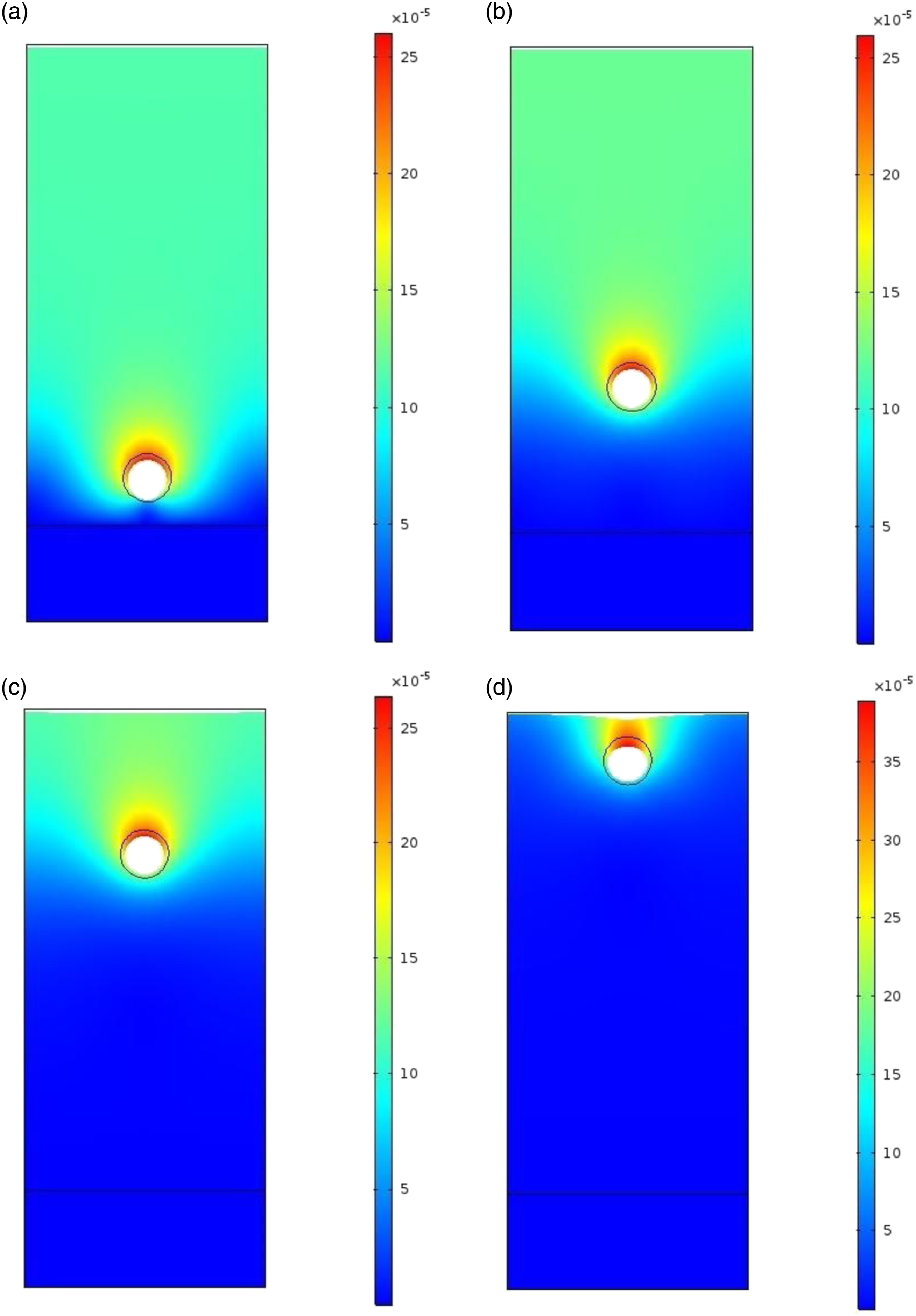
Comparisons under various void shapes
The effect of the void shape is also investigated, including square, triangle, inverted triangle, and trapezium. The sound absorption coefficient of the metamaterials embedded air cylinders with different shapes is shown in Figure 10. There are two absorption peaks in all results, and the frequency range of the corresponding peak is close. Compared with the circle air cylinder, the other four different shapes have high absorption coefficient values at the second peak. For square and trapezium air cylinders, their sound absorption performances at both atmospheric and high hydrostatic pressures are in the same trend as shown in Figure 10(a) and (d). Their first absorption peaks reduce more than that of the circle air cylinders. The samples embedded triangle and inverted triangle air cylinders have quite a similar sound absorption performance, especially at the second absorption peak as shown in Figure 10(b) and (c). And their first absorption peaks both decrease substantially under high hydrostatic pressure, while some frequencies at the second absorption peaks even have obviously improved sound absorption performance. Sound absorption coefficient of a PDMS matrix containing a single layer of periodic air cylinders with different shapes (a) square, (b) triangle, (c) inverted triangle, and (d) trapezium. The results are obtained under 0 Pa (solid lines) and 50,000 Pa (dash lines).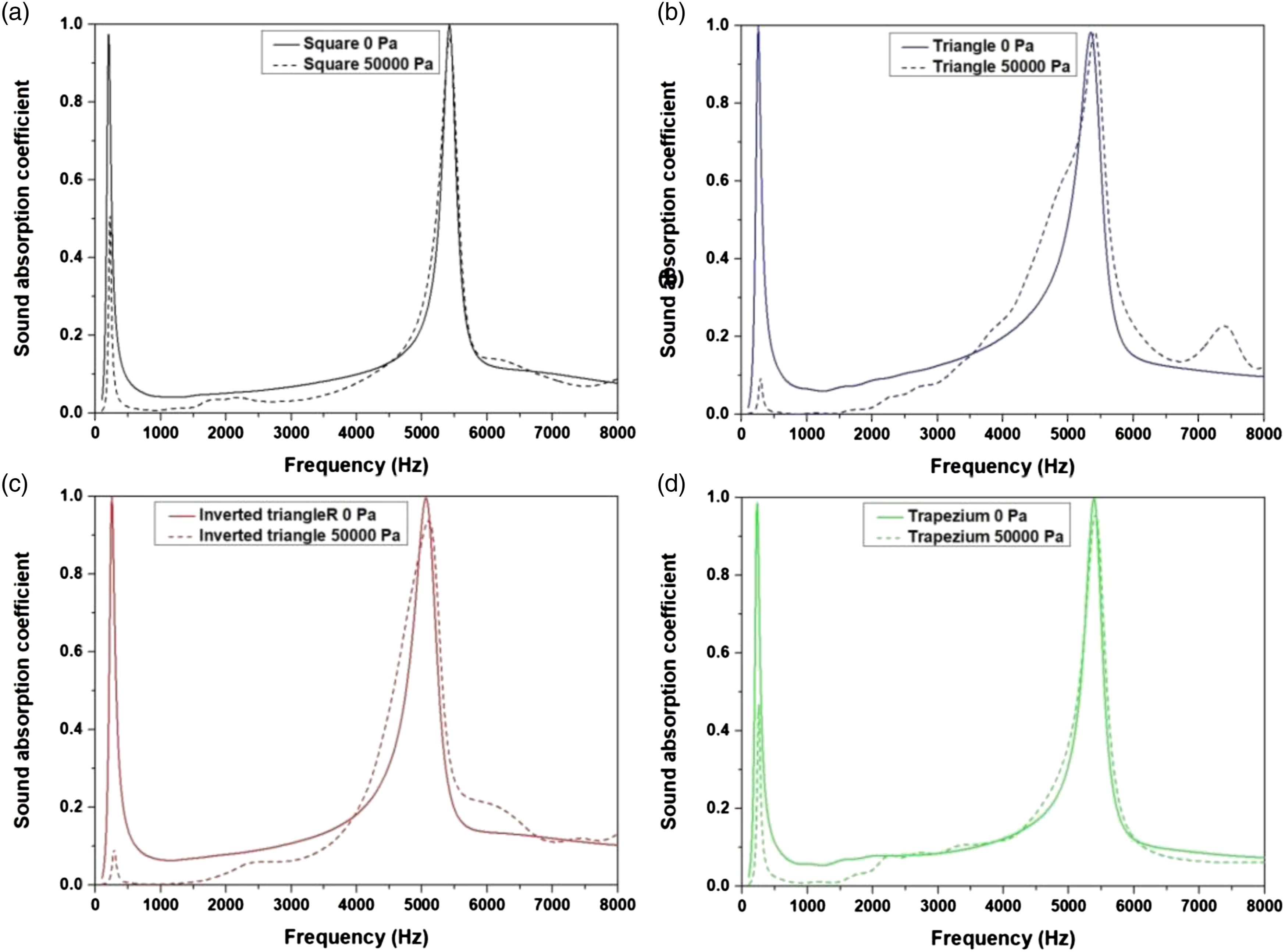
The deformation plots are displayed in Figure 11. The total displacement is the sum of x and y component displacements. Therefore, in terms of total displacement, these voids have advantages in different regions. Deformation (in meter) of a PDMS matrix containing a single layer of periodic air cylinders with different shapes (a) square, (b) triangle, (c) inverted triangle, and (d) trapezium.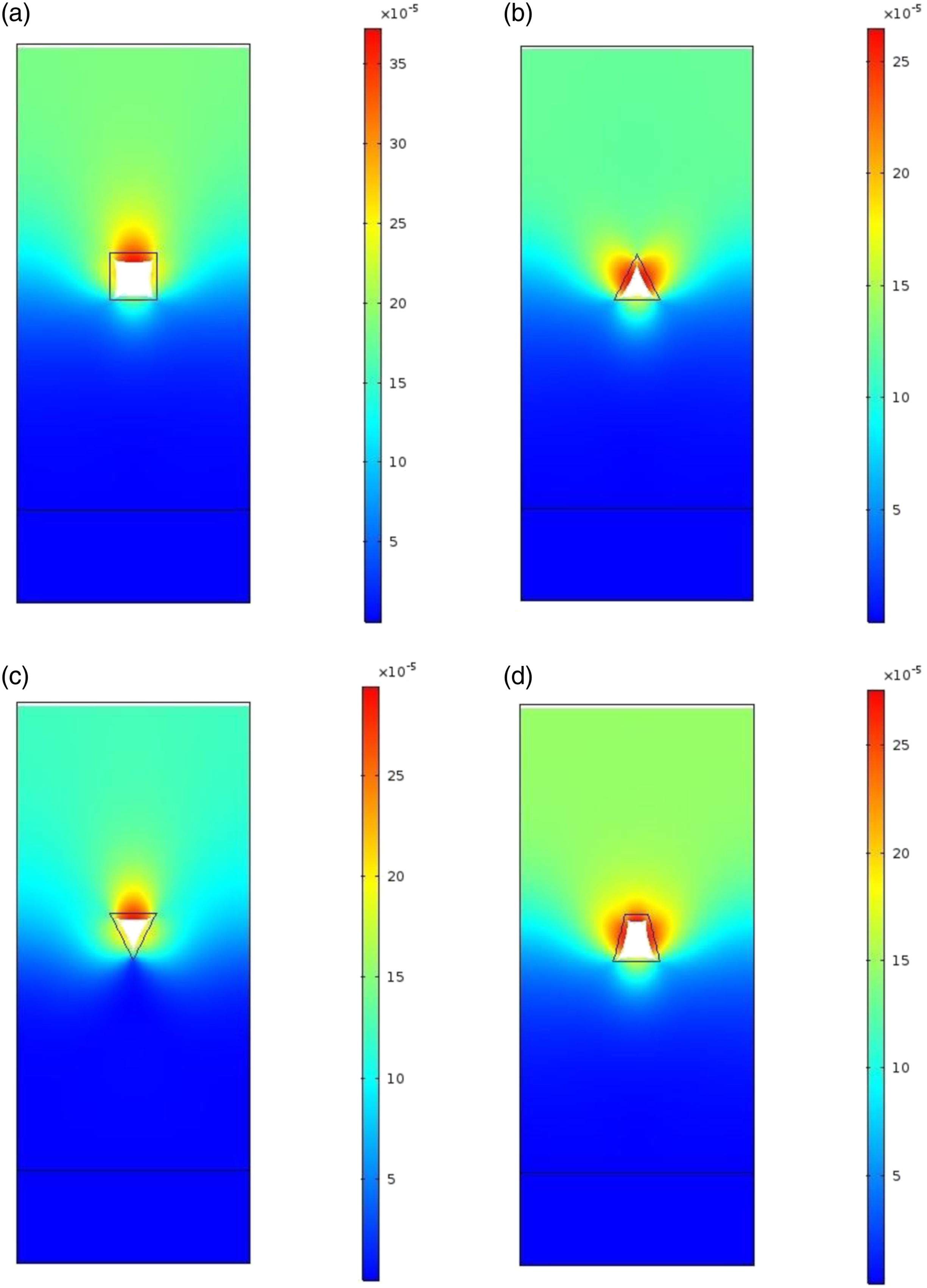
The maximum deformation of the square air cylinder is the largest, which is 3.5 × 10⁻⁵ m, while the others are all 2.5 × 10⁻⁵ m. For the triangle air cylinder, the maximum deformation occurs on the two side edges of the triangle as illustrated in Figure 11(b). For comparison purposes, the maximum deformation of the inverted triangle occurs on the top edge as shown in Figure 11(c). It is worth noting that the deformation at the bottom of the inverted triangle void is the lowest among them. Interestingly, the maximum deformation of the trapezium occurs on the top and side edges from Figure 11(d). In general, it can be concluded that the surface without solid support underneath will suffer more deformation. Changing the shape of the air cylinder is not an effective way to improve underwater sound absorption stability under various hydrostatic pressures.
Comparisons under various inclusions
Two layers of different inclusions are embedded into PDMS matrix material. Figure 12 shows the sound absorption coefficient of the metamaterial for the four cases of air and/or steel cylinders in PDMS with steel backing. For the PDMS matrix comprising a layer of steel cylinders followed by a layer of air cylinders, there are still two absorption peaks, but the second absorption peak shifts to high frequency. Under hydrostatic pressure of 50,000 Pa, the sound absorption coefficient still declines. The same conclusion can be made to the PDMS matrix which comprises a layer of air cylinders followed by a layer of steel cylinders. Sound absorption coefficient of a PDMS matrix comprising (a) a layer of steel cylinders followed by a layer of air cylinders (black), (b) a layer of air cylinders followed by a layer of steel cylinders (blue), (c) two layers of air cylinder (red), (d) two layers of steel cylinders (green lines) in PDMS. The results are obtained under 0 Pa (solid lines) and 50,000 Pa (dash lines). The results are obtained under 0 Pa (solid lines) and 50,000 Pa (dash lines).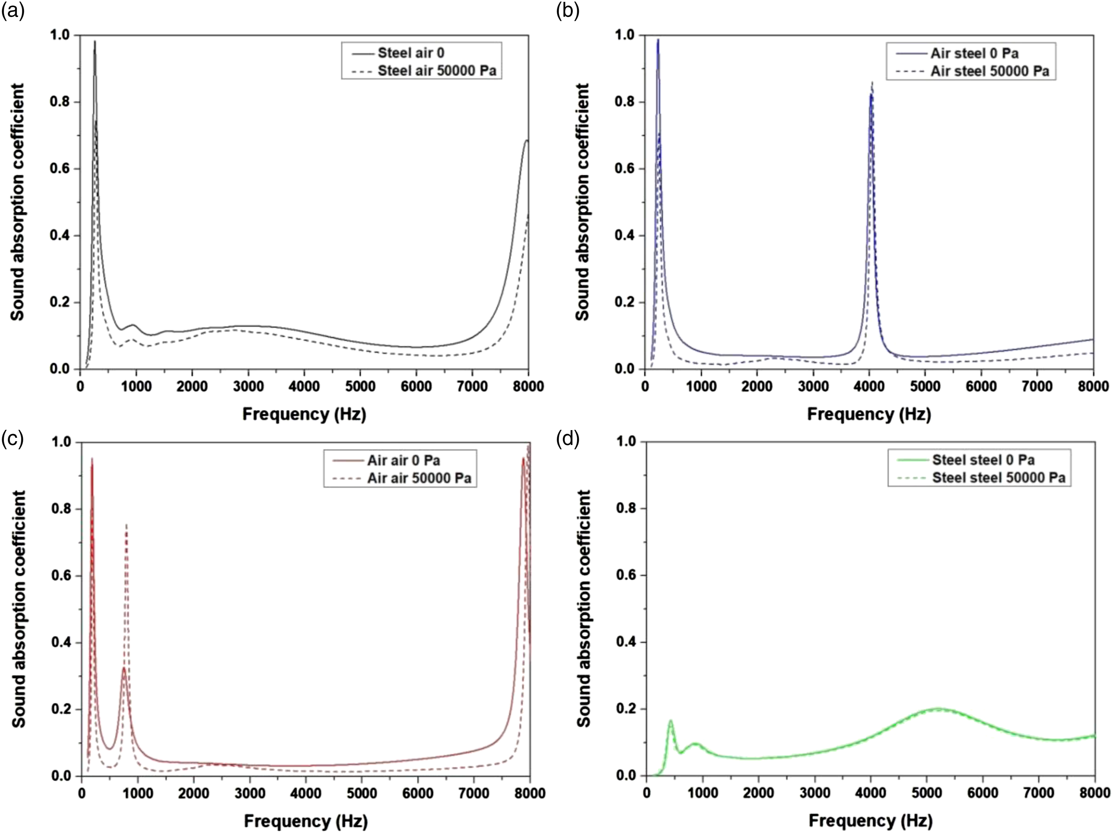
For two layers of air cylinders, three absorption peaks appear in the frequency range. Under various hydrostatic pressures, these three absorption peaks do not decline. The second absorption peak even rises. In contrast, for two layers of steel cylinders, their sound absorption coefficient is not affected by hydrostatic pressure, but the sound absorption performance is the worst. There are no obvious absorption peaks for two layers of steel cylinders.
From the deformation plots in Figure 13, some interesting findings can be observed. The steel cylinder can be viewed as a solid, so the deformations of the PDMS matrix comprising a layer of steel cylinders followed by a layer of air cylinders, and a layer of air cylinders followed by a layer of steel cylinders as shown in Figure 13(a) and (b) are almost the same as one layer of air cylinder as shown in Figure 9(b) and (c). For two layers of air cylinders, the top layer of air cylinders endures most of the compression, so the second layer of air cylinders can be protected from large deformation. Therefore, the sound absorption of the sample with two layers of air cylinders has the most stable performance under various hydrostatic pressures. In another study, it was also found that the double-layer holes are more effective on sound absorption with increased global maximum power absorption and effective frequency ranges.
37
For two layers of steel cylinders, the deformation is the smallest since the steel cylinders cannot be compressed.
38
However, the issue is that steel is not a good sound scatter as the air. Deformation (in meter) of a PDMS matrix comprising (a) a layer of steel cylinders followed by a layer of air cylinders, (b) a layer of air cylinders followed by a layer of steel cylinders, (c) two layers of air cylinders in rubber, and (d) two layers of steel cylinders in rubber.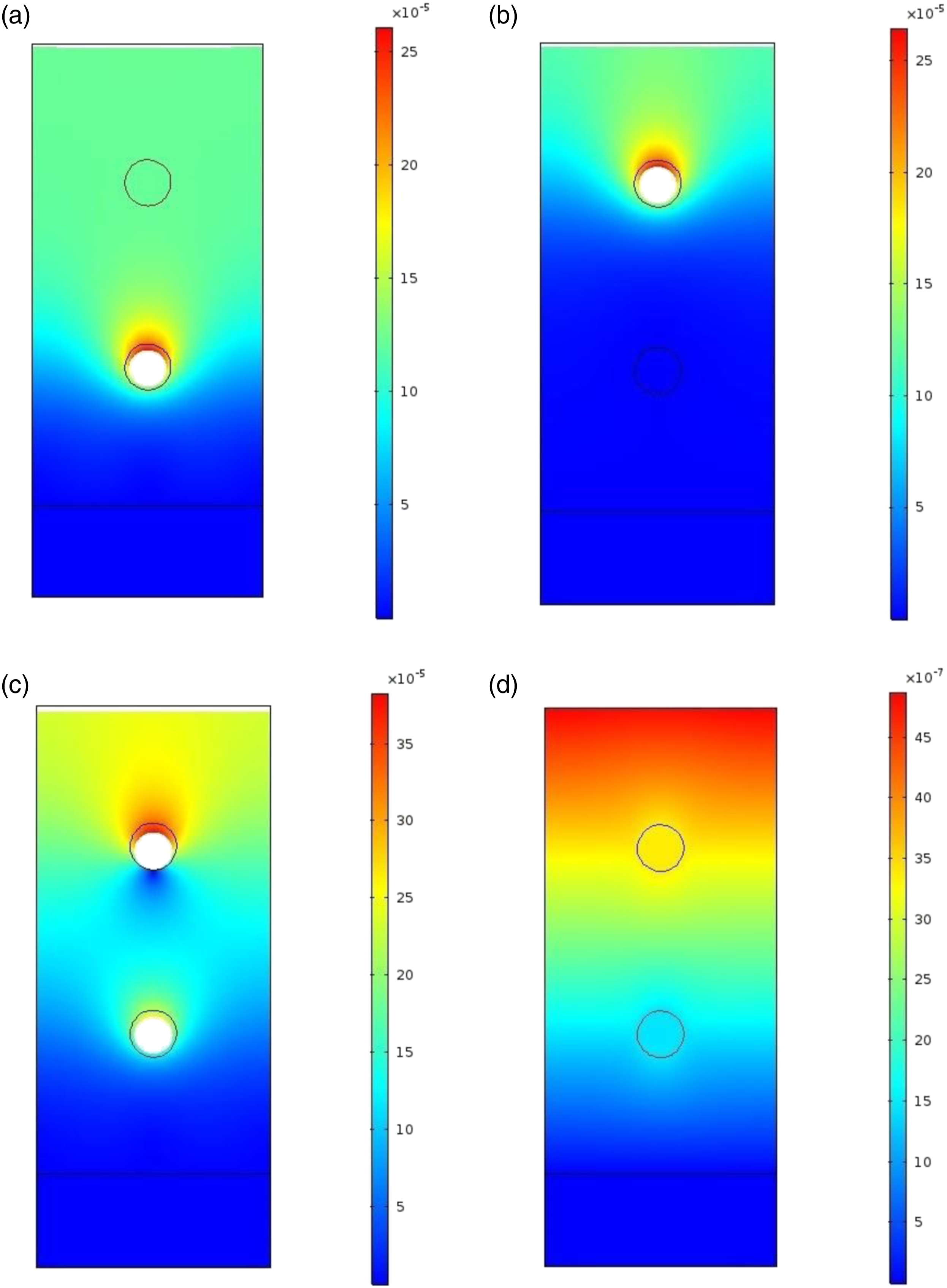
Optimized structural parameters
Since the two layers of air cylinders are the most stable structure under various hydrostatic pressures, the Nelder–Mead algorithm is used to optimize the structure with two layers of air cylinders. According to the optimization method, the optimized structural parameters are the radii and vertical locations of the two air cylinders. The optimization results are given in Figure 14. Figure 14 shows the optimal structure and the deformation under 50,000 Pa. The radius of the first layer air cylinder decreases from 0.005 m to 0.00,171 m, while the radius of the second layer air cylinder increases from 0.005 m to 0.00,622 m. Compared with the deformation in Figure 13(c), the value of the maximum deformation is almost the same, but the occurred area moves from the top layer to the bottom layer. As analyzed from Figure 7, air cylinders with larger radius suffer from larger deformation. In the case of two-layer air cylinders with the same size, the maximum deformation will occur on the top layer, but the maximum deformation can be shifted to the bottom layer by reducing the size of the top layer air cylinder. Further, the deformation of the top layer air cylinder can be reduced by adding a bottom layer air cylinder with larger radius. Optimal results of a PDMS matrix comprising two layers of air cylinders under 50,000 Pa: (a) deformation (in meter), (b) sound absorption coefficient.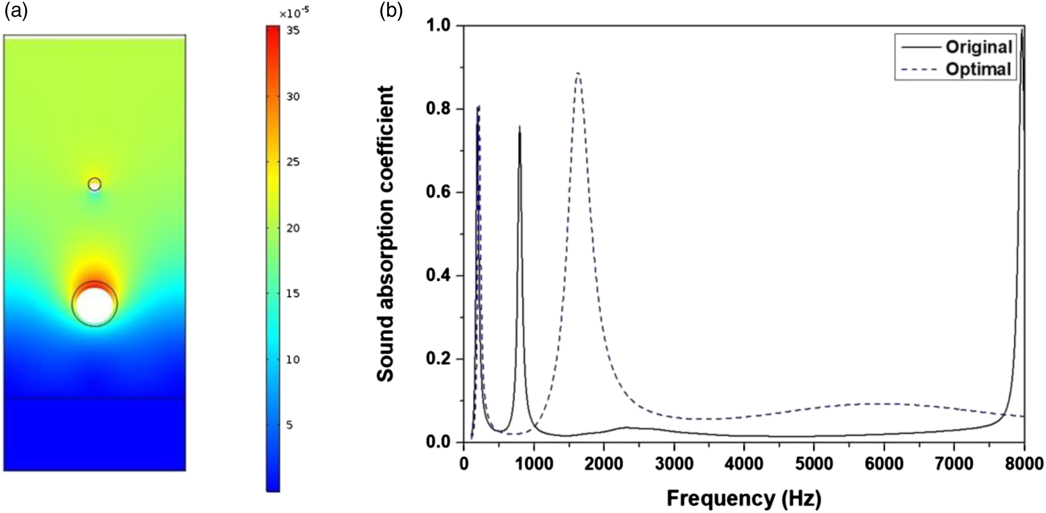
In terms of the sound absorption performance, the first absorption peak of the optimal structure remains unchanged, but the second absorption peak of the optimal structure becomes much wider. The absorption coefficient in the frequency range of 1000 Hz–7700 Hz is all improved. Therefore, the absorption of the optimal structure after overall optimization is obviously better than that of the original structure in the considered frequency region.
It can be concluded that the sound absorption performance of the model under various hydrostatic pressures can be improved by combining with the Nelder–Mead algorithm and the acoustic-structure fully coupled FEM. However, it should be mentioned that the structure with the best performance at atmospheric pressure may not perform best at high hydrostatic pressure. Therefore, it is important to design structures under various hydrostatic pressures for those applications under hydrostatic pressure. For various pressures, each pressure should be considered. In the future work, experimental studies about the effect of various hydrostatic pressures on material properties and sound absorption performance will be carried out.
Discussion and conclusions
The underwater sound absorption performance of metamaterials with periodic cylinders at various hydrostatic pressures has been investigated. An acoustic-structure fully coupled model is developed, which can overcome the challenges for the single-model approach to simulate hydrostatic pressure load and acoustic calculation separately. Employing this model, the deformation and sound propagation calculations can be solved simultaneously. The effect of hydrostatic pressure on the acoustic performance is investigated and overcome. The results show that the sample with small cylinders has high absorption coefficient in a broadband and a higher average magnitude at atmospheric pressure, but it is more easily compressed under high hydrostatic pressure. By changing the distance between the air cylinder and the steel backing, it is found that the distance mainly affects the second absorption peak. If the air cylinder is too shallow in PDMS, the air cylinder is easier to be compressed under high hydrostatic pressure. It is also not efficient to improve the pressure resistance by changing the shape of the air cylinder. Metamaterials with two layers of air cylinders have the best sound absorption performance under various hydrostatic pressures because the top layer of air cylinders can absorb the main deformation. Further, the Nelder–Mead algorithm is used to optimize the metamaterials with two layers of air cylinders. The underwater sound absorption is significantly improved after the optimization. This proposed Nelder–Mead algorithm with the acoustic-structure fully coupled FEM method can be used to guide the design and optimization of underwater sound absorption metamaterials at various hydrostatic pressures.
Footnotes
Declaration of conflicting interests
The author(s) declared no potential conflicts of interest with respect to the research, authorship, and/or publication of this article.
Funding
The author(s) disclosed receipt of the following financial support for the research, authorship, and/or publication of this article: This work was supported by the Scientific Research Start Foundation of Jiangsu University (No.5501120017), the National Natural Science Foundation of China (No. 52205197 and 51905468), the Natural Science Foundation of Jiangsu Province (No. BK20190916 and BK20220551) and ‘Blue Project’ of Yangzhou University.