
Abstract
The fractional-order differential theory is applied in the hydraulic inerter to describe its mechanical characteristic, a semi-active fractional-order (SA-FO) inerter based on the hydraulic inerter is proposed and used in the vehicle suspension to constitute the semi-active fractional-order inerter-based (SA-FOIB) suspension, which consists of two adjustable inertances. According to the mechanical characteristic of the inerter, the acceleration-velocity switch (AVS) control strategy is proposed to adjust the inertance of the SA-FO inerter. The dynamic model of the SA-FOIB suspension with AVS control is established, its dynamic response under road harmonic excitation is obtained using the averaging method, the dynamic performance under road harmonic and random excitations is analyzed and evaluated by the vehicle body acceleration, suspension dynamic deflection and wheel dynamic load, the optimized structural parameters are obtained using the genetic algorithm optimization method. The results show that for road harmonic excitation, the SA-FOIB suspension can further enhance the high-frequency dynamic performance of the passive fractional-order inerter-based (P-FOIB) suspension, which the high-frequency resonance peaks of the dynamic performance indices are smaller. For road random excitation, the SA-FOIB suspension can decrease the root-mean-square (RMS) values of the suspension dynamic deflection and wheel dynamic load compared with the P-FOIB suspension, while increases the RMS value of the vehicle body acceleration. The optimized SA-FOIB suspension further improves the dynamic performance of the suspension dynamic deflection and wheel dynamic load, which the corresponding RMS values are smaller than the unoptimized SA-FOIB suspension, while deteriorates the vehicle body acceleration.
Keywords
Introduction
The suspension is one of the most significant structure for a vehicle, it isolates and reduces the vibration transmitted from the road to the vehicle body, which not only supports the vehicle body, but also affects the vehicle dynamics.1–4 Thus, the suspension research is an indispensable part in the vehicle dynamics analysis. In 2002, Smith 5 firstly proposed a new vibration attenuation device, inerter, it is a device with two terminals, the produced equal force applied on the two terminals is proportional to the relative acceleration between them, the corresponding proportional coefficient is called inertance and is measured in kilogram.6,7 The generation of inerter leads to the birth of the inerter-based suspension, which consists of three elements: inerter, spring and damper. Compared with the traditional two-element suspension composed of spring and damper, the inerter-based suspension has a variety of structural arrangements, which can further improve the vehicle dynamics.8,9 According to the inertial force realization, the inerter can be divided into mechanical, hydraulic and electromagnetic ones, 10 it can be also divided into passive and semi-active inerters based on whether the inertance can be changed or not. 11 The appearance of semi-active inerter greatly promotes the development of inerter-based suspension.
Similar to the traditional suspension, the inerter-based suspension can be divided into passive, semi-active and active ones. 12 The passive inerter-based suspension has the advantages of high reliability, easy implementation and low cost, no additional energy is required, but its improvement in vehicle dynamics is limited.13,14 The active inerter-based suspension can adjust the force acting on the unsprung and sprung masses in real time, it has the best vibration attenuation effect in the three suspensions, but it needs a large amount of additional energy. 15 The semi-active inerter-based suspension enhances the vehicle dynamics by adjusting the structural parameters, such as damping or inertance. Since there is no actuator, it greatly reduces the own energy loss and is a suspension with better comprehensive performance. Zhang et al. 16 applied the semi-active damper in the inerter-based suspension and designed the skyhook, groundhook and hybrid control methods, which further improves the dynamic performance than the passive one. Chen et al. 17 constructed a semi-active inerter-based suspension with both semi-active inerter and damper, and presented a force-tracking approach to adjust the inertance and damping. Hu et al. 18 and Zhang et al. 19 proposed an adjustable semi-active inerter and used it in the inerter-based suspension to improve the vehicle ride comfort. Wang et al. 20 proposed a relative-acceleration-relative-velocity control method to adjust the inertance of the semi-active inerter and enhanced the vehicle dynamics. Yang et al. 21 presented a semi-active hydro-pneumatic inerter-based suspension based on the model predictive control method, and yield a better low-frequency dynamic performance. Zhu et al. 22 designed a semi-active dual-chamber hydro-pneumatic inerter-based suspension and used the linear quadratic Gaussian controller to match its nonlinear characteristics, which improves the vehicle smoothness and handling stability. Overall, the semi-active inerter-based suspension can further obtain a better vehicle dynamic performance than the passive one.
The hydraulic inerter has the advantages of simple structure, easy adjustment of inertance and large bearing capacity, compared with the mechanical inerter. Some scholars have shown that the fluid of hydraulic inerter is similar to multi-phase media, and it is not accurate to describe the mechanical characteristic of hydraulic inerter by integer-order differential theory. 23 Westerlund 24 used the fractional-order differential theory to describe the multi-phase media system for hydraulic system modeling, which is more accurate than the integer-order differential theory modeling. The fractional-order calculus has a wide range of order values, which can be selected between real numbers and imaginary numbers, and can be considered as an extension of integer-order calculus. The fractional-order calculus has memory property and changeable continuity due to its own characteristic, and can better describe the dependent process of the historical development of the dynamic system. Compared with the integer-order calculus, the fractional-order calculus can describe the dynamic characteristic of the hydraulic system more accurately by using the fractional order.
In the fractional-order differential theory field, Caputo and Maindardi 25 established a new memory dissipation model based on the fractional-order differential theory, and proved the accuracy of the model by verifying the dissipation curves of various materials. Vinagre et al. 26 introduced the fractional-order differential theory into the model reference adaptive control and shown the advantage of fractional-order adaptive control. Bagley and Torviky 27 studied the mechanical characteristic of viscoelastic damping structure using fractional-order differential theory, which effectively improves the model accuracy. Zamani et al. 28 designed a fractional-order proportional-integral-derivative controller to realize semi-active control of base-isolated structure under far-field and near-field seismic excitation. You et al. 29 analyzed the dynamic performance and conducted the parameter design of the fractional-order traditional two-element suspension, which reduces the vehicle body vertical acceleration. Chen et al. 30 investigated the dynamic characteristic of one degree-of-freedom (DOF) vibration isolator with both fractional-order inerter and damper, which reduces the natural frequency and improves the vibration isolation performance of the system. In summary, it is more reasonable to use fractional-order differential theory to describe the mechanical characteristic of the hydraulic system than the integer-order differential theory, which proves the reliability of fractional-order dynamic model used in the hydraulic system. In addition, the fractional-order inerter and damper can be used to further improve the dynamic system performance.
In this paper, the fractional-order differential theory is applied in the hydraulic inerter to describe its mechanical characteristic, the semi-active fractional-order (SA-FO) inerter based on the hydraulic inerter is proposed and consists of two adjustable inertances. The order of the SA-FO inerter is fractional and ranges from 1 to 2. The SA-FO inerter is used in the vehicle suspension to constitute the semi-active fractional-order inerter-based (SA-FOIB) suspension. Due to different structural layouts of inerter, spring and damper, the SA-FOIB suspension may have various arrangements, here, the three-element parallel-connected configuration is constructed, which includes a SA-FO inerter, a passive spring and a passive damper. This structure is simple in arrangement and has high space utilization. According to the mechanical characteristic of the inerter, the acceleration-velocity switch (AVS) control strategy is proposed to adjust the inertance of the SA-FO inerter. When the AVS control strategy is used and the inertance of the SA-FO inerter changes between two adjustable inertances, the SA-FOIB suspension is actually a piece-wise nonlinear dynamic system. Thus, the averaging method is adopted to obtain the dynamic response of the SA-FOIB suspension under road harmonic excitation, which is a widely used analytical method in the dynamic solution area of the piece-wise nonlinear dynamic system. The main purpose of this paper is to show how the SA-FO inerter influences the vehicle dynamics and whether the SA-FOIB suspension can offer a better dynamic performance than the passive fractional-order inerter-based (P-FOIB) suspension. The contributions of this paper are: (a) A SA-FO inerter is proposed and used in the vehicle suspension to constitute the SA-FOIB suspension. (b) An AVS control strategy is presented to adjust the inertance of the SA-FO inerter. (c) The dynamic model of the SA-FOIB suspension with AVS control is established and its dynamic response under road harmonic excitation is obtained using the averaging method. (d) The influence of the SA-FO inerter on the vehicle suspension performance is analyzed, and compared with the P-FOIB suspension to show its benefits. (e) The structural parameters of the SA-FOIB suspension are optimized using the genetic algorithm optimization method.
The structure of this paper is: Firstly, the dynamic model of the SA-FOIB suspension with AVS control is established, its dynamic response under road harmonic excitation is obtained using the averaging method. Secondly, the dynamic performance of the SA-FOIB suspension with AVS control under road harmonic and random excitations is analyzed. Thirdly, the structural parameters optimization of the SA-FOIB suspension with AVS control is investigated. Finally, the conclusions are summarized.
Modeling of SA-FOIB suspension
Firstly, the dynamic model of the P-FOIB suspension is established and the effect of the passive fractional-order (P-FO) inerter on its dynamic performance is studied. The P-FOIB suspension is shown in Figure 1, which is a three-element parallel-connected configuration. m1 is the sprung mass, m2 is the unsprung mass, k
t
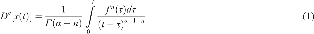
is the tire stiffness, k1 and c are the suspension stiffness and damping, respectively; b is the inertance of the P-FO inerter, which is passive as b is fixed, the fractional order of the P-FO inerter is μ (1<μ < 2); x1 and x2 are the vertical displacements of the sprung and unsprung masses, respectively; x0 is the road excitation displacement, when considering road harmonic excitation, it is expressed as X0cos (ωt), where X0 is the road excitation amplitude and ω is the excitation frequency. There are different ways to define the fractional calculus, here the Caputo’s definition
31
is adopted, which is expressed as Dynamic model of P-FOIB suspension.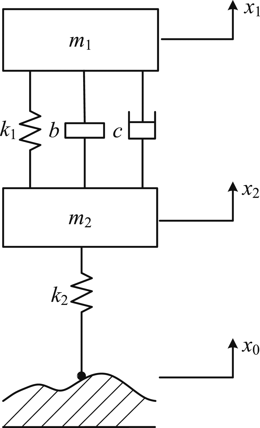
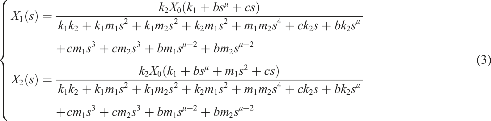
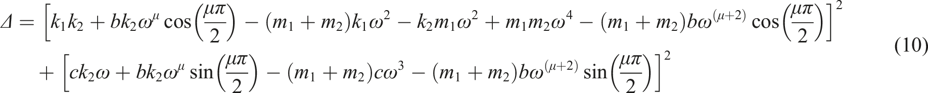
The dynamic equation of the P-FOIB suspension under road harmonic excitation is

The dynamic response of the P-FOIB suspension is obtained using the Laplace transform method, which is given as


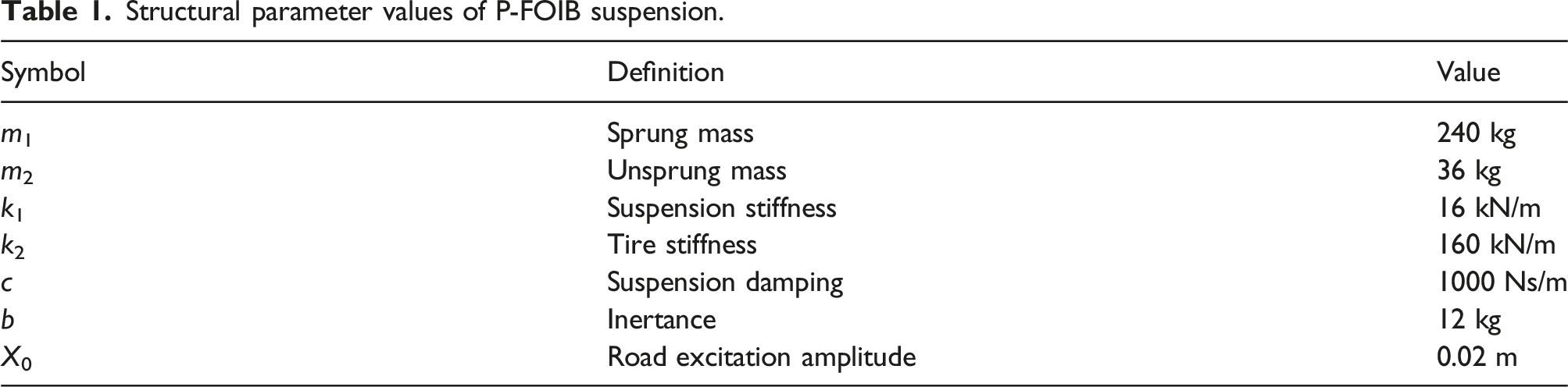
Structural parameter values of P-FOIB suspension.
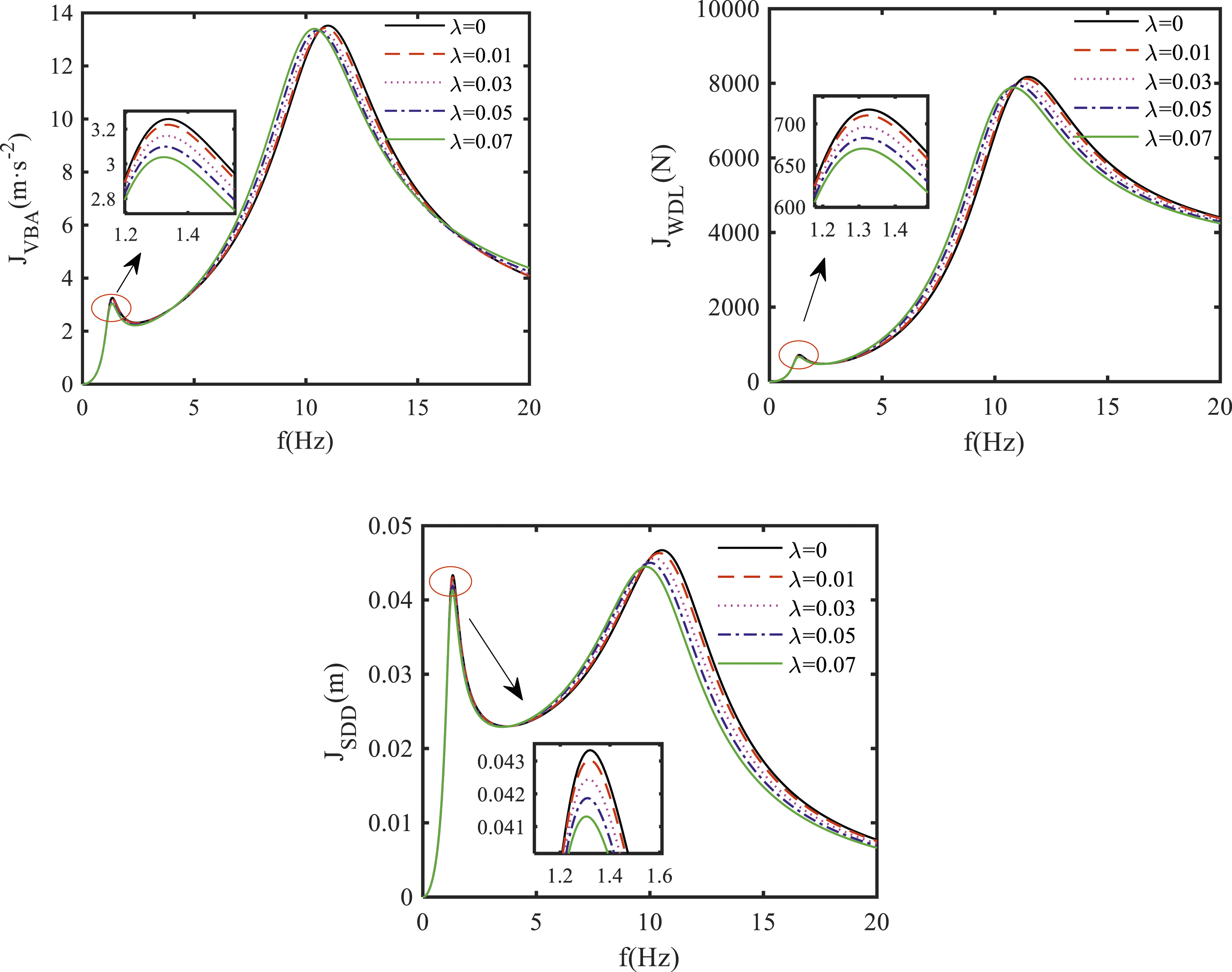
Dynamic performance indices of the P-FOIB suspension with different inertance-to-mass ratios under road harmonic excitation (μ = 1.7).
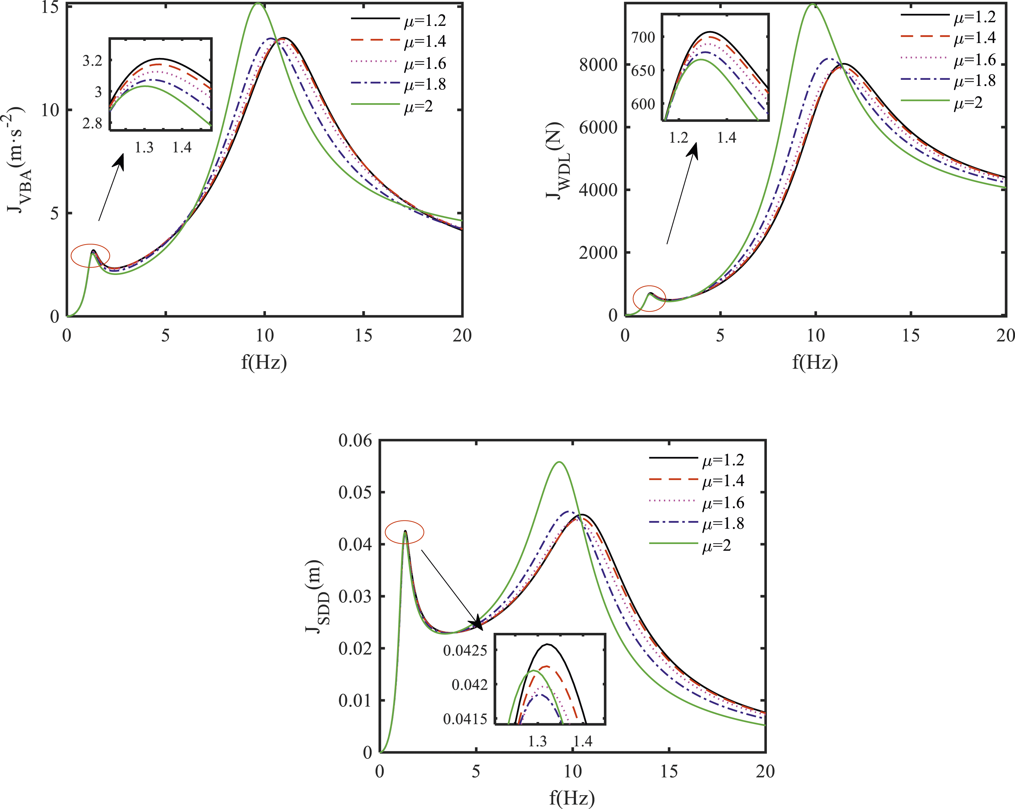
Dynamic performance indices of the P-FOIB suspension with different fractional orders under road harmonic excitation (λ = 0.05).
As shown in Figure 2, with the increase of the inertance-to-mass ratio, the low-frequency resonance peak of the vehicle body acceleration, the low-frequency and high-frequency resonance peaks of the suspension dynamic deflection and wheel dynamic load gradually decrease, while the high-frequency resonance peak of the vehicle body acceleration shows a trend of first decreasing and then increasing, and meanwhile, they are slightly lower than the traditional passive two-element suspension. As shown in Figure 3, with the increase of the fractional order, the high-frequency resonance peaks of the dynamic performance indices first decrease and then increase, while the corresponding low-frequency resonance peaks gradually decrease. Compared with the passive integer-order inerter-based (P-IOIB) suspension, the P-FOIB suspension has smaller high-frequency resonance peak and slightly larger low-frequency resonance peak. Thus, the SA-FO inerter is designed and the dynamic characteristic of the SA-FOIB suspension is investigated in the following part to see whether it can further improve the vehicle dynamics of the P-FOIB suspension.
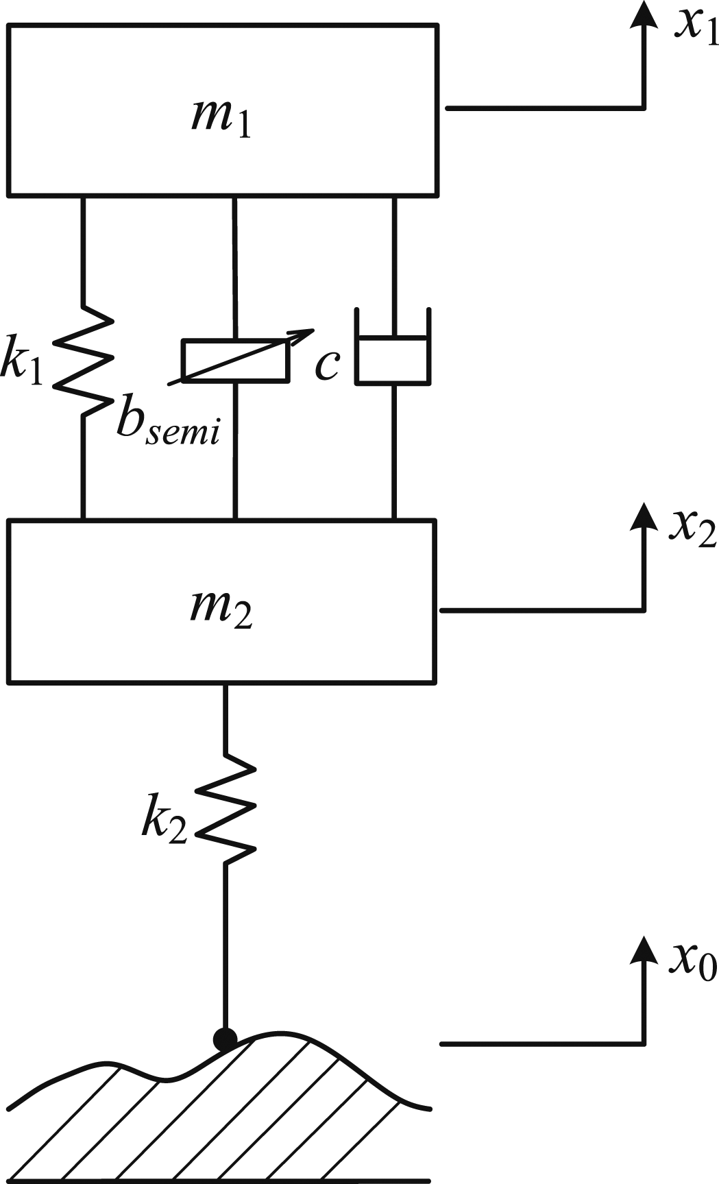
The prototype of a SA-FO inerter is shown in Figure 4, which is based on a hydraulic inerter. It mainly consists of a piston rod, piston, hydraulic cylinder, block buffer, high pressure electromagnetic valve, helical slender hard-tube and high pressure hose. Due to different diameters of two helical slender hard-tudes, the SA-FO inerter can have different inertances by adjusting the high pressure electromagnetic valve in an on or off state. The SA-FOIB suspension is shown in Figure 5, which is composed of a SA-FO inerter, a passive spring and a passive damper. The inertance of the SA-FO inerter is denoted as b
semi
and can be regulated, which has a regulated maximum inertance bmax and a regulated minimum inertance bmin. Prototype of a SA-FO inerter. Dynamic model of SA-FOIB suspension.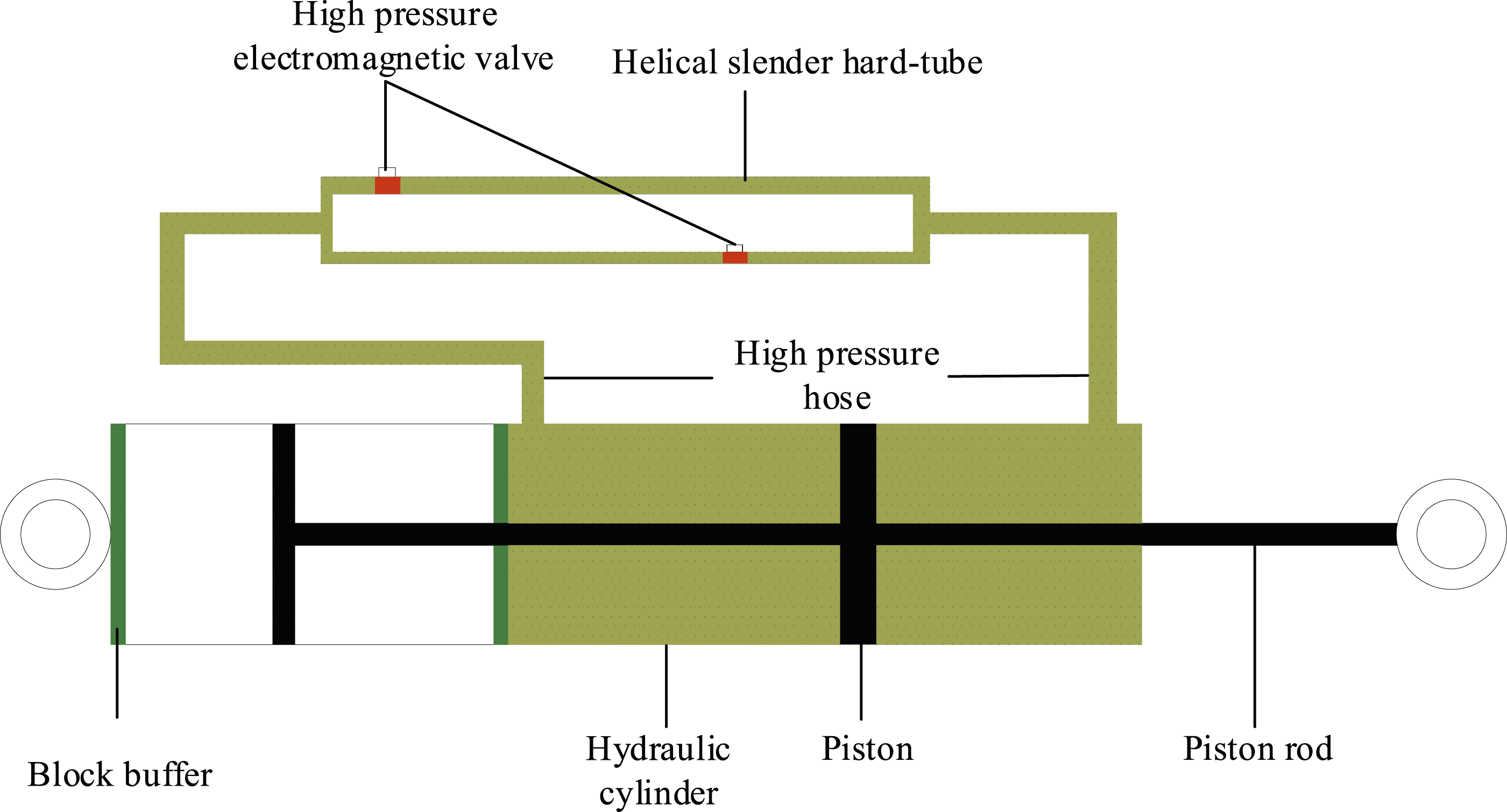
The dynamic equation of the SA-FOIB suspension under road harmonic excitation is


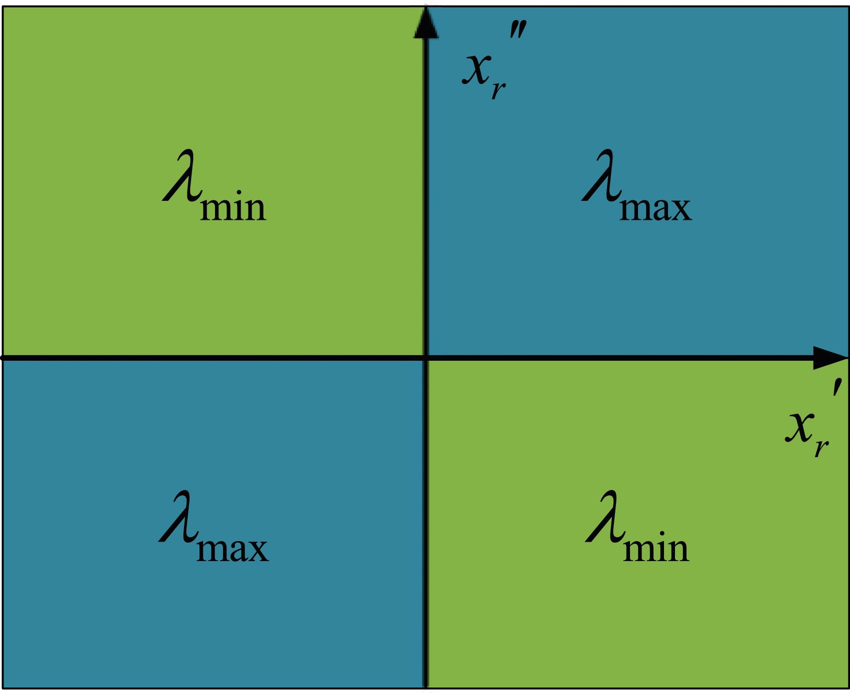
The AVS control strategy is used to adjust the inertance of the SA-FO inerter, which is based on the relative-acceleration-relative-velocity of the sprung and unsprung masses, the AVS control strategy is shown in Figure 6 and expressed as Schematic diagram of regulation law for AVS control strategy.
The SA-FOIB suspension is a two DOF piece-wise nonlinear dynamic system, its dynamic response under road harmonic excitation can be obtained conveniently by using the averaging method. The averaging method is also known as the constant variation method or slowly varying amplitude method, its physical essence is in each motion cycle, the motion of the nonlinear dynamic system is considered as a harmonic motion, the amplitude and phase in the second cycle only undergo slight changes compared to the first cycle, but remain unchanged for a sufficiently small period. Assuming the amplitude and phase of the dynamic response for the nonlinear dynamic system as slowly varying functions of the time, expanding the derivatives of the amplitude and phase as the Fourier series and taking their averaging values in one period, then the approximate solutions of the nonlinear dynamic system under harmonic excitation can be obtained. Thus, the approximate solutions of the sprung mass displacement x1 and relative displacement x
r
are assumed as


Differentiating equations (15) and (16) with respect to t, respectively, yields


Combining equations (16a) and (17a), equations (16b) and (17b) and yields

Substituting equations (15a), (15b), (17a), (17b), (18a), and (18b) into equation (13) yields


Combining equation (19a) with Eq. (20a), Eq. (19b) with equation (21a), the derivatives of the amplitudes a1 and a
r
, phases θ1 and θ
r
are obtained as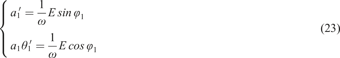
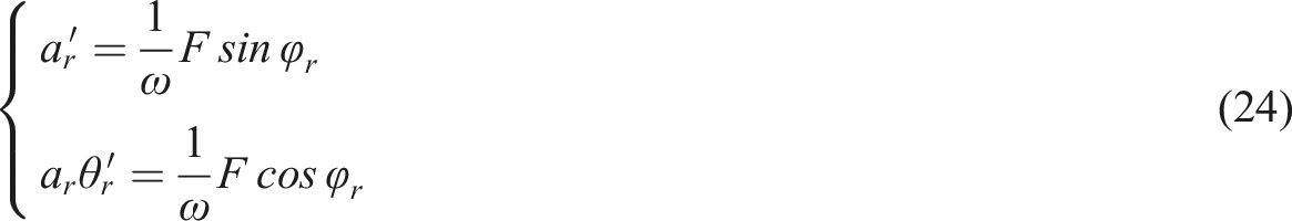
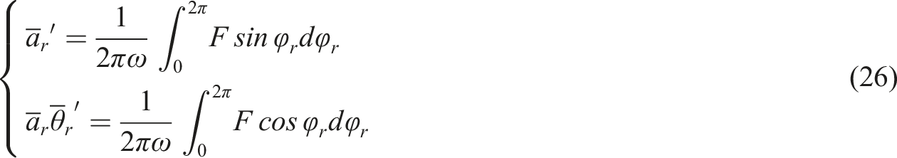
Based on the solution principle of the averaging method, the two items on the right side of equations (23) and (24) are integrated in one cycle and the averaging value is obtained, then the slow-varying amplitudes and phases in one cycle are given as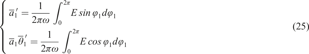
Substituting equation (15b) into equation (14), the semi-active control law is
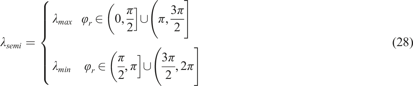
Combining equations (25), (26), and (28), setting 

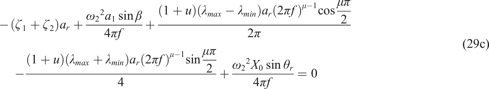
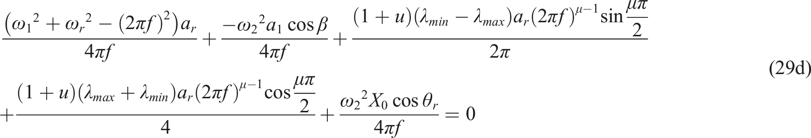
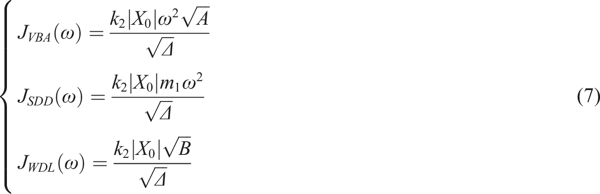
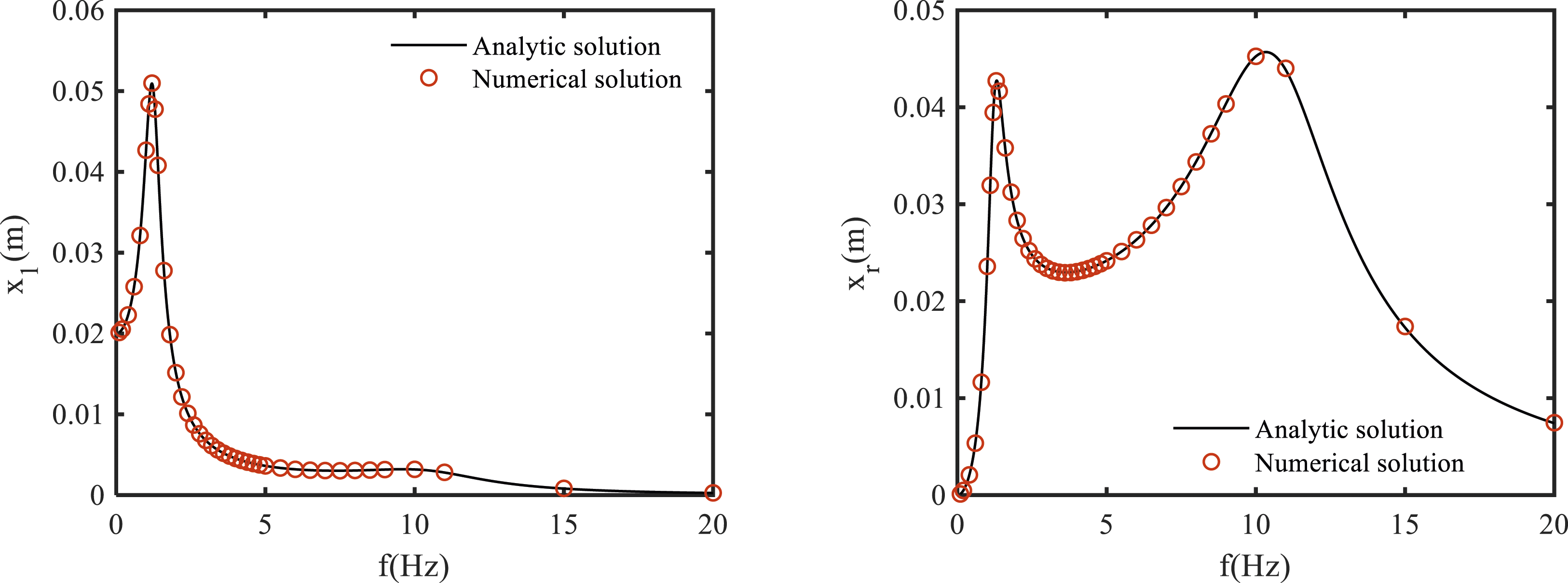
For a given excitation frequency f, the corresponding amplitude and phase can be obtained by solving the above four equations numerically. Then the three dynamic performance indices of the SA-FOIB suspension are Comparison of analytical and numerical solutions of the dynamic response for the SA-FOIB suspension (λmax = 0.02, λmin = 0.01).


Dynamic performance analysis of SA-FOIB suspension
Road harmonic excitation
Considering the road harmonic excitation firstly, which can show the dynamic performance of the SA-FOIB suspension in the frequency domain, the vehicle body acceleration J
VBA
, suspension dynamic deflection J
SDD
and wheel dynamic load J
WDL
are obtained using equations (30a), (30b), and (30c), respectively. The effect of the fractional order of the SA-FO inerter on the dynamic performance of the SA-FOIB suspension is shown in Figure 8, noting that when μ = 2, the SA-FOIB suspension is equivalent to the semi-active integer-order inerter-based (SA-IOIB) suspension. As the fractional order increases, the high-frequency resonance peaks of the dynamic performance indices first decrease and then increase, while the low-frequency resonance peaks show a decreasing trend. Compared with the SA-IOIB suspension, the SA-FOIB suspension obtains smaller high-frequency resonance peaks and slightly larger low-frequency resonance peaks, the changing trend is similar to the passive one. Dynamic performance indices of the SA-FOIB suspension with different fractional orders under road harmonic excitation (λmax = 0.2, λmin = 0.1).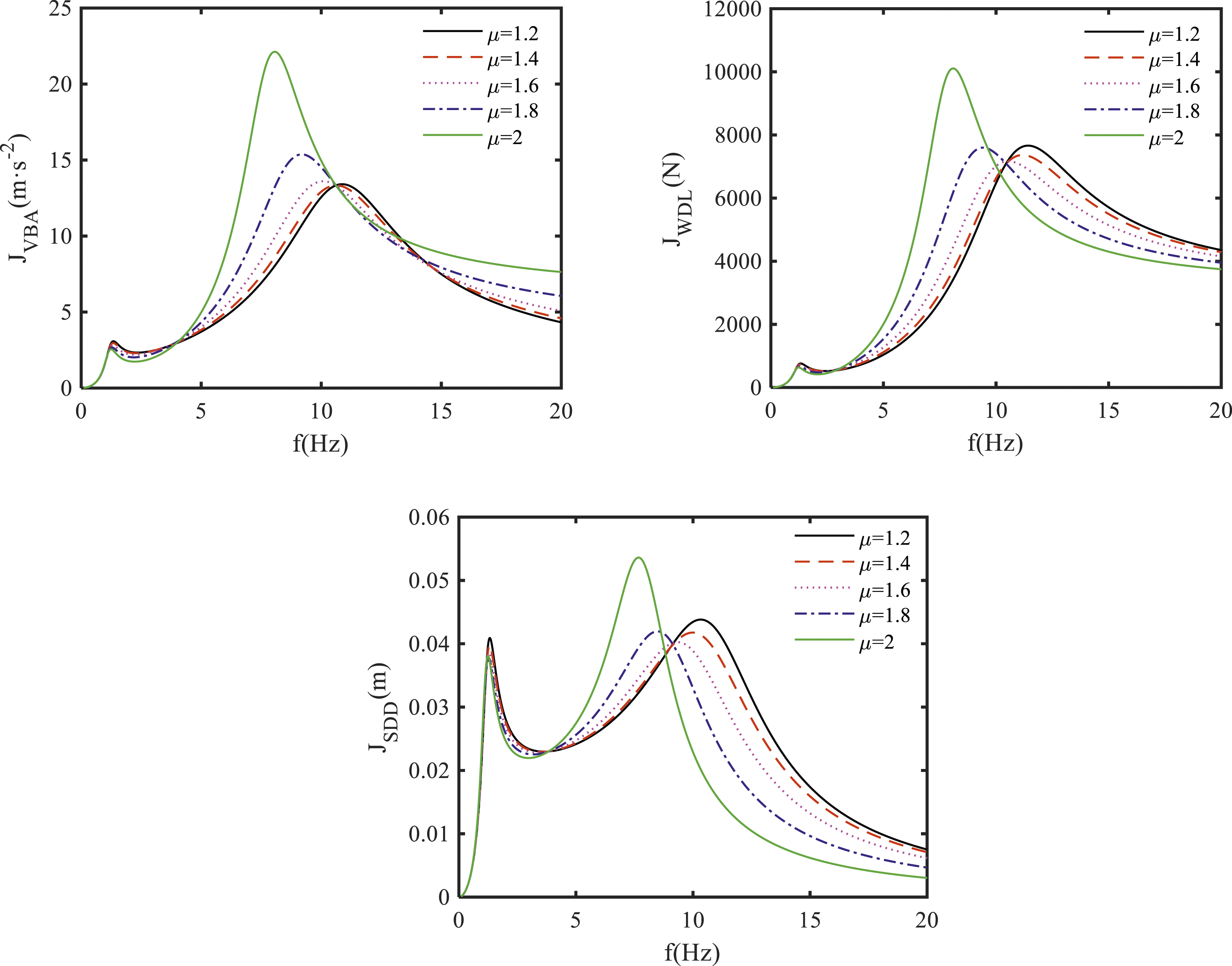
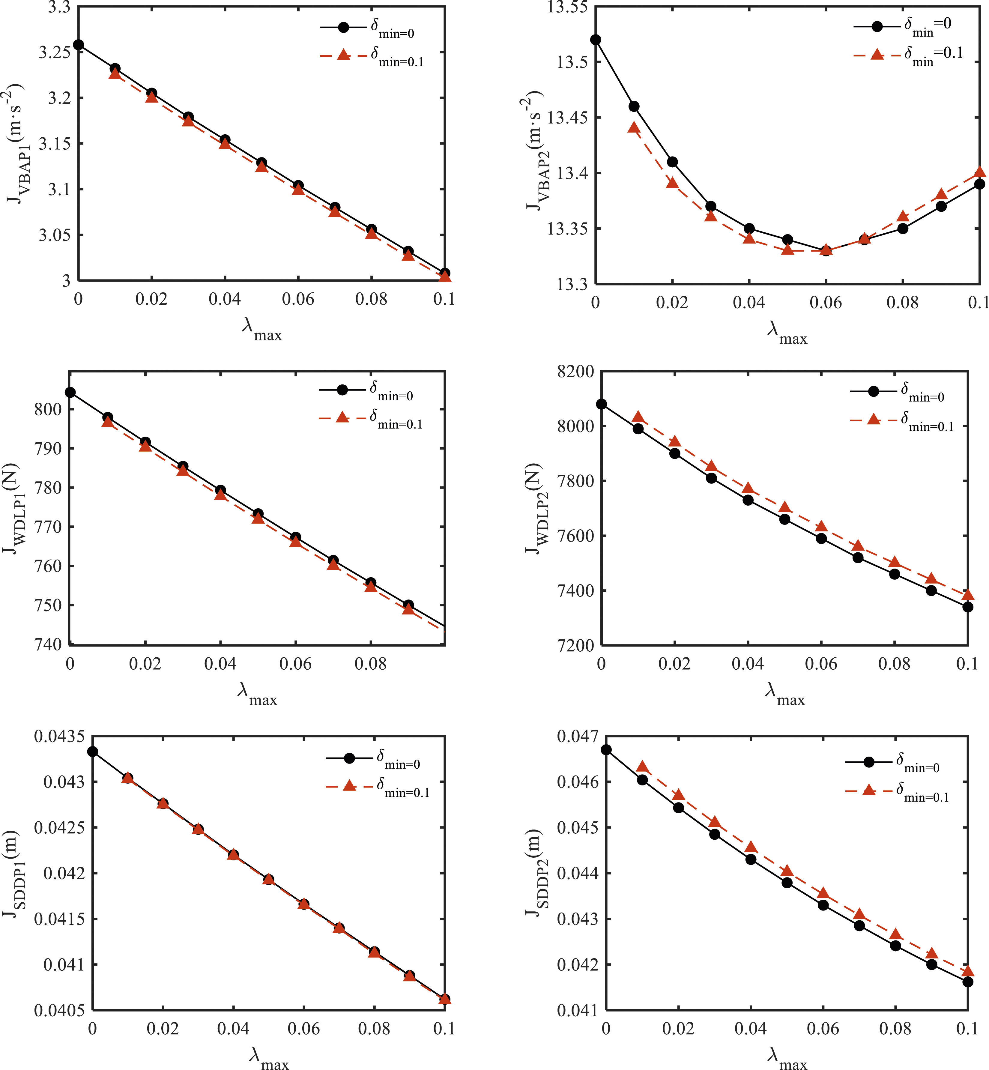
The dynamic performance indices of the SA-FOIB suspension with different λmax and λmin under road harmonic excitation are shown in Figures 9 and 10, respectively, the corresponding low-frequency and high-frequency resonance peaks are shown in Figures 11 and 12, respectively. As shown in Figures 9 and 11, when the minimum inertance-to-mass ratio λmin is fixed, with the increase of the maximum inertance-to-mass ratio λmax, the high-frequency resonance peak of the vehicle body acceleration first decreases and then increases, while the corresponding low-frequency resonance peak decreases, the low-frequency and high-frequency resonance peaks of the suspension dynamic deflection and wheel dynamic load shows a decreasing trend. Compared with the P-FOIB suspension, the low-frequency resonance peaks of the three dynamic performance indices are larger, while the high-frequency resonance peaks of the suspension dynamic deflection and wheel dynamic load are smaller, the high-frequency resonance peak of the vehicle body acceleration is first larger and then gradually smaller. Compared with the passive traditional two-element suspension (Curve 1: λ = 0 shown in Figure 9), the low-frequency and high-frequency resonance peaks of the three dynamic performance indices are smaller. Dynamic performance indices of the SA-FOIB suspension with different λmax under road harmonic excitation (λmin = 0, μ = 1.7, Curve 1: λ = 0, Curve 2: λ = 0.01, Curve 3: λ = 0.05, Curve 4: λ = 0.1, Curve 5: λmax = 0.01, Curve 6: λmax = 0.05, Curve 7: λmax = 0.1). Dynamic performance indices of the SA-FOIB suspension with different λmin under road harmonic excitation (λmax = 0, μ = 1.7, Curve 1: λ = 0, Curve 2: λ = 0.1, Curve 3: λmin = 0, Curve 4: λmin = 0.01, Curve 5: λmin = 0.05, Curve 6: λmin = 0.08). Low-frequency and high-frequency resonance peaks of the dynamic performance indices for the SA-FOIB suspension with different λmax under road harmonic excitation (μ = 1.7). Low-frequency and high-frequency resonance peaks of the dynamic performance indices for the SA-FOIB suspension with different λmin under road harmonic excitation (μ = 1.7).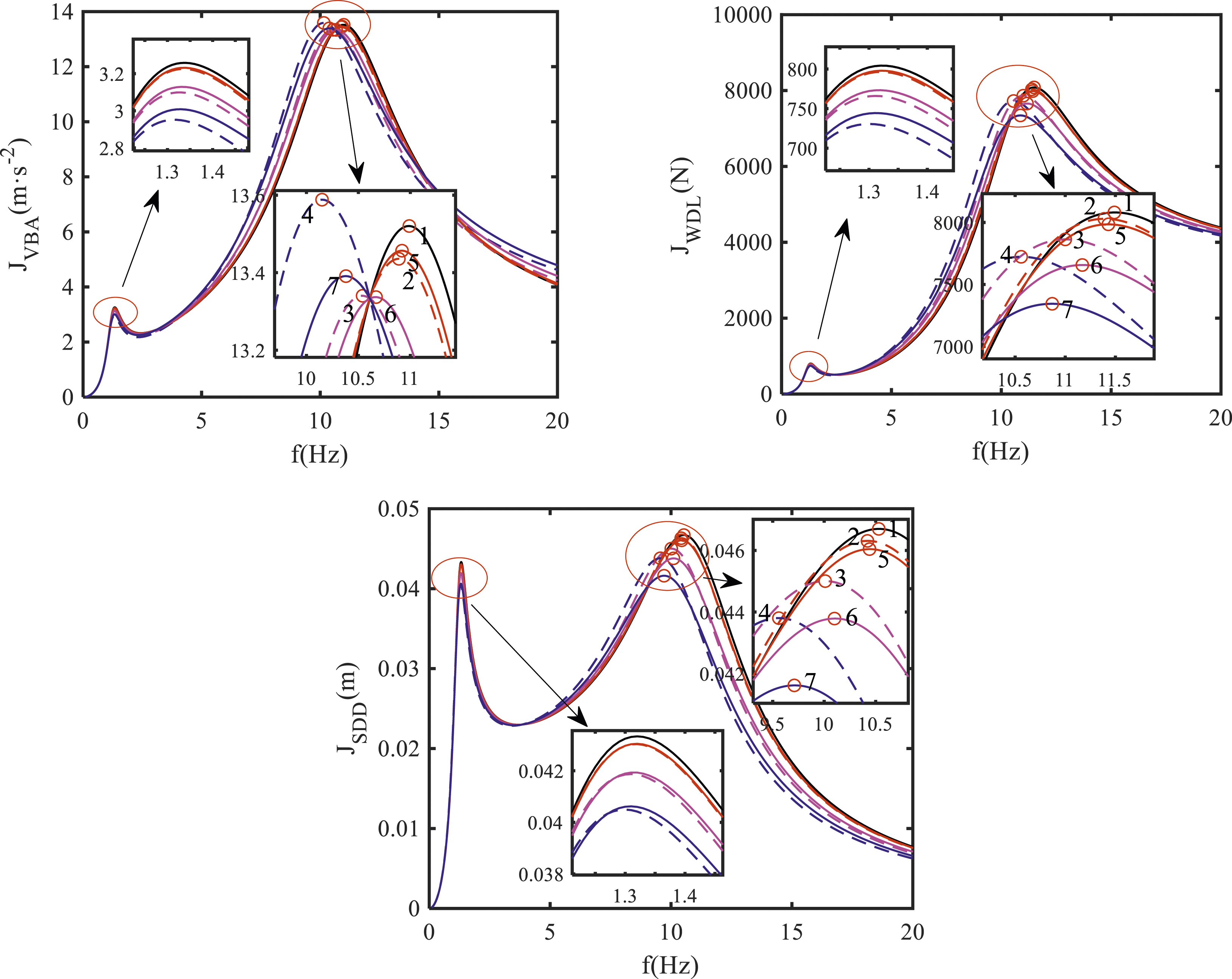
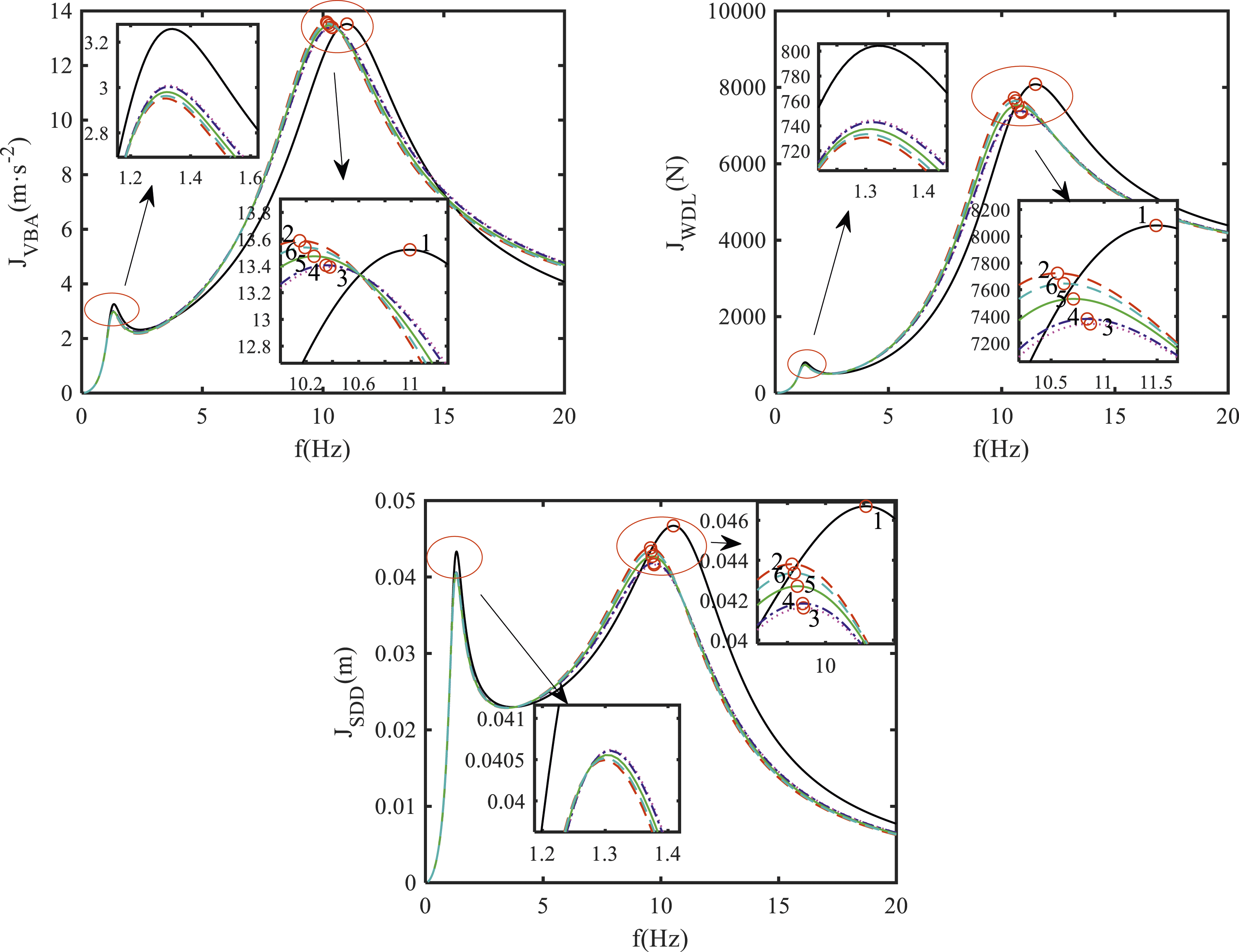
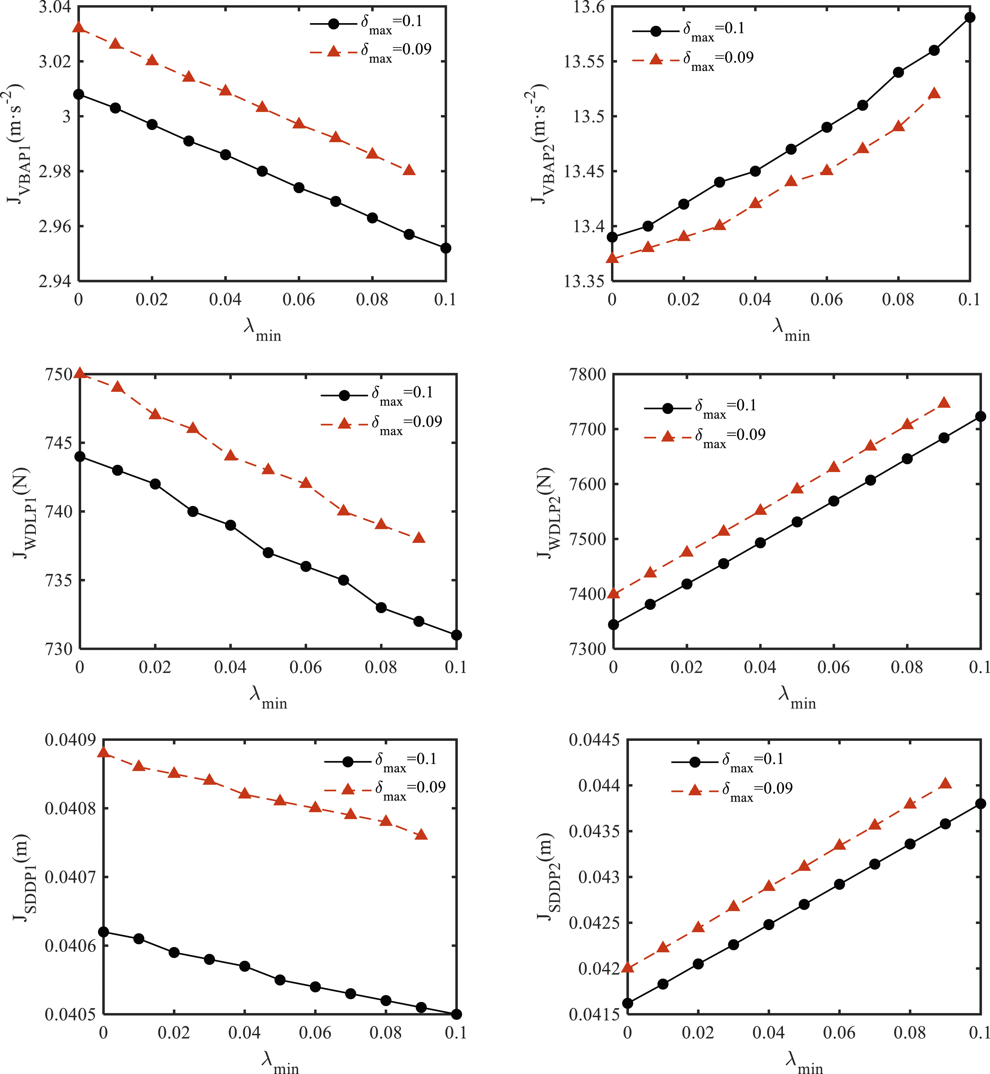
As shown in Figures 10 and 12, when the maximum inertance-to-mass ratio λmax is fixed, with the increase of the minimum inertance-to-mass ratio λmin, the low-frequency resonance peaks of the three dynamic performance indices all show a decreasing trend, while the corresponding high-frequency resonance peaks gradually increase. Compared with the P-FOIB suspension, the low-frequency resonance peaks of the three dynamic performance indices are larger, while the high-frequency resonance peaks are smaller. Compared with the passive traditional two-element suspension (Curve 1: λ = 0 shown in Figure 10), the low-frequency resonance peak of the vehicle body acceleration, the low-frequency and high-frequency resonance peaks of the suspension dynamic deflection and wheel dynamic load are smaller, while the high-frequency resonance peak of the vehicle body acceleration is gradually larger with the increase of the minimum inertance-to-mass ratio.
In summary, for road harmonic excitation, the SA-FOIB suspension can further improve the high-frequency dynamic performance of the P-FOIB suspension, where the high-frequency resonance peaks of the three dynamic performance indices are smaller, and can also obtain a better dynamic performance than the passive traditional two-element suspension, where both the low-frequency and high-frequency resonance peaks of the three dynamic performance indices are smaller.
Road random excitation
Then considering the road random excitation, the filtered white noise method is used to simulate the random excitation of the class C road profile, the dynamic performance of the SA-FOIB suspension under road random excitation is investigated, the root-mean-square (RMS) values of the dynamic performance indices are shown. The time domain model of the filtered white noise road roughness is
The effect of the fractional order of the SA-FO inerter on the dynamic performance of the SA-FOIB suspension under road random excitation is shown in Figure 13. As the fractional order increases, the three dynamic performance indices show a trend of first decreasing and then increasing, the RMS value of the vehicle body acceleration has a minimum value when the fractional order is around 1.2, the RMS values of the suspension dynamic deflection and wheel dynamic load have the minimum values when the fractional order is around 1.9. The RMS value of the dynamic performance indices for the SA-FOIB suspension with different μ under road random excitation (λmax = 0.1, λmin = 0).
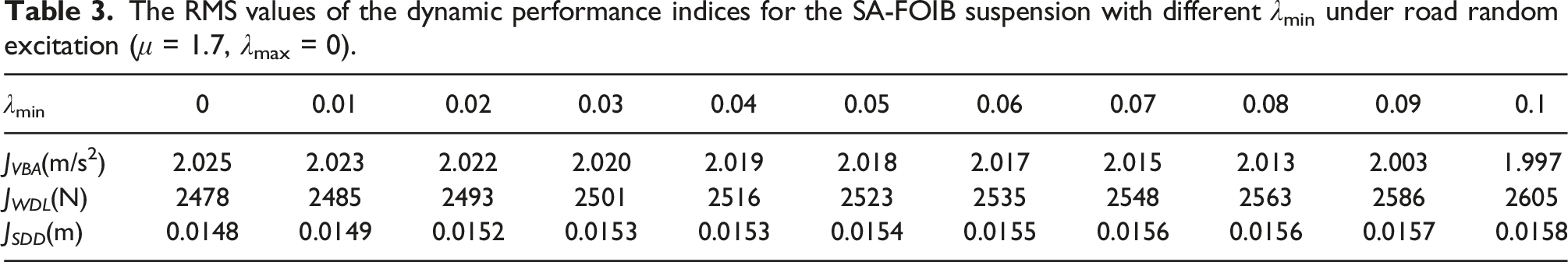
The dynamic performance indices of the SA-FOIB suspension with different λmax and λmin under road random excitation are shown in Figures 14 and 15, respectively, the corresponding detailed RMS values of the dynamic performance indices are shown in Tables 2 and 3, respectively. When the minimum inertance-to-mass ratio λmin is fixed, with the increase of the maximum inertance-to-mass ratio λmax, the RMS value of the vehicle body acceleration gradually increases, while the RMS values of the suspension dynamic deflection and wheel dynamic load gradually decrease. When the maximum inertance-to-mass ratio λmax is fixed, with the increase of the minimum inertance-to-mass ratio λmin, the RMS value of the vehicle body acceleration gradually decreases, while the RMS values of the suspension dynamic deflection and wheel dynamic load gradually increase. Compared with the P-FOIB suspension, the RMS value of the vehicle body acceleration is larger, while the RMS values of the suspension dynamic deflection and wheel dynamic load are smaller. Dynamic performance indices of the SA-FOIB suspension with different λmax under road random excitation (μ = 1.7, λmin = 0). Dynamic performance indices of the SA-FOIB suspension with different λmin under road random excitation (μ = 1.7, λmax = 0). The RMS values of the dynamic performance indices for the SA-FOIB suspension with different λmax under road random excitation (μ = 1.7, λmin = 0). The RMS values of the dynamic performance indices for the SA-FOIB suspension with different λmin under road random excitation (μ = 1.7, λmax = 0).
Structural parameters optimization of SA-FOIB suspension
In this Section, the structural parameters optimization of the SA-FOIB suspension subjects to the road random excitation is investigated, which is based on the genetic algorithm, three mainly structural parameters are optimized, the damping of the SA-FOIB suspension (c), the maximum and minimum inertance-to-mass ratios of the SA-FOIB suspension (λmax, λmin) and the fractional order of the SA-FO inerter (μ). The basic idea of the genetic algorithm is to simulate the natural selection mechanism of the biological evolution. Through selection, crossover, mutation and other means, it can continuously generate individuals with stronger adaptability to the environment. It is a strong robust algorithm that can solve optimization problems. The goal of structural parameters optimization of the SA-FOIB suspension is to reduce the vehicle body acceleration and wheel dynamic load, and the objective function of the dynamic performance optimization for the SA-FOIB suspension can be expressed as
The calculation process of the structural parameters optimization for the SA-FOIB suspension is as follows: (a) Genetic algorithm initialization. Population size, chromosome length, crossover and mutation probability and stopping rules are set through the MATLAB Genetic Algorithm Toolbox. (b) Sorting the mutated population by fitness continuously, and selecting individuals with high fitness as new populations. When the results meet the termination conditions, the optimal structural parameters of the SA-FOIB suspension (c, λmax, λmin, μ) are calculated.
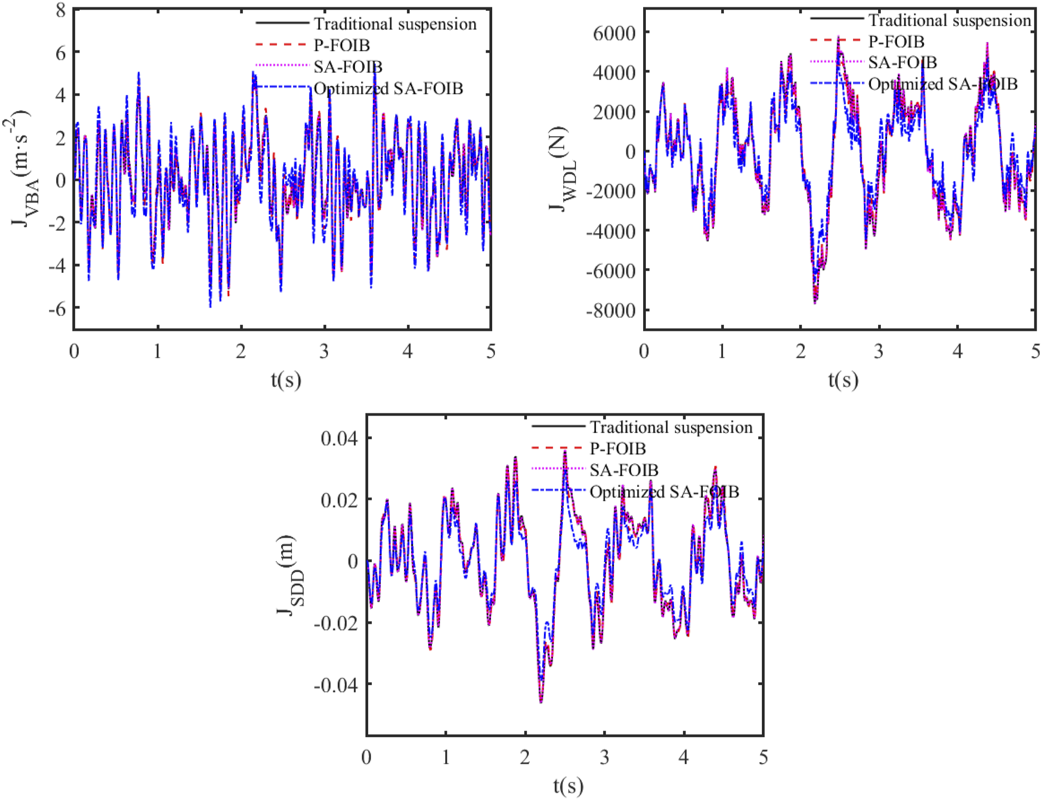
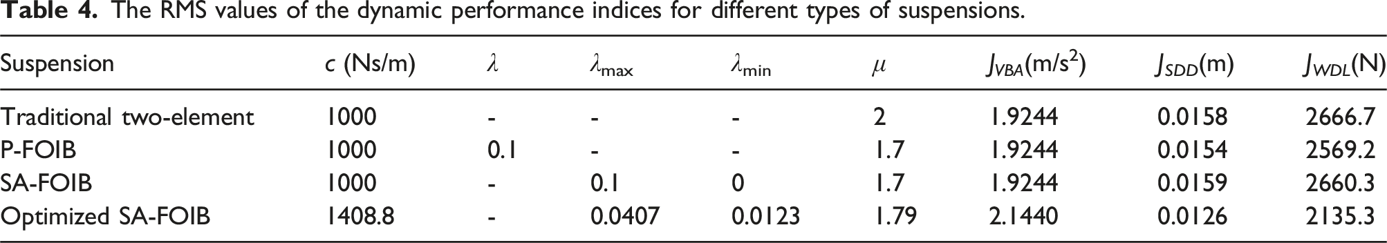
The convergent process of the genetic algorithm is shown in Figure 16, when the genetic algorithm iteration reaches at 18 iteration and the average change of fitness values is very small, the optimal structural parameters of the SA-FOIB suspension are obtained as: c = 1408.8 Ns/m, λmax = 0.0407, λmin = 0.0123, μ = 1.79. The dynamic performance of the optimized SA-FOIB suspension is compared with three other suspensions: the traditional two-element suspension (λ = 0), the P-FOIB suspension (λ = 0.1, μ = 1.7) and the unoptimized SA-FOIB suspension (λmax = 0.1, λmin = 0, μ = 1.7). The dynamic performance indices for four types of suspensions are compared in Figure 17, the corresponding RMS values are shown in Table 4. For the traditional two-element suspension, the RMS values of the three dynamic performance indices are 1.9244 m/s2, 0.0158 m and 2666.7 N, respectively. The corresponding RMS values for the P-FOIB suspension is 1.9840 m/s2, 0.0154 m and 2569.2 N, respectively, which improves the suspension dynamic deflection and wheel dynamic load by 2.53 % and 3.66 %, respectively, while worsens the vehicle body acceleration by 3.09 % compared with the traditional two-element suspension. For the unoptimized SA-FOIB suspension, the RMS values of the three dynamic performance indices are 1.9517 m/s2, 0.0159 m and 2660.3 N, respectively, compared with the P-FOIB suspension, the RMS value of the vehicle body acceleration decreases by 1.63 %, while the RMS values of suspension dynamic deflection and wheel dynamic load increase by 3.25 % and 3.55 %, respectively. When using the genetic algorithm optimization, for the optimized SA-FOIB suspension, the RMS values of the three dynamic performance indices are 2.1140 m/s2, 0.0126 m and 2135.3 N, respectively, which improves the suspension dynamic deflection and wheel dynamic load by 20.75 % and 19.73 %, respectively, while worsens the vehicle body acceleration by 8.32 % compared with the unoptimized SA-FOIB suspension, it obtains the smallest suspension dynamic deflection and wheel dynamic load among the four suspensions. The convergent process of the genetic algorithm. Comparison of the time domain response of the dynamic performance indices for different types of suspensions. The RMS values of the dynamic performance indices for different types of suspensions.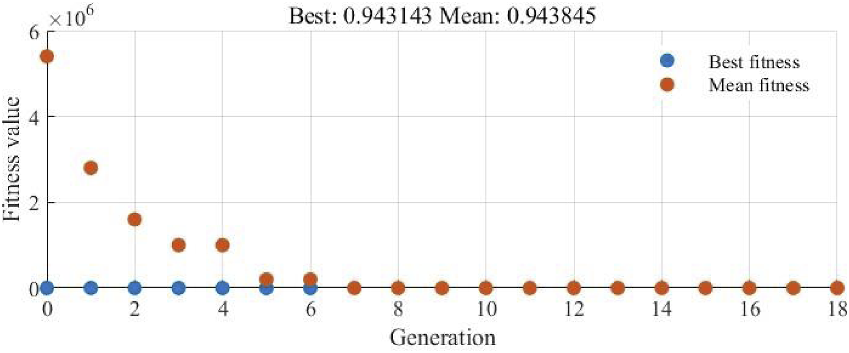
In order to show the effectiveness of the optimized SA-FOIB suspension more clearly, the comparison of the power spectral density of the dynamic performance indices for different types of suspensions is shown in Figure 18, which is expressed in the logarithm coordinate. It can be further seen that compared with the other three suspensions, the optimized SA-FOIB suspension decreases the vehicle body acceleration, suspension dynamic deflection and wheel dynamic load in the high-frequency band, while increases them in the low-frequency band which is below 1 Hz. Comparison of the power spectral density of the dynamic performance indices for different types of suspensions.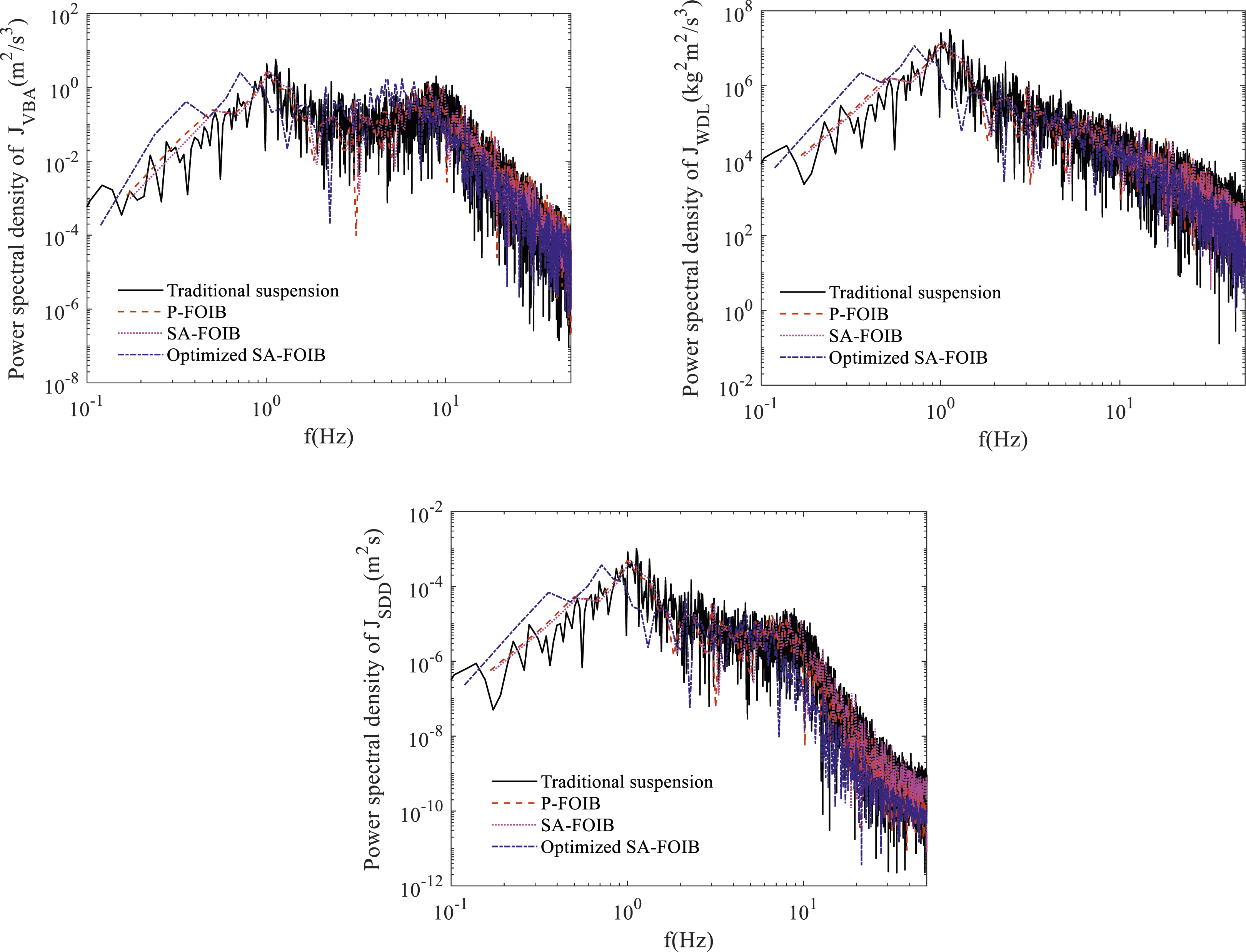
Conclusion
In this paper, the SA-FO inerter is proposed and used in the vehicle suspension to constitute the SA-FOIB suspension, which consists of two adjustable inertances. Based on the mechanical characteristic of the inerter, the AVS control strategy is proposed to adjust the inertance of the SA-FO inerter. The dynamic model of the SA-FOIB suspension with AVS control is established, its dynamic response under road harmonic excitation is obtained using the averaging method, the dynamic performance under road harmonic and random excitations is analyzed, the optimized structural parameters are obtained. The conclusions are summarized as follows: (1) The P-FOIB suspension has smaller high-frequency resonance peaks and slightly larger low-frequency resonance peaks for the dynamic performance indices than the P-IOIB suspension. The SA-FOIB suspension is a two DOF piece-wise nonlinear dynamic system, its dynamic response under road harmonic excitation is obtained using the averaging method, the analytical solution is consistent with the numerical solution, which verifies the effectiveness of the averaging method for solving fractional-order piece-wise nonlinear dynamic system. (2) When the SA-FOIB suspension is under road harmonic excitation, it can further enhance the high-frequency dynamic performance of the P-FOIB suspension, which the high-frequency resonance peaks of the three dynamic performance indices are smaller. For road random excitation, its RMS value of the vehicle body acceleration is larger, while the RMS values of the suspension dynamic deflection and wheel dynamic load are smaller, compared with the P-FOIB suspension. (3) The optimized structural parameters of the SA-FOIB suspension is obtained using the genetic algorithm optimization method, the optimized SA-FOIB suspension has smaller suspension dynamic deflection and wheel dynamic load than the traditional two-element, P-FOIB and unoptimized SA-FOIB suspensions, which are smallest among the four suspensions, while the vehicle body acceleration is larger.
Footnotes
Declaration of conflicting interests
The author(s) declared no potential conflicts of interest with respect to the research, authorship, and/or publication of this article.
Funding
The author(s) disclosed receipt of the following financial support for the research, authorship, and/or publication of this article: This work was supported by the National Natural Science Foundation of China (Grant No. 12172153, 51805216), Natural Science Foundation of Jiangsu Province (Grant No. BK20231360), National Key Laboratory of Automotive Chassis Integration and Bionics (Jilin University) (Grant No. 20210212), Major Project of Basic Science (Natural Science) of the Jiangsu Higher Education Institutions (22KJA410001), Changzhou Science and Technology Program (CZ20240019) and the project funded by the Youth Talent Cultivation Program of Jiangsu University.