
Abstract
The integration of a motor-gear system (MGS) can introduce complex electromechanical coupling dynamics issues. For example, mechanical vibrations within the gear transmission system (GTS) may cause deviations in the actual output power of motor, while torque fluctuations of motor can lead to significant impacts and vibrations during gear meshing. Consequently, this paper primarily addresses abnormal vibrations resulting from electromechanical coupling in MGS and investigates methods for their suppression. The objective is to examine the effect of various motor control techniques on the dynamics of MGS. Initially, a universal modeling approach for MGS, adaptable to different engineering scenarios with simple modifications to gear or motor parameters, is developed. This model includes the equivalent circuit model of the permanent magnet synchronous motor (PMSM), mathematical model of the motor rotor, and bending-torsion coupling model of the GTS. Coupling channels are established between these local models, facilitating the construction of a comprehensive electromechanical coupling dynamic model of MGS. The efficacy of this proposed model is validated through experimentation. Subsequently, different motor control techniques based on this model to assess their effects on the dynamics of both motor and GTS are analyzed. The results suggest that, without altering the mechanical structure of system, the dynamic behaviors of MGS can be improved through the implementation of motor control strategies. This approach aids in mitigating the exacerbation of abnormal vibrations within the MGS.
Introduction
The motor-gear system (MGS) is a commonly used drive system in mechanical equipment, characterized by advantages such as high efficiency, torque, and precision. To enhance the integration of drive systems, the MGS is evolving towards structural and control integration. 1 However, integrated MGS also face new problems and challenges, among which electromechanical coupling dynamics and their control issues are topics urgently needing in-depth research. 2
The MGS represents a classic example of an electromechanical coupling system. To investigate the electromechanical coupling characteristics of motor rotor, 3 initially developed an electromechanical dynamic model based on the Jeffcott rotor, adding two additional variables of rotor harmonic currents. 4 analyzed the electromechanical coupling dynamic of wound rotor induction generators through simulation and experimentation, demonstrating that frequency components related to the sun gear rotation frequency can be detected in the stator current spectrum. 5 utilized the modal energy method to determine the resonance frequency of the generator under variable speed and load conditions. For the nonlinear dynamic characteristics of vehicle compound motor transmission systems, 6 proposed an electromechanical coupling model of permanent magnet synchronous motor (PMSM) rotor, studying the dynamic transmission relationship between the mechanical system and electric drive system (EDS). Regarding the electromechanical coupling dynamic problems of high-speed induction generators supported by magnetic bearings, 7 studied the influence of unbalanced magnetic forces on the torsional vibration of system. On the other hand, 8 explored the electromechanical coupling dynamic characteristics between the EDS and gear transmission system (GTS) of electric vehicle under current harmonic excitation. Despite these advancements, research into the electromechanical coupling dynamics of MGS remains in its infancy, often overlooking the influence of coupling relationships on dynamic behaviors.
Dynamic modeling is a fundamental issue that continues to be the subject of extensive research among scholars. To effectively study the electromechanical coupling dynamics of MGS, it is essential to establish a precise dynamic model. However, current modeling approaches for MGS predominantly focus on local modeling, often overlooking the critical coupling relationships between electrical and mechanical systems. For instance, the 4 degree of freedom (DOF) model 9 was utilized to analyze the torsional dynamics of GTS involving input and output torque. Furthermore, for investigating the impact of gear lateral vibration on dynamic behaviors of GTS, the 8 DOF model 10 was adopted for the bending-torsional coupling dynamic analysis of GTS. In cases where the gear is asymmetrically installed with a long span, the 12 DOF model 11 considering gear axial swinging was also presented. Additionally, the 24 DOF model 12 comprehensively considers the influence of gear support by bearings at both ends was introduced. 13 took a different approach, simulating the nonlinear dynamic characteristics of GTS using an intermittent gear mesh model that incorporates flexible teeth. As early as 1991, a dynamic model of electromechanical coupling between motors and mechanisms was proposed by Liou et al. (1991) 14 ; conducting simple analysis thereafter. Subsequent research has explored the impact of gear faults on motor current responses and has extracted gear fault features from the dynamics of these current responses. 15 In addressing the electromechanical coupling dynamic problems of coal mining machinery and wind power equipment, scholars have established the electromechanical coupling dynamic model of MGS5,16,17 further investigated the electromechanical coupling torsional resonance characteristics of multi-stage gear transmission systems (GTS) driven by low-speed high-power PMSM, taking into account the electromagnetic effects and bending-torsional vibrations of coal mining machinery. 18 Chen et al. (2022) constructed a dynamic model of electric motors to obtain motor torque and analyzed the electromechanical dynamic characteristics of planetary gears in electric vehicles during constant speed and variable speed processes. 19 Sang et al. (2021) analyzed the feasibility of using the lateral synthesized vibration signal and output torsional vibration signal of the motor-3K planetary gear system for fault diagnosis. 20 Guo et al. (2022) summarized the cross-coupling problems of coupled systems based on vehicle transmission systems, establishing a coupling dynamic model involving electrical, magnetic, and mechanical elements. While existing studies have investigated certain electromechanical coupling problems of MGS and primarily focused on the torsional dynamic modeling of system, the multidimensional electromechanical coupling between EDS and GTS remains underexplored.
Dynamic research on EDS encompasses several key areas, including dynamic modeling, motor control, motor optimization design, and intelligent motor diagnostics. The application of dynamic control technology to motors can significantly enhance system performance, accuracy, and stability, thereby meeting the requirements of various application scenarios. To achieve high-performance control for motors, 21 Sripang et al.(2022) proposed a nonlinear control strategy with parameter identification and conducted experimental verification. 22 Liu et al. (2019) utilized MATLAB to simulate and analyze the dynamic response and control of a ring motor. 23 Shang et al. (2020) introduced a fixed-time robust control method for trajectory tracking control of systems with motor dynamics, addressing unmodeled and external disturbances. 24 Shojaei et al. (2020) presented a neural adaptive control scheme based on performance metrics, designed to manage motor dynamics in the presence of model uncertainty, especially relevant for robot manipulators where velocity, acceleration, and input current measurements may be limited. Despite these advancements, current research on the dynamic control of motors is still undergoing in-depth exploration, aiming to develop solutions that offer high precision, multifunctionality, and intelligence to meet diverse control needs while considering specific application requirements. However, the analysis of the effects of motor control strategies on the dynamic response of both motors and gear trains remains an area that requires further investigation.
Research on the dynamics of motor-gear systems (MGS) has evolved significantly, incorporating advancements in modeling techniques, simulation tools, experimental validation, and application-specific studies. Despite notable achievements in the electromechanical coupled dynamic research of MGS, several challenges persist, such as inadequate model accuracy, insufficient consideration of electromechanical coupling factors, low modeling efficiency, and the complexity of motor control strategies. Consequently, this paper emphasizes a holistic approach to understanding and optimizing the dynamic behavior of MGS, integrating advanced modeling techniques, experimental validation, motor control, and application-specific considerations. We also investigate the impact of motor control strategies on the dynamic response of both motor and gear. The structure of the paper is as follows: Section 2 initially formulates the electromechanical coupling dynamic model of MGS, which integrates the EDS and GTS, and includes a concise description and algorithm of motor control methods. Section 3 presents the effectiveness validation of the dynamic model for MGS. Section 4 compares various motor control methods to evaluate their effects on the dynamic response of EDS and GTS. This comprehensive analysis aims to deepen the understanding of the interplay between motor control technologies and the broader dynamics of MGS. Finally, conclusions are drawn in the concluding section.
Dynamic modeling
Exploring the electromechanical coupling dynamics of the motor-gear system (MGS) requires the establishment of a high-precision dynamic model for the system. Figure 1 illustrates the structural diagram of the MGS, while the development of this intricate model spans multiple interdisciplinary domains, including mechanics, electromechanics, and control. Additionally, it is essential to consider the modeling of both the EDS and GTS, along with excitation parameters and nonlinear factors. However, for the sake of simplicity, the coupling relationships of the MGS are often simplified in the modeling process.25–27 This chapter establishes the dynamic models of the PMSM and GTS, grounded in the modeling and analysis of multiple coupling systems. By examining the coupling relationships between the PMSM and GTS, the chapter derives the electromechanical coupling dynamics of the MGS. This foundational model is pivotal for analyzing the electromechanical coupling dynamic characteristics discussed in this paper. Diagram of the electromechanical coupling system comprising the motor and gear.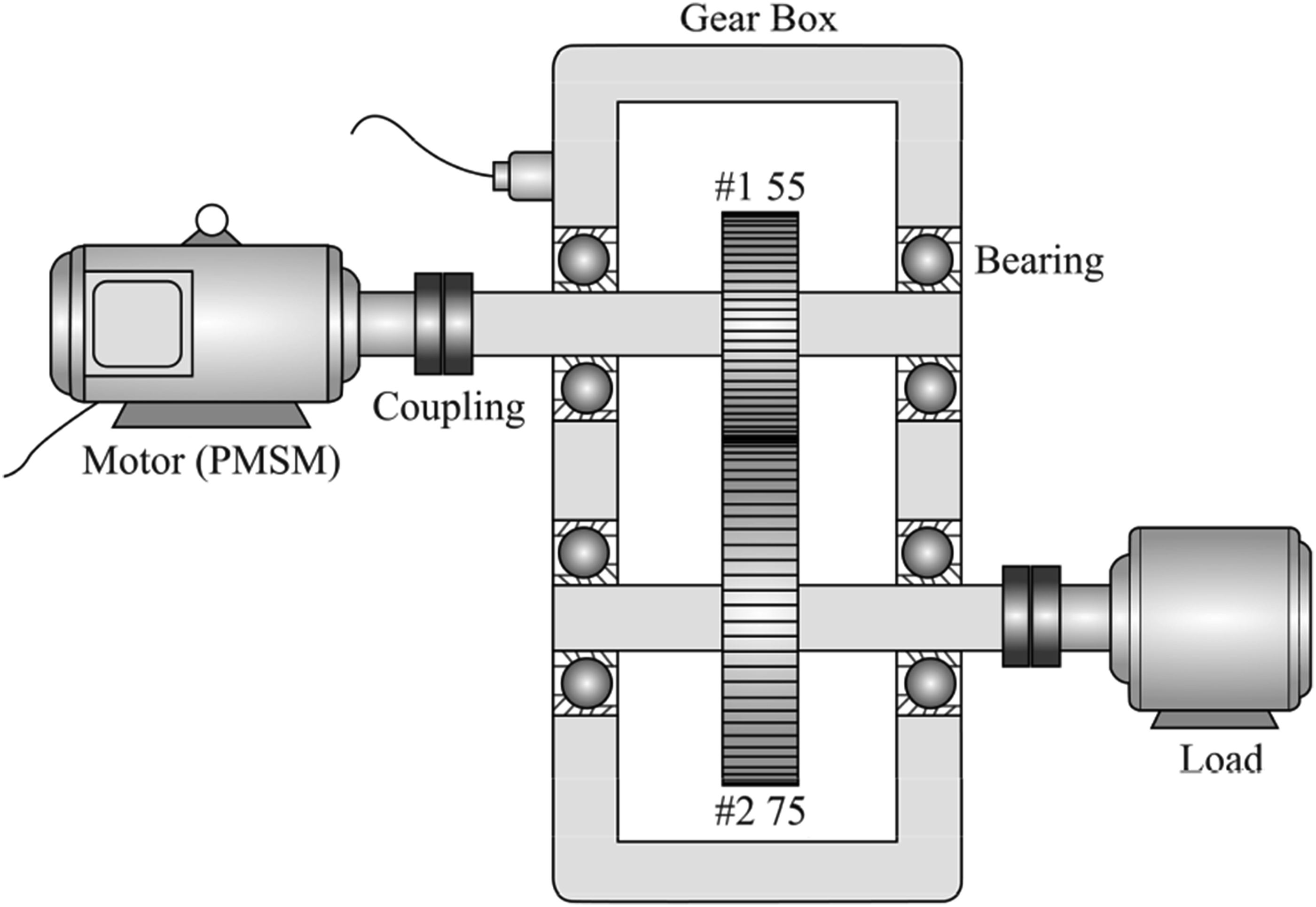
Mathematical model of PMSM
Establishing the mathematical model of the EDS forms the foundation for studying the electromechanical coupling dynamics of the entire system. The relative motion between the stator and rotor of the PMSM causes harmonics in the magnetic field density of the air gap, resulting in a complex electromagnetic relationship. Considering the disturbance of current harmonics and parameters such as electrical conductivity and magnetic permeability further increases the modeling complexity. Therefore, the following assumptions are made for the modeling of the PMSM: (1) The three-phase windings of the PMSM are assumed to be symmetric, with a spatial phase difference of 2π/3 in electrical angle, and the magnetic field distribution along the air gap is assumed to be sinusoidal; (2) Factors such as motor inverters, current harmonics, and slot effects are disregarded, and hysteresis and eddy current losses are not accounted for; (3) The influence of temperature variations and changes in power supply frequency on parameters is neglected.
Based on the above assumptions, the stator voltage equation of a three-phase PMSM in the natural coordinate system can be expressed as
22


Equations (1) to (3) constitute the basic mathematical model of a three-phase PMSM in the a-b-c frame. The flux linkage equation reveals that the flux linkage of the stator is a function of the rotor position angle (θ
e
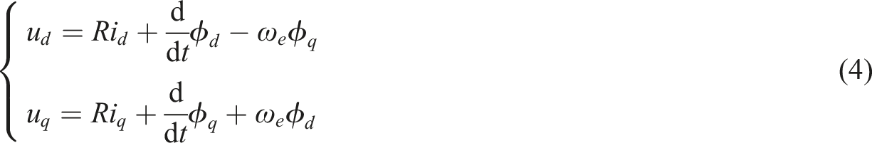
). The voltage equation of the stator in the rotating q-d reference frame, after applying the Clark and Park transformations, is typically expressed in a simplified form to facilitate analysis and control of PMSM. The transformations allow the complex three-phase system to be represented in a two-phase system that rotates with the rotor, making it easier to analyze and control. The voltage equations in the q-d frame are given by
The flux linkage equation in the rotating q-d frame is

The torque equation can be formulated as

The Park model of PMSM is established by equations (4) to (6). Besides, it is important to consider the following relationships

A simplified rotor dynamic model as a single degree of freedom torsional system is used to simulate motion with torsional stiffness and damping. However, lateral vibrations can affect the stator-rotor air gap, causing motor vibration and noise. To better understand these effects, especially in GTS where meshing impacts can also alter the air gap, a coupled lateral-torsional model of the rotor is developed to improve the electromechanical coupling dynamic model of PMSM.
As shown in Figure 2, a similar Jeffcott rotor is employed to simplify the physical model of motor rotor. To investigate the effect of rotor lateral vibration on both the PMSM and GTS, mathematical models can be utilized to describe the vibration mechanism of motor rotor in X and Y directions. The lateral displacement of the left bearing on the X-Y are denoted as X1 and Y1, those of the rotor center as X2 and Y2, and those of the right bearing as X3 and Y3. Consequently, the mathematical model for the motor rotor system is formulated as Dynamic model of rotor.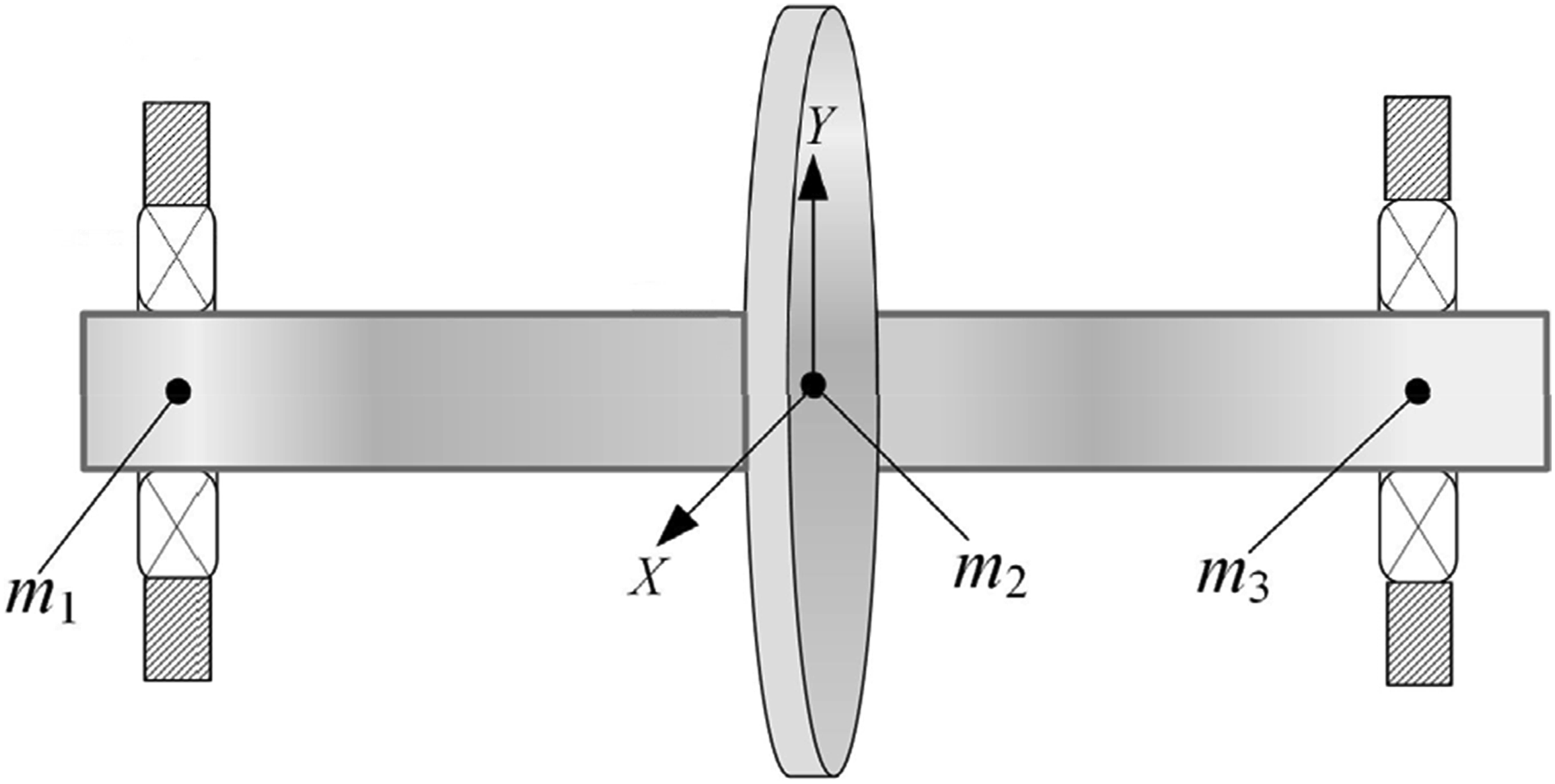
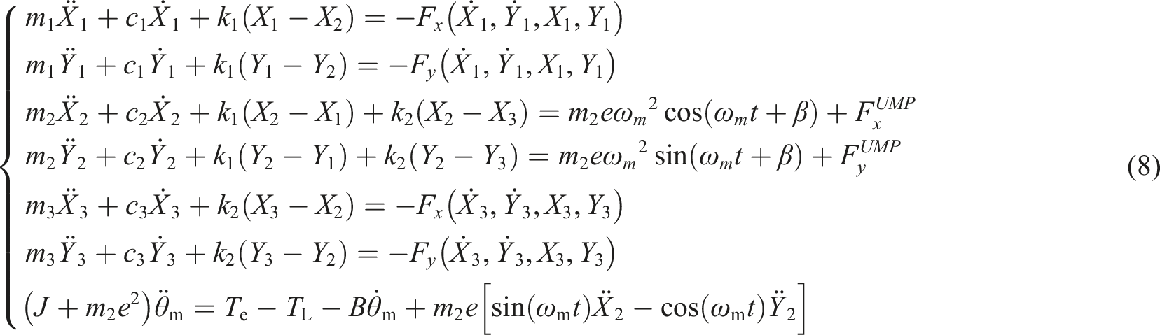
The notation Fx and Fy represents the bearing forces acting on the input and output shafts in the x and y directions within the inertial coordinate system, respectively. For a detailed description and modeling of these bearing forces, please refer to literature.
28
It is noteworthy that when magnetic lines pass through the stator and rotor, they naturally shorten, generating a magnetic pull force.
29
If the air gap between them is uniform, the pull force on the rotor will be symmetrical, resulting in a net force of zero. However, the lateral displacement of the rotor leads to non-uniform air gaps, causing radial unbalanced magnetic pull (UMP), which ultimately affects the vibration characteristics of the MGS. Therefore, the UMP (
Bending-torsion coupling model of the GTS
This section primarily focuses on the dynamic model of GTS within MGS, providing a foundation for integrating the electromechanical coupling model of the MGS and conducting further research on the dynamic behaviors of system. As depicted in Figure 1, there is a pair of spur gears meshing within the gearbox. The pinion (driving gear) is powered by the motor and, in turn, drives the movement of the gear (driven gear), with the load direction aligned with the axis of the driven gear. Given the compact design of the integrated MGS and the short protrusion length of the shaft end, the 8 DOF model is employed here, as detailed in the author’s previous work. 31
Figure 3 depicts the physical model of the GTS. Assuming two gears as cylinders, the gear meshing relationship is substituted with gear mesh stiffness and damping. This model encompasses various parameters, including the input torque (T
I
) generated by the motor, the output torque (T
O
) of the load, the backlash (b), the torsional stiffness (k
I
, k
O
) and damping (c
I
, c
O
) of the input and output shafts, gear transmission error (e(t)), time-varying meshing stiffness (k(t)), and damping (c(t)), time-varying load ratio of the gears, and friction factors. 8 DOF dynamic model of GTS.
31
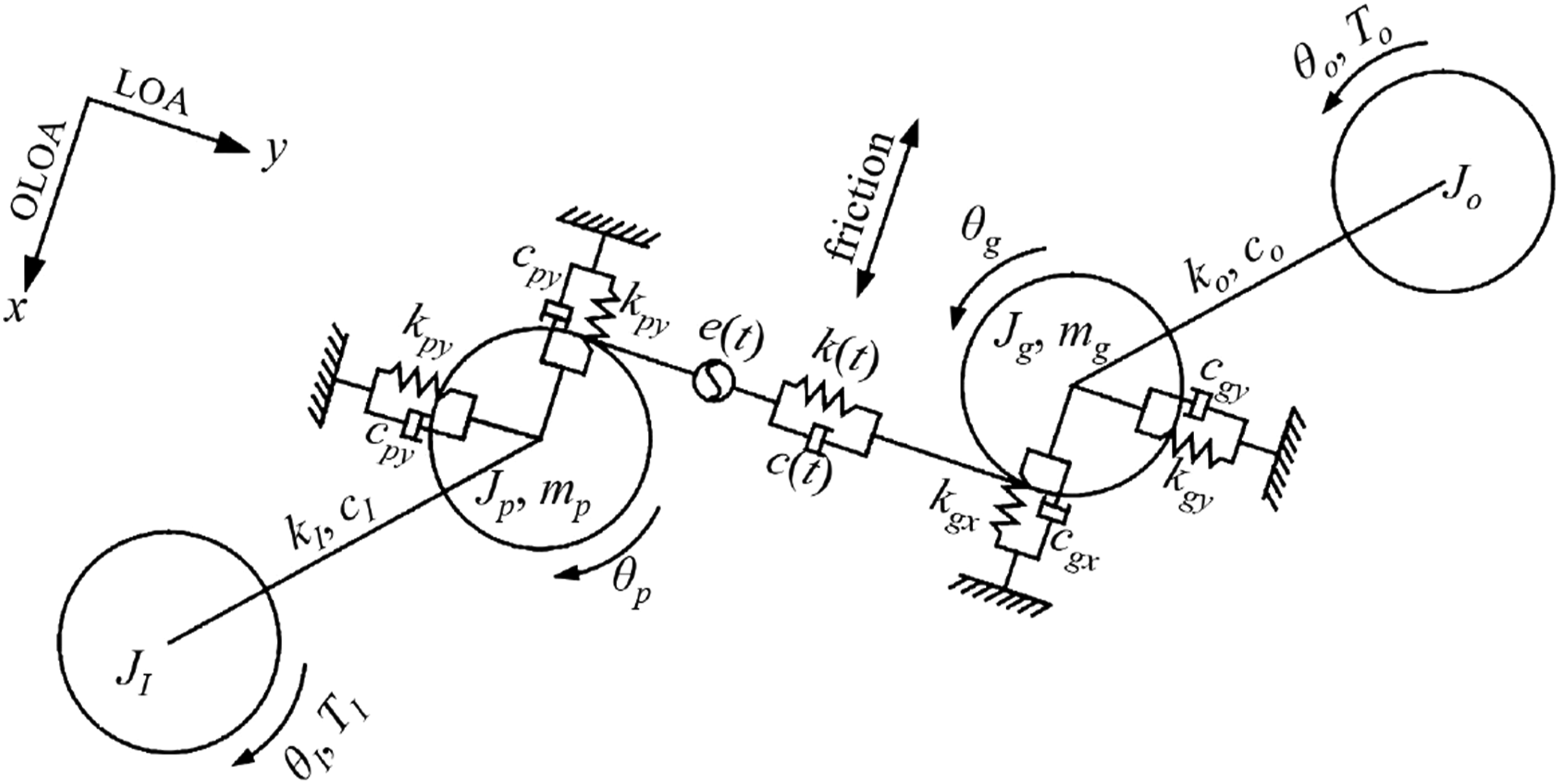
In Figure 3, J
i
represents the moment of inertia, where the subscript p corresponds to the pinion, the subscript g corresponds to the gear, the subscript I corresponds to the input, and the subscript O corresponds to the output. m
i
represents the mass of the gear, and θ
i
represents the angular displacement. Then, the gear dynamic equation is as

The aforementioned model entails the calculation of various excitation parameters, including gear mesh friction (F fi ), stiffness (k t ), friction coefficient, time-varying load distribution coefficient, and others. These parameters can be referenced from the author’s previous work. 31
Electromechanical coupling dynamic model of MGS
Figure 4 illustrates the global coupling relationship within the motor-gear system (MGS), depicting the power transmission sequence: the electrical drive initiates from the motor’s stator, generating a magnetic field that induces rotation in the rotor. This rotational motion is then transferred to the pinion, which drives the gear’s rotation. Finally, the gear transmits motion to drive the load. To align with modern mechatronic design demands, Figure 4 also incorporates motor control and mechanical control modules. These modules are essential for regulating and coordinating the operation of both the motor and mechanical system, ensuring optimal performance and functionality across various applications. The global coupling relationship of the MGS.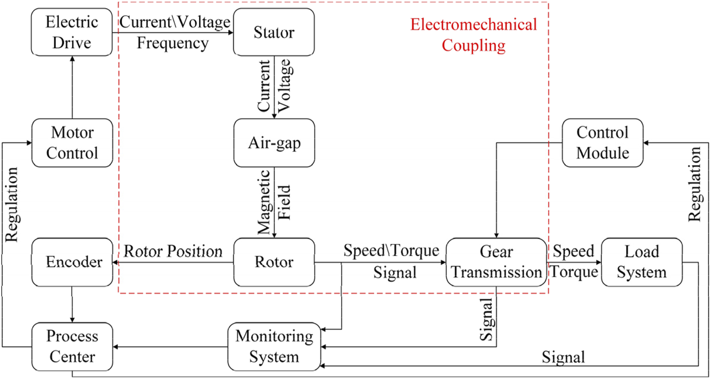
The power transmission relationship of the system allows for the extraction of coupling relationships between various sub-structures. In sections 2.1 to 2.2, separate mathematical models for the PMSM and GTS have been developed. Subsequently, based on the coupling relationship within the system, coupling channels between the PMSM and GTS are established, contributing to the creation of a multi-coupled dynamic model of the MGS under global coupling.
Figure 5 presents the global electromechanical coupling model of the MGS, incorporating inputs such as the specified motor given speed, three-phase voltage (u
a
, u
b
, and u
c
), and the load torque. The model outputs include the actual motor output speed, torque, actual motor three-phase current, and the motion state of each component. Comprising three main parts, namely the equivalent circuit model of PMSM, the mechanical model of motor rotor, and the bending-torsional coupling model of GTS, this model conducts real-time calculations within each simulation time step using their respective coupling parameters. Additionally, certain internal excitation parameters in the system rely on the calculated state quantities by the model. Consequently, the dynamic model acquired under global coupling facilitates the analysis of the dynamic response transmission relationship of power input among load output, GTS, or other mechanical structures. Global electromechanical coupling model of MGS.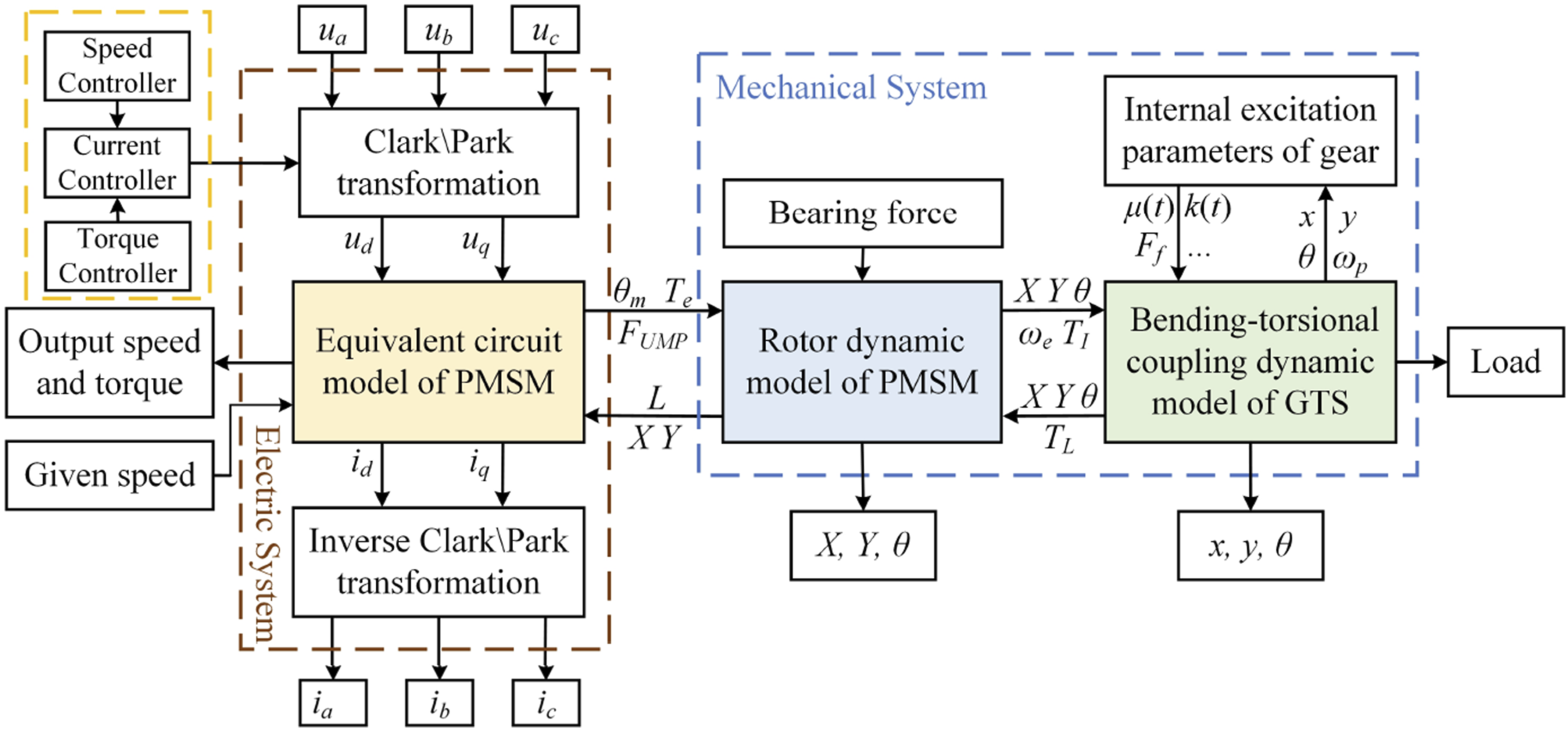
The electromechanical coupling dynamic modeling of the MGS has been finalized, encompassing various excitation parameters as illustrated in Figure 5. Although simplified calculations of excitation parameters can expedite modeling time, the accuracy of these parameters significantly influences the model precision and the efficacy of simulation results. Therefore, it is imperative to incorporate complex calculation methods for these parameters. Reference for these calculation methods can be found in previous work by the author and other researchers,30–32 covering aspects such as gear mesh stiffness and damping, the function of backlash, time-varying load ratio, tooth surface friction coefficient, and so on.
Vector-control of motor
While contributions have been made to studying motor control, the majority of research has been focused on controlling motor dynamic responses, with limited attention given to the impact of control technology on the entire MGS. Furthermore, factors such as parameter errors, vibrations, and uncertain external disturbances in the mechanical system have been ignored, resulting in inaccurate system modeling. However, achieving high-accuracy simulation results of motor control using an approximate model is challenging and may even lead to instability in the control system. Therefore, this paper aims to analyze the effects of different motor control technologies on both the dynamic of GTS and EDS, based on the electromechanical coupling dynamic model of MGS. To lay the groundwork for subsequent analysis, this section briefly introduces the design and parameter tuning of vector control. Vector control methods include proportional integral control (PI), sliding mode control (SMC), and proportional resonance control (PR).
As depicted in Figure 6, the flow chart illustrates the control process. This process primarily comprises two modules: the speed controller and the current controller. Building upon this control process, various control methods are introduced for the design of both speed and current controllers. The review includes the PI speed controller, PI current controller, SMC speed controller, and PR current controller, as outlined below. Principal diagram of PMSM control.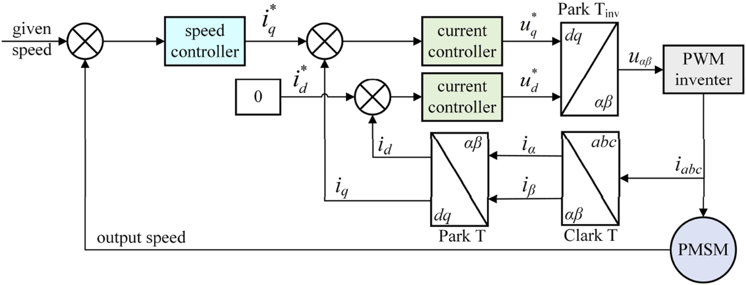
Review of PI speed controller
The PI speed controller, a conventional control scheme widely employed in diverse industrial control applications, incorporates an integrator. Its primary objectives include advancing control operations, minimizing stability errors, and adjusting the proportional gain to attain a steady state. The deviation between the actual output speed and the desired speed serves as the input for the PI controller (Kifayat et al, 2022)
33
. Further details regarding the PI speed controller are provided below

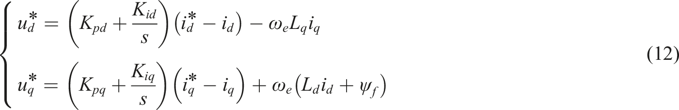
Review of PI current controller
Utilizing conventional PI controllers and integrating a feedforward decoupling control strategy enables the acquisition of voltage in the q-d reference frame
34
According to the internal model control design procedure, the controller is selected
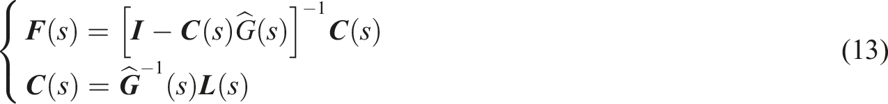

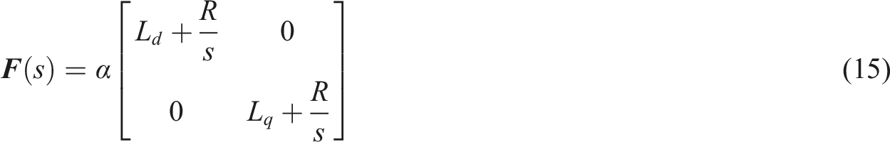
Combining equations (13)–(15), we can obtain

By comparing the equation (16) with the equation (12), it is evident that the number of controller tuning parameters has been reduced from 2 to 1, thereby reducing the complexity of parameter tuning. This adjustment satisfies the following relationship
The rise time (TR) is defined as the response time required for the system to react from 10% to 90% of the step, then the relationship between α and TR is approximately defined as TR = ln9/α. From the correlation between α and TR, it is evident that decreasing α will lead to an increase in response time, while increasing α will accelerate the response of system. However, α cannot be increased indefinitely. In the practical operation of the motor, the response time of system is constrained by the electrical time constant. The control parameter α selected in this paper is 1500.
Review of SMC speed controller
To facilitate the design of the speed controller for the surface PMSM, setting i
d
= 0 in the direction of the rotor magnetic field can achieve better control effects. The mathematical model of the PMSM in Section 2.1 is represented in q-d reference frame as
The state variable of control system is defined as

Derivation of above the equation can be obtained
Let

The sliding surface is given as


Then the exponential reaching law is adopted here


The stability of the designed sliding mode velocity controller is verified below by constructing a Lyapunov function
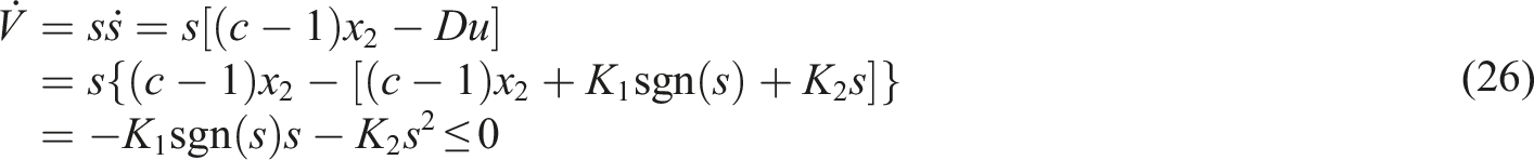
It is evident that K1 sgn(s) and K2 s2 are positive. Therefore, it can be proved that
Therefore, the reference current in the q-axis is expressed as

It can be observed from the above equation that the inclusion of an integral term in the controller not only attenuates oscillations but also eradicates steady-state errors in the system, thereby enhancing the control quality of the system.
Review of PR current controller
When utilizing feedforward decoupling PI control in the rotating q-d reference frame, vector control can accomplish decoupling control of the motor. However, variables such as motor inductance and resistance may fluctuate during motor operation, leading to magnetic saturation and temperature elevation. These fluctuations could induce deviations in the cross-coupling terms, thereby diminishing the control accuracy of systems. To address this issue, a current vector control strategy based on proportional resonance (PR) control is introduced. 34
The transfer function of the PR controller is


Observing equation (30), the quasi-PR controller consists of three design parameters: K
p
, K
i
, and ω
c
. When employing the quasi-PR controller, to simplify the discrete process, only the resonant controller is discretized in this context. This discretization can be achieved using a bilinear transformation, with the transformation formula being

Substituting equation (31) into equation (30) gives

Combining Equations (30)–(32), the difference equation of quasi-PR controller

Experimental verification of dynamic model
To address the electromechanical coupling dynamics of the MGS, the previous section presented a comprehensive dynamic model of the MGS. Subsequently, in order to ascertain the accuracy and efficacy of the enhanced dynamic model, experimental validation based on an experimental test platform is provided.
Introduction of experimental platform
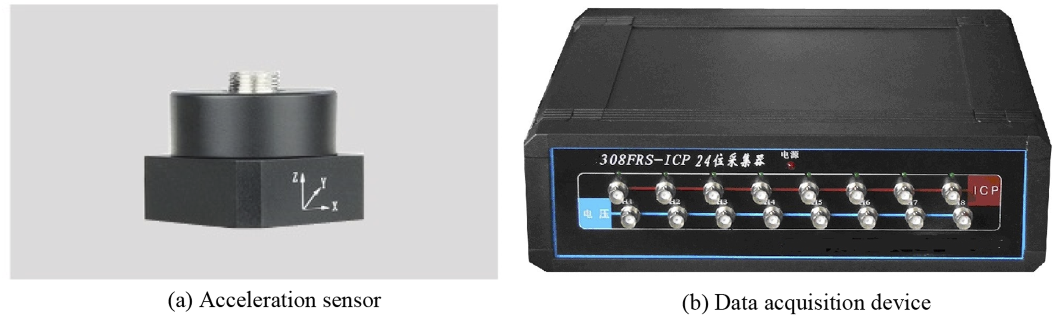
Figures 7 and 8 illustrate the experimental test platform, which comprises a gearbox, variable frequency AC motor, magnetic powder brake, acceleration sensor, data acquisition system, controllers, and other ancillary components. The AC motor is driven by the frequency converter, transferring power to the input shaft of the gearbox. The motor has a rated power of 1.5 kW, and its speed can be adjusted within the range of 0 to 1500 r/min. The load is applied by the magnetic powder brake connected to the output shaft, with the brake torque controlled by the brake controller within the range of 0 to 10 N·m. Experimental test platform of GTS: 1. Worktable; 2. Tachometer; 3. Speed controller; 4. PMSM; 5. Gearbox; 6. Vibration sensor; 7. Magnetic powder brake; 8. Brake control. (a) Acceleration sensor. (b) Data acquisition device.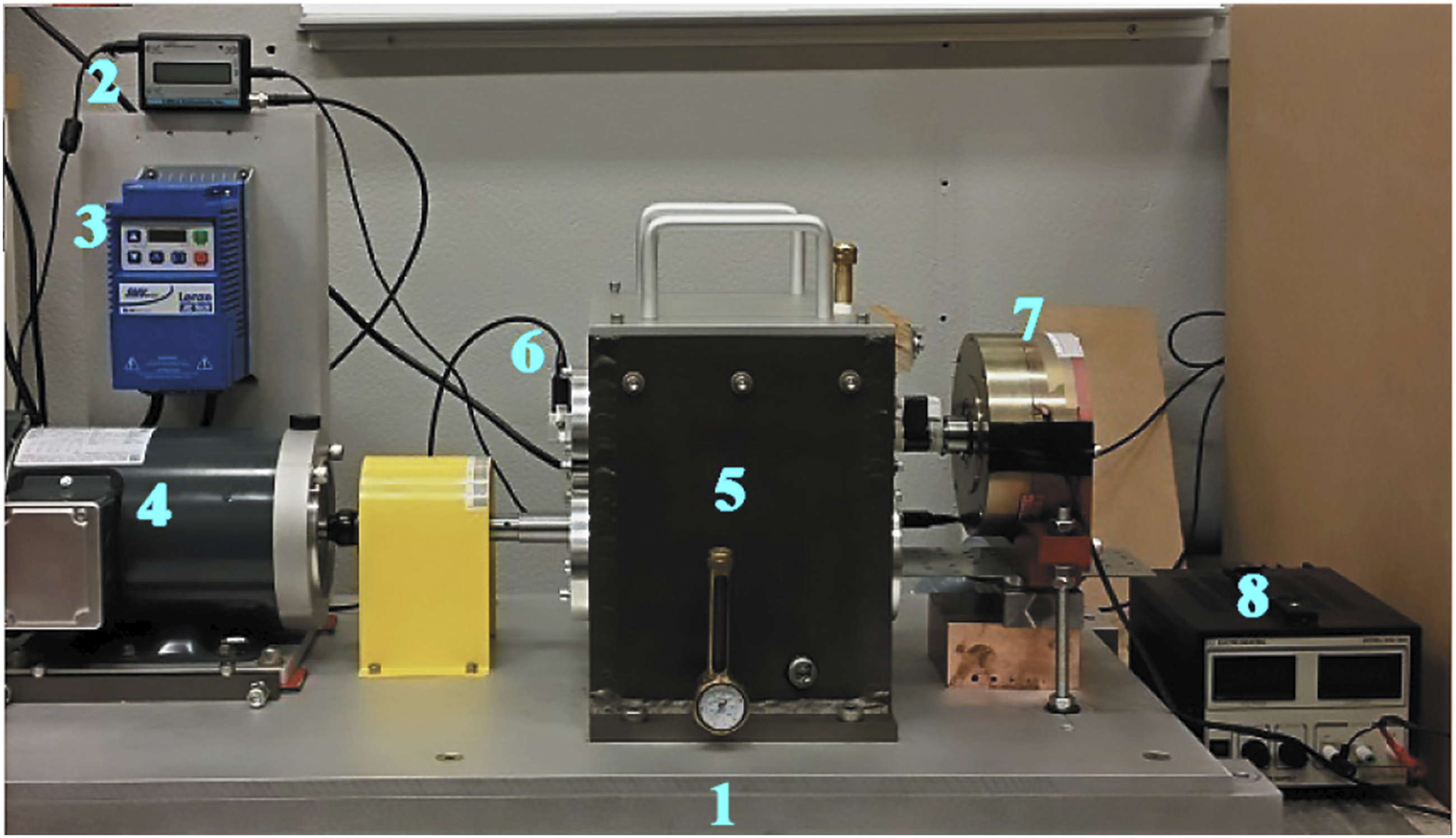
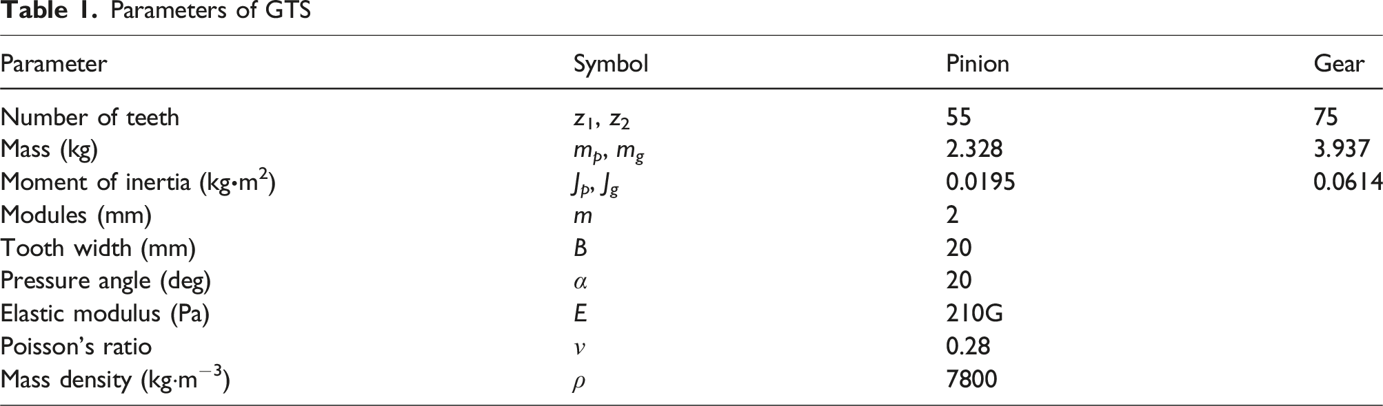
Parameters of GTS
Model verification
To validate the effectiveness of the electromechanical coupling dynamic model of MGS established in section 2, validation is conducted using the experimental test platform described above. The comparison results under different speeds are depicted in Figures 9 and 10. The experimental results consist of the vertical acceleration vibration signal of the gearbox input shaft, while the simulation results entail the lateral acceleration of the gear center. Both time-domain signals and corresponding frequency spectra are presented for analysis. Comparison of lateral vibration acceleration at rotational speed of 880 r/min: (a) Experimental results; (b) Simulation results. Comparison of lateral vibration acceleration at rotational speed of 1500 r/min: (a) Experimental results; (b) Simulation results.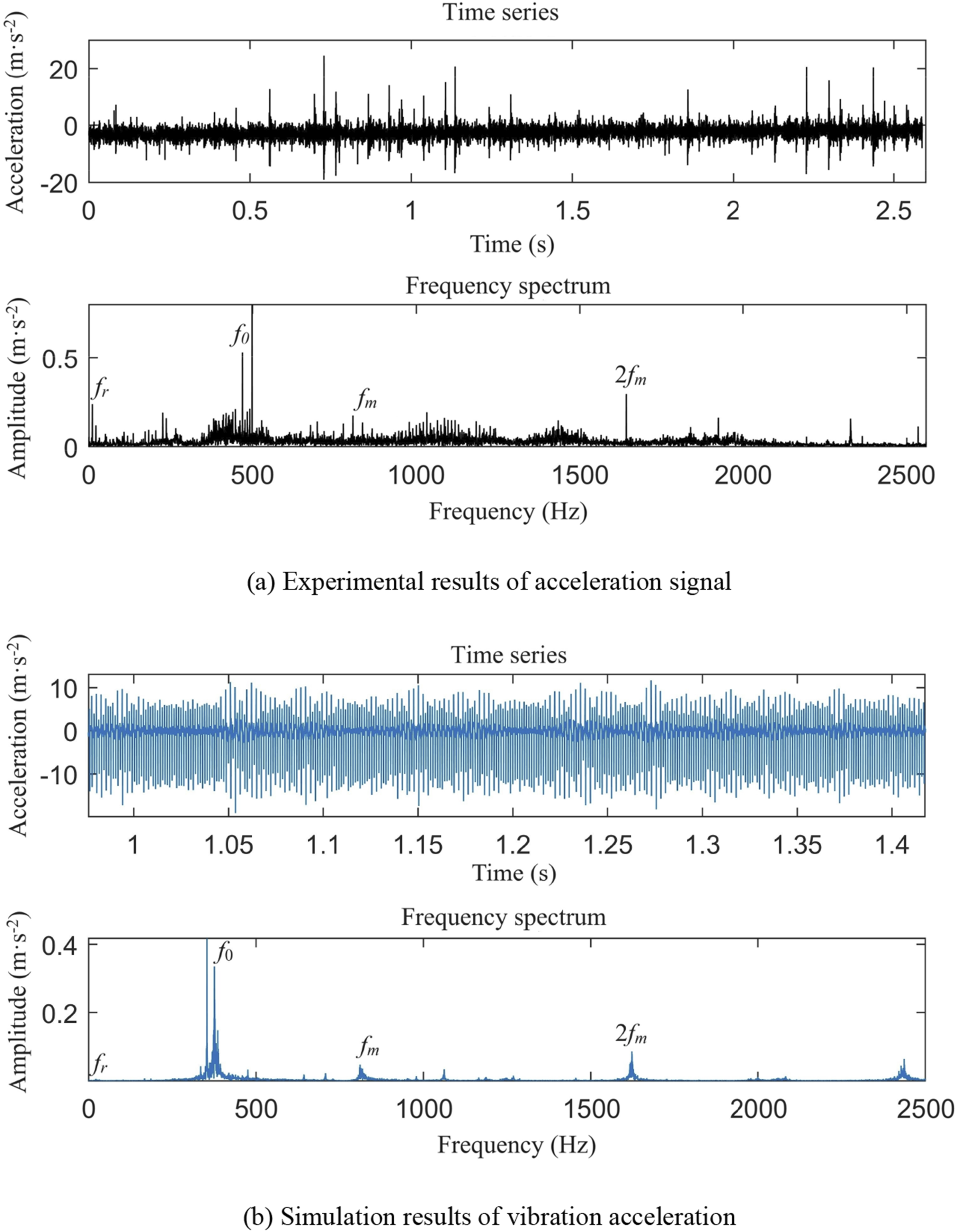
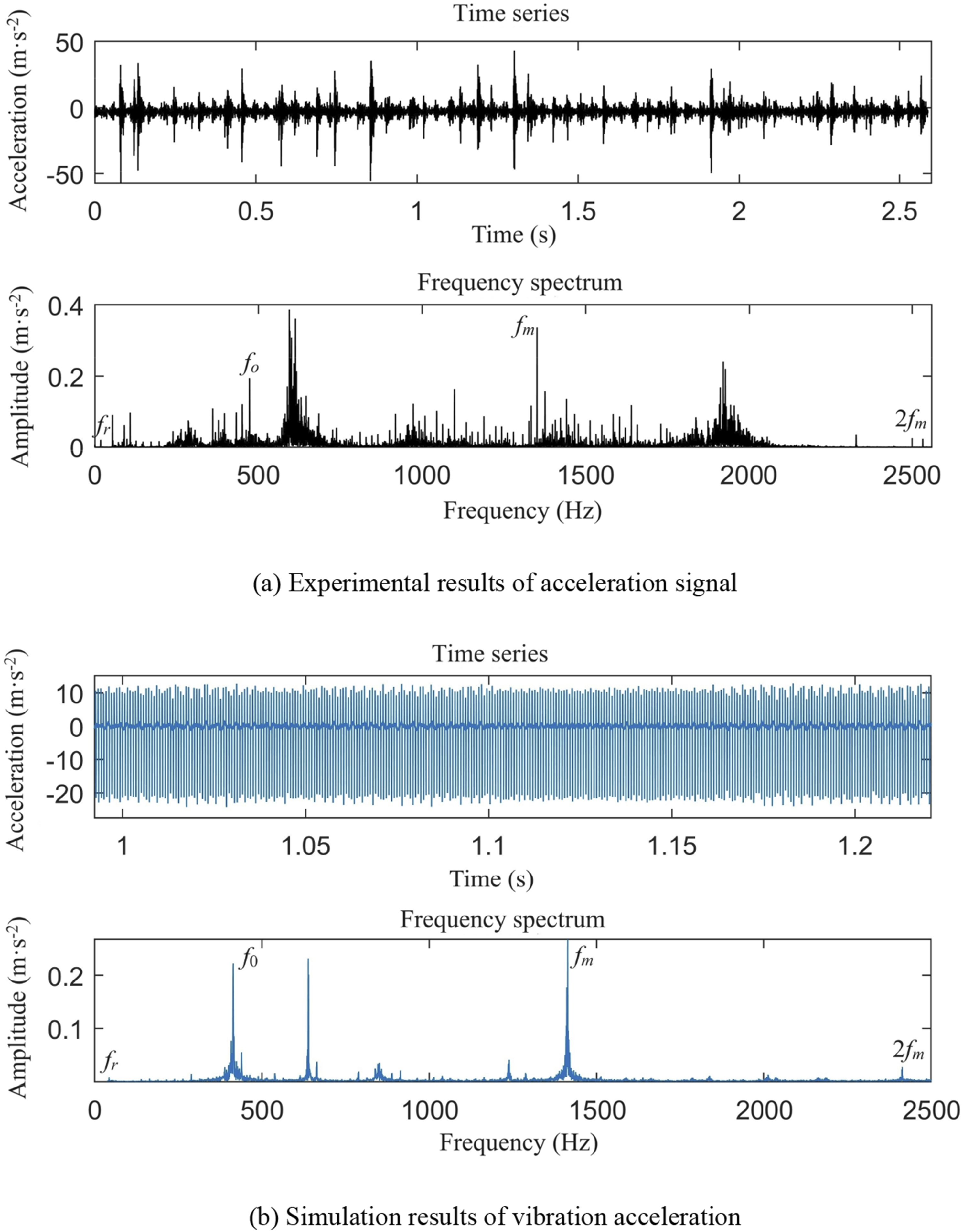
The vibration acceleration signal of the gearbox at 880 and 1500 r/min, as depicted in Figures 9 and 10, exhibits harmonic vibration patterns in the time-domain signal. However, the signal displays chaotic behavior, which hinders the direct identification of fluctuation periods or extraction of meaningful features. Analysis of the frequency spectrum of the experimental signal reveals the presence of three primary frequencies: the rotational frequency (f
r
), the meshing frequency (f
m
), and twice of the meshing frequency (2f
m
), accompanied by dense sidebands near these primary frequency components. The comparison between the simulation and experimental results highlights several key findings:
Overall, while the simulation results offer valuable insights into the dynamic behavior of system, it’s important to acknowledge the limitations of the idealized model in comparison to the complexity of real experimental setups. Adjustments and validations may be necessary to enhance the fidelity of the simulation model for predictive analysis and design optimization purposes.
Simulation
Accurate system modeling is crucial for implementing effective control methods. Utilizing approximate models presents considerable challenges in achieving high-performance motor control and may even lead to unstable behavior. To address these challenges, this section adopts the electromechanical coupled dynamic model of MGS to examine the effects of motor control methods on dynamic behaviors of MGS. Building upon the analysis presented in section 2.4, an evaluation and comparison of these control strategies are conducted to assess their effects on dynamic response of both the EDS and GTS. This comprehensive approach aims to improve our understanding of the interaction between motor control technologies and the broader dynamics of the MGS. Thereby, it provides a theoretical basis for enhancing control methods and optimizing system performance. Figures 11–13 illustrate a comparison of motor responses under various motor control techniques. Comparison of actual motor output speeds under different motor control techniques. Comparison of actual motor output torques under different motor control techniques. Comparison of motor current responses under different motor control techniques.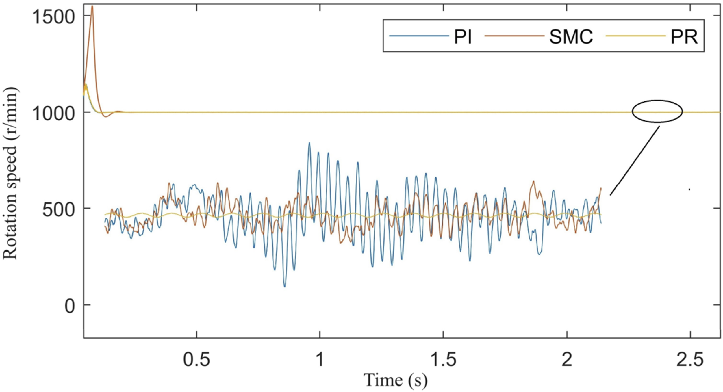
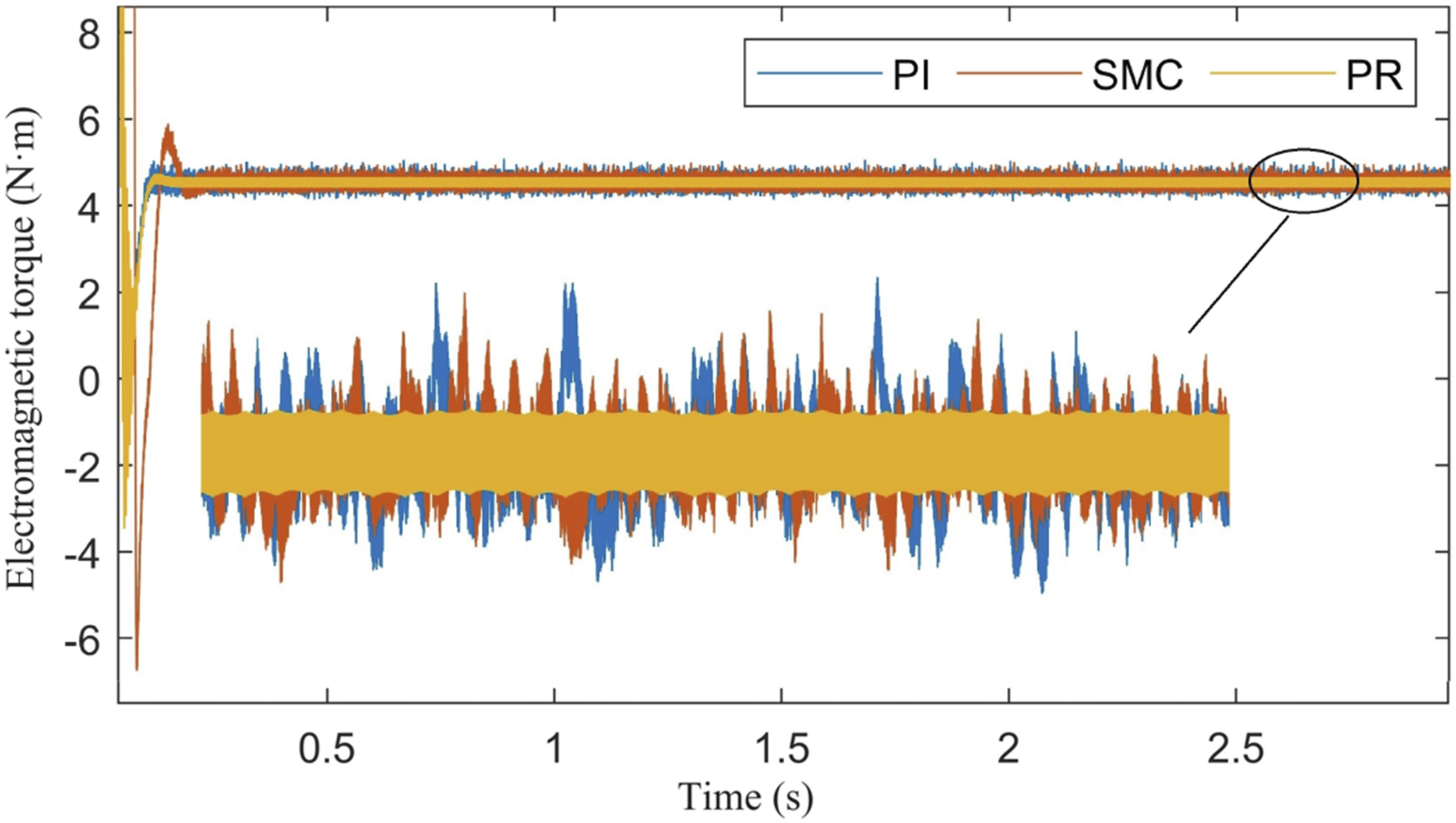
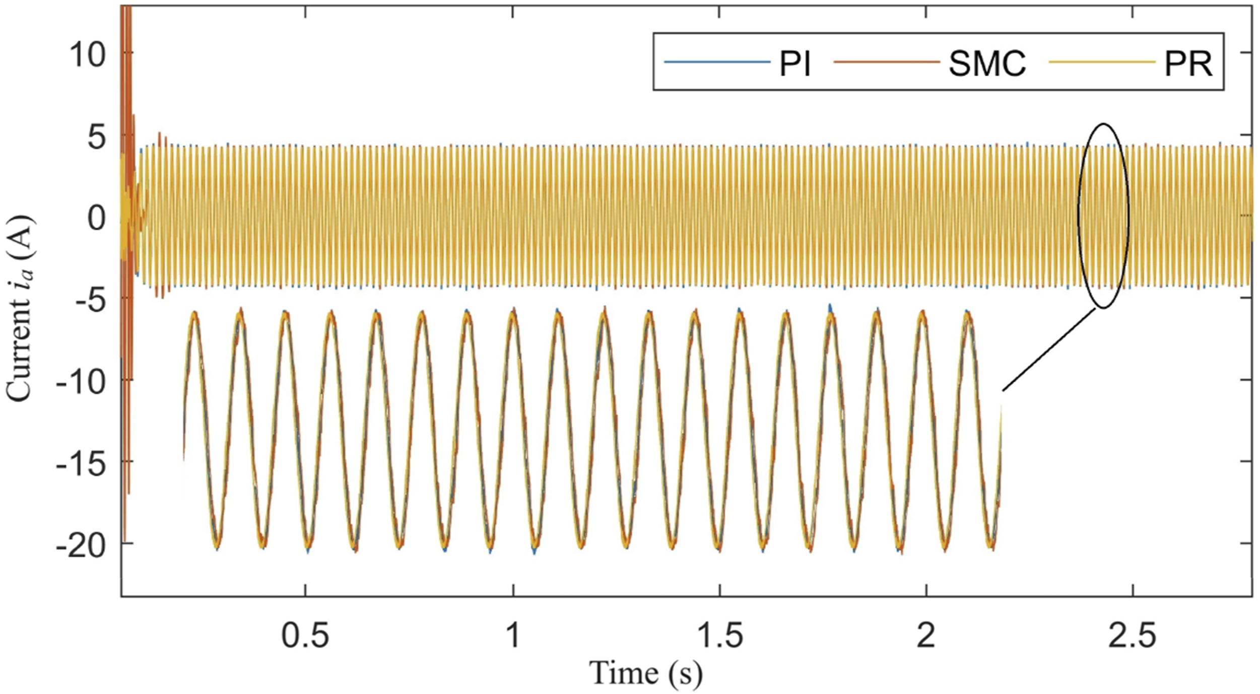
In the context of speed control (Figure 11), the effectiveness of different motor control methods in regulating motor speed is evaluated. It is observed that the given speed is rapidly achieved across different control approaches. Notably, SMC demonstrates more pronounced speed fluctuation compared to PI control, and PR control for current loop regulation results in reduced speed fluctuation. Moving to torque control (Figure 12), all three control techniques showcase swift stabilization of motor output torque. However, PR control technology exhibits minimized fluctuation in motor output torque compared to alternative methods. Examining current control (Figure 13), PR control technology demonstrates the fastest stabilization of motor operating speed, implying a swifter response than PI control. Additionally, the utilization of SMC control and PR control leads to enhanced current fluctuation. The application of the electromechanical coupled dynamic model of MGS during the design phase proves beneficial for comparing and fine-tuning control effects. Simulation outcomes closely correspond with actual technological characteristics, affirming the effectiveness of applying motor control techniques to the proposed model.
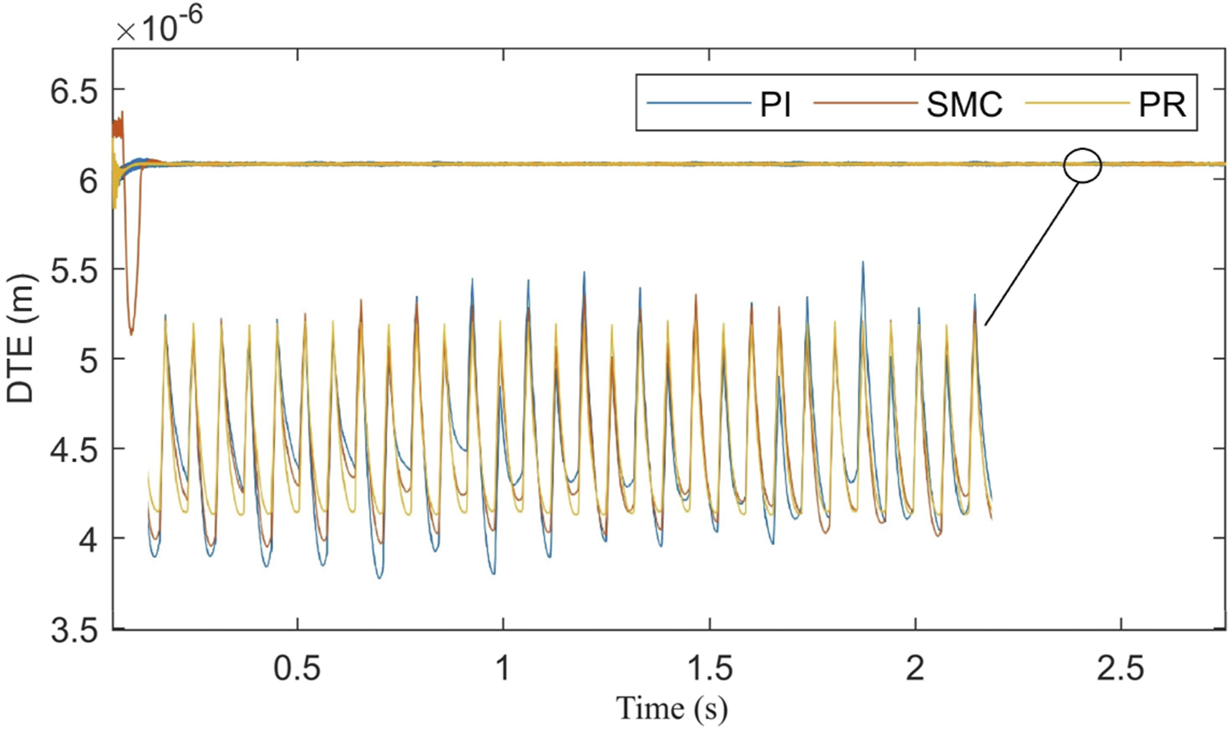
The research findings presented above demonstrate that through the utilization of the proposed model of MGS, it is possible to investigate the effects of different motor control techniques on the dynamic response of both the EDS and GTS. As shown in Figure 14, a comparison of displacement responses along the meshing line direction of the gear under different motor control techniques is presented. The graph illustrates that both SMC control and PR control can reduce the amplitude of gear vibration. However, upon closer examination in the zoomed-in detail graph, it is evident that PR control exhibits the best performance. This superior performance is attributed to the smaller fluctuations in motor output speed and torque under PR control, thereby reducing the disturbance effect on GTS and further enhancing its dynamics. Figure 15 presents a comparison of gear dynamic transmission error (DTE) under different motor control techniques. The graph indicates that SMC and PR control techniques perform well in terms of DTE dynamic response. Further scrutiny in the zoomed-in detail graph reveals a certain “tip chipping” effect on the response fluctuation of DTE exhibited by these two control strategies. Comparison of yp under different motor control techniques. Comparison of DTE responses under different motor control techniques.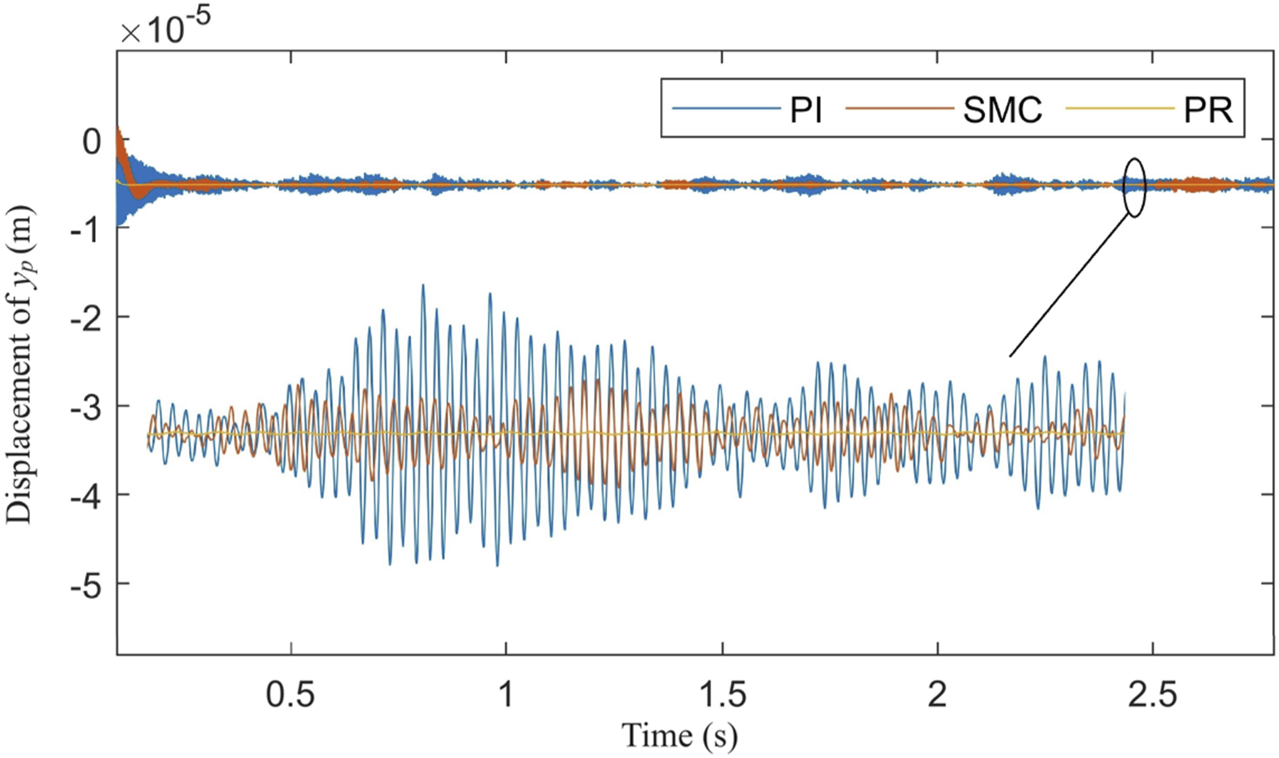
The research on the effect of various motor control techniques on system dynamic characteristics suggests that motor control technologies have the potential to improve the dynamic characteristics of the EDS and mitigate vibration in the GTS, thereby enhancing system output performance. Regarding control effectiveness, the current loop controller designed using PR control noticeably outperforms the PI controller. Similarly, the speed loop controller based on SMC strategy surpasses the PI controller. However, in terms of control strategy design and parameter tuning, the PI controller has only one control parameter, making the tuning process simple, whereas parameter tuning for the other two control strategies is relatively complex.
Conclusion
The electromechanical coupling dynamic model of MGS is key for understanding interactions between GTS and EDS. The proposed model in this paper is vital for designing effective motor control systems, enabling optimization of performance factors like speed stability, torque control, and current response. It helps predict and manage the dynamics of the electric drive system. In conclusion, the research underscores the importance of understanding the dynamic interactions between the EDS and GTS, emphasizing the pivotal role of appropriate control techniques in optimizing system performance. The main conclusions are summarized as follows: 1) The proposed electromechanical coupling dynamic model of the MGS not only improves modeling accuracy but also exhibits broad applicability, while balancing accuracy and efficiency. 2) The effectiveness of the proposed model is validated by comparing experimental results with simulated results, demonstrating that the established model accurately captures the dynamic behaviors of MGS. 3) The proposed model can be utilized to investigate the effects of different motor control techniques on the dynamic behavior of MGS. Motor control technologies hold the potential to improve the dynamic responses of the EDS and reduce vibration in the GTS.
Footnotes
Declaration of conflicting interests
The authors declared no potential conflicts of interest with respect to the research, authorship, and/or publication of this article.
Funding
The authors disclosed receipt of the following financial support for the research, authorship, and/or publication of this article: The work is supported by National Key Research and Development Program of China (2023YFB3406601), Major Research Plan (52275055), and Industry Cooperation of Major Science and Technology Project of Fujian Province (2022H6028).