
Abstract
With the metro vehicle as the subject, a mathematical model of the main chamber, the auxiliary chamber and the orifice of the air spring were established based on the thermodynamic theory. The lateral nonlinear model is obtained based on the analytical geometry. Establish the four-point levelling valve and differential valve models through theoretical analysis. A complete three-dimensional air spring model is established. The correctness of the model is verified by comparing it with the actual data. The impact of orifice diameters and secondary vertical dampers on the dynamic performance of the metro vehicle is investigated. The results show that the secondary vertical damping configuration has a greater effect on vertical stability and acceleration but a minor impact on operational stability. Metro vehicles equipped only with air springs in the smaller diameter orifice do not need to be configured with a vertical damper, resulting in excellent dynamic performance and savings in production costs.
Introduction
Due to the considerable load variation of metro vehicles, the air spring ensures the consistency of vehicle floor height and running stability. It has been widely used in motor train unit (EMU) vehicles. 1 The orifice is located between the additional chamber and the main chamber. When vertical deformation occurs, the pressure difference between the two will be generated, making the air pass through the orifice and produce a specific resistance to dissipate part of the energy to achieve the effect of vibration reduction. The fixed orifice is simple in structure and hardly increases the cost of the air spring. It is generally used in vehicles with low speeds. Using an orifice or oil vertical damper to provide vertical damping depends on the air spring structure and working characteristics. Due to the low speed of subway operation, studying the running performance of air springs and the orifice is necessary.
Air spring suspension has complex nonlinear characteristics. Modelling and specific parameter analyses have always been difficult research points. The modelling of air springs can be classified into four categories: mechanical model, thermodynamic model, analytical model, and finite element model. 2 The application scope and ideas of each method are different. The mechanical model is mainly expressed by equivalent damping, equivalent stiffness or other elements, and the parameter values are often derived from experiments. Because of its simplicity and rapidity, it is currently most widely used in multibody dynamics. The most widely used are ‘Nishimura linear model’, 3 ‘SIMPACK FE83 model’, 4 ‘Vampire model’, 5 ‘Berg model’ 6 and the corresponding improved models.7–9 The thermodynamic model10–12 uses the laws of mechanics and thermodynamics to describe the physical processes in motion. Various models are discussed, compared, and verified by experiments.13,14
However, many thermodynamic models only focus on vertical performance and ignore lateral characteristics. In addition, the physical input parameters of the model need to be obtained through experiments. Docquier proposed a relatively complete thermodynamic model in his thesis. 15 The analytical model16,17 is based on the geometric analysis and the geometric changes produced by the air spring under specific conditions (usually requiring assumptions and simplification). The finite element model18,19 is the most accurate. The model is accurate and parameterisable, but the simulation cost becomes enormous. Compared with other methods, the current application is less. It is often used to determine the specific physical parameters of thermodynamic models.
Many scholars have researched air springs’ vertical and lateral nonlinear characteristics and orifice damping characteristics. Qi et al.20,21 established the mathematical models of the main chamber, additional chamber and orifice considering the rubber balloon friction. It analysed the vertical stability of the nonlinear air spring through joint simulation. The transverse restoring force model is established by analysing the balloon’s stress. Li et al. 22 studied the effect of key parameters through analytical geometry. Li et al. 1 established the mathematical model based on thermodynamics and hydrodynamics theory and analysed the main influencing parameters. Wu et al. 23 analysed linear and nonlinear and equivalent models’ running stability under straight lines and curves of air springs. Wu et al. 24 identified critical parameters and studied their influence on dynamic performance. Chen et al. 25 established a nonlinear model and analysed the influence of rubber balloons on air springs. Quaglia et al. 26 established a dimensionless mathematical model with an orifice and additional chamber and analysed its vibration characteristics. Alonso 27 studied the effect of air spring and orifice size on vehicle comfort. The modelling of air springs is mainly studied from each sub-component without establishing a complete three-dimensional model. Only single vertical or horizontal characteristics are studied. The research object is mainly high-speed EMUs, with less research on the metro.
This paper mainly consists of three aspects. Firstly, the complete air spring nonlinear models were built based on the previous research theory. 28 Secondly, the model’s validity is tested by simulating the lateral and vertical characteristics, which agree with the experimental data. Finally, taking the metro vehicle as the research object, the influence of orifice and external vertical damper on vehicle dynamics are studied. The results show that the established complete nonlinear air spring model is feasible. The orifice of metro vehicles can be set to a smaller diameter without an external vertical damper, which can meet vehicle operation requirements and save the cost of design and parts purchase.
Three-dimensional dynamic models of air spring
Figure 1 illustrates the working principle of the air spring pneumatic system. Air enters the main and auxiliary chambers by the levelling valve; the orifice plays a damping role at this time. When the differential pressure of the air spring reaches a specific value, the differential valve will be connected and play a role. Only the air spring fails, and the emergency rubber spring comes into play. Air spring pneumatic system.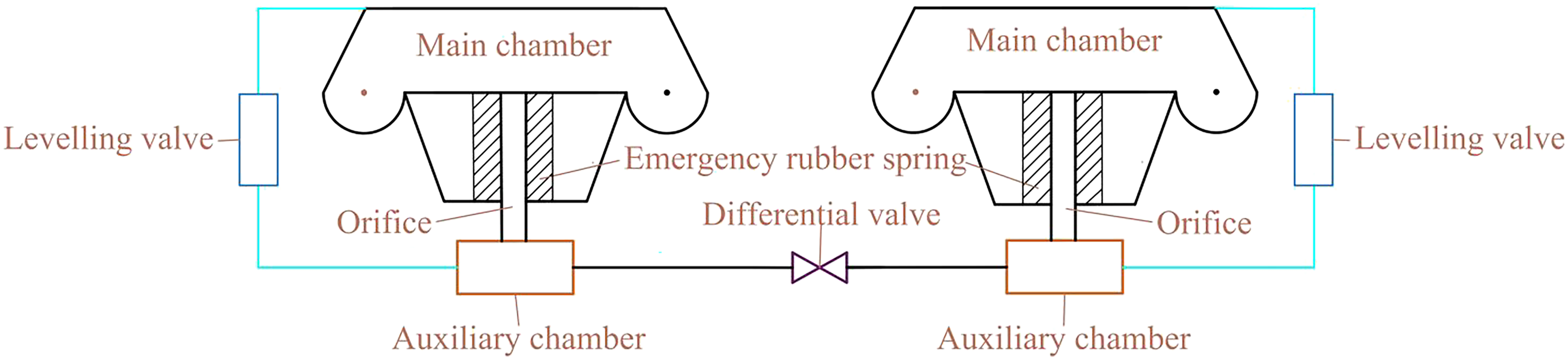
Main chamber and auxiliary chamber models
During metro operation, the frequency of vehicle vibration is relatively high. When the air spring is stressed, it will affect the volume, pressure, and stiffness of the main chamber and the stiffness of the auxiliary chamber. That is what this Section is all about. It is assumed that there is no heat exchange between the rubber balloon and the outside during the whole vibration process, and the gas meets motion equation under adiabatic state as follows

Equation (2) is derived from the derivation of time by equation (1), as follows

The volume is related to its working height h, lateral displacement

The effective area of the main chamber is a function about h,

Relative pressure of the main chamber

The reaction force of the main chamber


Orifice model
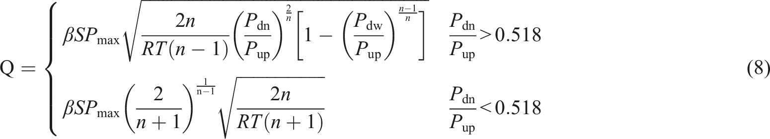
The orifice is an important damping structure which restricts and hinders the gas flow between the main chamber and the additional chamber. Based on hydrodynamics theory, the gas flow through the orifice is subject to the pressure difference between the main and additional chambers. Due to fluid friction and inertial forces, the effective flow area of the orifice needs to be considered in the calculation. Q represents the gas mass flow through the orifice
29
Emergency rubber spring model
When the air spring is broken for other reasons, the top plate directly contacts the emergency rubber spring to prevent rigid contact between the vehicle body and the bogie. Under the regular operation of metro vehicles, emergency rubber springs have little effect. The supporting effect of the emergency rubber spring can be considered only when the air spring fails.
The rubber balloon is connected in series with the emergency rubber spring during regular work, and emergency rubber spring stiffness can be almost ignored. When the air spring fails, the stiffness of the emergency rubber spring can be linearised. The vertical support reaction force of an emergency rubber spring is calculated as follows
30

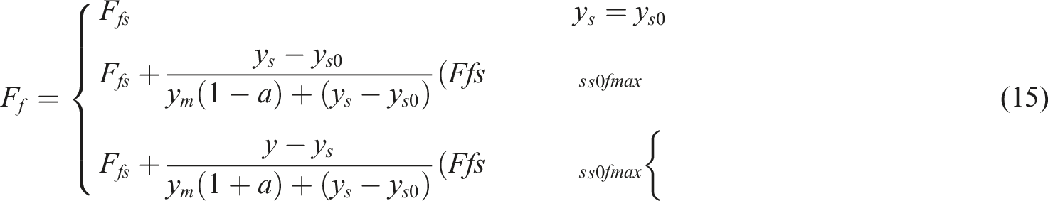
A transverse nonlinear model of air spring
Analytical geometry is used to study the lateral behaviour of the air spring. When the lateral force pushes the air spring, the left and right rubber balloons deform, affecting the contact area between the car body and the air spring. The metro vehicle equips the rolling lobe air spring, and rubber balloon friction is also generated during lateral movement.
Figure 2 shows that when a right lateral force pushes the air spring, the centre of the left rubber balloon arc rises from the O
A
point to the O
B
point. The centre of the right rubber balloon arc drops from the O
C
point to the O
D
point. The deformation of the rubber balloon can be assumed to be projected into an oval area. The rubber balloon will bend when the transverse force pushes the air spring. Where Transverse deformation.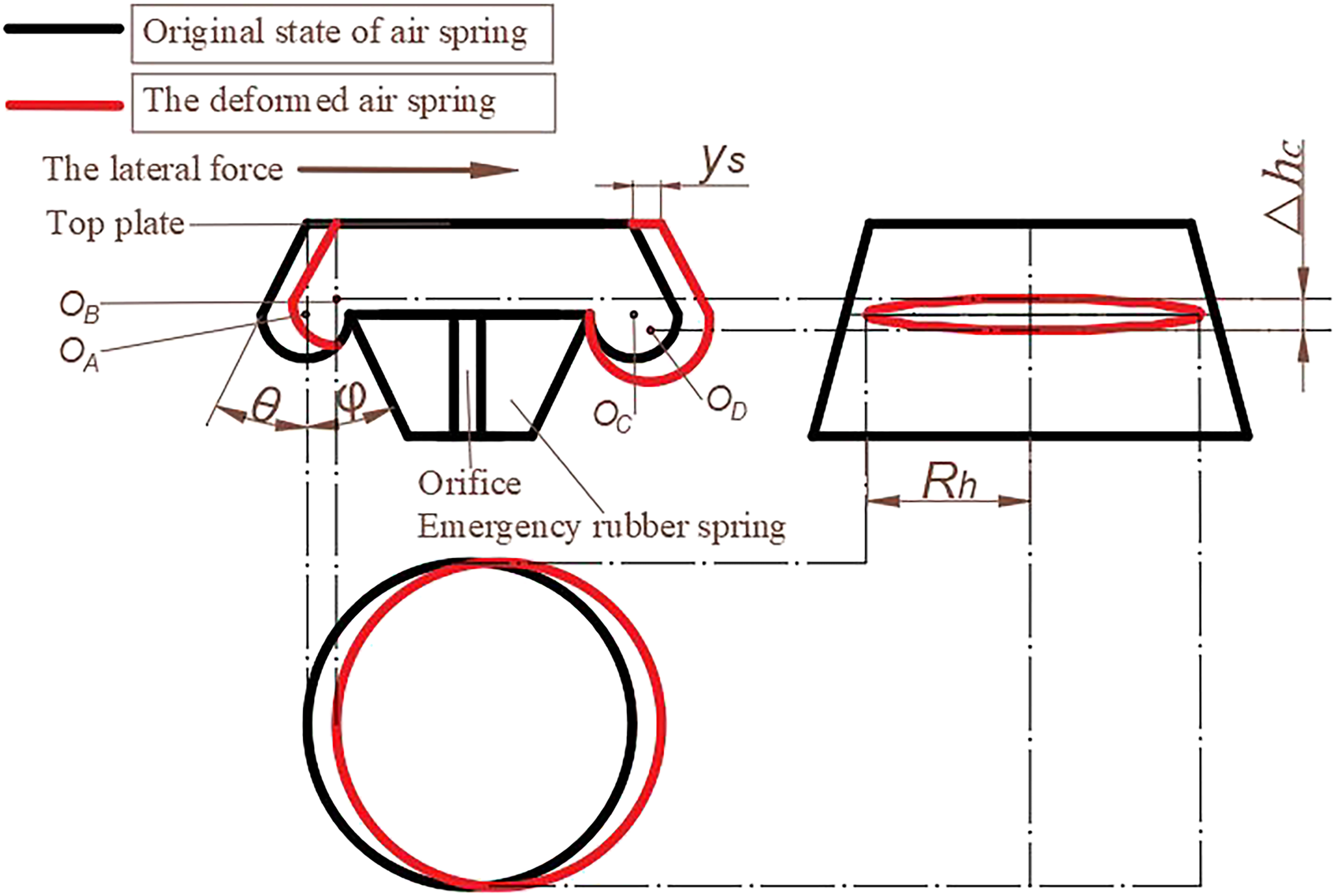
The lateral nonlinear model contains two parts: one is the aerodynamic force obtained by multiplying the air spring pressure and the effective area


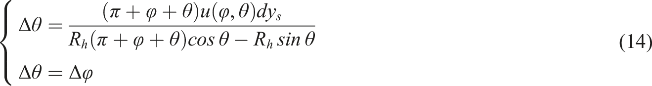
It is assumed that the circular arc deformation of the rubber balloon on both sides is the same, and the internal and outer angles change equally. Substitute equation (12) and equation (13) into equation (11) is as follows
Under lateral force, the top plate is in friction contact with the rubber balloon, and the balloon is deformed. A specific friction force and linear elastic force will be generated within the material, and the friction model can express its hysteretic characteristics. General friction models include Maxwell and Coulomb friction models. Due to the low smoothness of the Maxwell model, which is unable to reflect the nonlinear properties of rubber, the Coulomb friction model is adopted in this section, which is expressed as
31
Levelling valve model
The four-point levelling configuration refers to a bogie with two sets of levelling valves on the left and right air springs and the auxiliary chambers not connected, that is, with differential pressure installed between the auxiliary chambers. The mathematical model of the four-point levelling configuration of a metro vehicle is expressed as follows
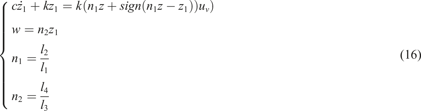
According to the theory of fluid mechanics, the flow rate of air spring during charging and discharging is not only related to the diameter of the orifice but also depends on the pressure ratio. It can be calculated by the following equation (17)
30
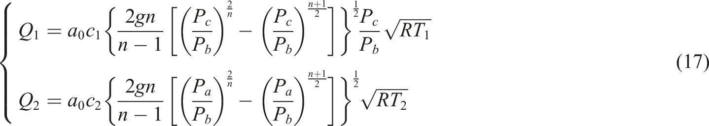
Differential valve model
The differential pressure valve is a safety device that ensures the pressure difference between the air springs on both sides of the bogie does not exceed the specified value. The differential valve will automatically open when the pressure difference is too large. The gas flow to and from the additional chamber

The differential valve model can adopt equation (8) of the orifice for similar calculation. The differential pressure on rail vehicles is mainly in the 0.1 ∼ 0.2 MPa. 32
Co-simulation
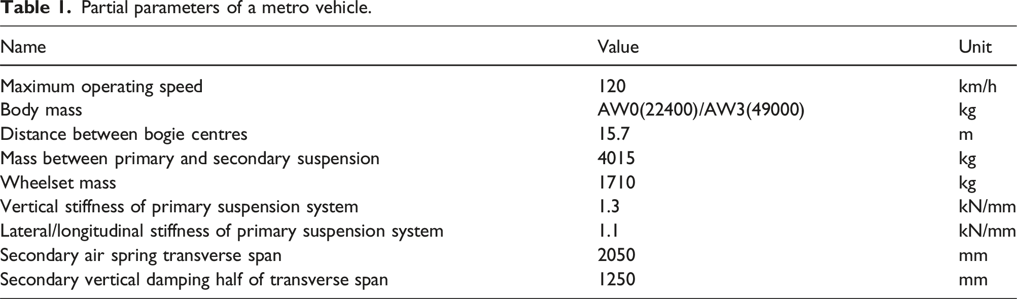
Partial parameters of a metro vehicle.
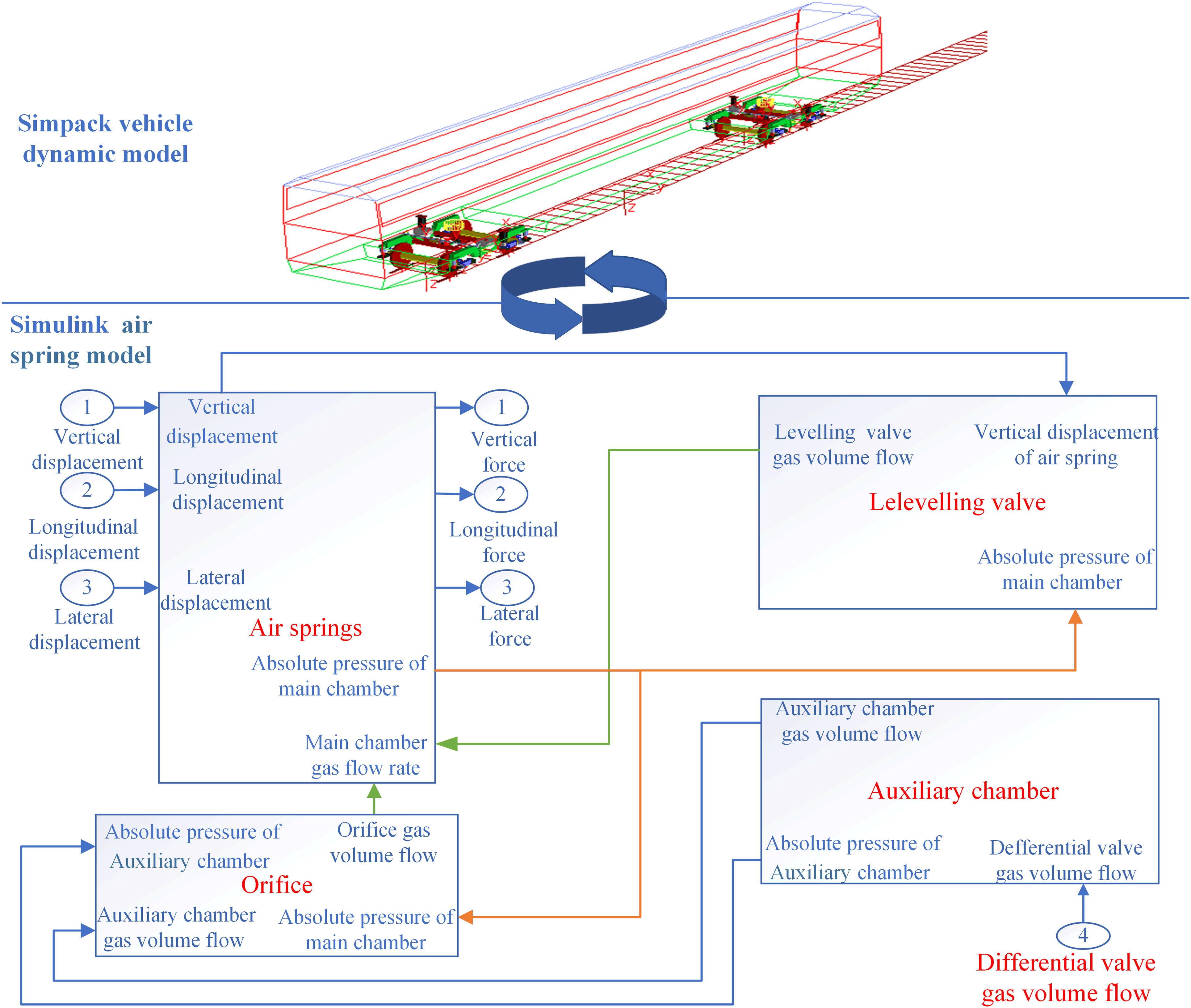
Co-simulation diagram.
In real-time, Simpack transmits the working height and lateral and longitudinal displacement data to the three-dimensional air spring model in Simulink. The vertical, lateral, and longitudinal support forces are calculated in Simulink and then transmitted to Simpack to calculate the real-time movement of metro vehicles, generating new working height data and lateral and longitudinal displacement data. The two exchange data in the real-time cycle until the end of the simulation.
Model verification
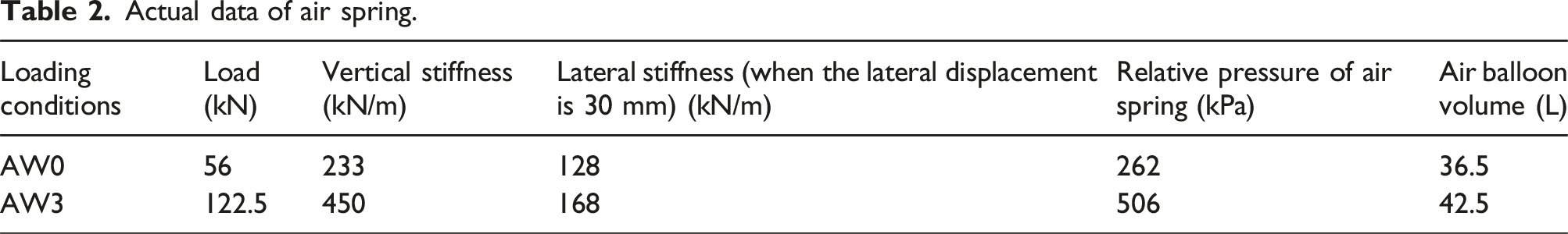
Actual data of air spring.
Firstly, the vertical performance of the air spring is verified. Apply 56 kN, 122.5 kN, and 10 mm amplitude excitation to the air spring, as shown in Figures 4(a) and (b). Then, lateral performance is verified. The load is applied, as shown in Figures 4(c) and (d). Variation in load-displacement and stiffness-displacement curves (a) Vertical load-displacement (b) Vertical stiffness-displacement (c) Lateral load-displacement (d) Lateral stiffness-displacement.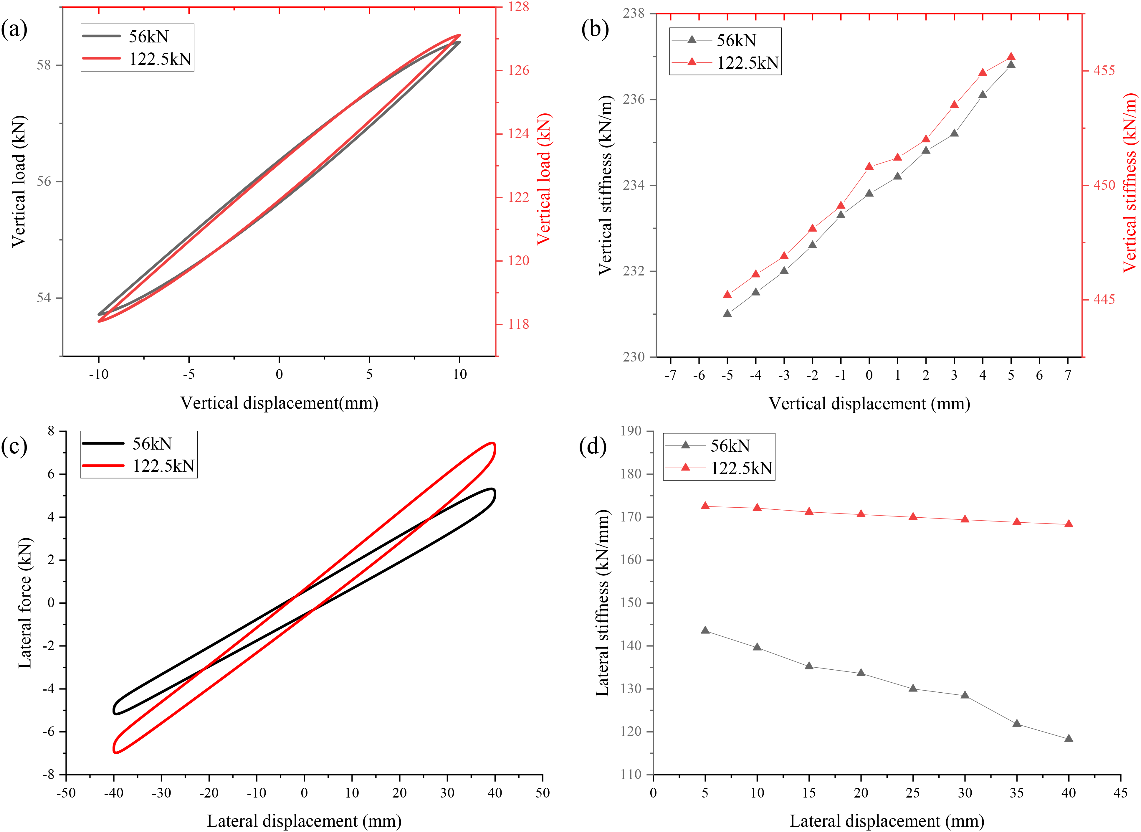
Figures 4(a) and (b) show that the variation in load-displacement curves of air springs under 56 kN load and 122.5 kN load are consistent with the vertical stiffness in Table 2. The vertical stiffness under 56 kN load is 233.8 kN/m, and the error is 0.34% compared with the given parameter 233 kN/m. The vertical stiffness under 122.5 kN load is 450.8 kN/m, and the error is 0.17% compared with the given parameter 450 kN/m, which is approximately equivalent to what the real data shows.
Figures 4(c) and (d) shows that the variation in load-displacement curves of air springs under 56 kN load and 122.5 kN load is consistent with the lateral stiffness in Table 2. When the displacement is 30 mm under 56 kN load, the lateral stiffness is 128.4 kN/m, and the error is 0.31% compared with the given parameter of 128 kN/m. When the displacement is 30 mm under 122.5 kN load, the lateral stiffness is 169.4 kN/m, and the error is 0.83% compared with the given parameter 168 kN/m, which is relatively similar to the real data.
Figure 5 shows the rubber friction model, normal air spring model and air spring with rubber friction model. Rubber friction cannot be ignored. When considering rubber friction, the curve of the air spring model with rubber friction moves to the left, the peak value increases, the motion period decreases, and the stiffness of the air spring increases. Lateral reaction force variation diagram(a) 56 kN load (b) 122.5 kN load.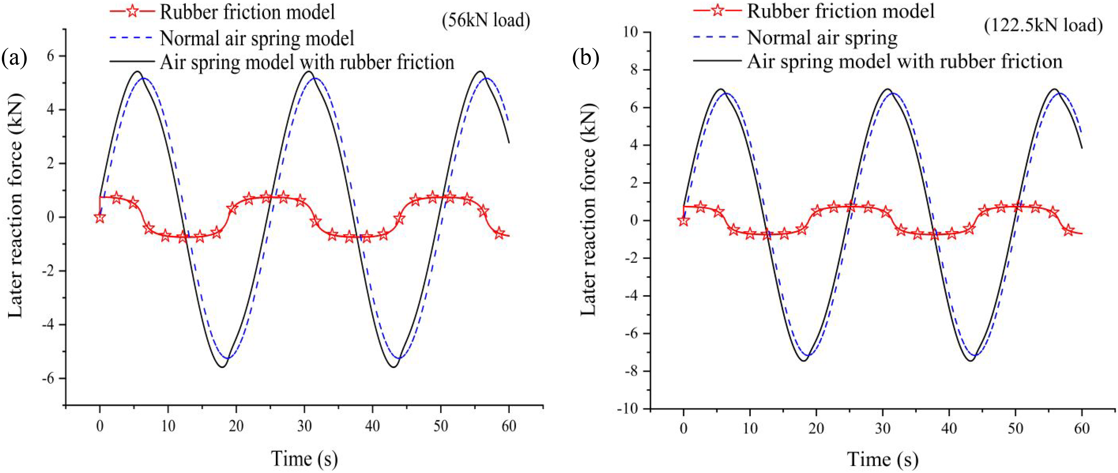
The simulated parameters are similar to the real data, reflecting the model’s vertical and lateral nonlinear characteristics. The simulation proves that the model can be used for subsequent research.
Research on the influence of orifice damping
For the bogies of EMUs or metro vehicles, there are generally two different configurations of secondary vertical damping: one is configured with a vertical damper, which is characterised by good performance but high cost, and the design is slightly complex. The second is the configuration orifice, characterised by constant damping, simple design, and cost-saving.
The running speed of metro vehicles is lower than that of EMUs, and the passenger capacity is ample. In order to study the influence of orifice damping on metro vehicles, the nonlinear critical speed, riding stability, and curve passing performance of three different diameter orifice and vertical dampers are compared. Track excitation is the American sixth track spectrum density. (When the vehicle damper is configured, the orifice is considered maximum, ignoring the influence of orifice damping).
Nonlinear critical velocity analysis
The nonlinear critical speed is a significant reference index for vehicle design, and its value should be greater than the design speed. The excitation is applied to just one line segment when the vehicle travels straight. It is defined as a nonlinear critical velocity when the wheel’s transverse motion is neither divergent nor convergent.
Figure 6 shows that the damping configuration has little impact on the critical speed and meets the actual vehicle speed requirements. The critical speed of the AW3 is more significant than the AW0 condition. The effect of damping configuration on the critical speed.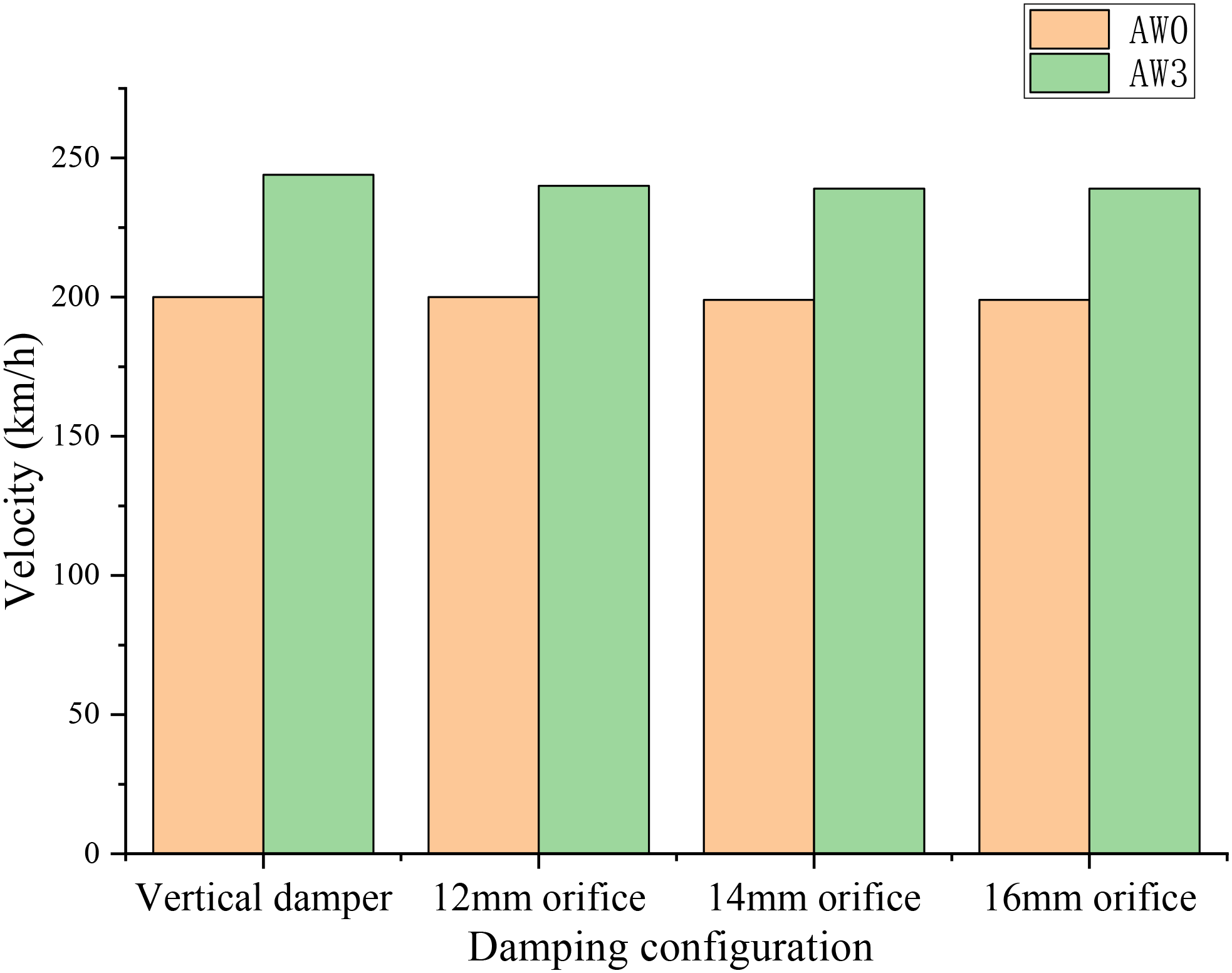
Analysis of straight-line running stability
Considering the design speed and operation conditions, metro vehicles’ acceleration and riding quality indexes are calculated, operating in a straight line between 40 km/h and 120 km/h under the AW0 working condition. The results obtained are maximised and, as shown in Figure 7. Impact of secondary vertical damping configuration on vehicle running stability (a) Lateral stability (b) Vertical stability(c) Lateral vibration acceleration of car body (d) Vertical vibration acceleration of car body.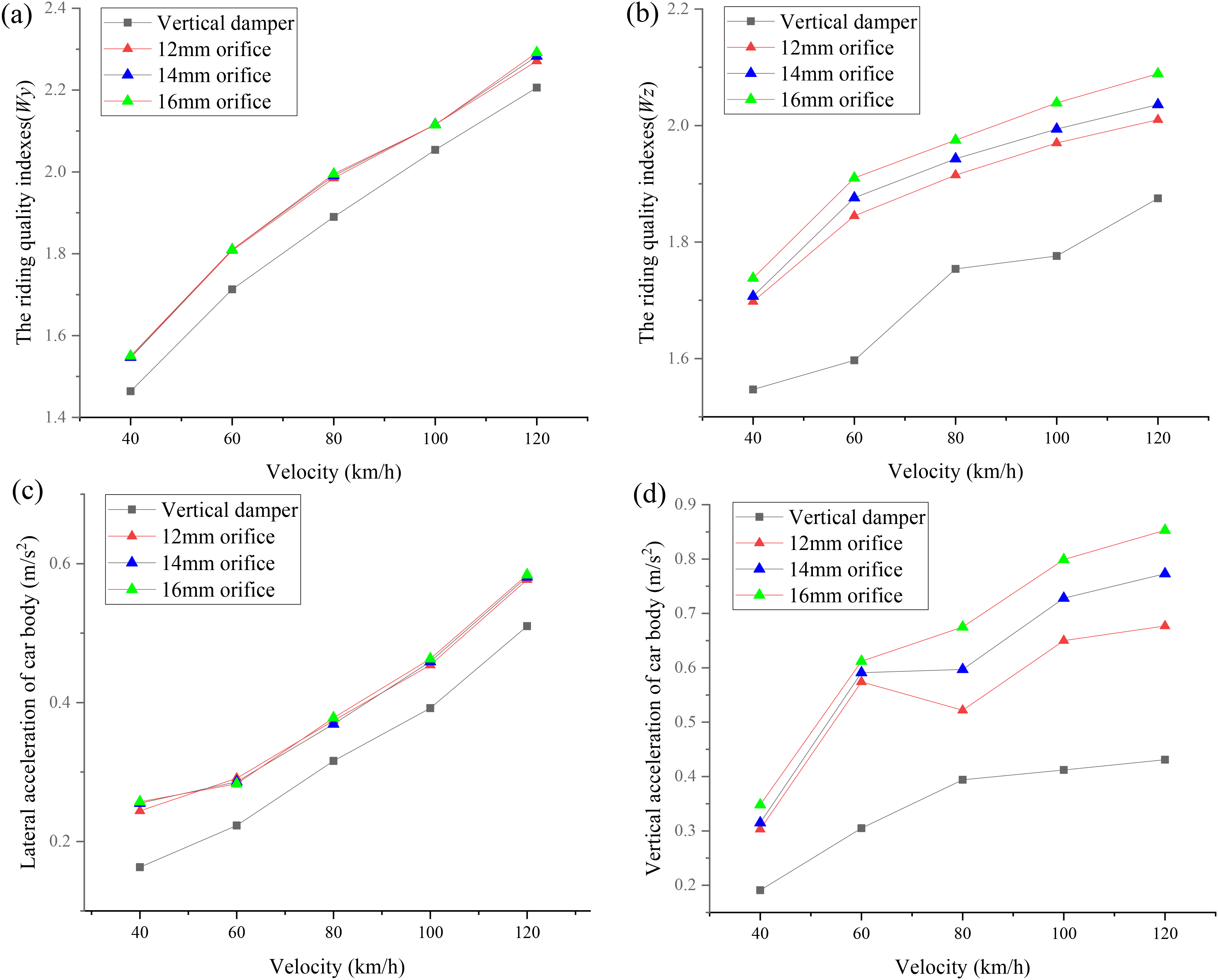
Figure 7 shows the vehicle dynamics performance is worse with the increased running speed. The vertical damping configuration dramatically influences the vertical stability and vertical acceleration, but it is not significant in the lateral. With the decrease in orifice diameter, the vehicle stability index and running quality index are better, and the vertical damper performance is the best. However, all the projects meet the requirements of GB/T 5599-2019 《Specification for dynamic performance assessment and testing verification of rolling stock》in China, 33 and the running stability reaches an excellent level. In sum, a 12 mm orifice damping configuration is the best.
Analysis of curving performance
Curve setting.
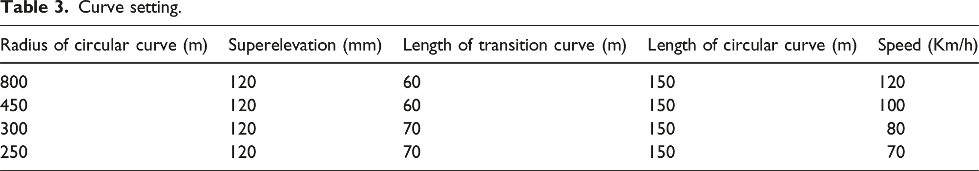
Figure 8 shows that under different curve conditions, the configuration of vertical damping has little effect on the derailment coefficient, wheel load reduction rate and wheelset lateral force of metro vehicles, and the operation stability can meet the requirements of GB/T 5599-2019. Considering the overall cost, it is sufficient to configure the orifice as the main vertical damping without needing the vertical damper. Influence of secondary vertical damping configuration on vehicle running safety (a) Derailment coefficient (b) Wheel load reduction rate (c) Wheelset lateral force.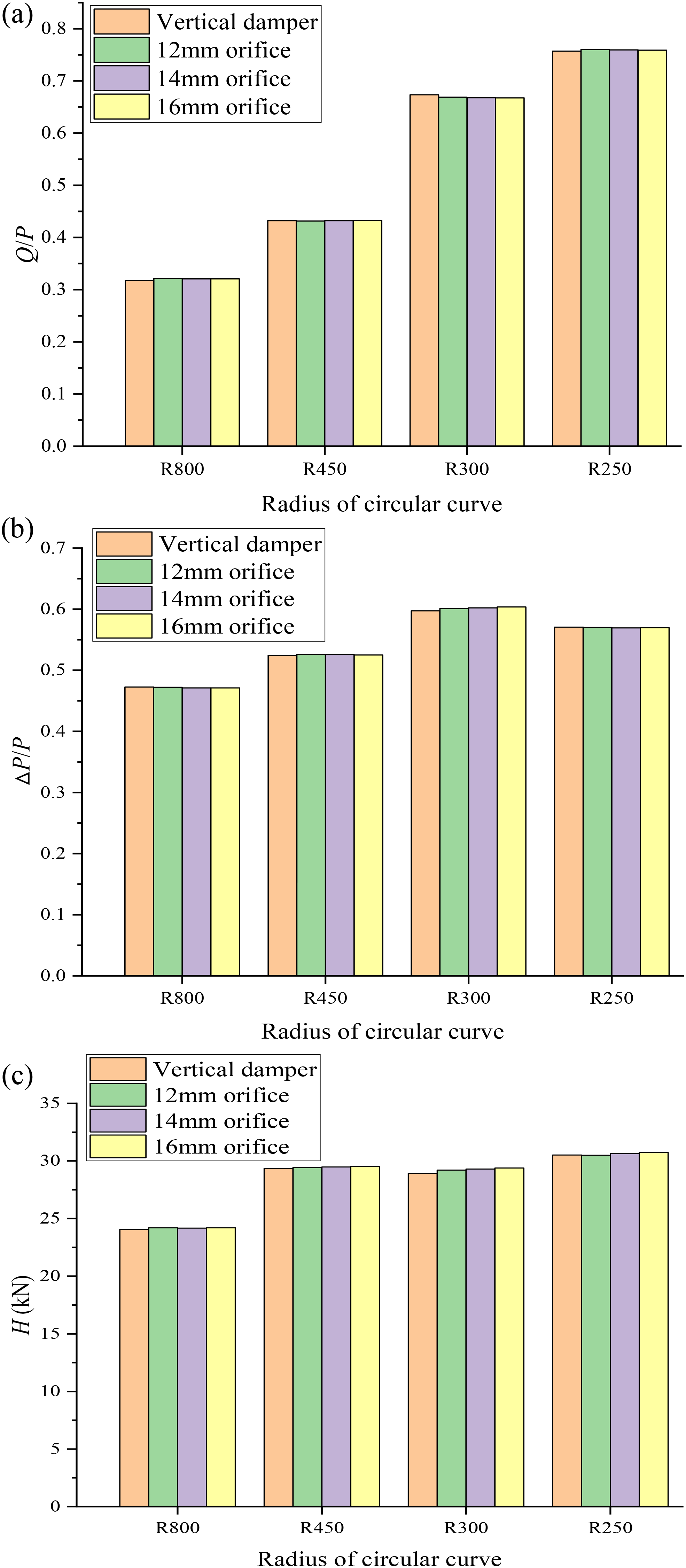
Conclusion
By establishing a complete three-dimensional air spring model, the influence of the orifice diameter and the secondary vertical damper on the dynamic performance of the metro vehicle is studied. The research results are as follows: (1) Through the simulation test, the accuracy of the nonlinear rolling lobe air spring model is verified, and it has excellent vertical and lateral nonlinear characteristics. (2) When analysing the damping characteristics of air suspension, it has less impact on the critical speed. It is much better than the design requirement, so the critical speed index can be ignored when analysed. (3) When the vertical damper is used in metro vehicles, its nonlinear critical speed and running stability index are better than the orifice, and the running stability is the same. The smaller the orifice diameter, the better the running stability of the vehicle. (4) There is no need to configure the secondary vertical damper of the metro vehicle. The air spring with a smaller diameter orifice is better, ensuring great dynamic capacity and reducing the cost, simplifying the design.
Footnotes
Declaration of conflicting interests
The author(s) declared no potential conflicts of interest with respect to the research, authorship, and/or publication of this article.
Funding
The author(s) disclosed receipt of the following financial support for the research, authorship, and/or publication of this article: This work was supported by the National Natural Science Foundation of China (51965016).