
Abstract
Pursuing electric mobility has led to a growing demand for efficient battery enclosures that can withstand dynamic forces and vibrations. This study focuses on advancing the structural integrity and vibrational resilience of battery enclosures through a holistic optimization approach. This research identifies optimal design parameters that minimize deformation and stress while maximizing resonance frequency by leveraging finite element analysis, modal analysis, and multi-objective optimization techniques. The study unveils three candidate designs that showcase remarkable improvements, including a 49.41% reduction in deformation, a 35.79% reduction in stress, and a 19.92% increase in resonance frequency. These findings underscore the potential of integrated design strategies to drive innovation in sustainable electric vehicle technologies.
Keywords
Introduction
In transitioning towards a sustainable future, the widespread adoption of electric vehicles (EVs) is a notable stride towards reducing emissions, enhancing efficiency, and embracing sustainable transportation solutions. 1 A pivotal facet of this transition is the utilization of lithium-ion batteries, which serve as the backbone of EV power supply. The paramount concern in this context is the overall efficiency of the power source and the holistic safety of the battery pack which is important for the reliability of EVs. 2 Recent research has aimed to comprehensively address the failures that cause lithium-ion battery accidents and formulate preventive strategies to avoid damages, even during battery failure. 3 This landscape of EVs and lithium-ion batteries has seen notable contributions to enhance their performance and safety. Advancements include using neural networks to estimate state of health (SOH) through parameters such as temperature and discharge rates.4,5 Also, the research on pack design 6 becomes important for safe operation by investigating diverse models to assess their thermal behavior and heat transfer which are critical factors in ensuring safe and efficient operations. 7 The spectrum of safety considerations is broad, encompassing concerns such as thermal runaway and internal short circuits (ISC). Wang et al. 8 have undertaken a comprehensive review that encompasses ISC formation, detection, and mitigation. Further insights have been inferred from studies like Xie and Yao’s assessment of the safety of 18650 cells under axial nail penetration conditions. 9
In the context of EV operation, the battery pack encounters vibrational forces from various sources like uneven road surfaces, changes in road gradients, and vibrations stemming from propulsion systems. 10 Recognizing the impact of these vibrations, comprehensive vibration testing emerges as a pivotal design element for battery packs. These tests subject the battery pack to frequencies exceeding 300 Hz. 11 Consequently, these forces engender deformations and stresses within the battery pack’s enclosure, underscoring the necessity for enclosure design to preclude failures that could compromise the vehicle’s safety. 12 A sturdy enclosure safeguards cells against physical damage, such as impacts and punctures, which might result in malfunctions and flames. By controlling heat loss, effective enclosures retain batteries running at safe temperatures and head off problems like thermal runaway. 13 They prevent short circuits by acting as an insulating barrier, and they protect the cells from things like moisture and contaminants that could otherwise lead to corrosion or weak performance. 14 Modern enclosures combine sensors to keep track of battery health and circumstances, ensuring rapid interventions and further mechanical support, preserving batteries in their designed configuration, especially under dynamic situations. They also provide room and ventilation for battery characteristics like swelling and gas release. 15 As a last line of defense against possible dangers, a well-designed battery enclosure significantly improves battery lifespan, protection, and performance. 16 Subsequent to a battery pack enclosure has been designed, a detailed examination must be performed to verify its reliability and performance under real-world conditions. This process ensures that no unsafe conditions, such as thermal runaway or short circuits, will arise. It enables improvements in managing heat and structural integrity, hence increasing the lifetime and reliability of the system. Finally, post-design analysis verifies that the enclosure meets all applicable norms and standards, provides guidance for making adjustments that minimize costs, and evaluates the enclosure’s flexibility in various operating contexts. The design is the blueprint, but the analysis ensures it will work as intended and is secure. 17
There are three main factors to consider when analyzing a battery enclosure: the structure, the temperature, and the vibration. The examination verifies the enclosure is structurally sound, protecting the inside cells and components from physical harm. To keep the battery working at its best and to minimize problems like thermal runaway, 18 where overheating may lead to fires or explosions, it guarantees efficient heat dissipation and temperature management. 19 For instances in which dynamic forces are steady, such as electric cars, vibration analysis is essential to study the battery’s reaction to oscillatory movements. 20 Vibration analysis, while important in all three dimensions, is particularly crucial. Vibration analysis protects the battery from unpredicted, dynamic forces that can cause accelerated wear, possible inconsistencies, or even internal damages, ensuring durability and uniform performance in varying operational conditions, in contrast to structural and thermal features, which primarily protect against static or steady-state hazards. 21
In evaluating the structural integrity and performance of battery pack enclosures, our research has employed Finite Element Analysis (FEA) as the primary tool. The choice of FEA is driven by its unparalleled ability to provide a comprehensive simulation of complex physical interactions such as thermal behavior, mechanical stress, and deformation under various loading conditions. This level of detail is crucial for ensuring the safety and reliability of battery enclosures, which are subject to rigorous operational demands and safety standards. While alternative methodologies such as SOBOL-based design of experiments, machine learning model training, and model creation with optimal model architecture with the least overfitting 22 and Bayesian optimization-based non-uniform sampling 23 are noted for their efficiency in high-dimensional design space exploration and are increasingly used in the development of surrogate models, these techniques often require further validation when applied to systems where physical interaction plays a critical role. Surrogate models, by nature, involve approximations that might not fully encapsulate essential dynamics specific to battery enclosures, such as precise load distributions and complex material behavior. 24 FEA, in contrast, offers direct solutions to the governing physical equations without relying on empirical assumptions, thereby enhancing the fidelity and accuracy of our analyses. 25 This approach is particularly indispensable given the stringent compliance requirements with safety regulations that our battery enclosure designs must meet. FEA enables the detailed assessment of specific failure modes and critical load cases that are imperative for certification and market approval. There are several defining moments along the course of our investigation. First, we describe the design of the case, with a focus on finding the most important factors to be optimized. The next step is to test potential materials for the housing through modal and structural evaluations under different environmental settings. Finally, we integrate certain output parameters into the housing via response surface optimization to guarantee the appropriate performance characteristics. To the authors’ knowledge, the present study is the first to report on the use of specifically tailored boundary conditions that accurately simulate the real-world operational stresses encountered by battery enclosures, including maximum deformation during braking, sharp turns, and vertical impacts. This approach marks a significant advancement in the field, providing a more comprehensive assessment of battery enclosure integrity and safety under actual driving conditions.
Designing of enclosure for battery pack safety and performance
The design of an enclosure for a battery pack is crucial for both safety and performance. An effective enclosure safeguards the battery cells from external impacts, and environmental factors such as moisture and temperature fluctuations, and mitigates risks associated with thermal runaway. Adequate ventilation or thermal management is essential to ensure batteries operate within their optimal temperature range, enhancing longevity and efficiency. Incorporating flame-retardant materials and fuses can prevent potential fires or explosions. The enclosure should also facilitate easy monitoring and maintenance of the battery pack while ensuring secure electrical connections and insulation. Proper design not only enhances battery lifespan and efficiency but also ensures the safety of users and the surrounding environment.
Structural design and material considerations
Enclosure configuration and component
Figure 1 portrays the structural blueprint of the enclosure, precisely configured to accommodate a battery pack composed of 300 18650 cells, a key element of modern electric vehicles. This pack configuration is further enhanced through the parallel integration of heat pipes for efficient cooling. Structural design of the enclosure.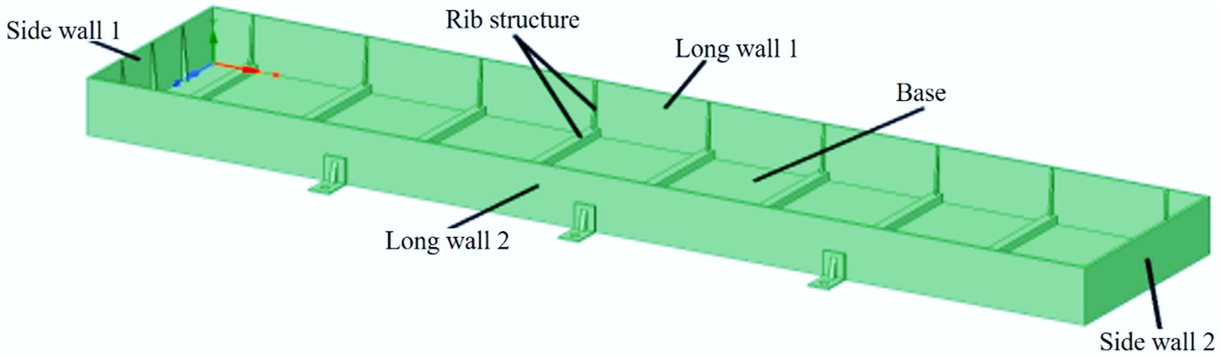
For ease of cell placement, a supportive plate (illustrated in Figure 2) is introduced, although its influence on the structural integrity of the casing remains negligible, thus deemed inessential for subsequent structural analyses. Design of base plate to hold cells.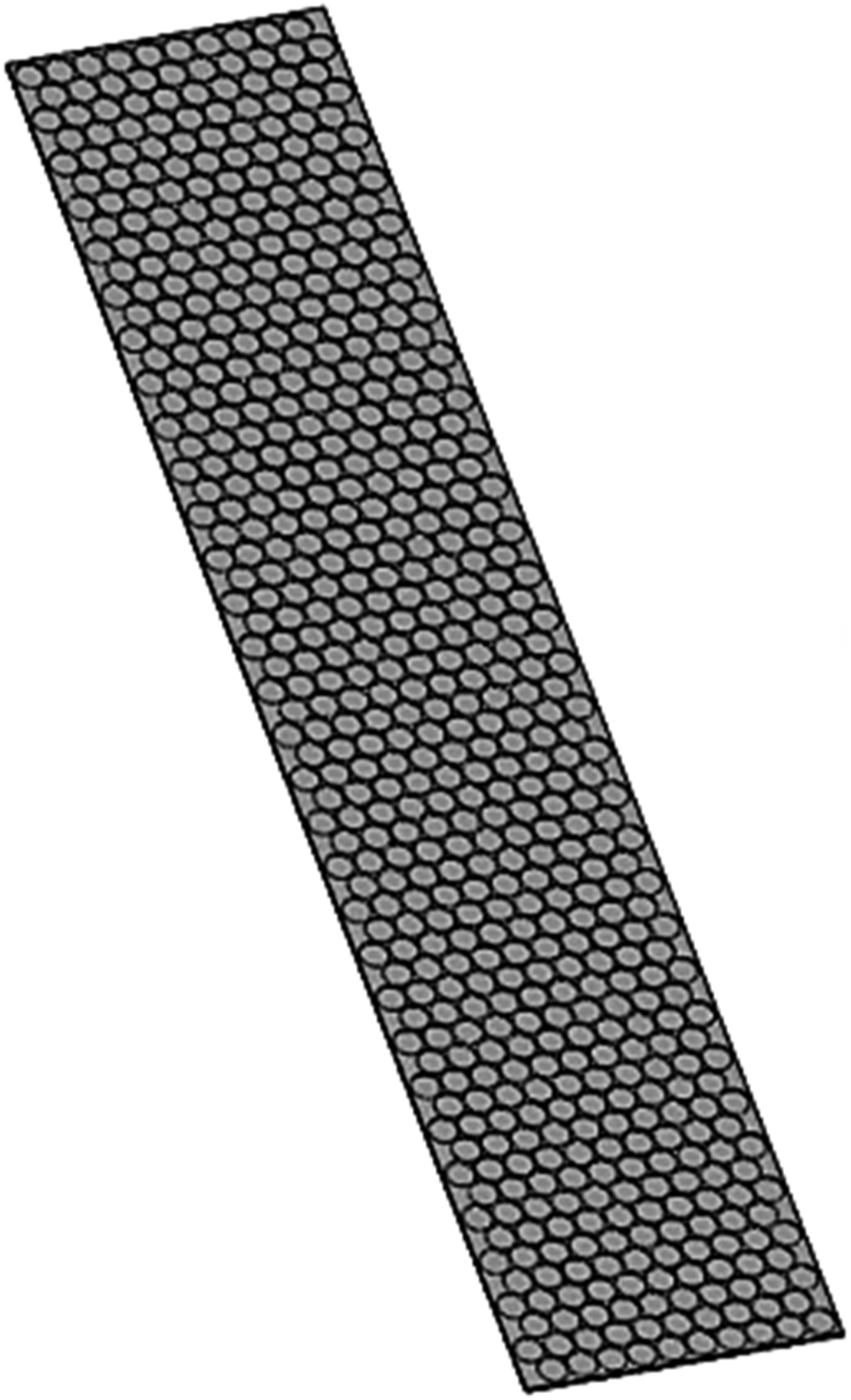
The design of this enclosure is executed using Space Claim software, with the strategic integration of ribbed structures to confer heightened structural rigidity. Divided into distinct components, the enclosure encompasses: (a) side walls (aligned with the box’s width), (b). long walls (extending along the box’s length), and (c) the base. Notably, six fastening positions are strategically incorporated—three on each side—to ensure secure assembly.
Materials
Material properties.
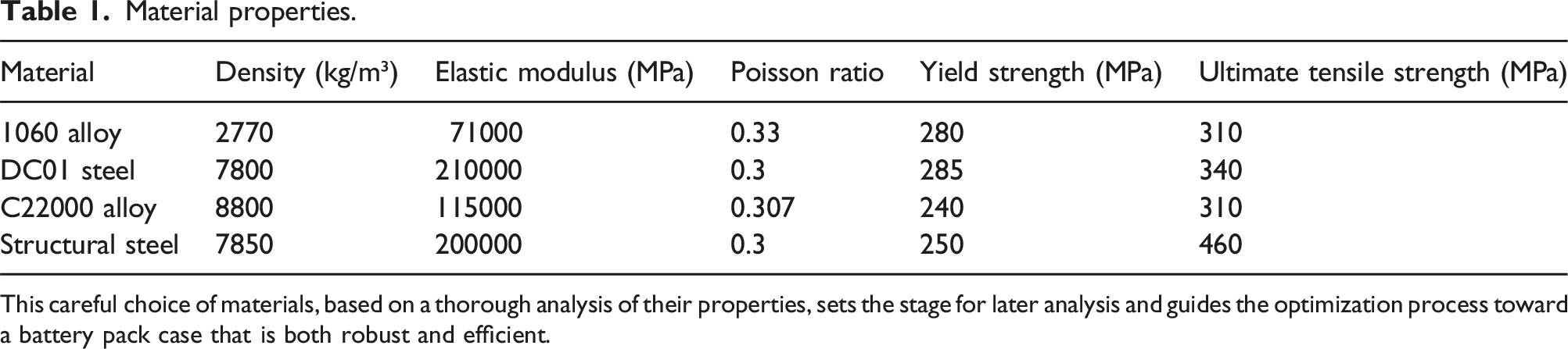
This careful choice of materials, based on a thorough analysis of their properties, sets the stage for later analysis and guides the optimization process toward a battery pack case that is both robust and efficient.
Dynamics unveiled: Modal analysis of battery enclosure
Within the complex and interconnected system of pressures and frequencies that shape the operational environment of battery enclosures, it is crucial to prioritize the structural robustness. The enclosure can experience resonance when external frequencies align with its inherent frequency, due to dynamic vibrations from various sources. Under resonance conditions, the vibrational elements attain maximal displacement, precipitating deformation or, worse yet, structural failure. 31
First six modal frequencies.
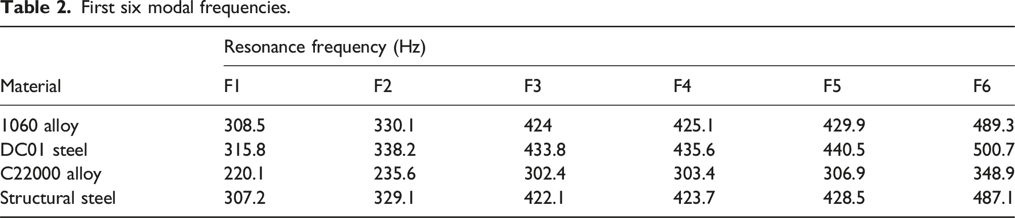
The outcomes of this analysis illuminate the resonance frequencies of the materials, offering insights into their susceptibility to resonance-induced deformation. Notably, both DC01 steel and 1060 alloy exhibit the highest resonance frequencies among the candidate materials. This can be attributed to their superior stiffness, as indicated by their higher Young’s Modulus values compared to the other candidate materials. Additionally, these materials may have favorable density characteristics, which contribute to their increased resonance frequencies. Their ability to efficiently distribute mass and possibly exhibit better-damping properties may also play a role.
33
While Figure 3 visually depicts the modal analysis specific to the 1060 alloy material, these findings underscore the materials’ pivotal role in mitigating the risk of resonance-related structural challenges. Modal analysis of 1060 alloy material.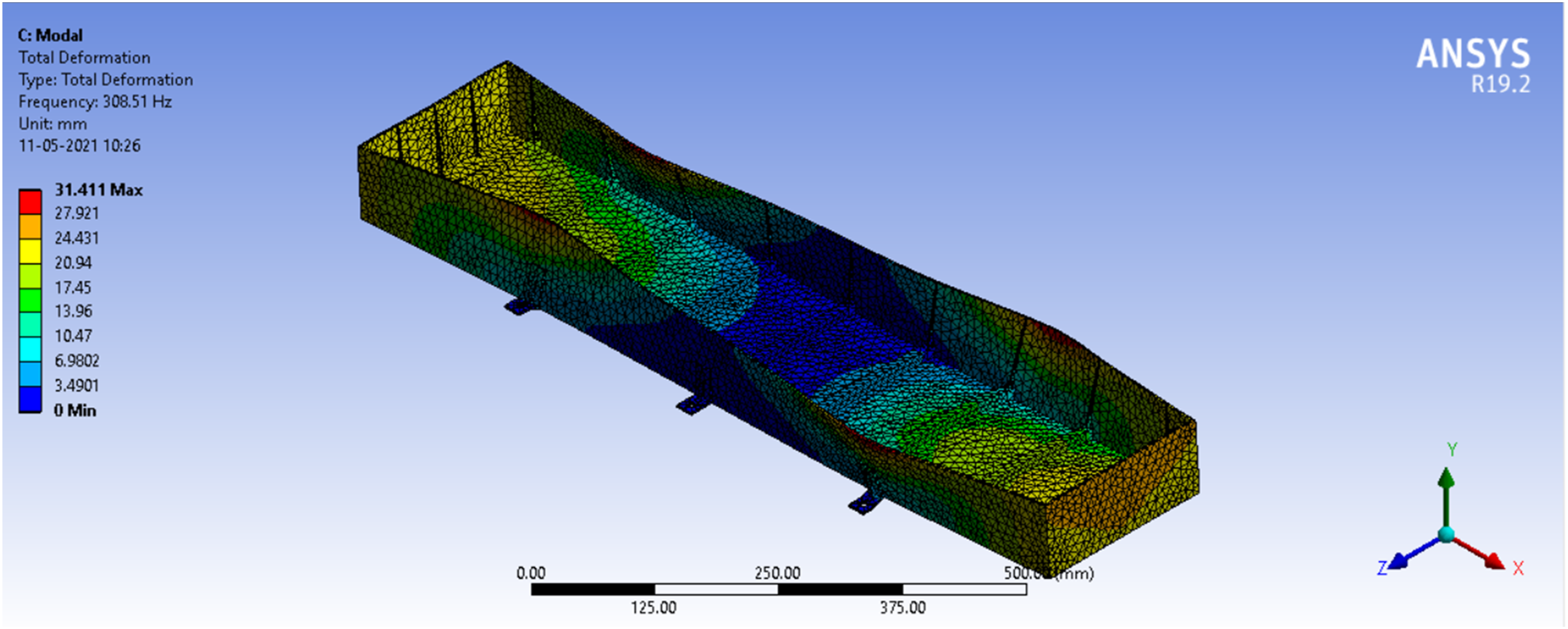
This dynamic analysis is a crucial aspect in assuring the strength and durability of battery enclosures. It combines the principles of material science with precise engineering techniques to get optimal results.
Strengthening structural integrity: static analysis of battery enclosure
As the electric vehicle takes to the road, it becomes a canvas for many static forces and accelerations intrinsic to real-time operation. The battery pack’s resilience in these dynamic challenges is a cornerstone in ensuring both vehicular safety and operational longevity.
34
Thus, this section delves into the static analysis undertaken to ascertain the enclosure’s ability to withstand a spectrum of conditions, each associated with distinct forces and accelerations. The dynamic repertoire of static forces and accelerations encompasses: a. Vertical Impact b. Sideways Turning c. Sudden Braking
Structural response.
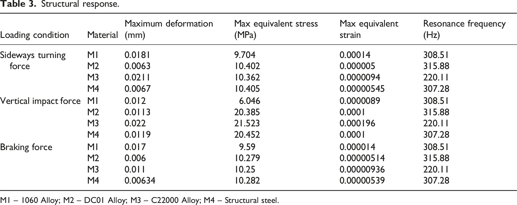
M1 – 1060 Alloy; M2 – DC01 Alloy; M3 – C22000 Alloy; M4 – Structural steel.
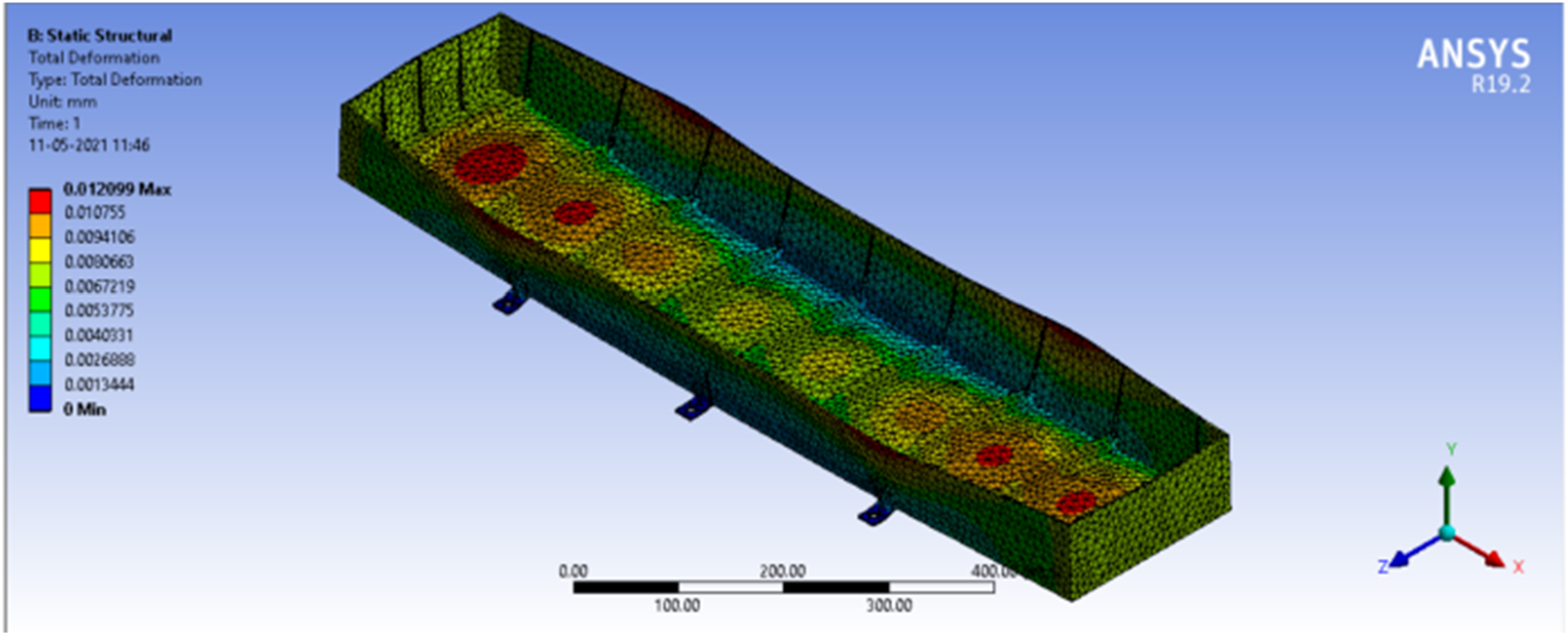
The analysis of structural responses to various forces (sideways turning, vertical impact, and braking) reveals that DC01 Steel consistently exhibits the lowest maximum deformation across all scenarios, while 1060 Alloy has the lowest maximum equivalent stress and strain values. Both DC01 Steel and 1060 Alloy maintain a consistent resonance frequency of approximately 315.88 Hz and 308.51 Hz, respectively, indicating their vibration resistance. DC01 Steel demonstrates the best overall performance, with the lowest deformation, relatively low equivalent stress and strain values, and a consistent resonance frequency, making it a suitable choice for the EV battery enclosure. This superior performance can be attributed to its high Young’s Modulus and favorable material properties, providing greater stiffness and structural integrity under different forces. 35 This stiffness helps minimize deformation and stress, ensuring the enclosure’s structural stability.
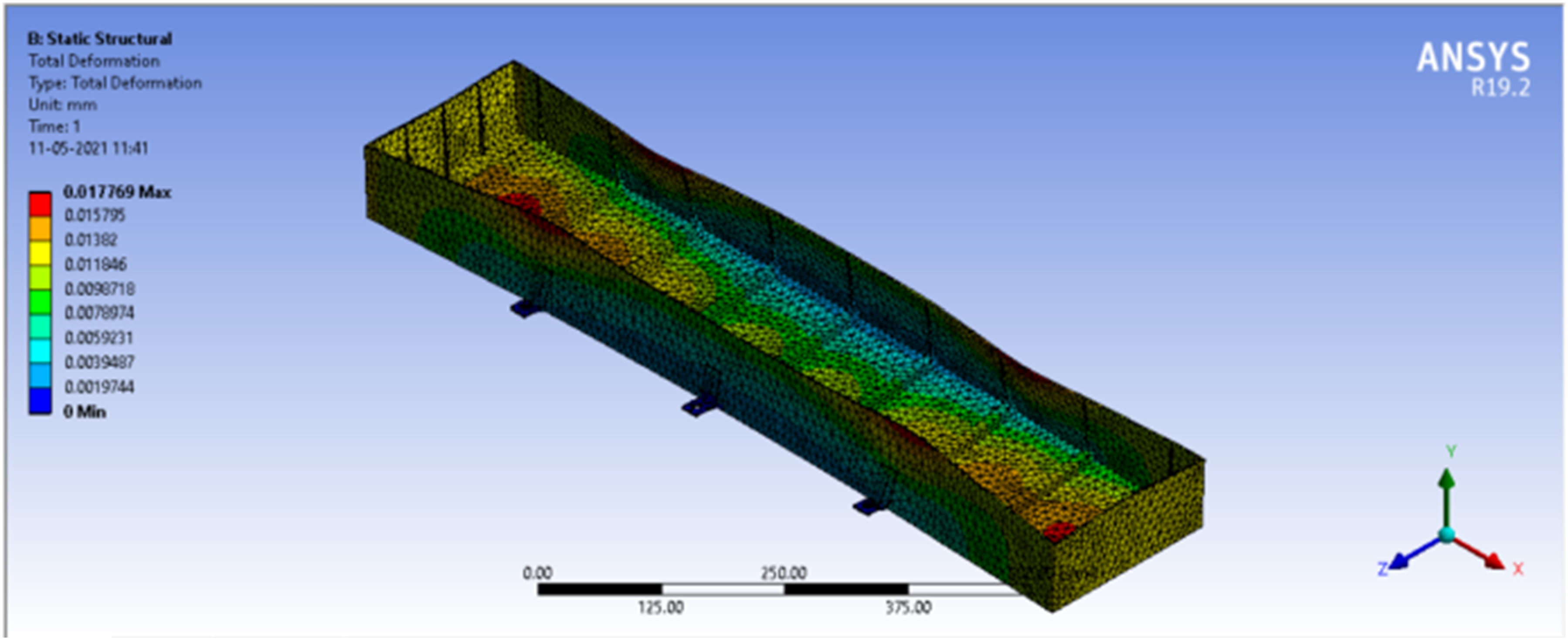
Visualizations further enrich these findings, with Figures 4–6 revealing the maximum deformations under different force scenarios—braking, sideways turning, and vertical impact, respectively. These figures offer a tangible glimpse into the enclosure’s dynamic response, affirming its structural resilience across diverse operational conditions. Max Deformation in braking. Max deformation while turning sideways. Max deformation in vertical impact.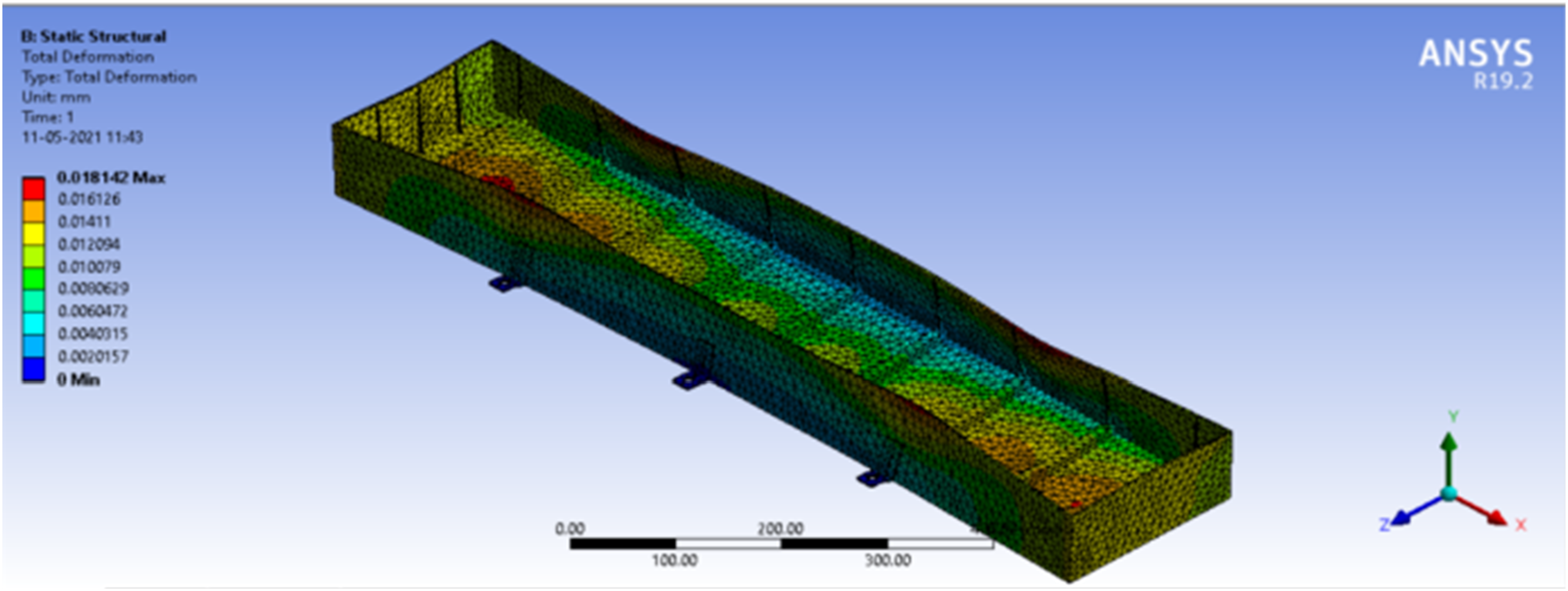
Precision-driven optimization: Exploring design parameters
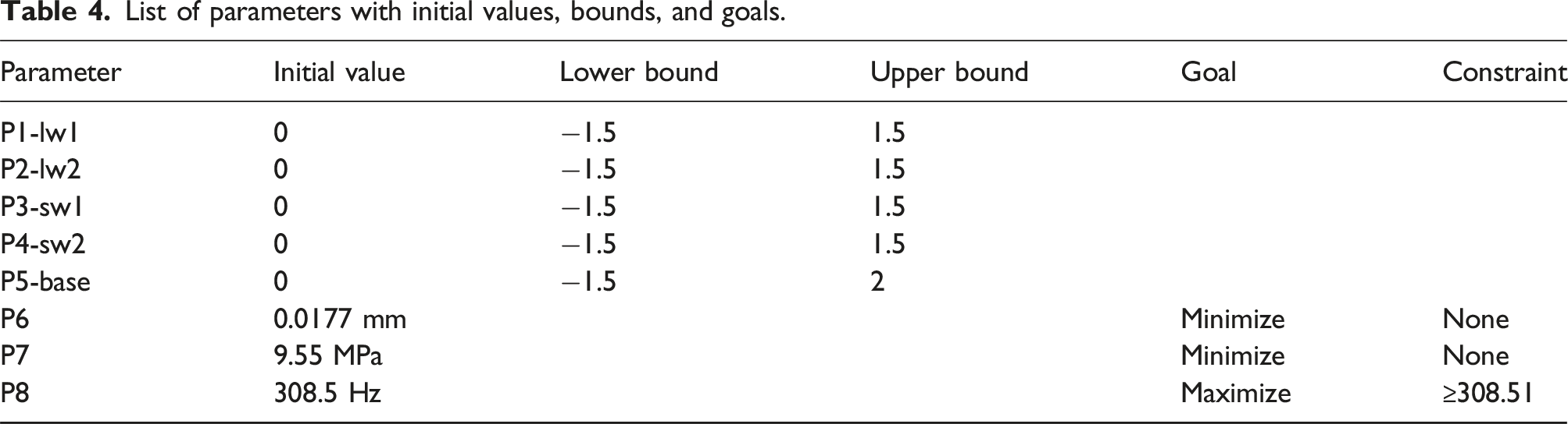
This section explores the role of the thicknesses of the enclosure’s side walls, long walls, and base parameters in enhancing the structural integrity and performance of the enclosure. As the initial step, a uniform thickness of 3 mm was adopted for these structural elements. However, the exploration was far from over. The parameters under study are P1-lw1 (long wall 1), P2-lw2 (long wall 2), P3-sw1 (side wall 1), P4-sw2 (side wall 2), and P5-base were granted varied thicknesses within specific limits. As depicted in Table 4, the parameter bounds underwent a comprehensive exploration encompassing positive and negative alterations from the initial 3 mm. Optimization pursuits rested upon a triad of essential factors, namely: • P6 Max. Total Deformation: Minimize • P7 Max. Equivalent Stress: Minimize • P8 Frequency at Total Deformation: Maximize (with a constraint of ≥308.51 Hz) List of parameters with initial values, bounds, and goals.
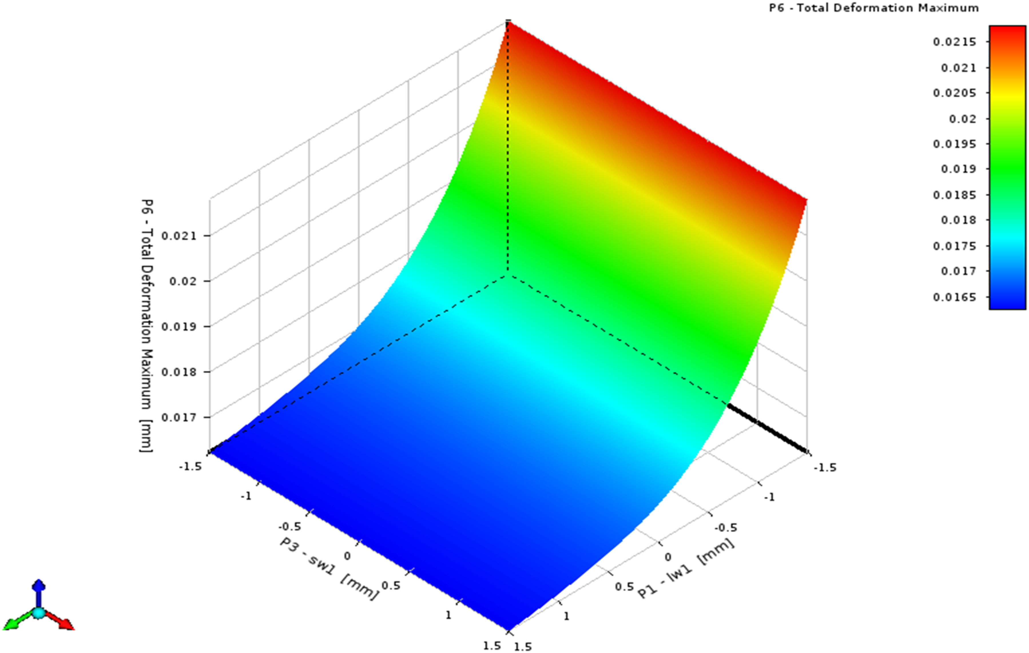
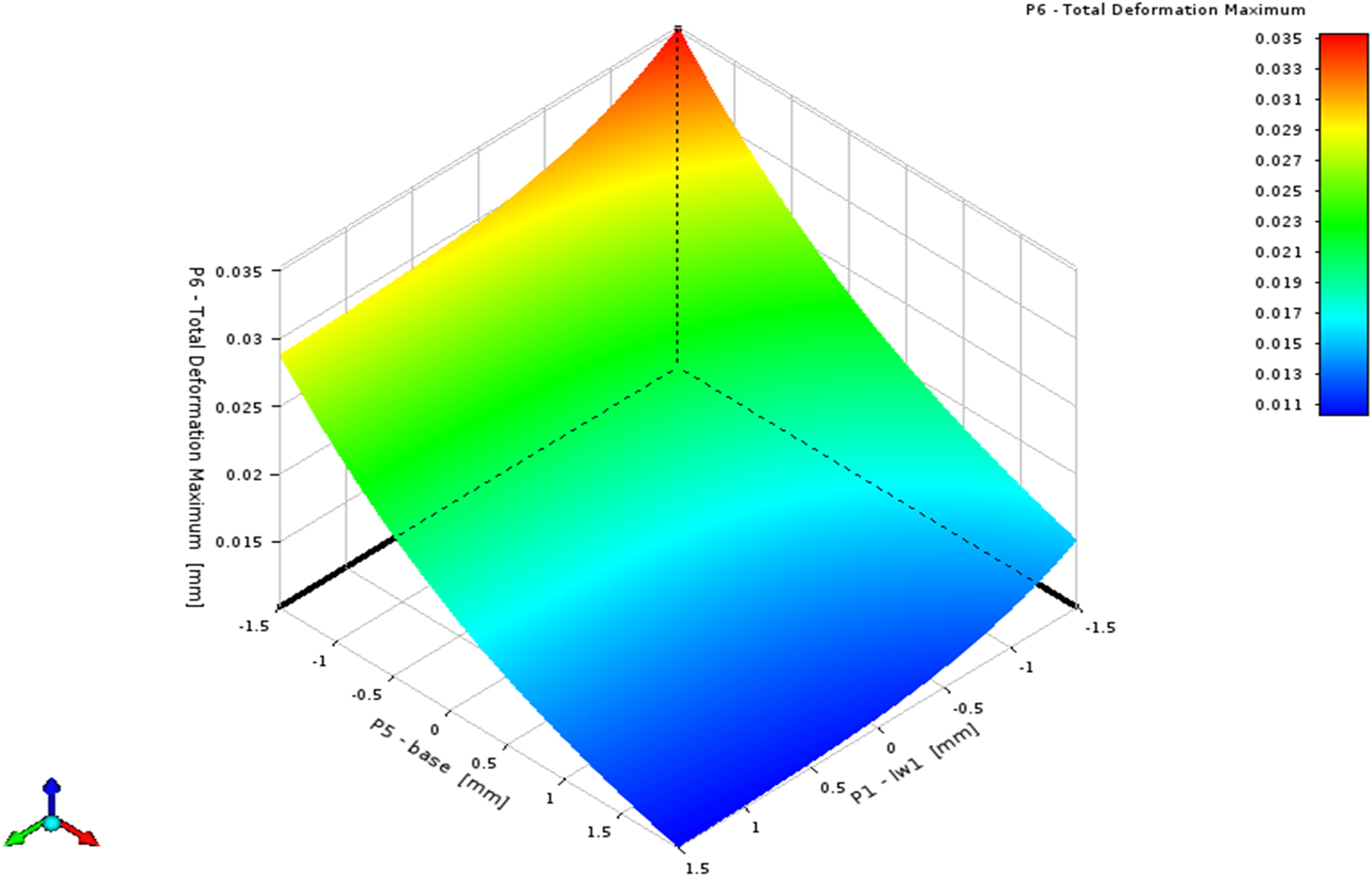
The multi-objective Global Optimization technique (MOGA), a variant of the NSGA-II algorithm, coupled with the standard response surface methodology, orchestrated the exploration of 95 design points across the parameter space. The aim was to identify configurations that seamlessly amalgamate structural integrity and performance prowess. MOGA was employed since it offers a flexible and robust approach to finding a diverse set of solutions, especially beneficial for complex problems where traditional methods might struggle to find multiple good solutions or handle the non-linearity and multimodality of the objective space. Figures 7–9 encapsulate the response surfaces that underscore the intricate relationships between the parameters and the P6 Max. total deformation output. These visualizations offer a glimpse into the dynamic landscape of design possibilities, with each contour revealing the complex interplay of parameter alterations. Illuminating the 3D response surface of total deformation versus P1 and P2. Navigating the 3D response surface of total deformation versus P1 and P3. Unveiling the 3D response surface of total deformation versus P1 and P5.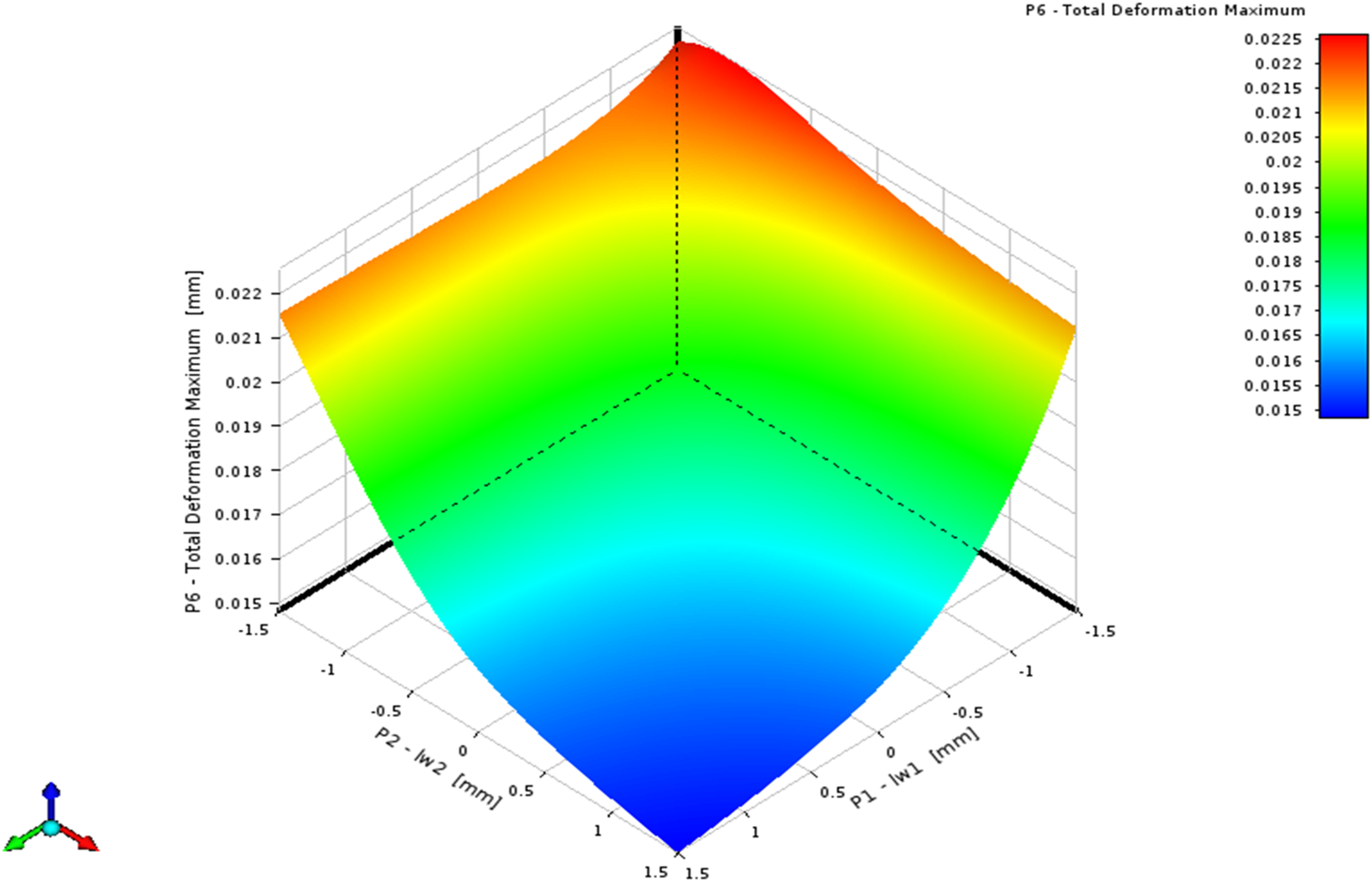
Visualizing the list of promising candidate points.
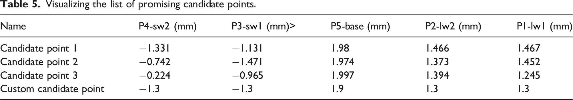
The optimization process aimed to strike a delicate balance between structural integrity and performance optimization. The chosen parameters’ bounds allowed for both positive and negative alterations from the initial 3 mm thickness, enabling a comprehensive exploration of the parameter space. By minimizing deformation and stress while maximizing resonance frequency, these candidate points were identified as they represent configurations that offer enhanced structural resilience and performance. The selected configurations provide a unique equilibrium that enhances the structural integrity of the enclosure, minimizing deformation and stress under various loads, while also optimizing performance by maximizing resonance frequency. Implementing these configurations in the actual battery enclosure design has the potential to enhance the safety, durability, and overall performance of the electric vehicle.
ANOVA analysis
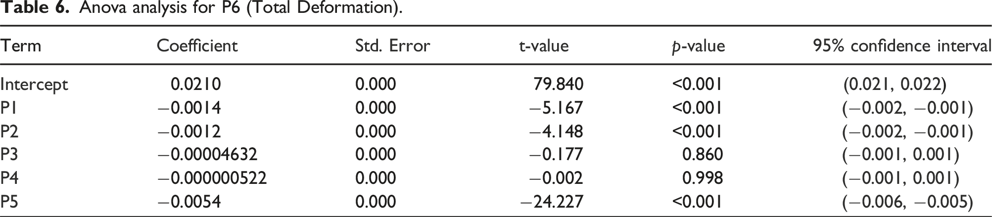
Anova analysis for P6 (Total Deformation).
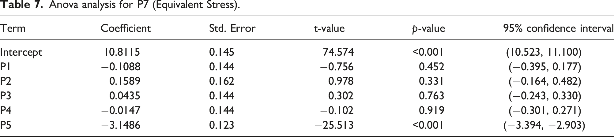
Anova analysis for P7 (Equivalent Stress).
Anova analysis for P8 (Deformation Frequency).
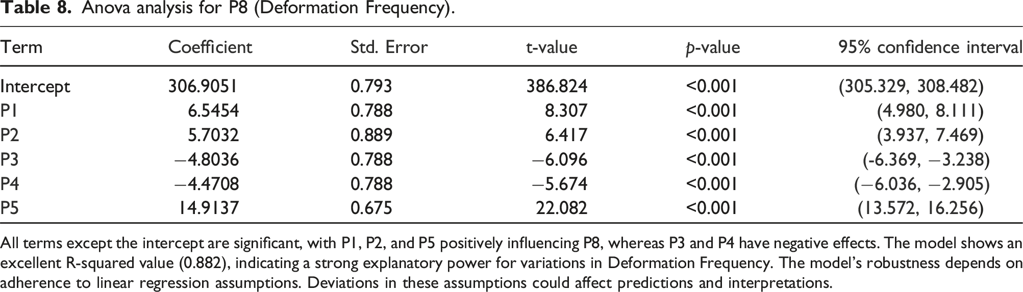
All terms except the intercept are significant, with P1, P2, and P5 positively influencing P8, whereas P3 and P4 have negative effects. The model shows an excellent R-squared value (0.882), indicating a strong explanatory power for variations in Deformation Frequency. The model’s robustness depends on adherence to linear regression assumptions. Deviations in these assumptions could affect predictions and interpretations.
P6 = 0.02103 + −0.00135
P1, P2, and P5 show significant negative relationships with P6. Each unit increase in these predictors leads to a decrease in Total Deformation. Notably, P5 has the largest impact. P3 and P4 are not statistically significant, with p-values much higher than 0.05, indicating that changes in these parameters do not significantly impact P6. High R-squared (0.876) indicates that the model explains a large portion of the variability in Total Deformation. The adjusted R-squared (0.869) is also high, confirming a good fit with the number of predictors accounted for. The model assumes linear relationships and normal distribution of errors. Non-linearity or non-normal errors could affect the model’s accuracy. The regression equation (ii) used for determining the equivalent stress is as follows:
P7 = 10.81148 + −0.10883
P5 is the only statistically significant predictor showing a substantial negative impact on P7. P1, P2, P3, and P4 do not significantly influence P7, as suggested by their high p-values. Similar to P6, the model has high R-squared values (0.880), indicating excellent model performance in terms of explaining variability in the dependent variable. Assumptions about linearity and error normality are critical. If assumptions are violated, results might be biased or misleading. The regression equation (iii) used for determining the frequency at total deformation is as follows:
P8 = 306.90511 + +6.54545
Pareto front analysis
A three-dimensional Pareto plot to visualize the trade-offs among the multiple objectives of our optimization problem is presented in Figure 10. The objective is to minimize the critical parameters including stress, deformation, and frequency, with a particular emphasis on reducing any frequencies exceeding 308.51 Hz. The selection of three specific points on the Pareto front was guided by the objective to not only stay below these defined thresholds but also to balance the inherent trade-offs efficiently. These points represent scenarios where the reduction in one parameter does not adversely affect the others beyond acceptable limits, thereby providing optimal solutions in terms of structural integrity and operational efficiency. This choice was upon detailed computational modeling and simulation, ensuring that each selected point meets our stringent criteria for minimizing operational risks and enhancing performance within the specified constraints. The plot features three axes, each representing the normalized values of the output parameters P6, P7, and P8. Solutions from the dataset are depicted as blue scatter points, where each point’s position along the x, y, and z axes corresponds to the respective normalized values of P6, P7, and P8. The red points on this plot define the Pareto front, indicating a set of non-dominated solutions. These are considered optimal as any improvement in one objective necessarily results in the deterioration of at least one other objective. Additionally, the ideal solution, marked by a green point and located nearest to the origin, exemplifies the best compromise among the objectives, providing a target for achievable optimization. Pareto Plot visualizing trade-offs among optimization objectives.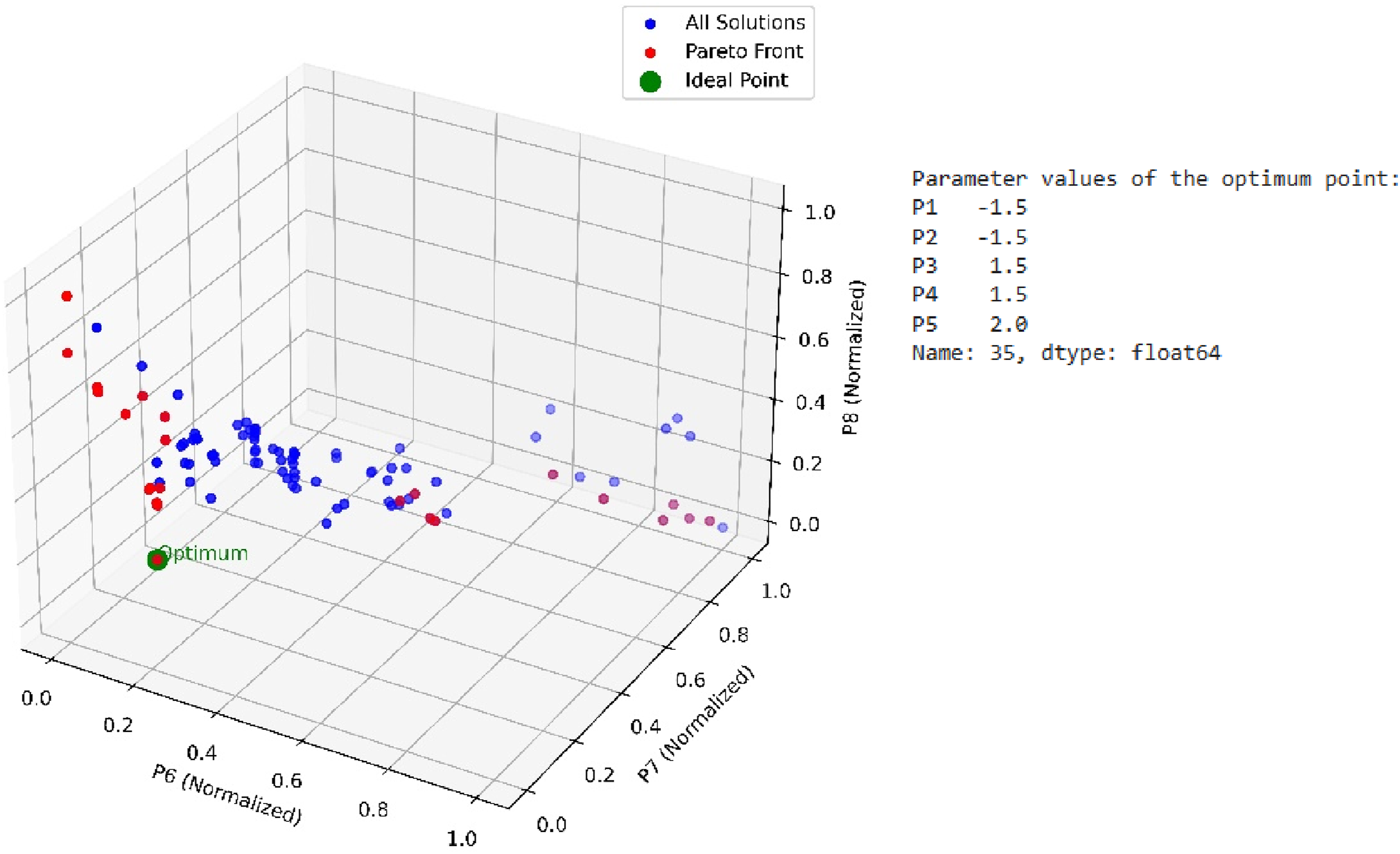
The optimum solutions, marked up within the plot, reveal the parameter configurations that achieve the most favorable balance between competing objectives. This visual and analytical representation aids significantly in understanding the complex interplay between multiple objectives and supports decision-making in fields requiring thorough optimization strategies, such as engineering and operational research.
The study is further intended to extend its phase towards to perform the Pareto characterization to derive optimal operator rules from the Pareto front solutions, upon a detailed investigation into the decision variables and a comprehensive exploration of how these variables interact under varying operational conditions.
Results and disclosure
A customized candidate point proximate to the suggested candidates was introduced strategically to streamline geometry creation. The transformation from the original values to these new settings is summarized in Table S1. While the initial design demonstrated commendable performance against static forces, an implicit assumption ensued that its attributes would only be further enhanced post-optimization.
A significant 49.41% decrease in total deformation was observed, indicating the newly found structural resilience. This can be attributed to the optimized configuration of the enclosure’s component thicknesses, which enhances its structural rigidity and minimizes deformation under various forces. 36 The equivalent stress, embodying the enclosure’s resilience, diminished by 35.79%, substantiating its enhanced fortitude. Furthermore, the remarkable 19.92% increase in resonance frequency underscores the superior vibrational performance achieved through the optimization process, affirming the enclosure’s ability to withstand external vibrations and ensuring its overall structural integrity and performance. Additionally, the optimization revealed an overarching consequence, trimming the weight by 38.59%, striding towards the holistic goal of vehicular efficiency and sustainability.
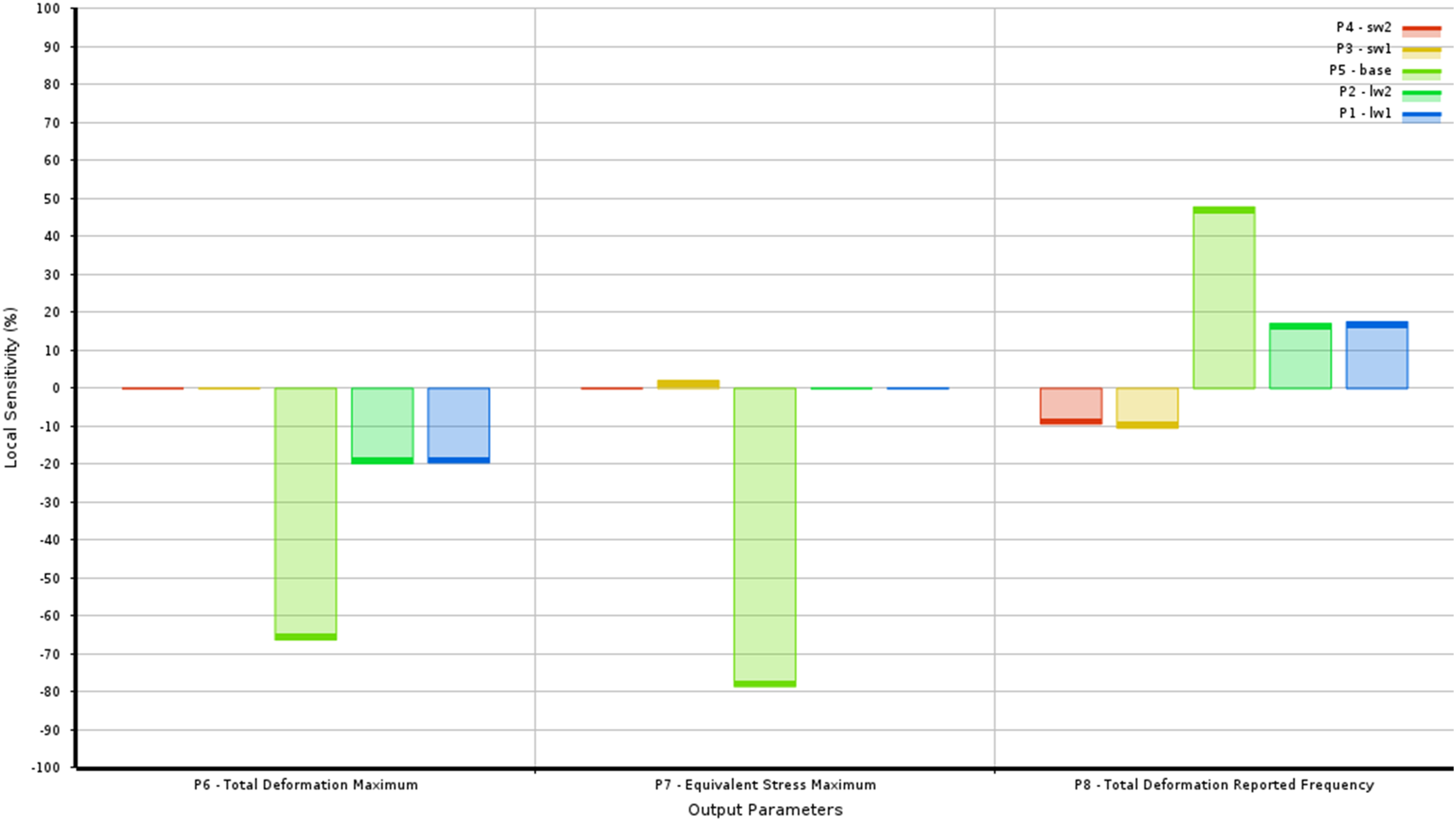
Analyzing the sensitivity of these achievements revealed valuable insights into the underlying processes. Among the design parameters, the thickness of the base of the EV battery enclosure emerges as the critical factor with the most profound impact on deformation attenuation primarily because the base serves as the foundation and primary load-bearing component of the enclosure.
37
Thicker base material provides greater resistance to deformation and better distributes the load, effectively minimizing deformation under various forces such as impact, braking, and lateral loads.
38
Comprising the core component in regulating and diminishing deformation, it guarantees the structural soundness and security of the battery system as the lower portion of the enclosure serves a critical function by providing support for the entire structure Figures 11 and 12. Intricacies of fit and form: Unveiling goodness of fit. The compass of influence: Navigating local sensitivity across parameters.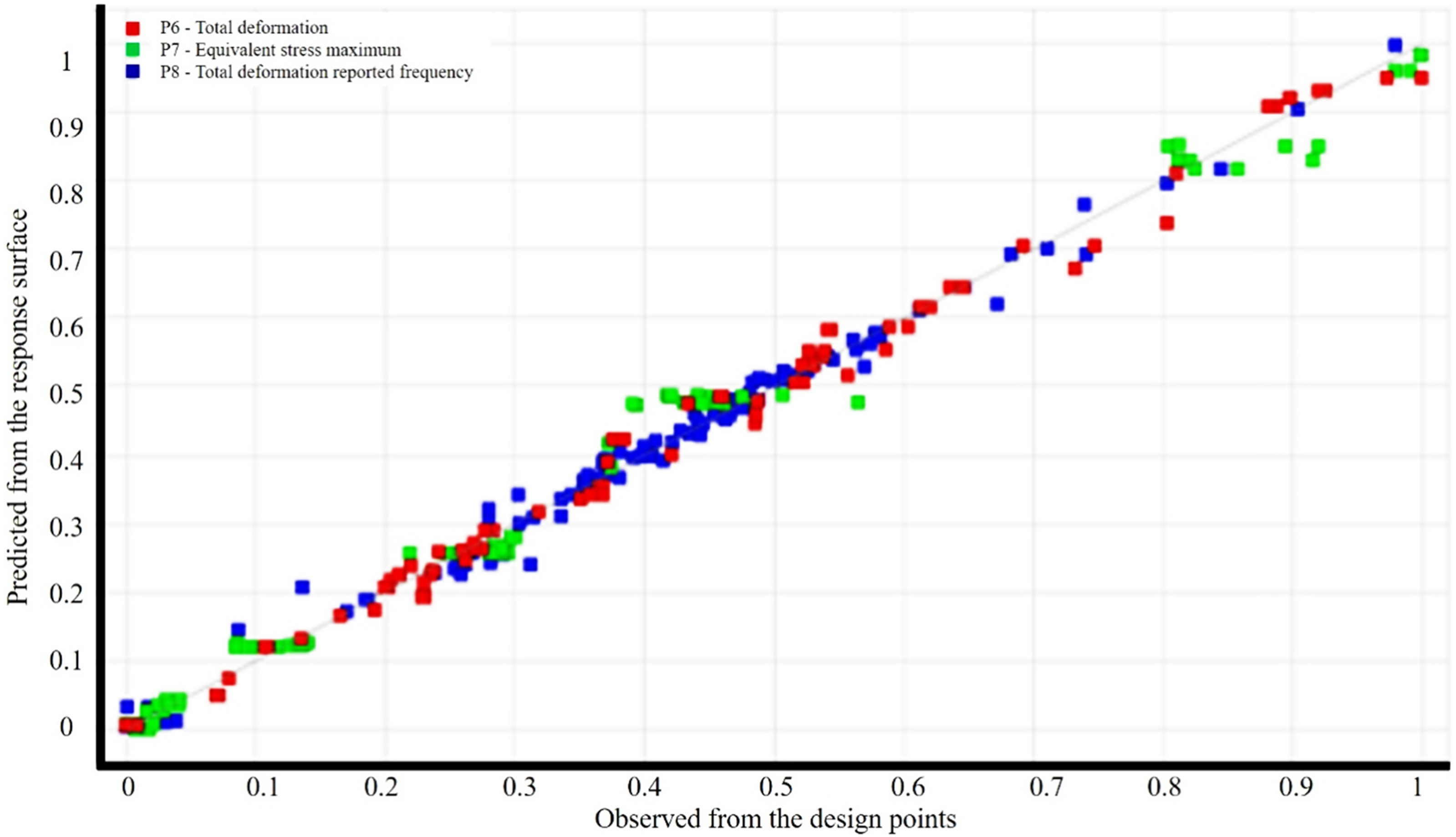
Comparison of initial design and optimal design.
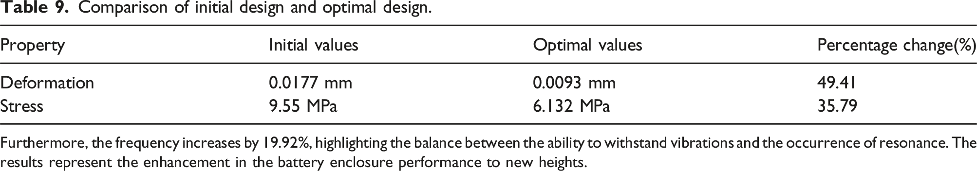
Furthermore, the frequency increases by 19.92%, highlighting the balance between the ability to withstand vibrations and the occurrence of resonance. The results represent the enhancement in the battery enclosure performance to new heights.
Conclusion
A comprehensive approach to enhance the structural integrity and vibrational resilience of battery enclosures for electric vehicles was performed. Findings demonstrate the significant impact of integrated design optimization on the performance of these critical components.
The optimization process led to a substantial 49.41% reduction in deformation, showcasing the enhanced structural robustness of the optimized designs. Concurrently, there was a notable 35.79% decrease in stress, signifying improved load-bearing capabilities. Furthermore, the resonance frequency substantially increased by 19.92%, indicative of heightened vibrational resilience. The numerical representations verify the efficiency of our approach and emphasize the potential for novel design strategy. The findings contribute to the advancement of electric vehicle technology and align with the predominant objective of development a greener and more sustainable transportation ecosystem.
Supplemental Material
Supplemental Material - Advancing structural efficacy and resonance performance of battery enclosures through multi-objective optimization
Supplemental Material for Advancing structural efficacy and resonance performance of battery enclosures through multi-objective optimization by G Naresh, T Praveenkumar, Dinesh Kumar Madheswaran, Jenoris Muthiya Solomon, Shivakumar Goud Kureli, Yash Kiran Kolhe, and Isaac Joshua Ramesh Lalvani J in Journal of Low Frequency Noise, Vibration and Active Control
Footnotes
Authors contributions
All authors were equally involved in the manuscript’s concept, design, and writing.
Declaration of conflicting interests
The author(s) declared no potential conflicts of interest with respect to the research, authorship, and/or publication of this article.
Funding
The author(s) received no financial support for the research, authorship, and/or publication of this article.
Consent to participate
On behalf of all authors, I, the corresponding author consent to participate in the research project, and the following has been explained to me: the research may not directly benefit me, but my participation is entirely voluntary.
Consent to publish
I, the corresponding author, give my consent for the publication of identifiable details, which can include a photograph(s) and videos and/or case history and/or details within the text (“Material”) to be published in the above Journal and Article.
Data availability statement
The datasets generated during and analyzed during the current study are available from the corresponding author upon reasonable request.
Supplemental Material
Supplemental material for this article is available online.
References
Supplementary Material
Please find the following supplemental material available below.
For Open Access articles published under a Creative Commons License, all supplemental material carries the same license as the article it is associated with.
For non-Open Access articles published, all supplemental material carries a non-exclusive license, and permission requests for re-use of supplemental material or any part of supplemental material shall be sent directly to the copyright owner as specified in the copyright notice associated with the article.