
Abstract
A computational model is proposed for the calculation of thermal deformation in ring gear, and the ANSYS Workbench platform is utilized to simulate the steady-state temperature field and thermal deformation in a planetary gear system. The simulation results are utilized to validate the accuracy of the ring gear thermal deformation calculation model. Furthermore, based on the data obtained from the steady-state temperature field, this research investigates variations in gear backlash and coupling stiffness within planetary gear systems caused by thermal deformation under variable speed and torque conditions. Additionally, a nonlinear dynamic model incorporating thermal deformation factors is established for a planetary gear system. By employing the 4-5 order Runge-Kutta numerical method, bifurcation diagrams and Largest Lyapunov exponents of the system under different operating conditions are obtained. Combining Poincaré maps, phase diagram, and spectral diagrams, an analysis is conducted on tooth impact states as well as nonlinear dynamic characteristics of the system influenced by thermal deformation.
Introduction
In high-speed and overloaded conditions, the elevated temperature resulting from friction between meshing tooth surfaces can lead to thermal deformation of gears. This thermal deformation significantly impacts the vibration, noise, and transmission accuracy of the system. In severe cases, it can even cause gear jamming and other failures that compromise operational safety and reliability. Therefore, in order to comprehensively analyze the nonlinear characteristics of the system and provide a theoretical basis for vibration reduction and noise control, it is imperative to investigate the nonlinear dynamic characteristics of the system under thermal deformation effects. Currently, there are two primary research methods employed for studying gear thermal deformation: analytical method and finite element simulation method. Li et al.1,2 proposed a theoretical calculation model based on thermal expansion theory and heat conduction differential equations to analyze the thermal deformation of external involute gears under temperature effects. Luo et al. 3 using an external meshing single-tooth finite element simulation model developed with Ansys APDL language, examined distribution patterns of tooth surface temperature as well as thermal deformations on gear surfaces. Chen et al. 4 also utilizing APDL language, analyzed radial distribution patterns of thermal deformations on gears through steady-state temperature field analysis. Tian et al. 5 through finite element modeling, investigated both steady-state temperature fields and thermal deformations in planetary gear systems. Wang et al. 6 conducted an analysis on the influencing factors of thermal deformation in gear teeth using response surface methodology and sample point experiments, and concluded that there is a positive correlation between thermal deformation and rotational speed as well as torque.
Thermal deformation not only alters the geometry and clearance of gear teeth but also affects their stiffness. Sun et al. 7 employed a finite element model to analyze the impact of temperature rise and load torque on the meshing stiffness of gears. In practical gear system operation, working conditions often vary, leading to different effects on the dynamic characteristics of the system.
Taking a two-degree-of-freedom external meshing single-stage spur gear as the research subject, Xia et al. 8 incorporated friction factors into the dynamic model of the gear system and investigated its bifurcation characteristics with parameters such as rotational speed. Wang et al. 9 analyzed the nonlinear characteristics of the system under low-speed heavy load conditions by considering the influence of temperature on tooth clearance. Lu et al. 10 examined the nonlinear characteristics of the system by converting spatial temperature alternation effects into tooth clearance fluctuations. Sheng et al. 11 comprehensively considered friction and thermal deformation factors in their analysis of an external meshing gear reducer for coal mining machines, studying its nonlinear characteristics with parameters including meshing frequency and friction coefficient. Li et al. 12 analyzed the nonlinear characteristics of a spiral bevel gear system by taking into account thermal deformation and friction forces, using rotational speed as a bifurcation parameter. Pan et al. 13 focusing on an external meshing gear-shaft-rotor system, established a dynamic model that considers contact temperature and studied its nonlinear characteristics with meshing frequency as a bifurcation parameter. Gou et al. 14 analyzed the nonlinear characteristics of the system using parameters such as meshing frequency, tooth clearance, and stiffness coefficients for bifurcation analysis.
Taking planetary gear systems as the research subject, Adebayo et al. 15 conducted an analysis on the vibration characteristics and fault diagnosis feature frequencies of a helicopter’s planetary gearbox under different speeds and torques. Wang et al. 16 developed a nonlinear dynamic model of planetary gears considering tooth surface friction, and examined the system’s nonlinear characteristics by utilizing bifurcation parameters such as excitation frequency and torque. Xiang et al. 17 formulated a dynamic model for a planetary-fixed axis gear set with multiple clearances, investigating the system’s nonlinear dynamic characteristics using meshing frequency, backlash, and damping ratio as bifurcation parameters. Zhou 18 studied the impact of operating parameters on the vibration characteristics of high-speed light load planetary gears. Hu 19 considered factors like meshing phase and manufacturing errors to analyze the overall transmission error in planetary gear systems. Wang 20 analyzed the nonlinear characteristics of a planetary gear system while taking into account tooth surface friction and extrusion oil film effects. Tang 21 analyzed the dynamic properties of wind turbine planetary gears under variable speed conditions, while Li 22 investigated bifurcation properties in variable power situations for planet gear systems. Xiang 23 conducted an analysis on nonlinear dynamics characteristics of two-stage increasing speed planetary gear box system using mesh frequency and damping ratio as bifurcation parameters.
To sum up, the existing research primarily focuses on the influence of thermal deformation on nonlinear dynamic characteristics in fixed-axis gear systems, with a lack of studies incorporating both internal and external meshing pairs' thermal deformations into the dynamic model of planetary gear systems to observe their effects on system nonlinear dynamics. Additionally, considering that thermal deformation is closely associated with operating parameters, so this paper comprehensively investigates the impact of thermal deformation on planetary gear systems and analyzes their nonlinear dynamic characteristics under various operating conditions.
Nonlinear dynamics model of planetary gear system
The torsional vibration model of the planetary gear is illustrated in Figure 1. In the diagram, Nonlinear dynamics model of planetary gear system.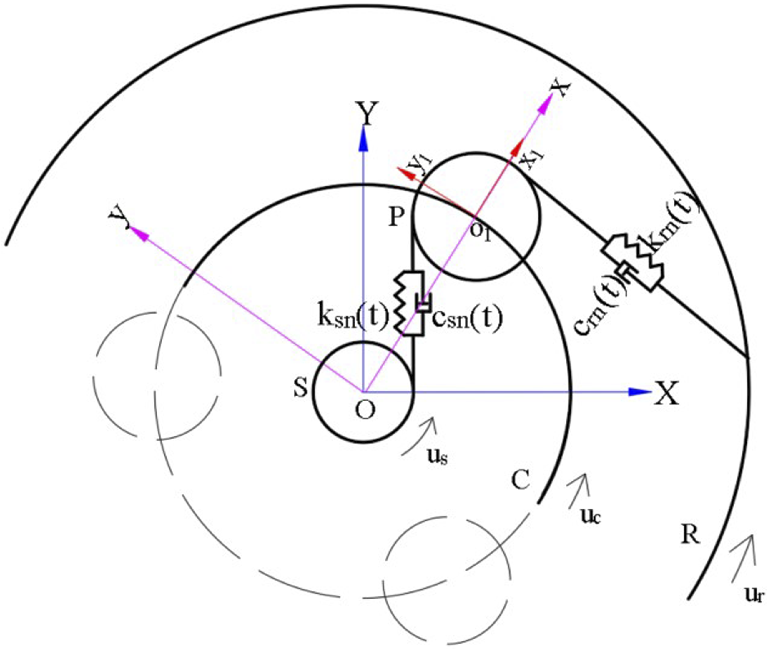
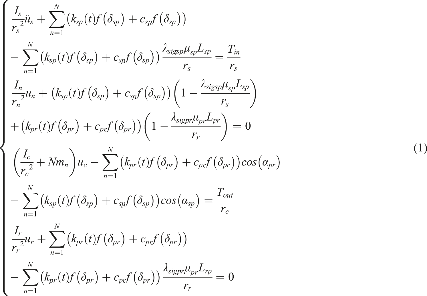
Based on Newton’s laws, the dynamic differential equations of a planetary gear system can be derived
16


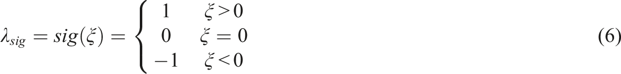
In the process of moving the meshing point along the meshing line, when the meshing point passes through the pitch node, the relative sliding speed of the meshing tooth surface changes in the direction, so the direction transformation coefficient is adopted to reflect this behavior, which can be expressed as
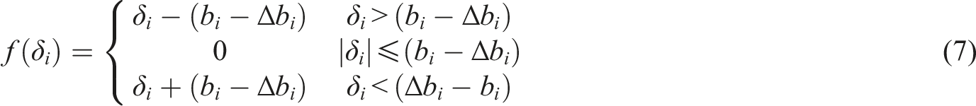
The tooth side clearance plays a crucial role in introducing significant nonlinearity into gear systems. During the manufacturing and assembly processes of gears, it is essential to maintain a specific gap between meshing teeth to ensure adequate lubrication and prevent issues such as gear jamming caused by thermal expansion. The tooth side clearance can be represented using a piecewise function.
20
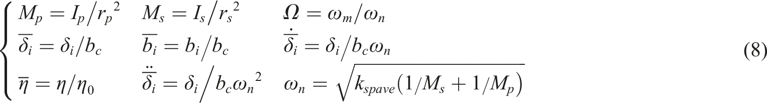
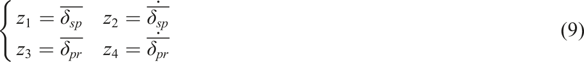
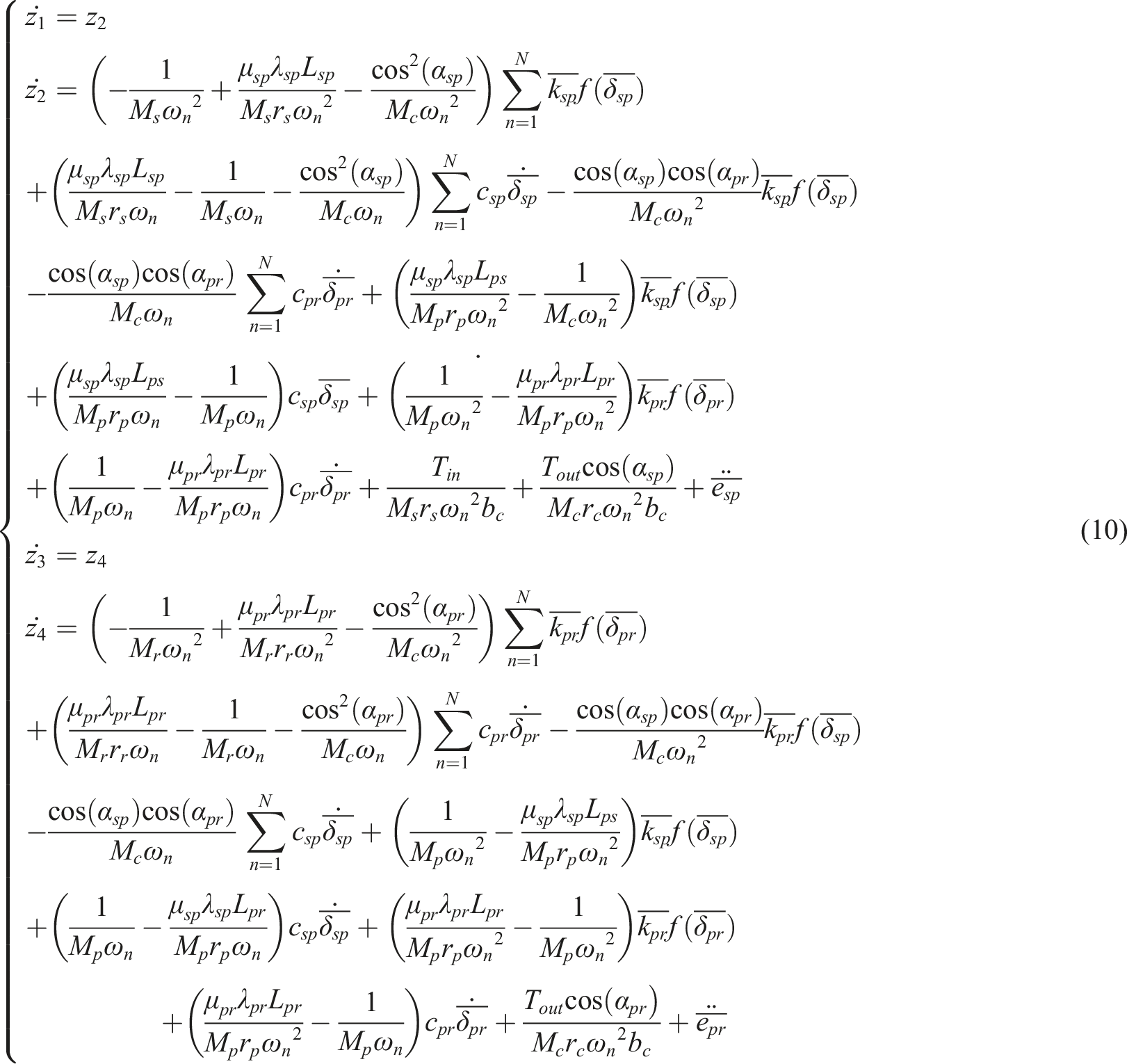
In order to facilitate subsequent solution and analysis, the vibration displacement in the dynamics equation is changed into relative displacement by formula (2), and dimensionless parameters in formula (8) are selected, and the system is transformed into dimensionless equation of state by formula (9), as shown in formula (10).
20
Steady-state temperature field of planetary gear system
Steady-state temperature field calculation model of planetary gear
In the process of gear meshing transmission, the main sources of heat are the elastic-plastic deformation of the teeth, rolling and relative sliding between the meshing tooth surfaces, with relative sliding accounting for a major portion.
24
The heat flux generated by sliding friction is related to contact stress on gear tooth mating surfaces, relative sliding velocity between meshing tooth surfaces, friction coefficient, thermal conversion coefficient, and load distribution factor. It can be expressed as
5

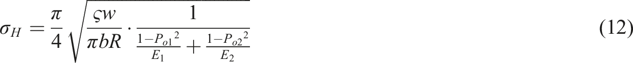
A pair of meshing gears can be equivalently represented as two contacting cylinders. In practical gear contact, there exists a contact zone between the meshing teeth, where the contact stress is distributed in an elliptical shape along the normal direction of the contact zone. For ease of calculation and analysis, the average contact stress in the contact area is adopted According to contact mechanics, the average contact stress at the point of meshing is
5
Load distribution coefficient of SP and PR meshing pairs.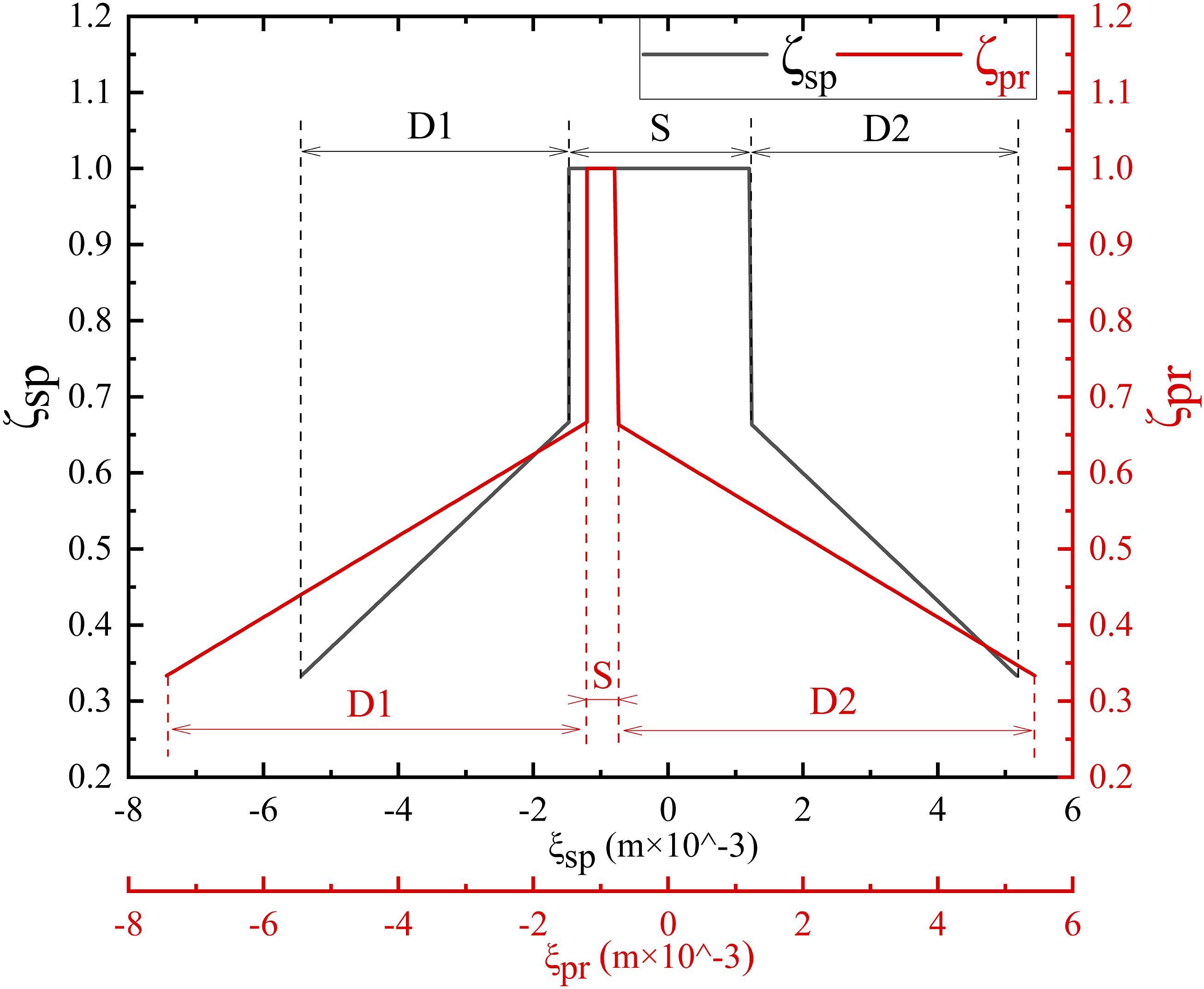
The contact stress of SP and PR meshing pair when the speed is 5000 rpm and the torque is 100 N·m is shown in Figure 3. The contact stress diagram of SP and PR meshing pair when the input speed is 5000 rpm and the torque is 100 N·m.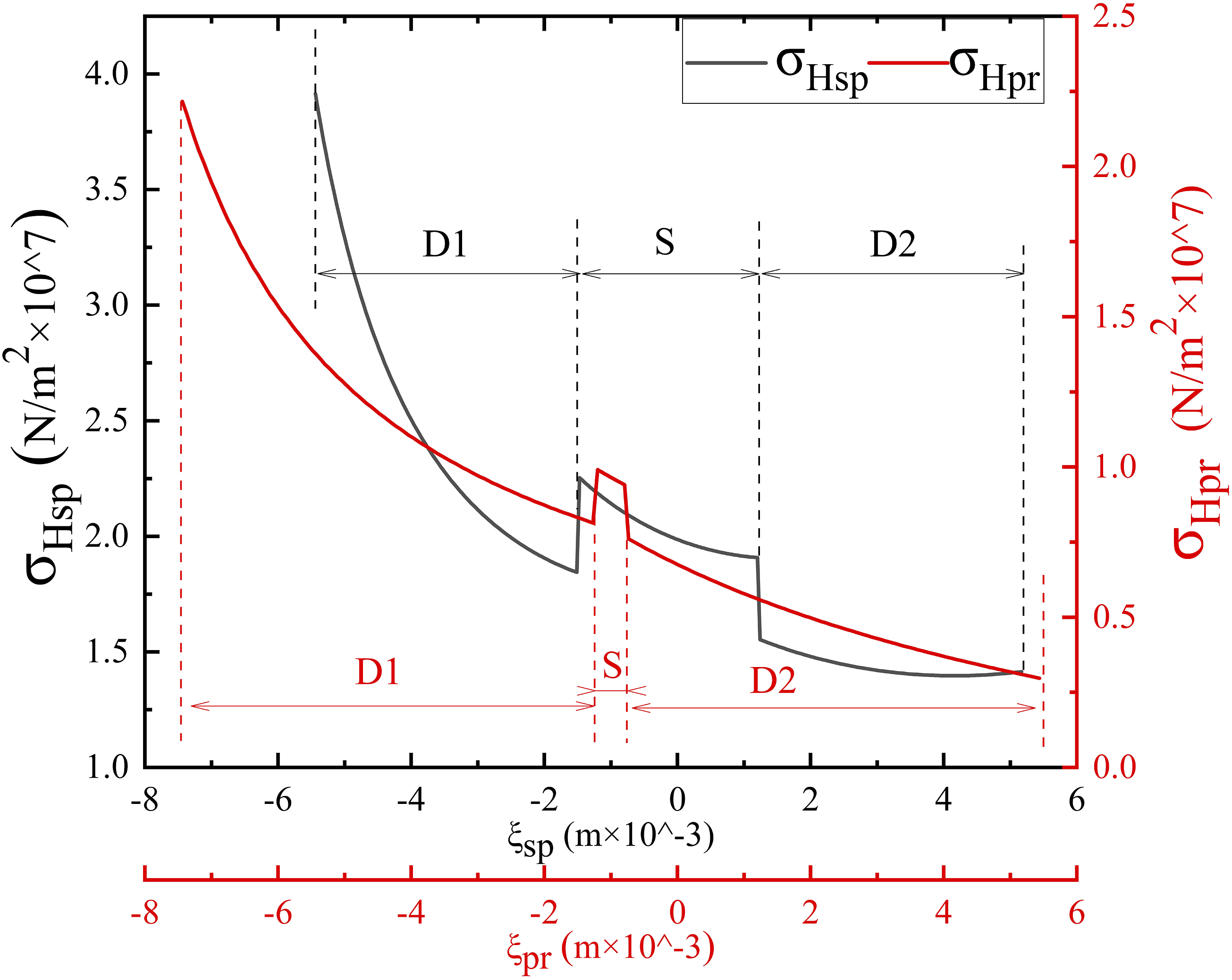
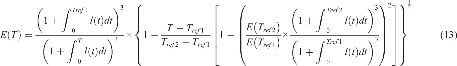
When the temperature changes, the elastic modulus of the gear material also changes, which can be expressed as
25
The friction coefficient between the meshing tooth surfaces can be represented as
26

The frictional heat flux will be distributed to the driving and driven gear through the heat distribution coefficient, as expressed by equation.
27

The frictional heat flux of the driving and driven gear can be expressed as

The heat transfer mechanism on the tooth surface of a straight cylindrical gear is similar to that of bevel gears.
28
The convective heat transfer coefficient on the tooth surface can be calculated for straight cylindrical gears using Handschuh’s convective heat transfer coefficient for bevel gears,
5
as proposed by several scholars5,29–31

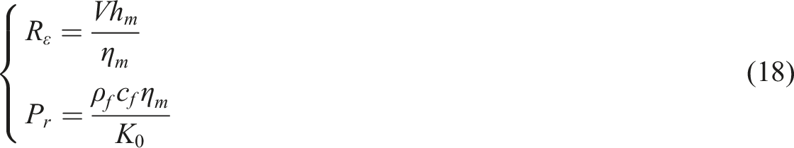
Reynolds number and Prandtl number can be expressed as
5
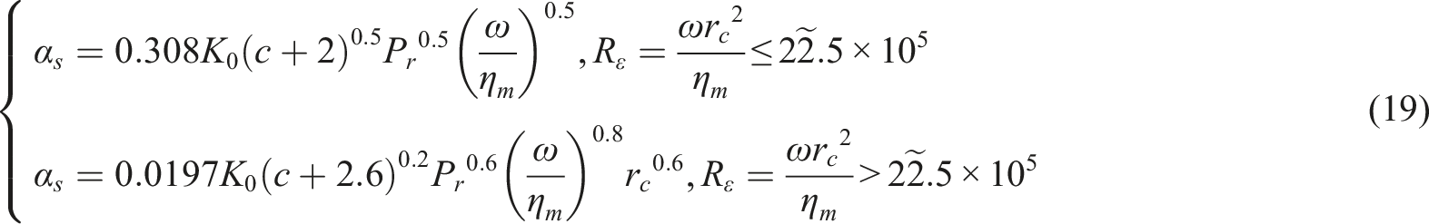
The convective heat transfer of the gear face can be equivalent to the convective heat transfer coefficient of the disc when the disc rotates in the lubricating oil. The flow state of the lubricating oil on the surface of the disc can be divided into laminar flow (Re < 1) and turbulent flow (Re ≥ 1), and different Reynolds number ranges correspond to the convective heat transfer coefficients under different flow states.
32
Simulation analysis of steady-state temperature field of planetary gear
In practical operating conditions, planetary gears often encounter diverse working scenarios. This article defines two sets of working conditions:
Condition 1 involves a fixed input torque of 100 N·m and a speed range from 1000 rpm to 20000 rpm.
Condition 2 entails a fixed input speed of 5000 rpm and a torque range from 100 N·m to 360 N·m.
Utilizing Ansys Workbench’s Steady-Thermal module, the mesh numbers for the sun gear, planet gear, and ring gear are respectively set as follows: 258891, 301380, and 556432, while the node numbers are designated as follows: 530474 for the sun gear, 616070 for the planet gear, and 1128068 for the ring gear.
The temperatures at the pitch circle, base circle, and aperture of the sun gear and planet gear are designated as Temperature change curve of planetary gear system under variable speed condition. Temperature change curve of planetary gear system under variable torque condition.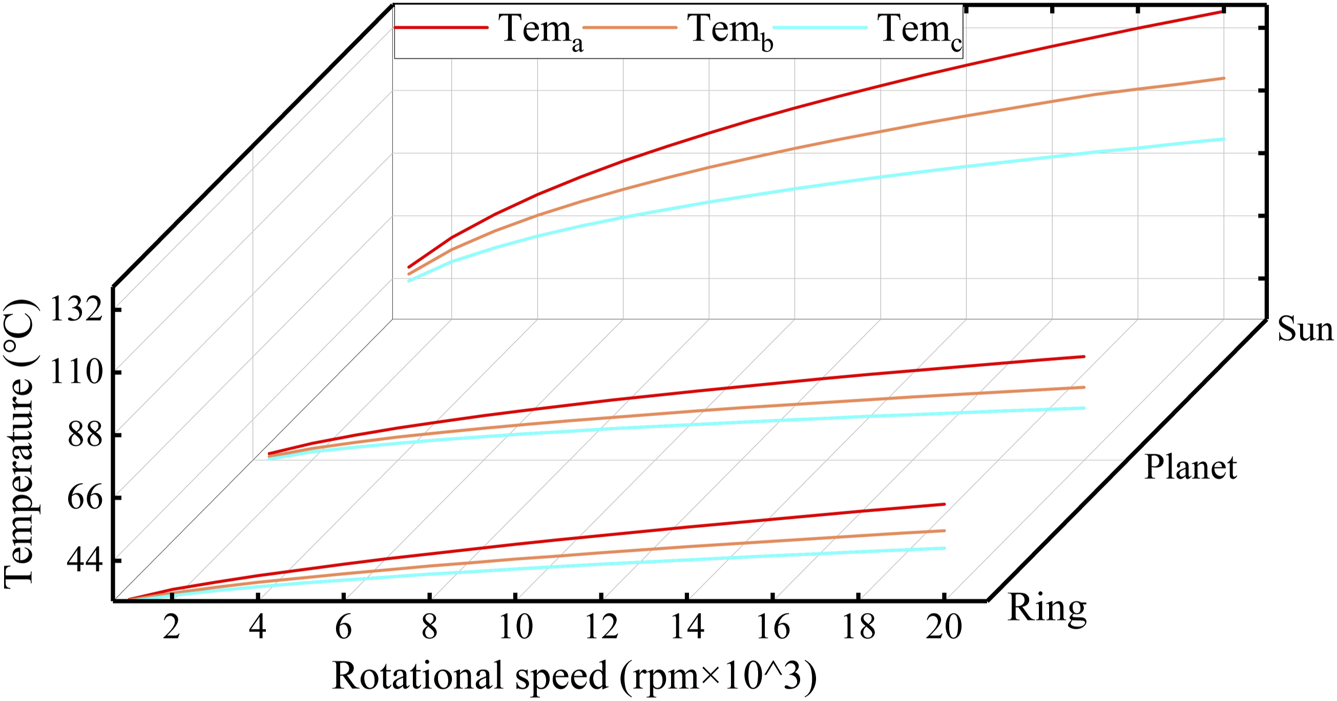
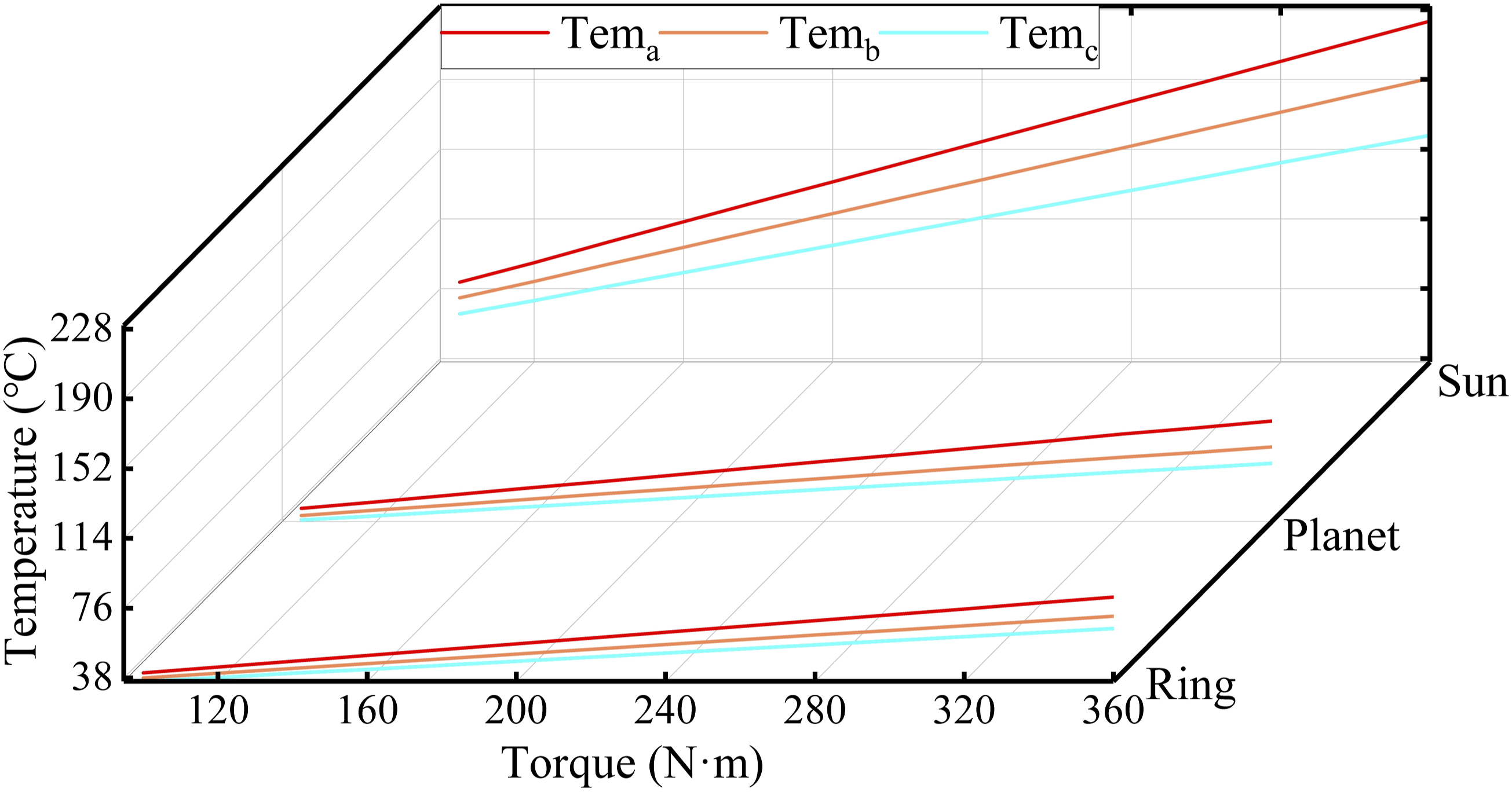
From Figures 4 and 5, it can be observed that under the same operating conditions, the temperature gradually decreases from the sun gear to the ring gear. Under variable speed conditions, the temperature at different positions increases with increasing speed, but the rate of increase gradually diminishes, following a logarithmic pattern. Under variable torque conditions, temperatures in different parts of the system increase linearly with increasing torque. This is because as speed increases, the convective heat transfer coefficient of the system also increases, resulting in more heat exchange with the surroundings and thus reducing the magnitude of temperature rise. On the other hand, an increase in torque does not affect the convective heat transfer coefficient of the system; hence, there is no change in magnitude of temperature rise.
Calculation model for thermal deformation of planetary gear system
Flash temperature of tooth surface
The temperature of the meshing tooth surface consists of two parts: body temperature and flash temperature. The body temperature remains unchanged after the gear reaches a steady state. Flash temperature is a transient increase in tooth surface temperature caused by energy loss due to mutual friction between meshing tooth surfaces.
33
Flash temperature is determined by the relative sliding speed, load, and material parameters of the meshing tooth surfaces, and can be expressed as
34


The half-width

The curvature radius

The pressure angle at the point of engagement can be expressed as
35

Thermal deformation calculation model
The thermal deformation calculation principle of external meshing gear has been elaborated in literature,1,2 and its thermal deformation calculation model is as follows:


For the ring gear, its thermal deformation is shown in the Figure 6. Ring gear thermal deformation diagram.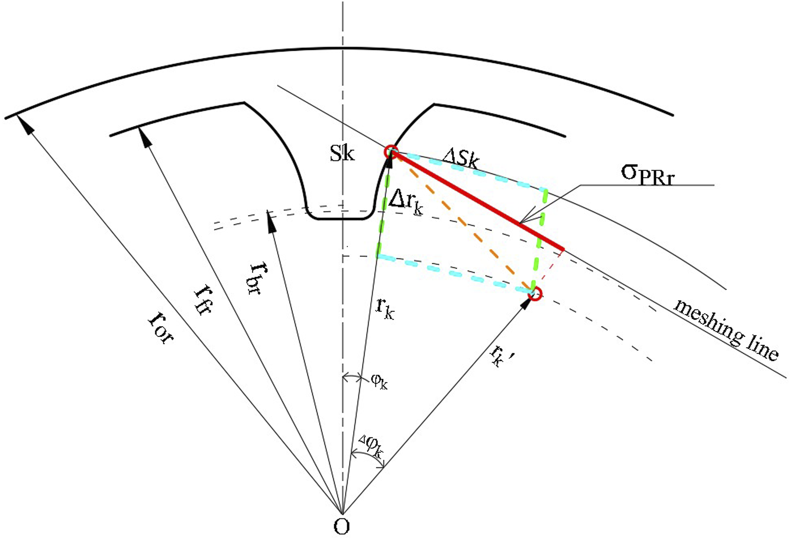
Thermal deformation of the ring gear can be regarded as comprising two components: circumferential deformation and radial deformation. The circumferential deformation, which occurs along the direction of tooth thickness after heating, can be mathematically expressed as

The temperature of the contact point


The change in the angle of extension caused by thermal deformation

The radial deformation of the gear can be regarded as comprising two components: the radial deformation of the gear body and the radial deformation of the teeth. The radial deformation of the gear body can be mathematically represented as

The radial deformation of the gear tooth can be represented as

The distance from the contact point to the center of the gear after thermal deformation can be expressed as

The comprehensive thermal deformation of the gear can be formulated as

Verification of thermal deformation calculation model of ring gear
In order to validate the accuracy of the proposed gear thermal deformation calculation model, a working condition with a rotational speed of 5000 rpm and torque of 100 N·m was specifically chosen. The steady-state temperature field values of the gear were utilized as loads in ANSYS static structural module to obtain simulated data on thermal deformation of gear teeth. A comparison was made between the simulation value and calculated value. The obtained results are illustrated in the Figure 7. Comparison of calculated and simulated thermal deformation values of gear ring.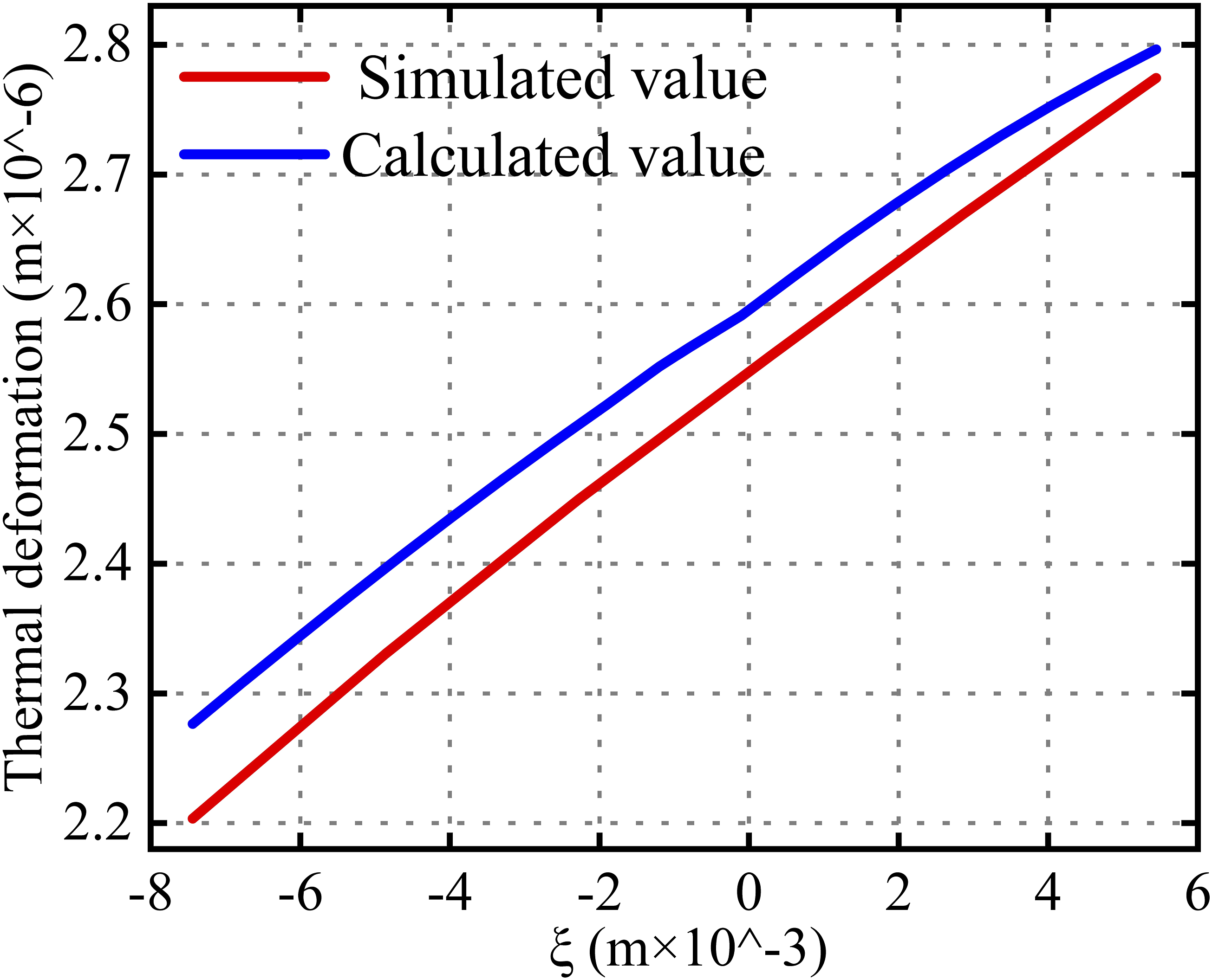
The trend of the theoretical calculated values is observed to be consistent with the simulated values along the meshing line, as depicted in Figure 7. The tooth deformation of the gear gradually increases from the root to the tip, which aligns with previous studies.5,7 However, a comparison between the results reveals that the calculated values are slightly larger than the simulated values. This discrepancy can be attributed to neglecting other directions influenced by material continuity, such as tooth width direction, in the theoretical calculation model where only radial and circumferential thermal deformations were considered. Additionally, in simulation calculations, fixed support was applied at the outer wall of the ring gear (i.e., zero thermal deformation), leading to slightly larger calculated values compared to simulated ones. In conclusion, numerical models yield similar trends and exhibit minor differences when compared to simulated values, thereby verifying the accuracy of our numerical calculation model.
Analysis of system backlash variation under the influence of thermal deformation
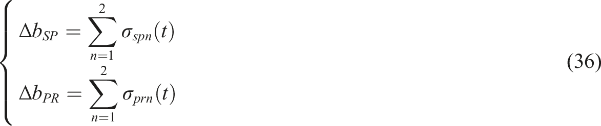
The change in backlash of the SP meshing pair and PR meshing pair caused by thermal deformation can be expressed as
The changes in backlash of the SP meshing pair and PR meshing pair under variable speed conditions and variable torque conditions are shown in Figures 8 and 9, respectively. Backlash variation of planetary gear system under variable speed conditions. (a) Backlash variation of SP and (b) Backlash variation of PR. Backlash variation of planetary gear system under variable torque conditions. (a) Backlash variation of SP and (b) Backlash variation of PR.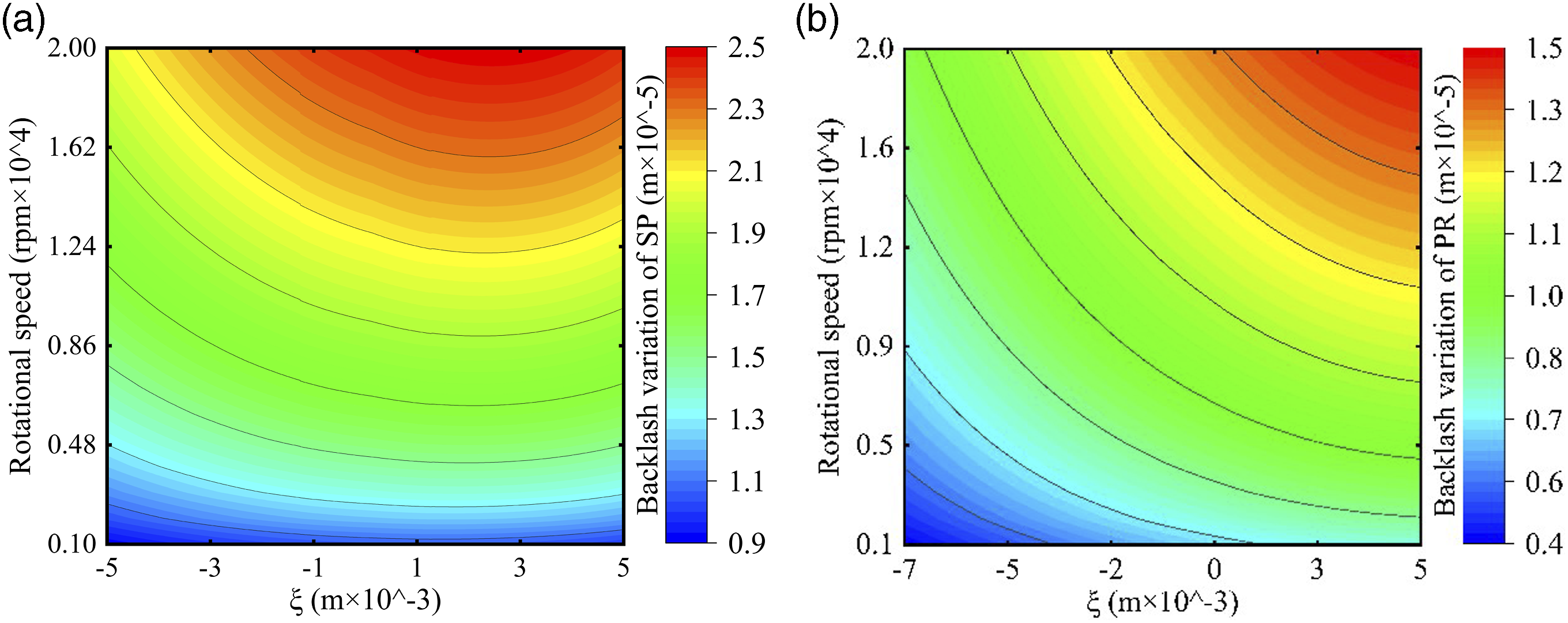
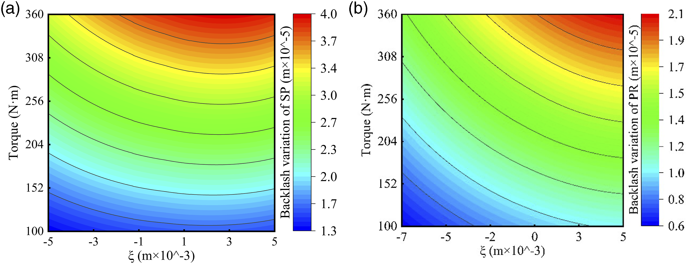
The variation of backlash gradually increases along the line of engagement, as observed from Figures 8 and 9. The maximum value of backlash variation for the SP meshing pair is found near the tooth tip, while for the PR meshing pair, it occurs at the tooth top position. Under similar operating conditions, the backlash variation is greater for SP meshing compared to PR meshing. Figure 8 indicates that under variable speed conditions, the contour lines of backlash variation become more widely spaced with increasing speed, suggesting a gradual decrease in magnitude of backlash variation. Conversely, Figure 9 demonstrates that there is a constant spacing between contour lines of backlash variation with increasing torque, indicating a linear relationship between backlash variation and torque.
Analysis of system coupling stiffness under the influence of thermal deformation
The thermal stiffness of gear teeth caused by thermal deformation can be expressed as

The thermal stiffness of the meshing pair, derived from the tooth contact thermal stiffness, can be expressed as

The coupled meshing stiffness obtained after the coupling of thermal stiffness and meshing stiffness can be represented as

The variations in coupling meshing stiffness of the gear pair are illustrated in Figures 10 and 11 under conditions of variable speed and torque. Coupling stiffness of planetary gear system under variable speed conditions. (a) Coupling stiffness of SP and (b) Coupling stiffness of PR. Coupling stiffness of planetary gear system under variable torque conditions. (a) Coupling stiffness of SP and (b) Coupling stiffness of PR.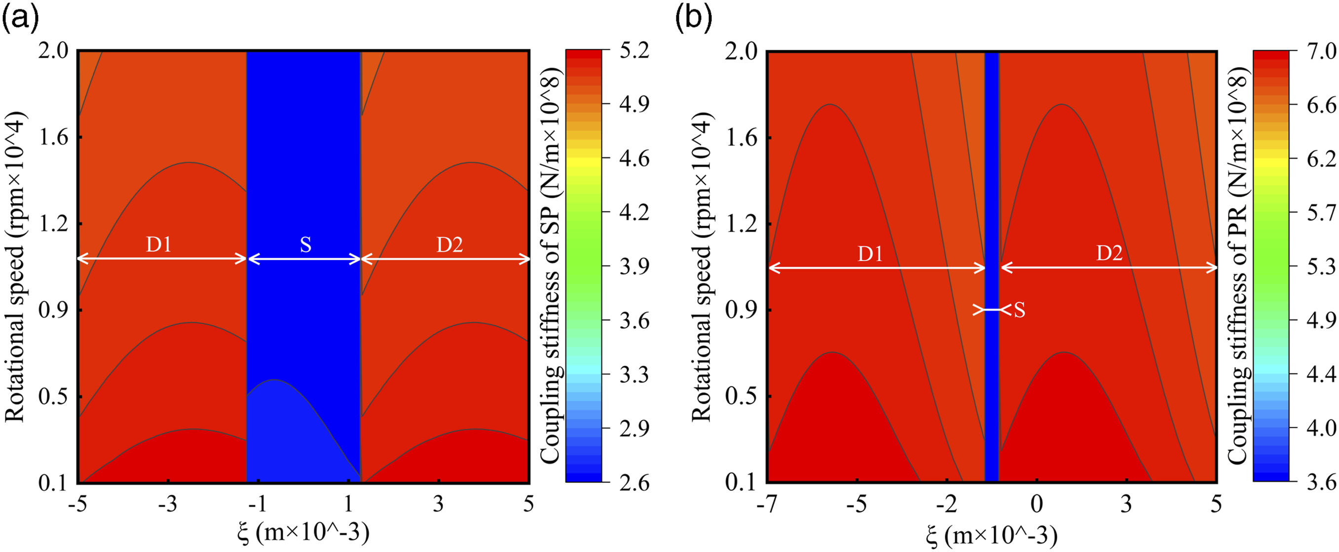
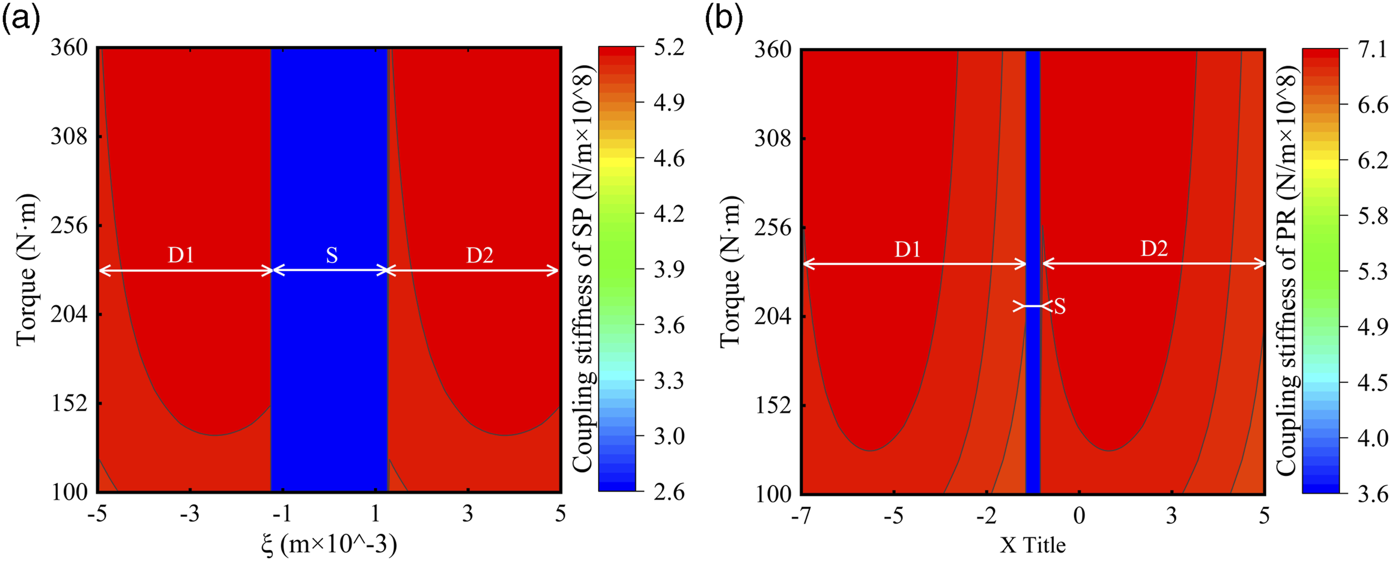
The coupling mesh stiffness of the SP is observed to be smaller than that of the PR under identical operating conditions, as evident from Figures 10 and 11. When subjected to variable speed conditions, the coupling stiffness decreases with an increase in rotational speed. Conversely, under variable torque conditions, the coupling stiffness increases with higher torque.
Analysis of nonlinear dynamical characteristics of the system
Nonlinear dynamic analysis of system under variable speed conditions
Choose the dimensionless meshing frequency as the bifurcation parameter and assign values to parameters
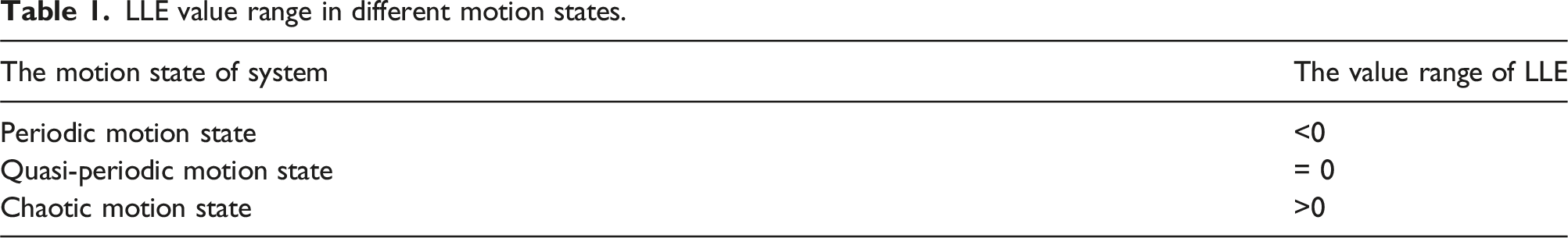
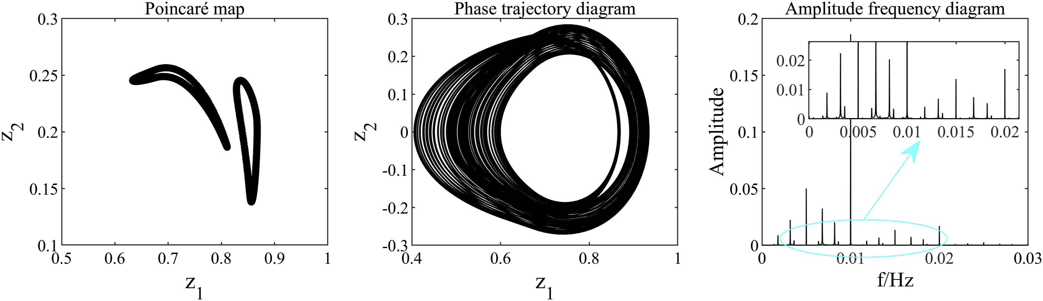
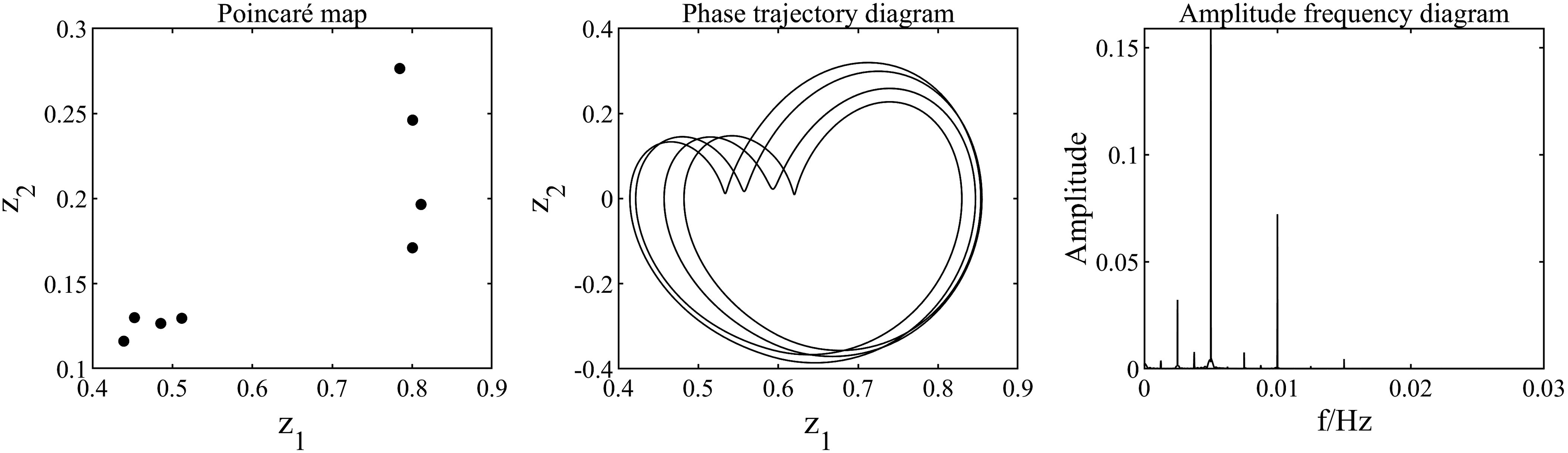
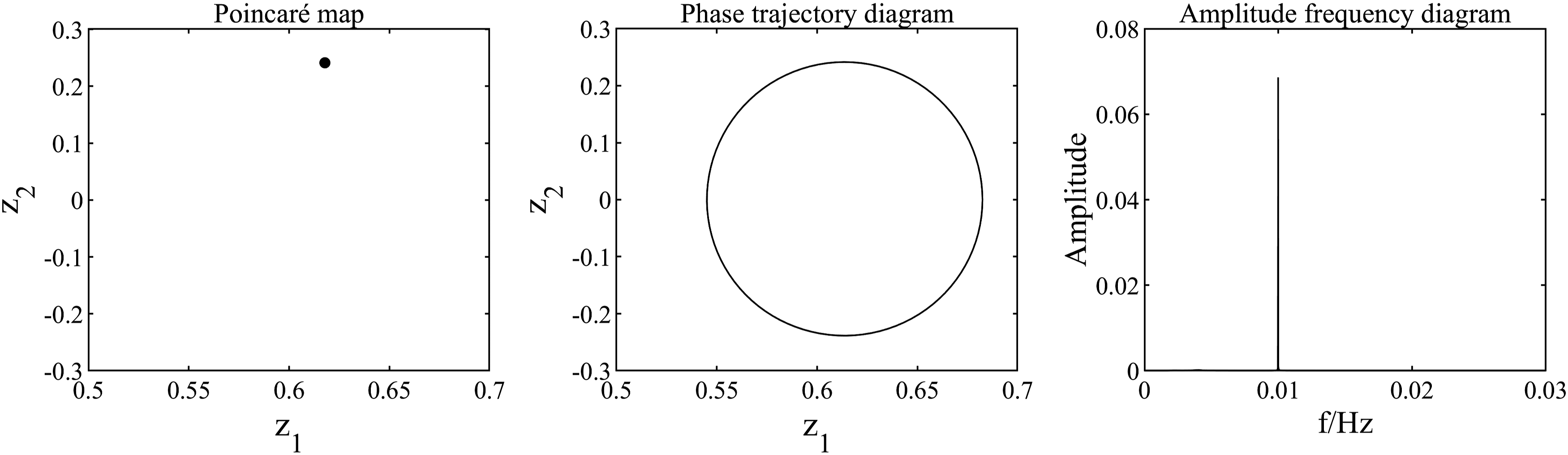
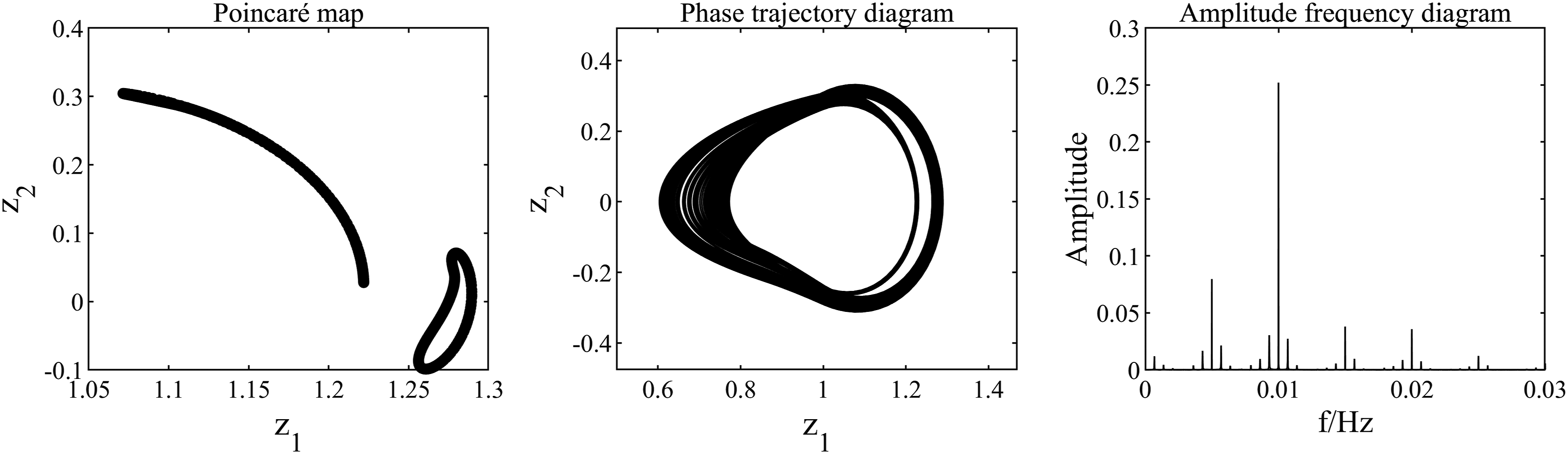
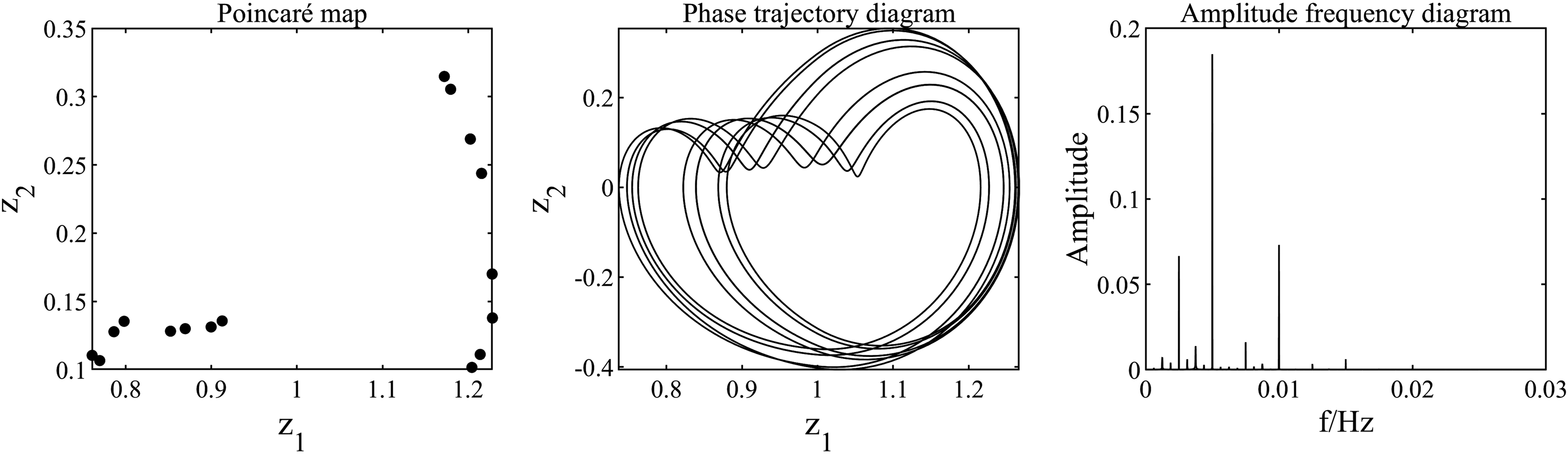
The bifurcation diagram and LLE graph of the system are presented in Figure 12, respectively. The maximum Lyapunov exponent (LLE) serves as a crucial indicator for evaluating the stability of the system, with its values being associated with different states of the system as demonstrated in Table 1. Specifically, a negative, zero, or positive LLE corresponds to periodic motion state ( Bifurcation diagram and LLE diagram of system under variable speed condition. LLE value range in different motion states.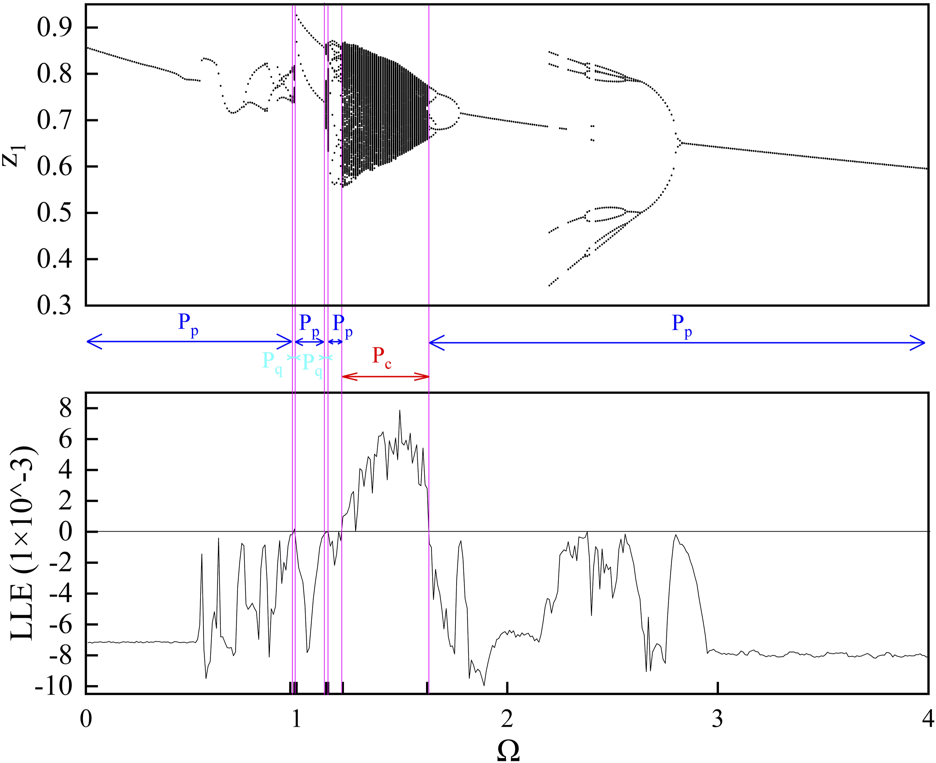
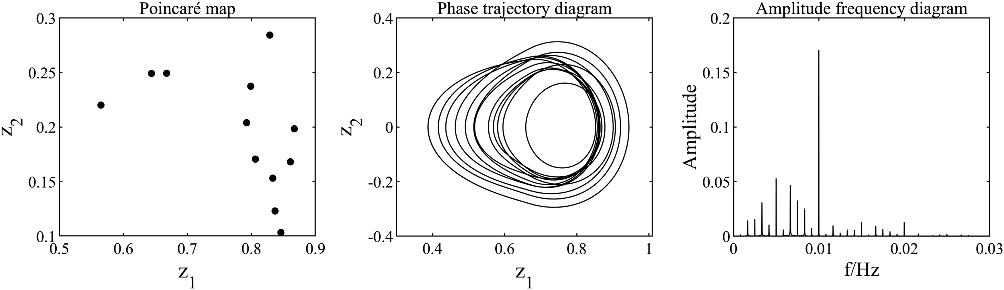
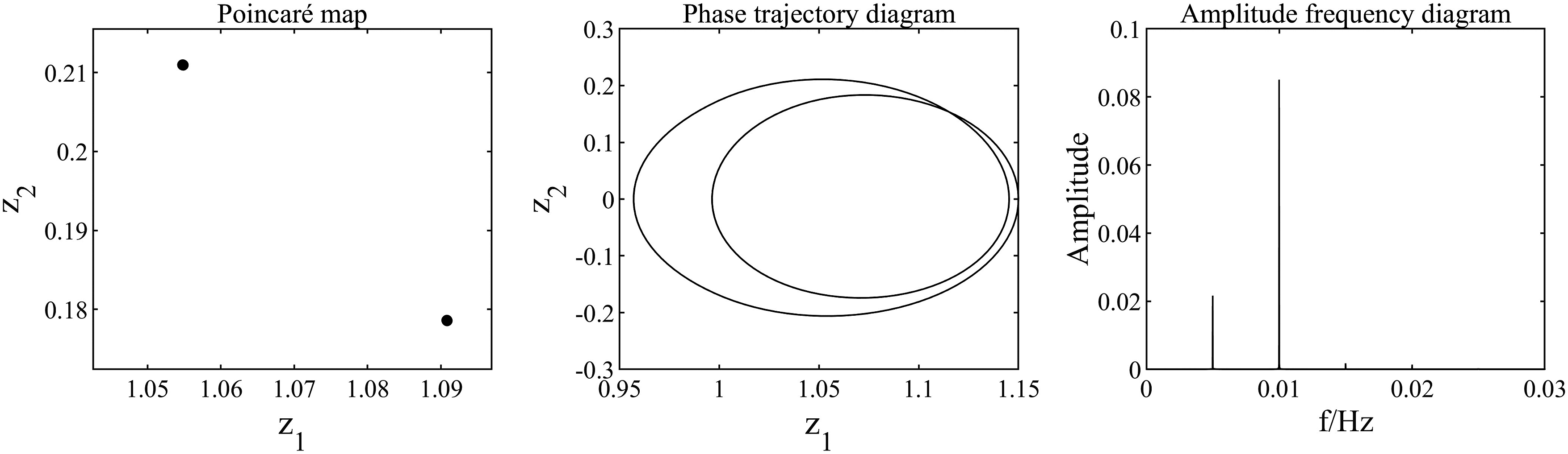
When P1 motion state of the System when P2 motion state of the System when P4 motion state of the System when 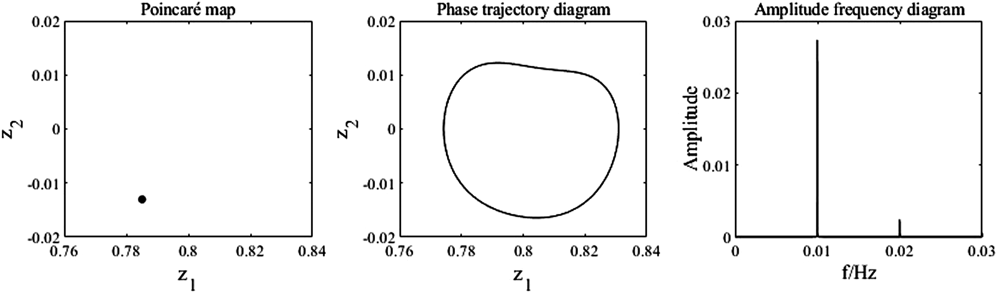
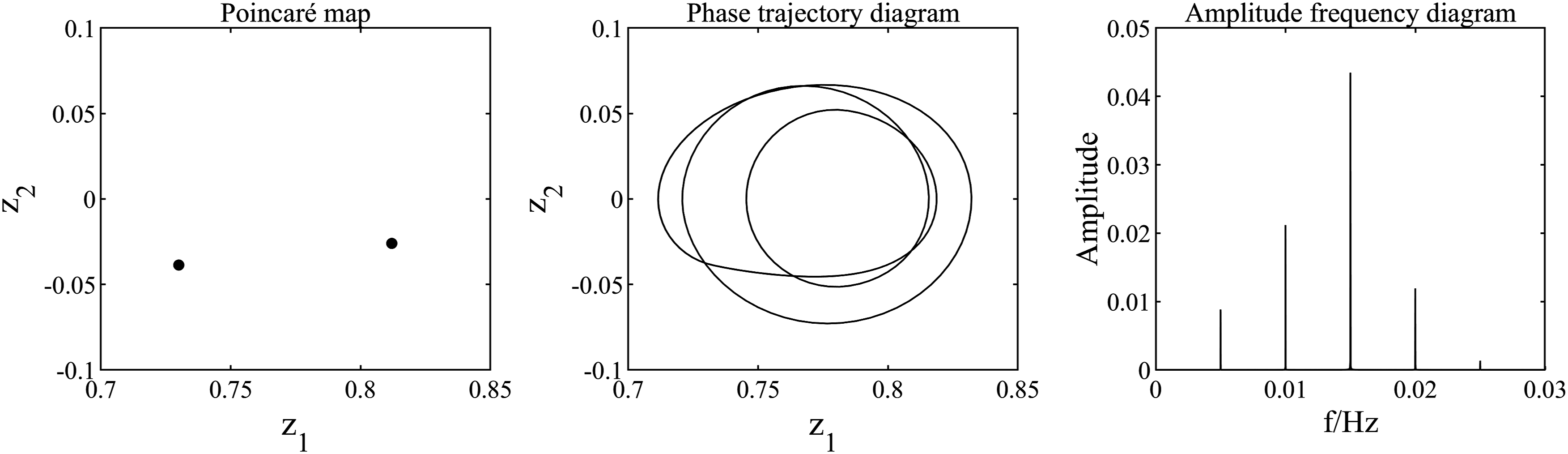
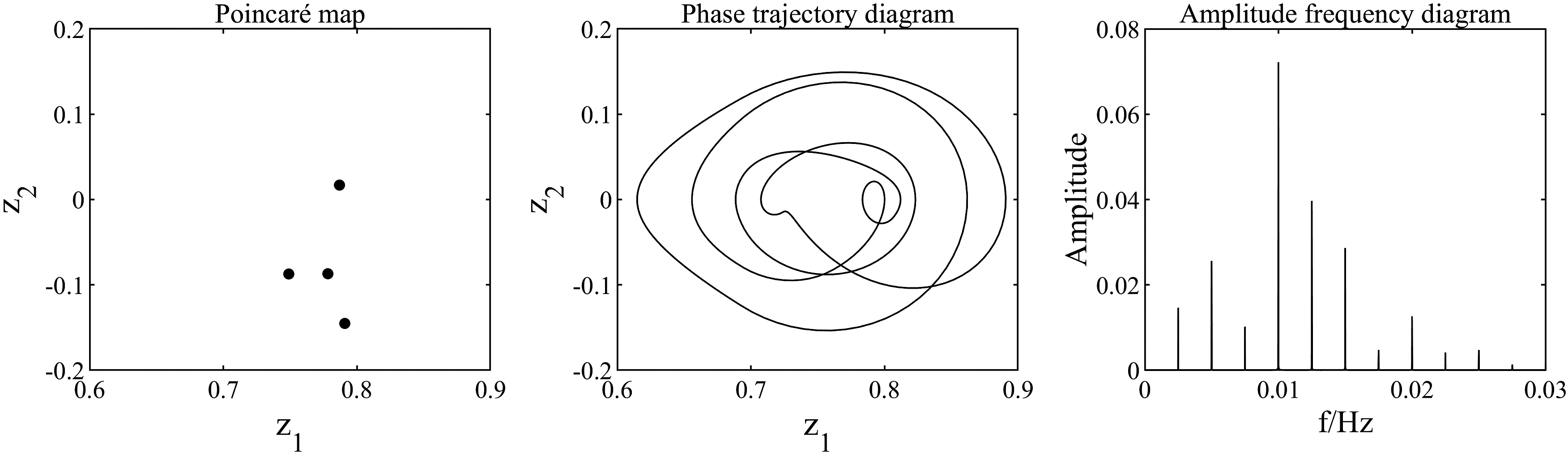
When Quasi-P4 motion state of the system when 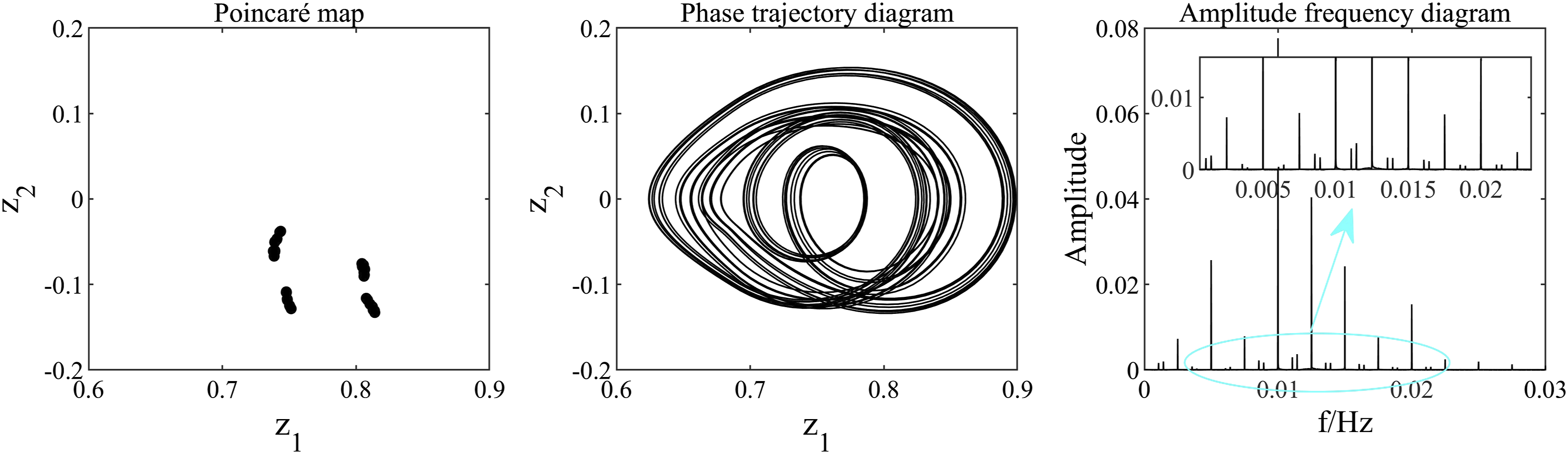
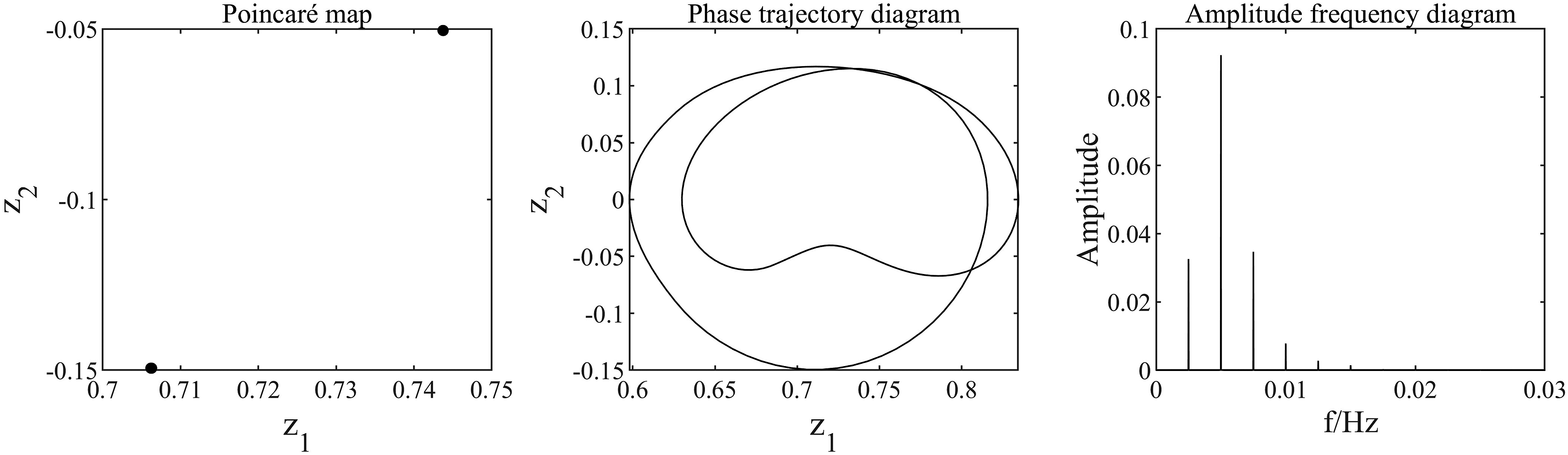
When P2 motion state of the system when Quasi-P2 motion state of the system when P12 motion state of the system when 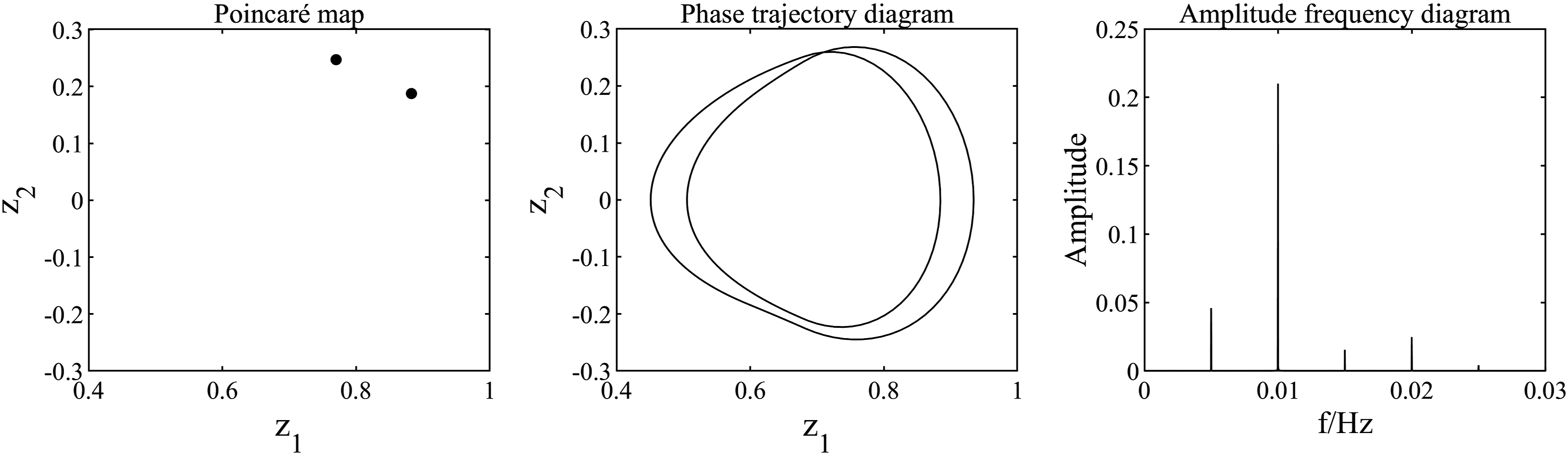
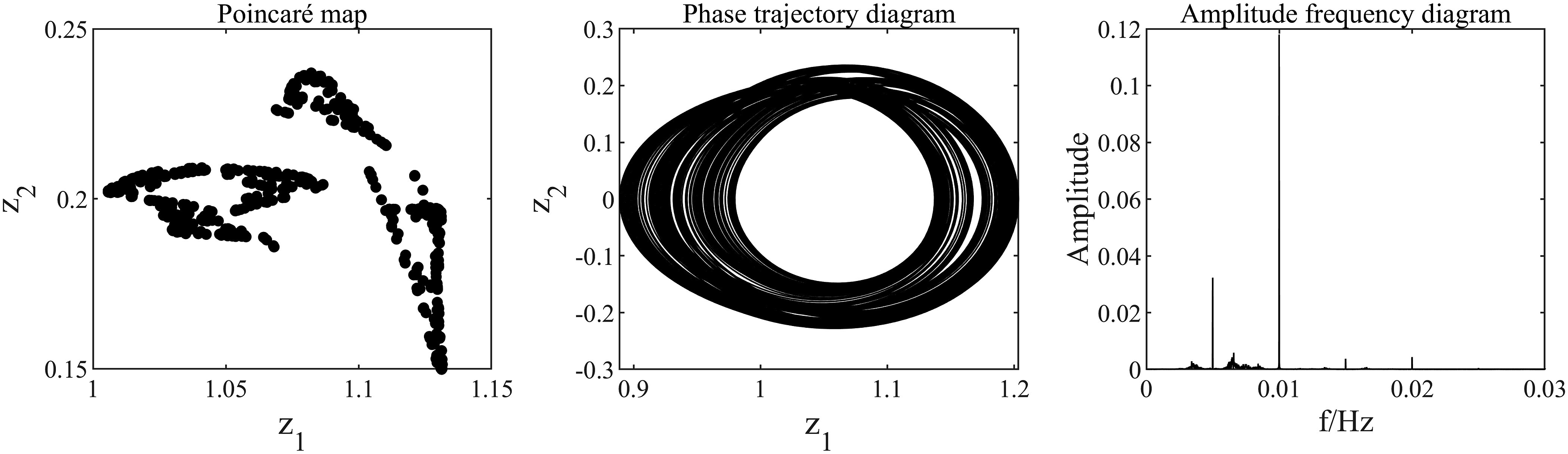
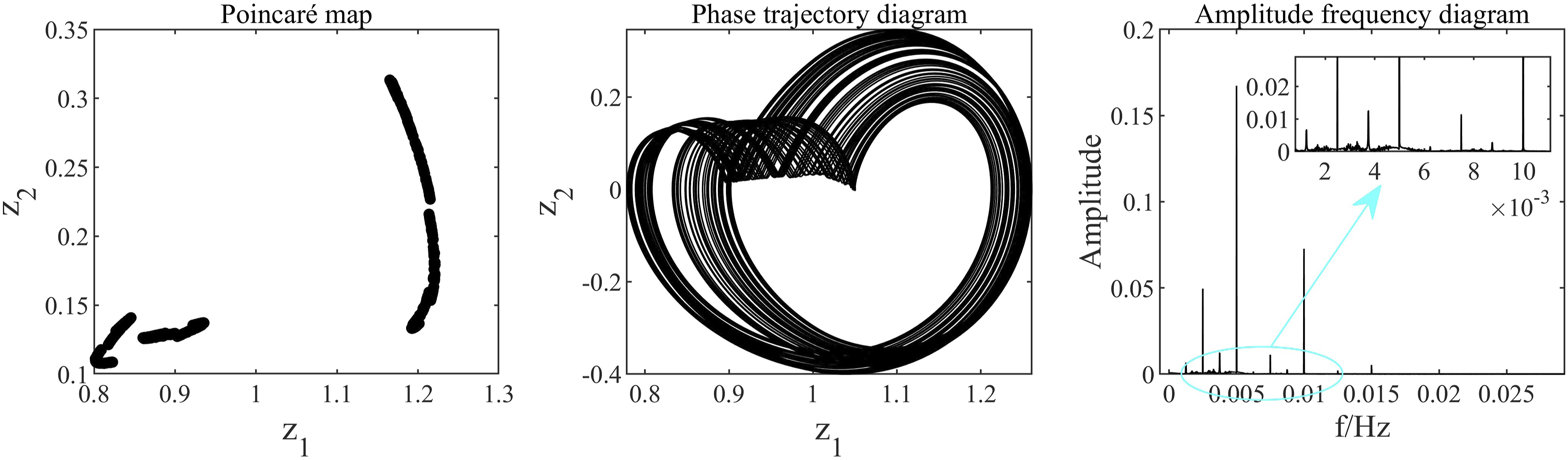
When Chaotic motion state of the system when 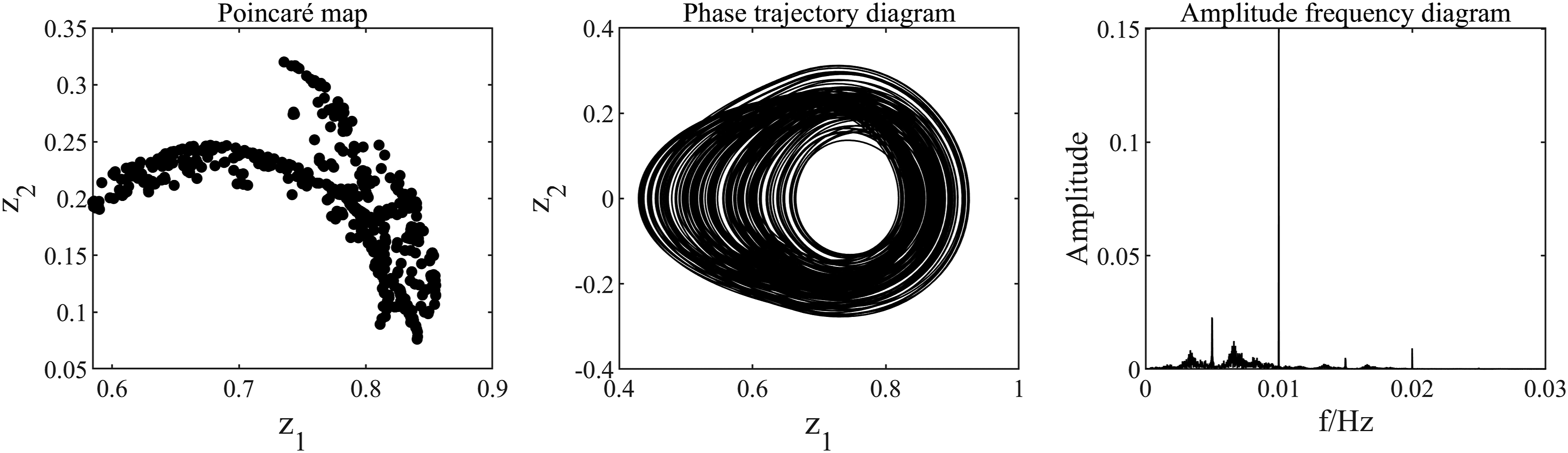
When P4 motion state of the system when P8 motion state of the system when P1 motion state of the system when 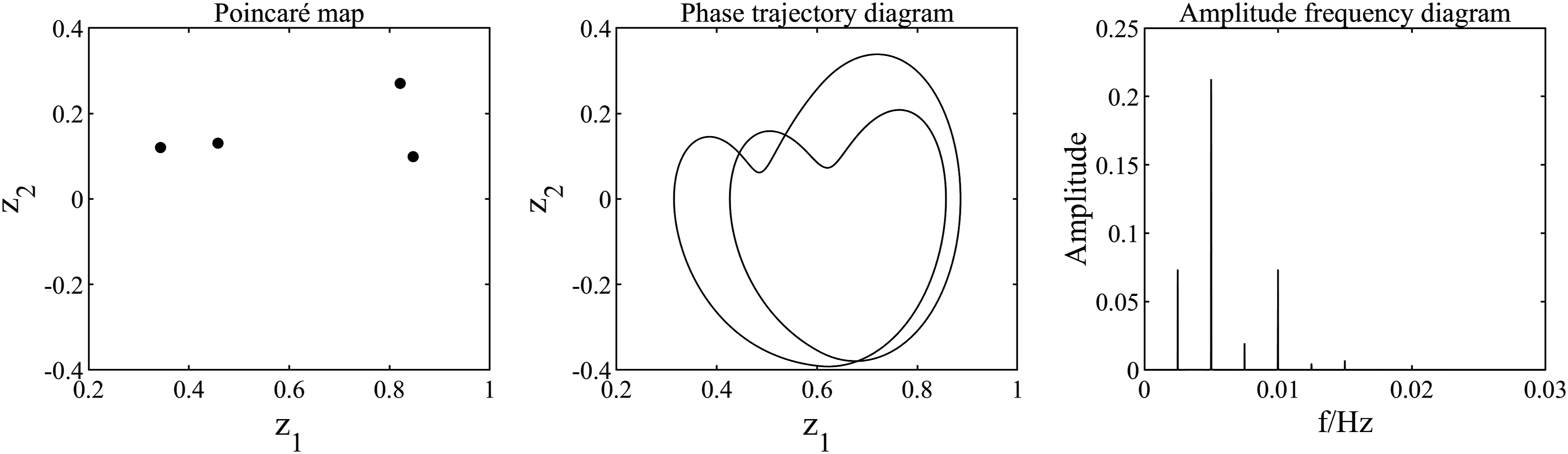
Analysis of the influence of thermal deformation on the system under variable speed conditions
Influence on the meshing impact state of the tooth surface
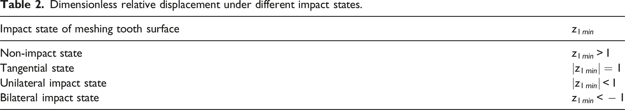
During the meshing process, there are impact types on the meshing tooth surface, such as non-impact state, tangential state, unilateral impact state, and bilateral impact state. The relationship between impact state and dimensionless relative displacement is as follows 35
The original system (without considering thermal deformation) undergoes a transition from a non-impact state to a unilateral impact state at Phase trajectory diagram of the original system when Dimensionless relative displacement under different impact states. Nomenclature.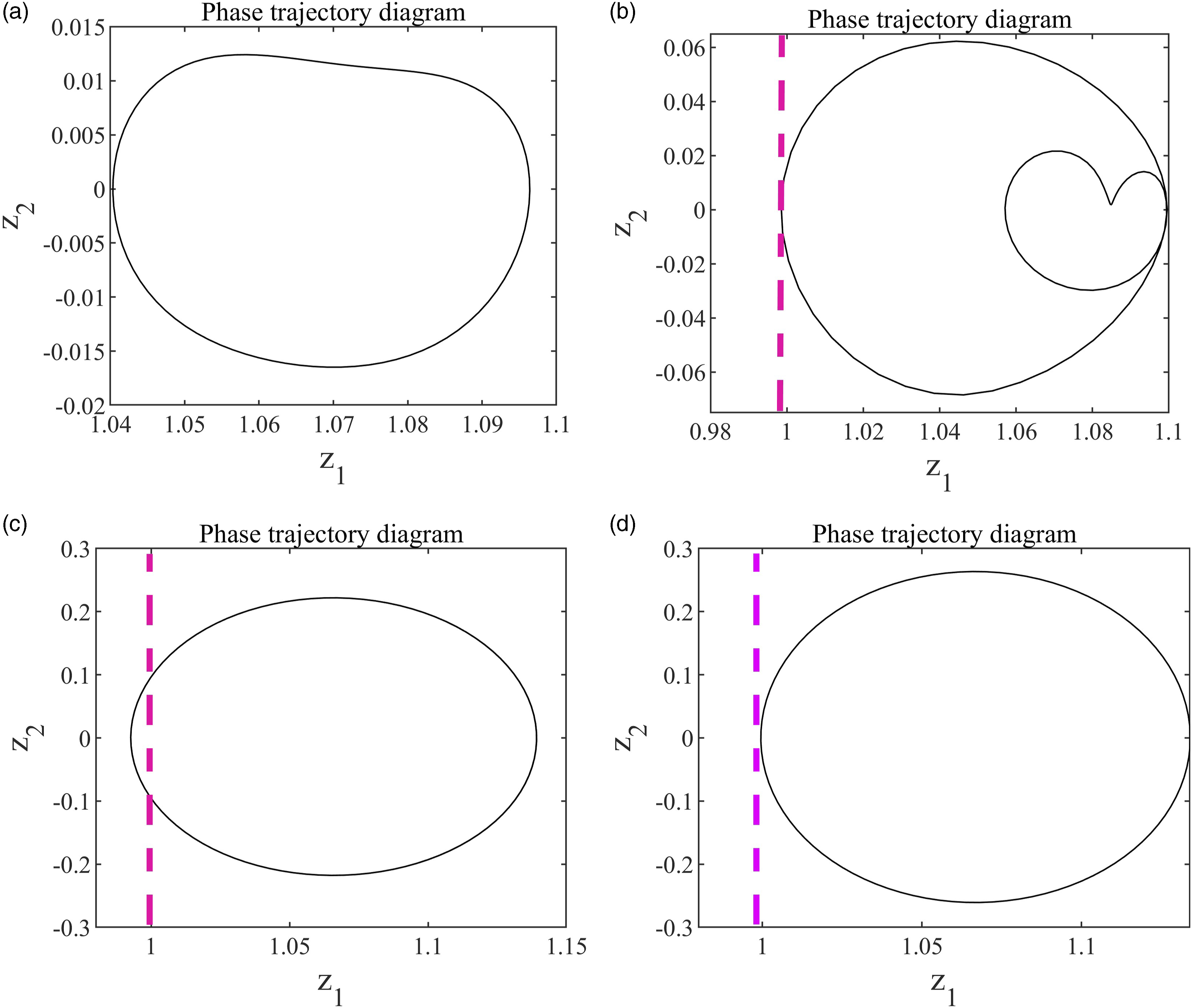
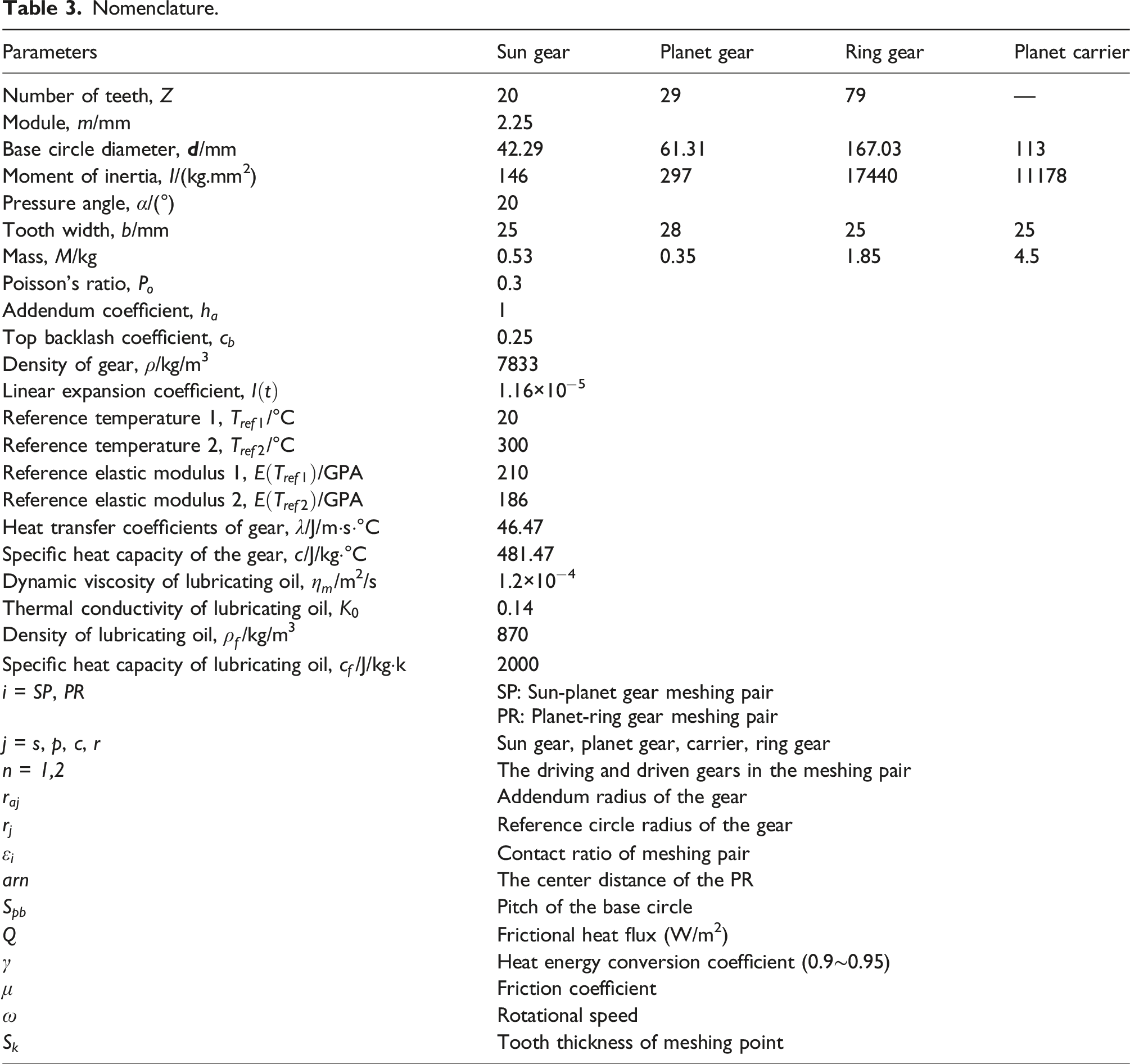
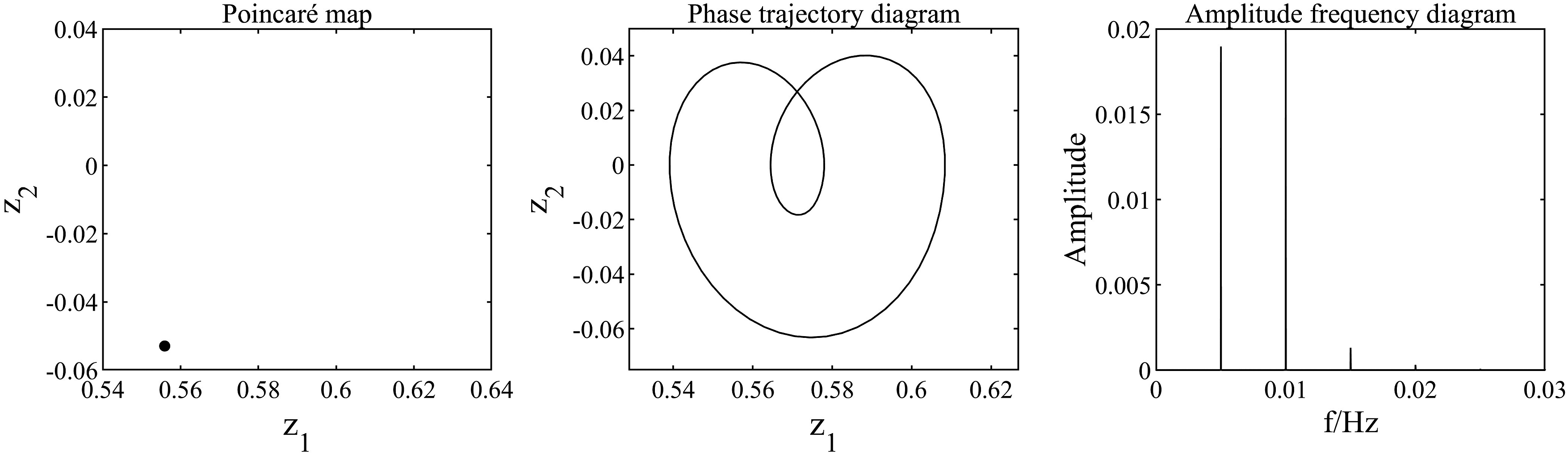
Selecting the phase diagram at Phase trajectory diagram of the thermal system when 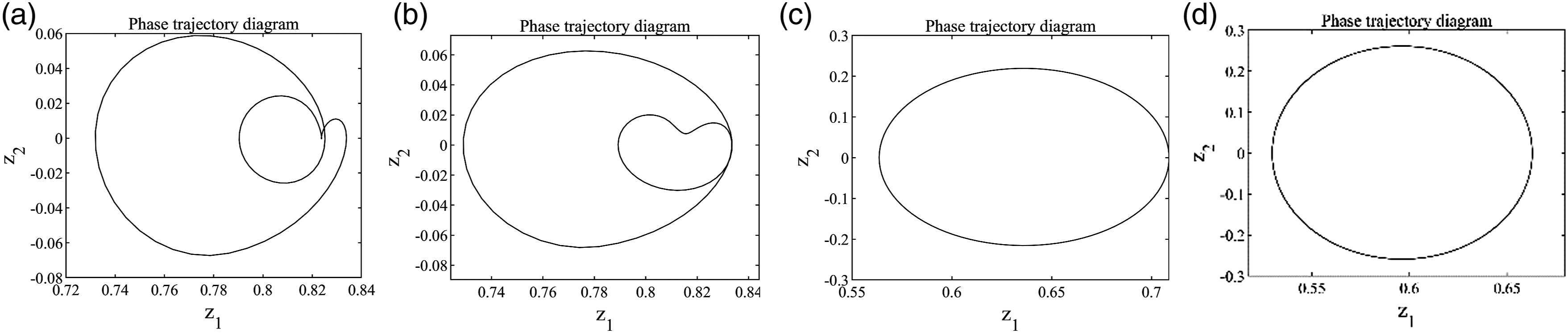
Influence on the system motion status
When P4 motion state of the thermal system when P2 motion state of the original system when 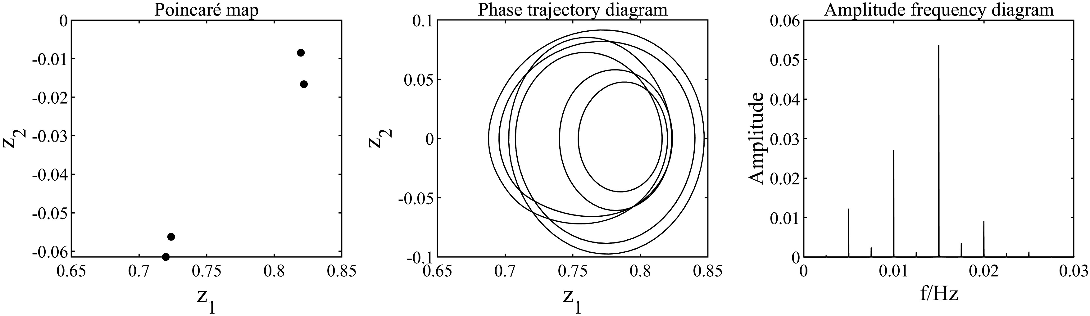
When P4 motion state of the thermal system when Quasi-P2 motion state of the original system when 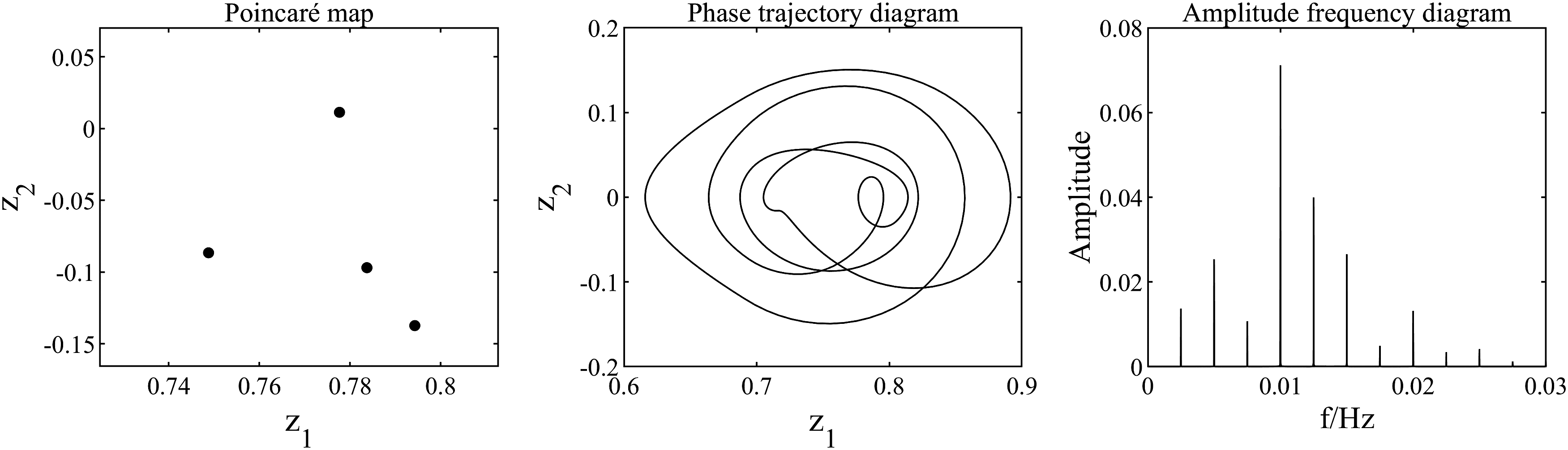
When P24 motion state of the thermal system when Chaotic motion state of the original system when 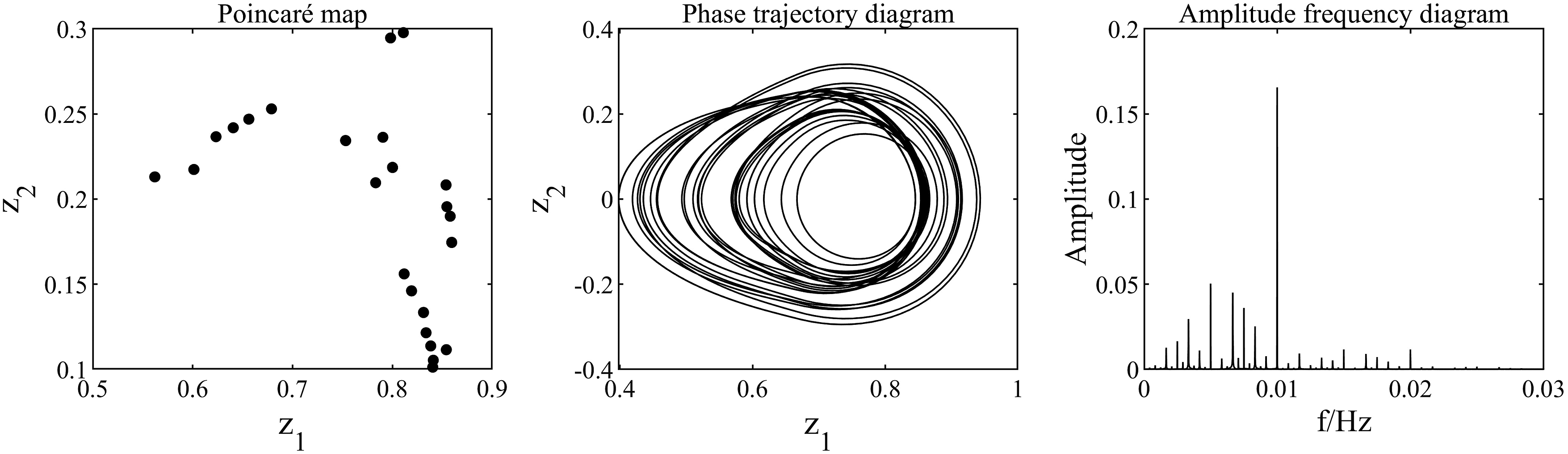
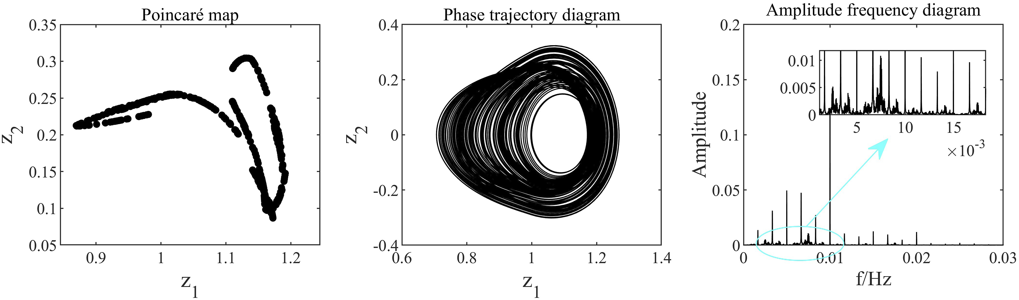
When P10 motion state of the thermal system when Chaotic motion state of the original system when 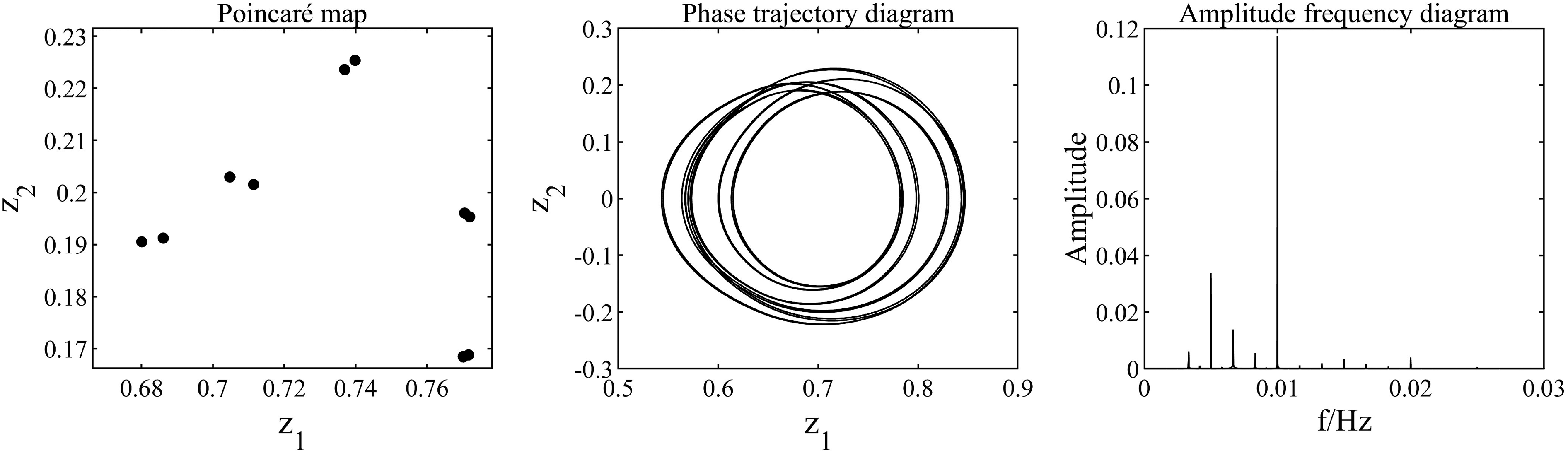
When P1 motion state of the thermal system when P2 motion state of the original system when 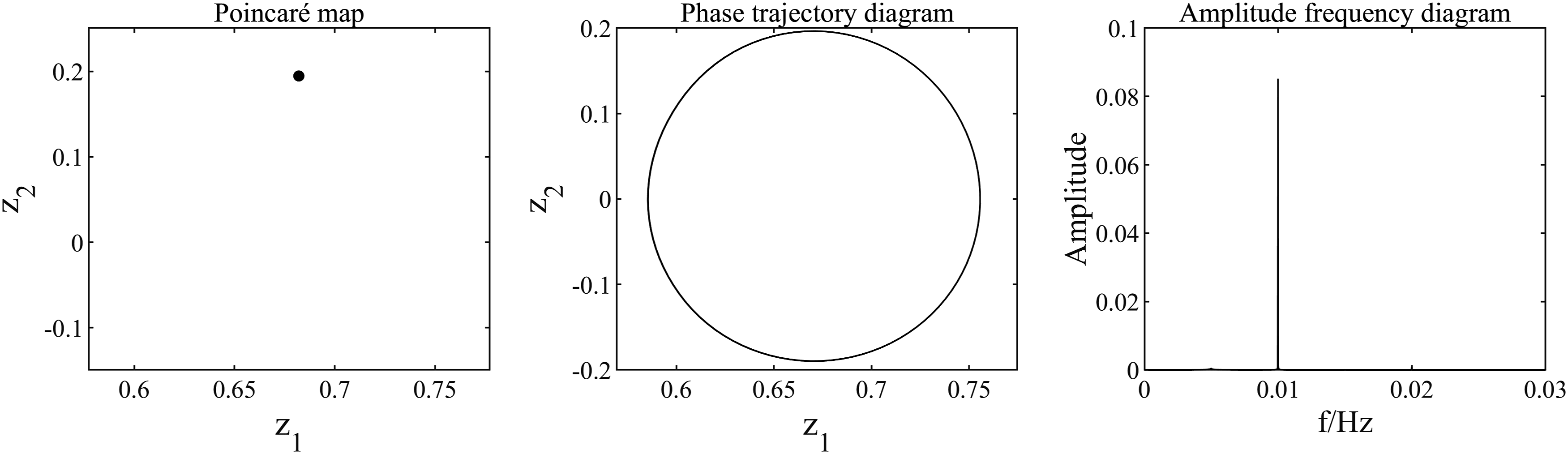
When P4 motion state of the thermal system when P16 motion state of the original system when 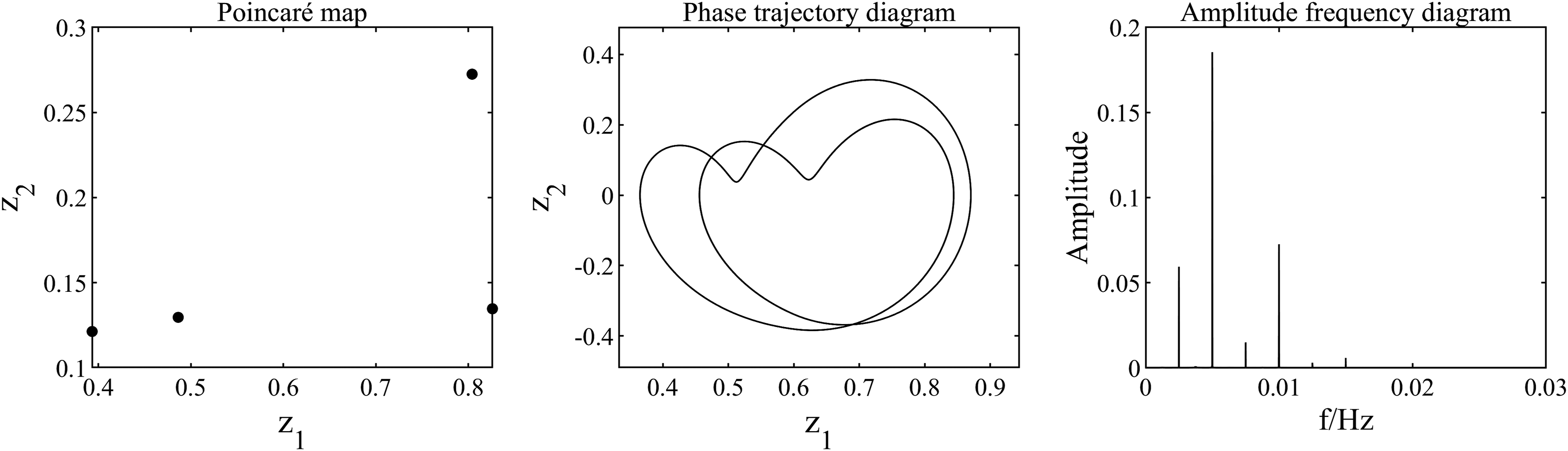
When P8 motion state of the thermal system when Quasi-P4 motion state of the original system when 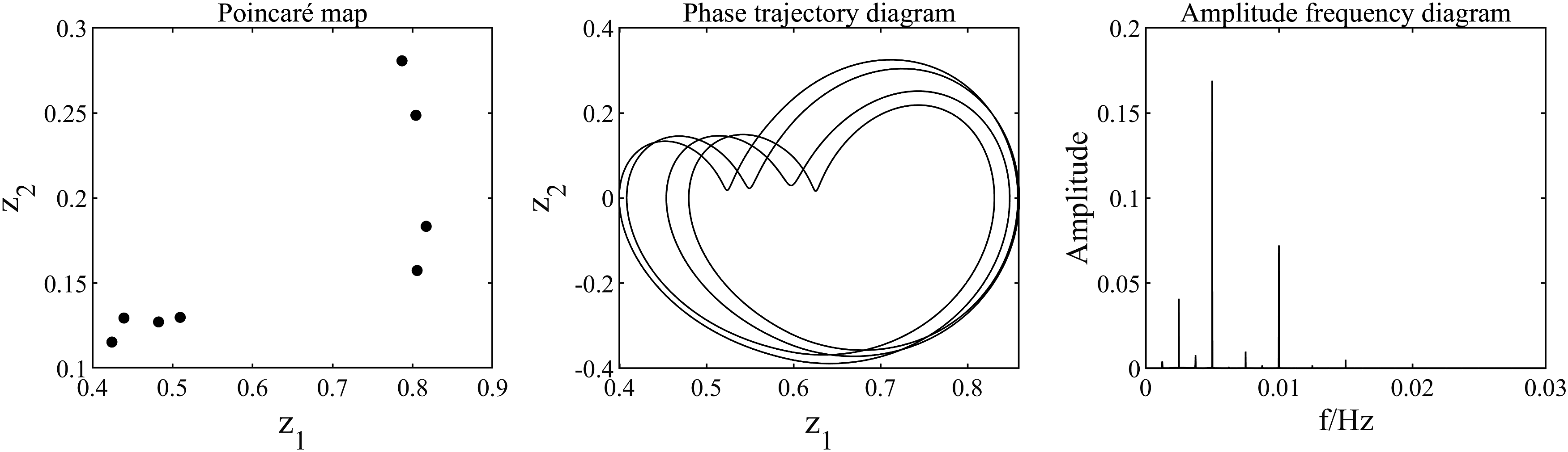
Nonlinear dynamic analysis of system under variable torque conditions
Taking the input torque Bifurcation diagram and LLE diagram of the system under variable torque condition.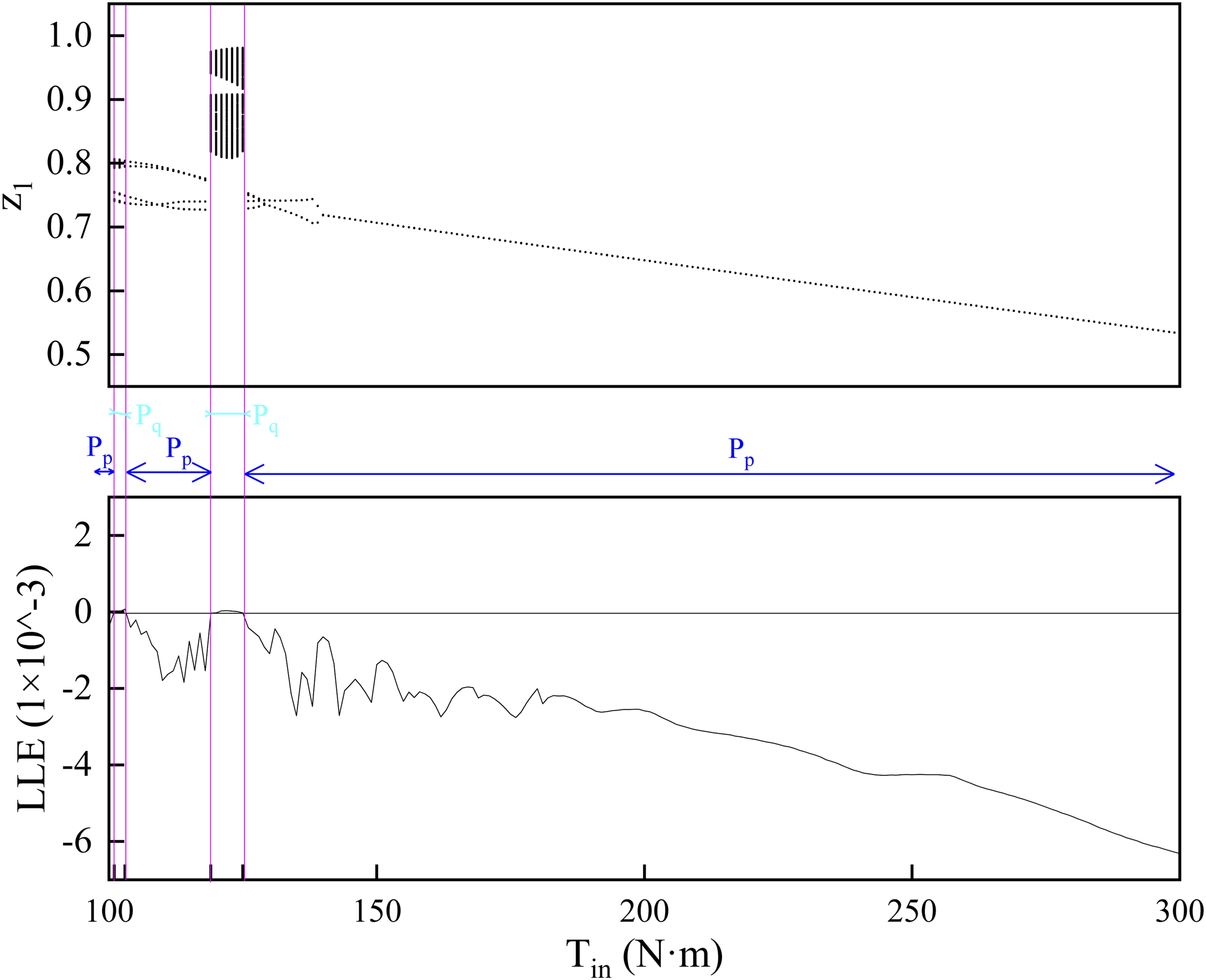
When P4 motion state of the system when 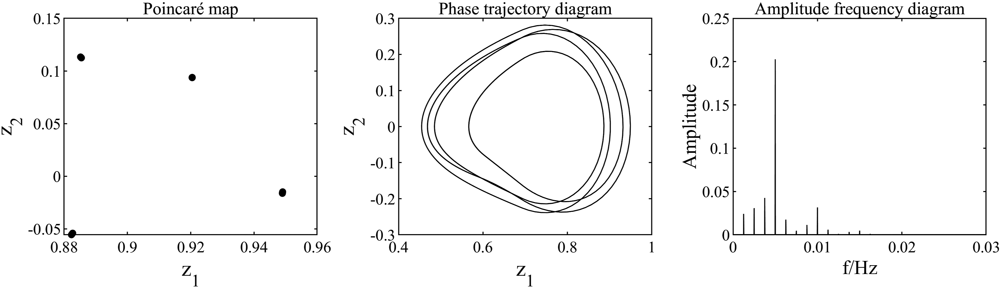
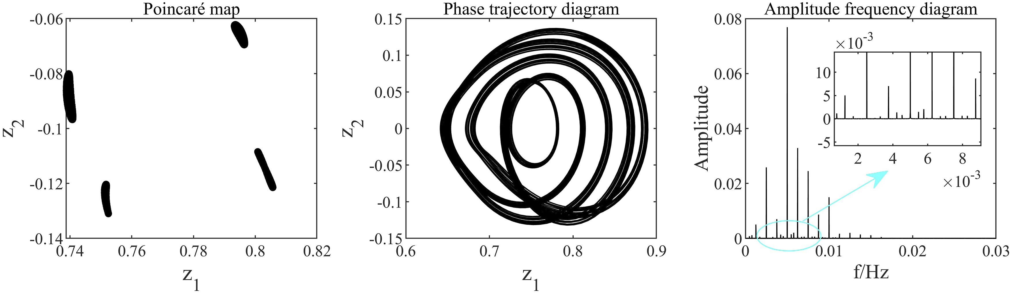
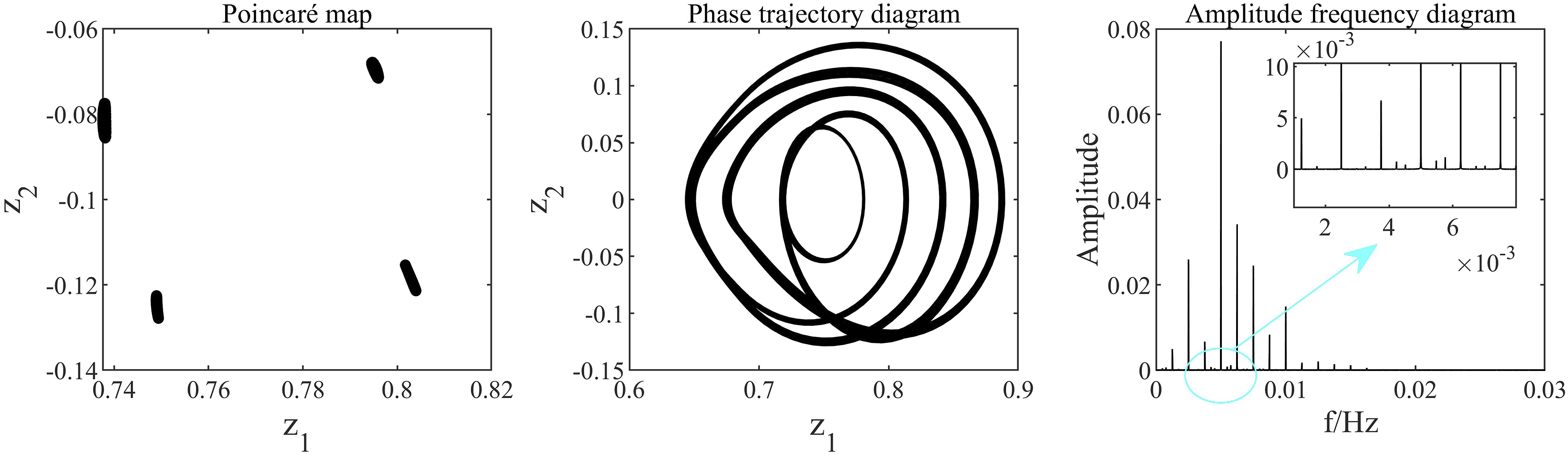
The system exhibits quasi-periodic motion when Quasi-P4 motion state of the system when Quasi-P4 motion state of the system when Quasi-P4 motion state of the system when 
The system exhibits periodic motion when P4 motion state of the system when 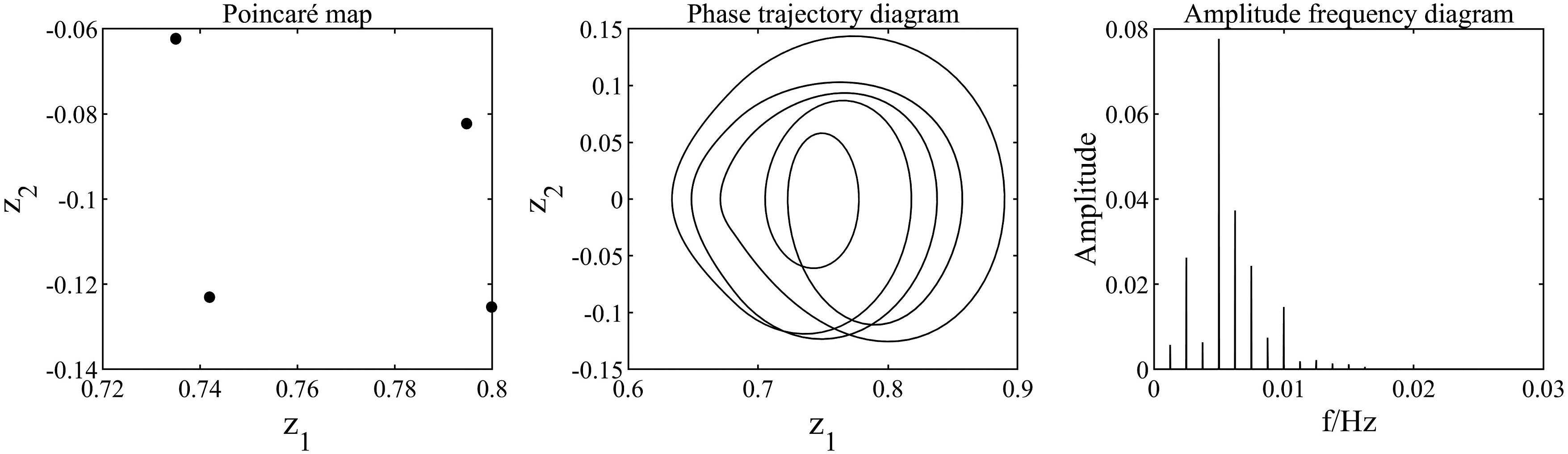
When Quasi-P2 motion state of the system when 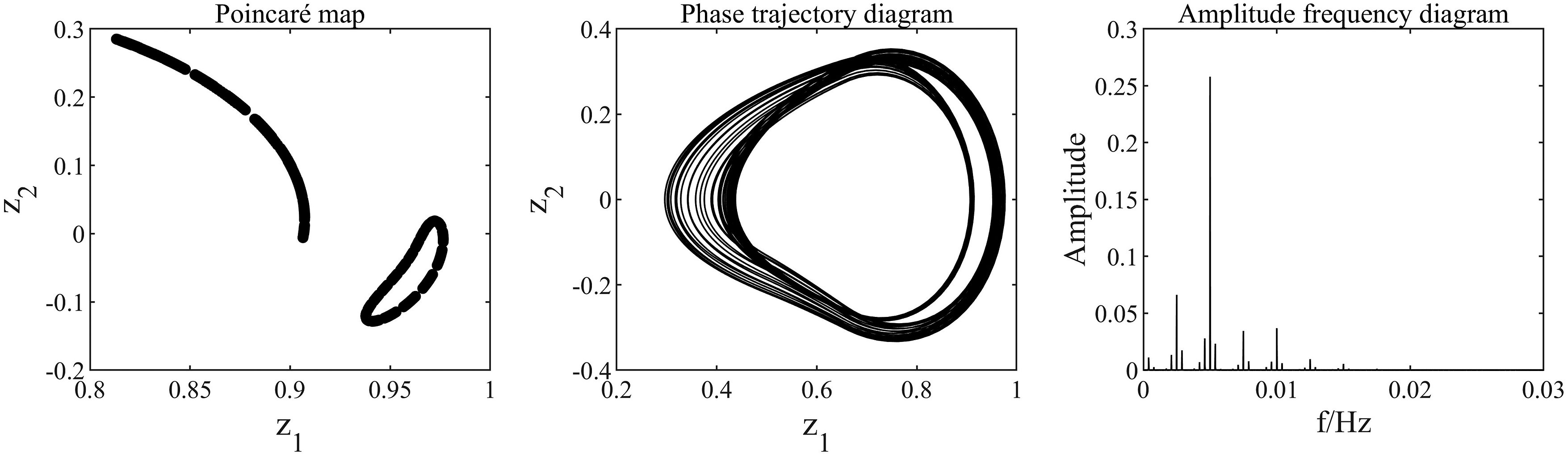
When P4 motion state of the system when P2 motion state of the system when P1 motion state of the system when 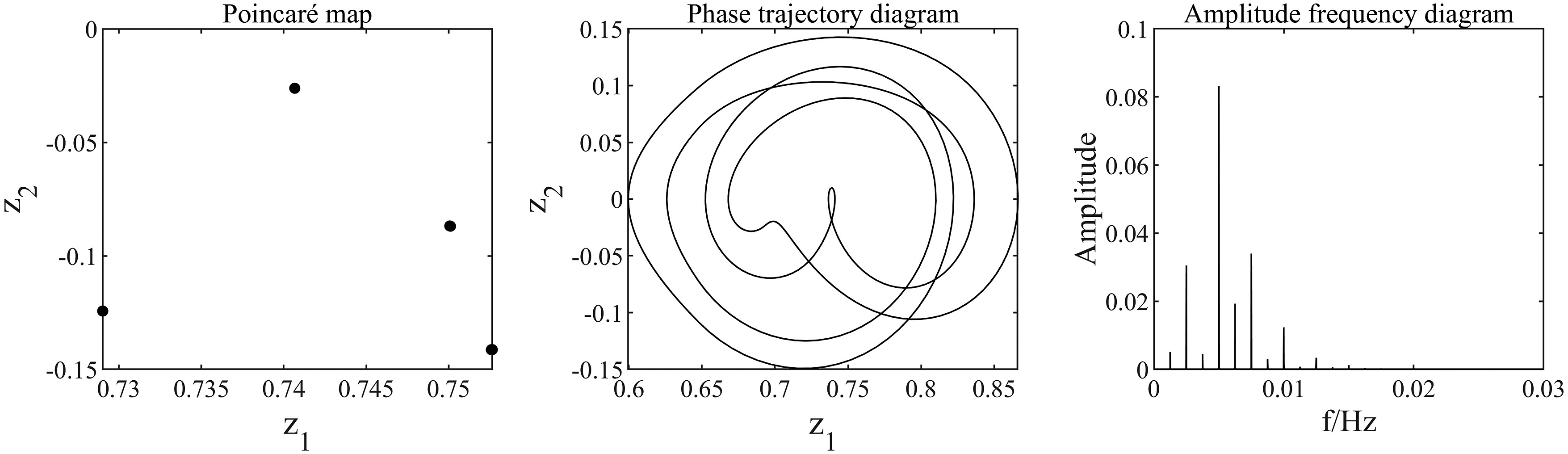
Analysis of the influence of thermal deformation on the system under variable torque conditions
Influence on the meshing impact state of the tooth surface
The original system undergoes a transition from a unidirectional impact state to a no-impact state when Phase trajectory diagram of the original system when 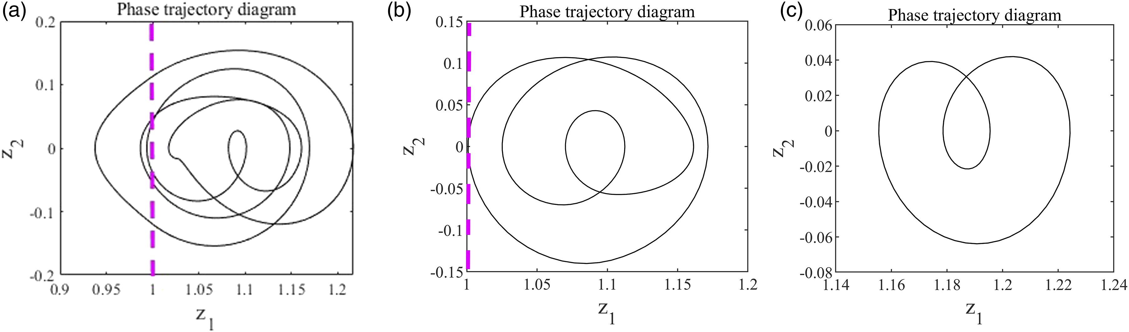
By selecting the thermal system with Phase trajectory diagram of the thermal system when 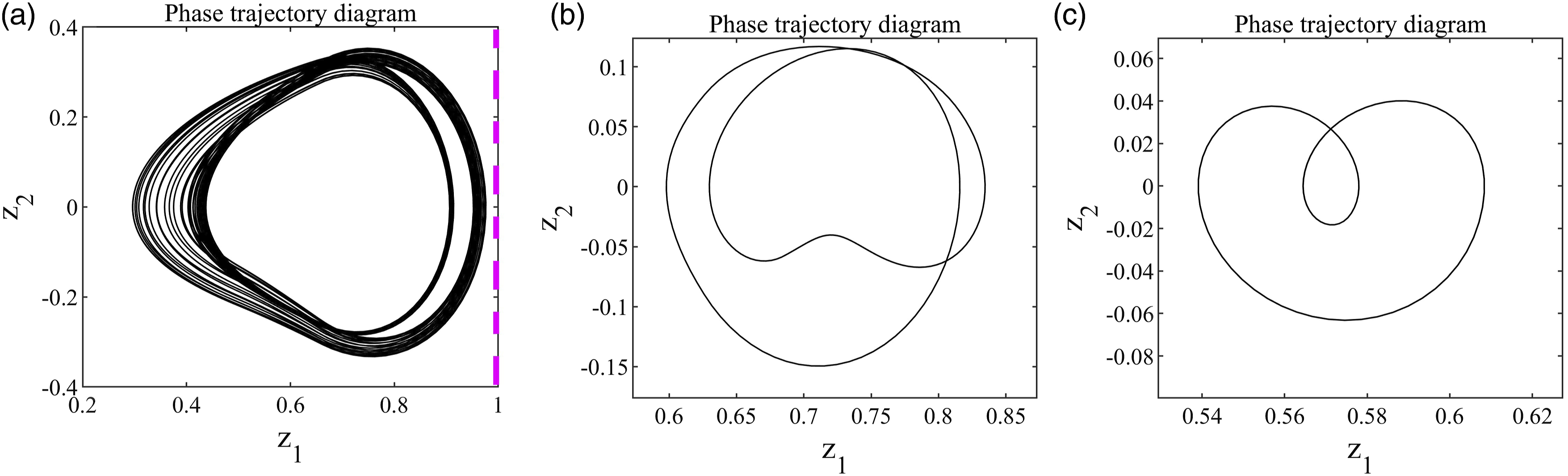
Influence on the motion state of the system
When Multi-period motion state of the original system when 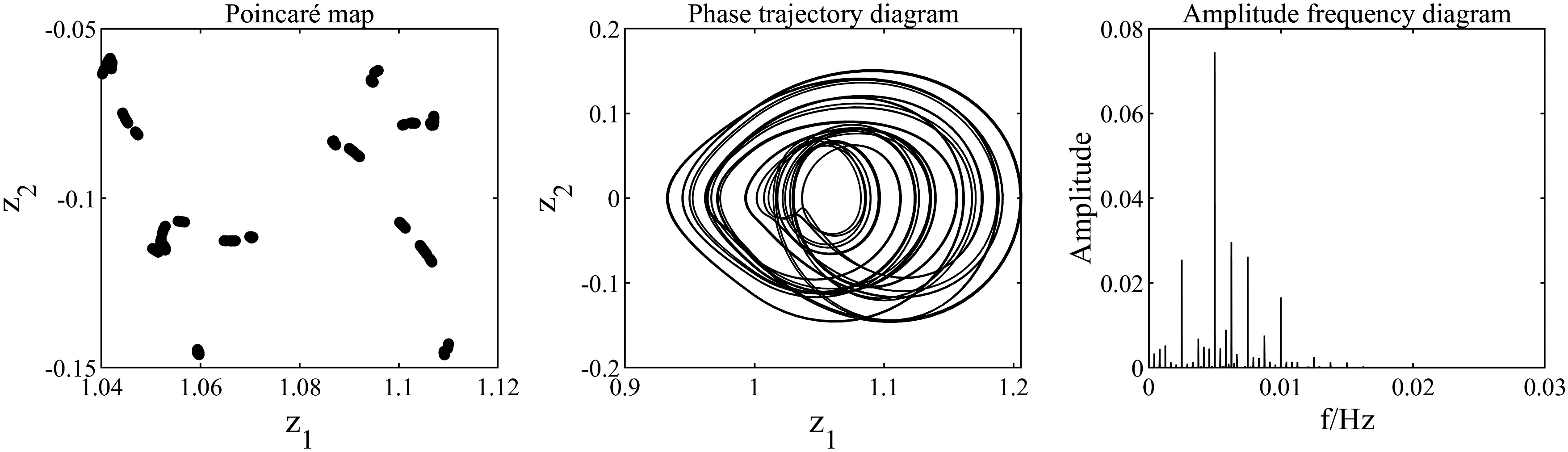
When P12 motion state of the original system when 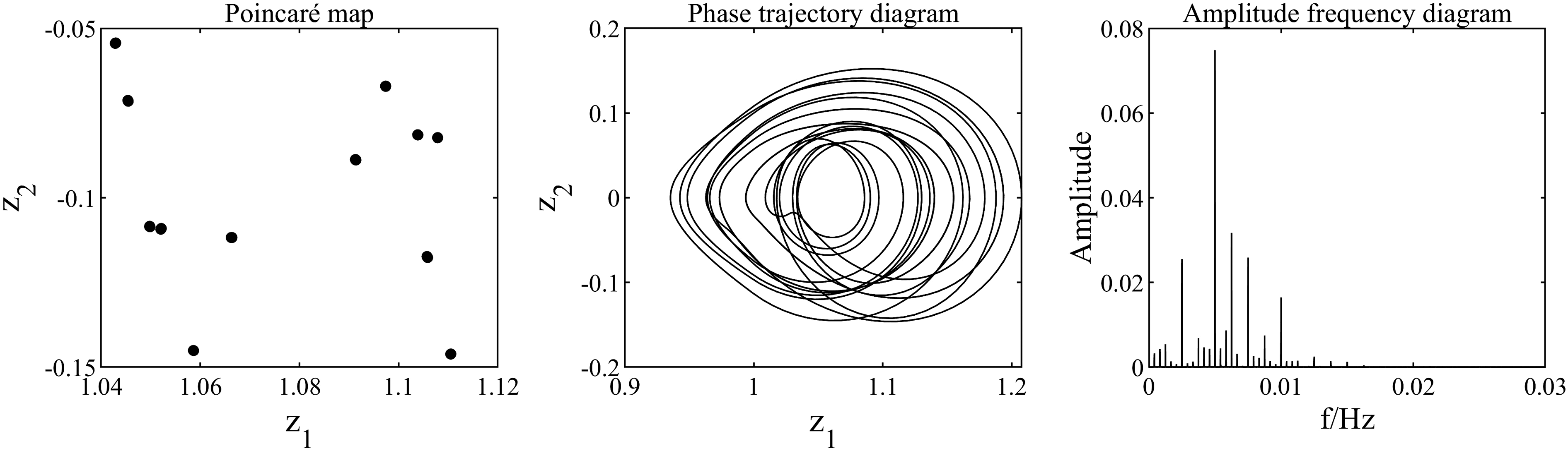
The thermal system undergoes a P4 motion, as depicted in Figure 54, when P4 motion state of the thermal system when Quasi-P4 motion state of the original system when 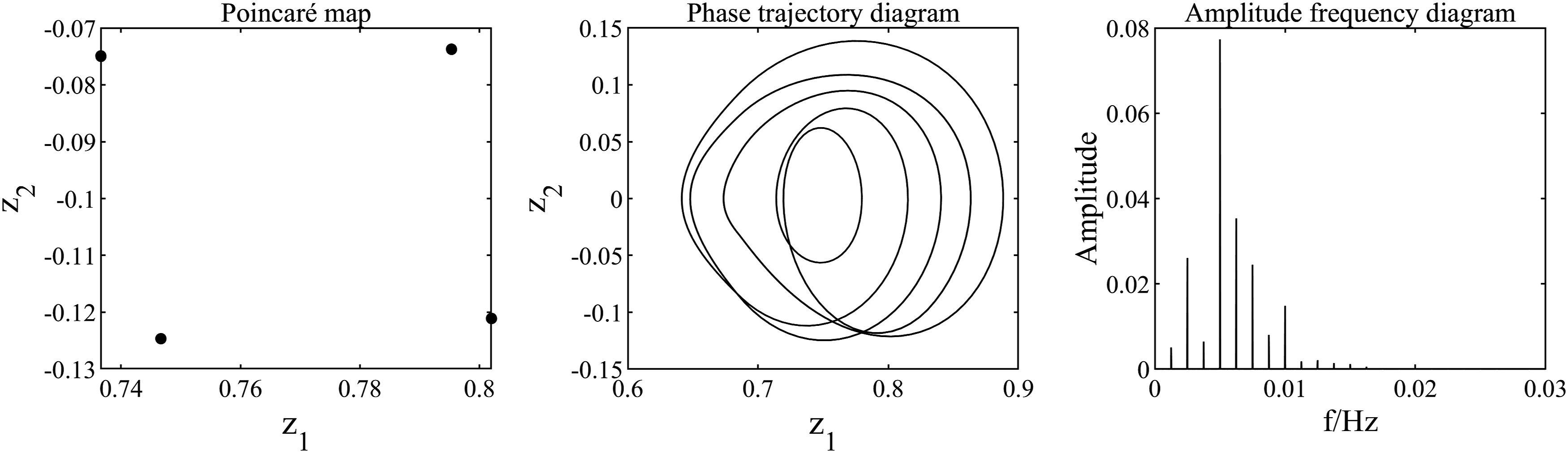
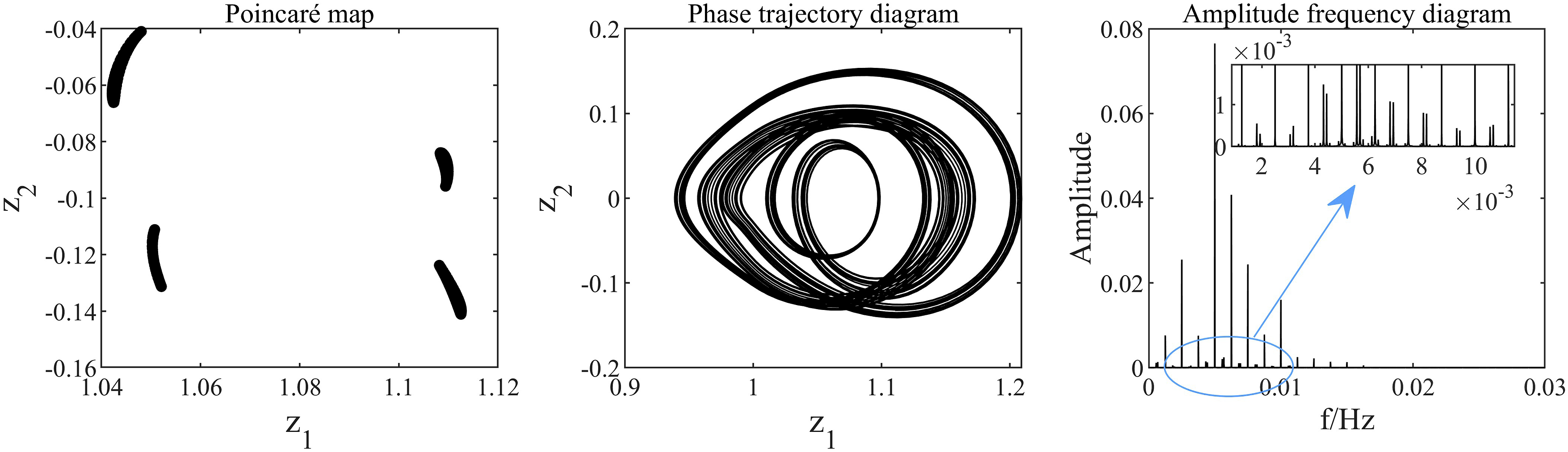
The thermal system exhibits quasi-P2 motion, as depicted in Figure 46, when P4 motion state of the original system when 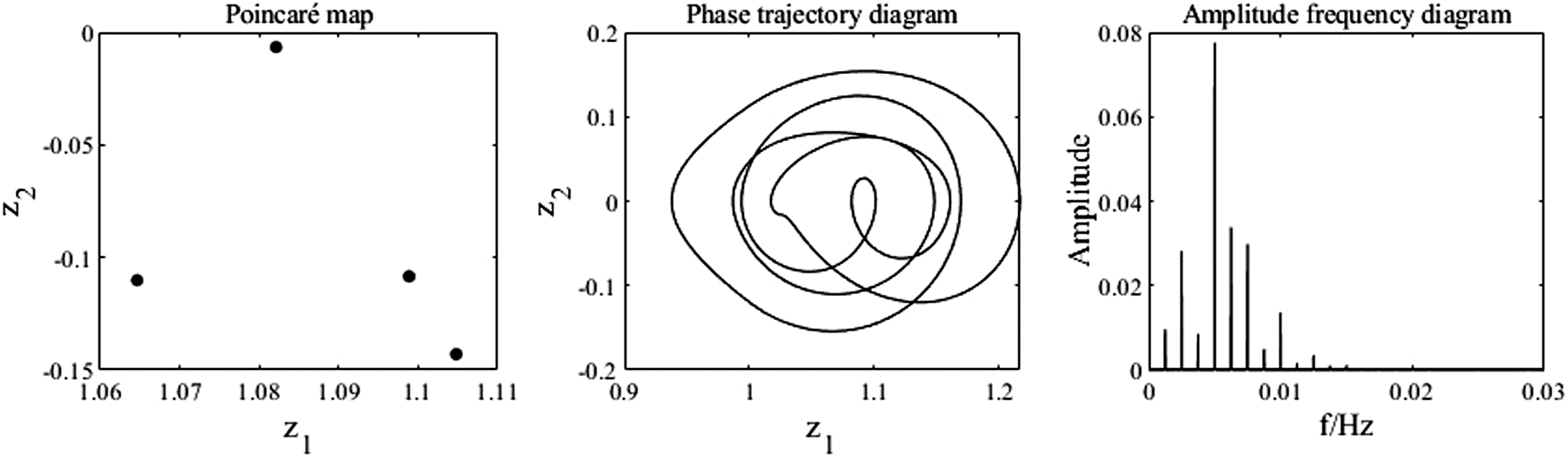
When P2 motion state of the original system when 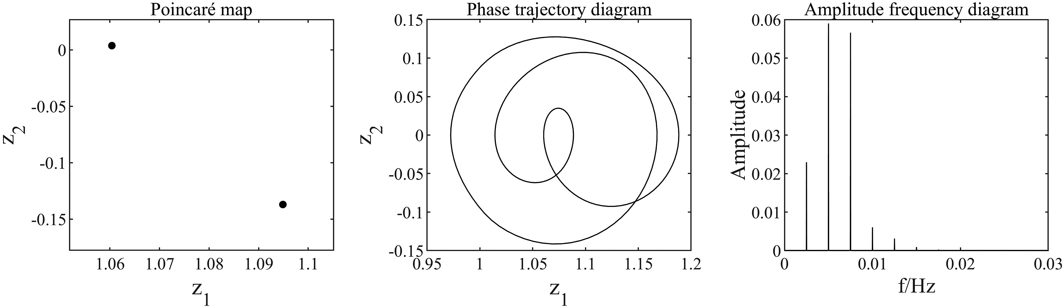
Conclusion
1. In a planetary gear system where the sun gear serves as the input component and the planet carrier acts as the output component, there is a gradual decrease in temperatures observed for the sun gear, planet gears, and ring gear. Under variable speed conditions, an increase in speed logarithmically raises temperatures across different parts of each component. Similarly, under variable torque conditions, an increase in torque linearly elevates temperatures across different parts of each component. 2. Under variable speed conditions, with an increasing meshing frequency (speed), the planetary gear system exhibits periodic motion initially followed by quasi-periodic motion and chaotic motion states with transitions between these types of motions. Thermal deformation affects nonlinear dynamics characteristics of the system in two ways: (1) It can change meshing contact from non-impact to unilateral impact state impact state which deteriorates meshing impact condition; (2) The influence of thermal deformation on system motion states is more pronounced in high meshing frequency region (high temperature region) compared to low meshing frequency region (medium-low temperature region). This leads to higher multiple-periodic motions degrading into lower multiples and quasi-periodic motions transitioning into periodic motions. Additionally, thermal deformation delays entry into chaos zone while advancing exit from chaos zone thereby shortening chaotic interval of the system. 3. Under variable torque conditions, the system exhibits periodic and quasi-periodic motion states as the torque increases. Thermal deformation also impacts the system in two ways: (1) It transforms the meshing tooth surfaces from a non-impact state to a unilateral impact state impact state, thereby deteriorating the meshing impact condition; (2) The influence of thermal deformation on the system’s motion state is more pronounced in the low torque region (medium-low temperature region) compared to the high torque region (high torque region). Thermal deformation causes degradation of multi-periodic motion into low-periodic motion, but there is also an occurrence where periodic motion of the system deteriorates into quasi-periodic motion.
Footnotes
Declaration of conflicting interests
The author(s) declared no potential conflicts of interest with respect to the research, authorship, and/or publication of this article.
Funding
The author(s) disclosed receipt of the following financial support for the research, authorship, and/or publication of this article: The authors gratefully acknowledge the support of project funded by the State Key Laboratory of Traction Power (TPL2310), Liaoning BaiQianWan Talents Program (2020921031), Natural Science Foundation of Liaoning Province of China (2020-MS-216).