
Abstract
Hunting stability is an inherent property of railway vehicles that determines the operational speed. This paper establishes a half-vehicle model with nonlinear wheel/rail equivalent conicity and interactive forces. Additionally, the dynamic performances of vehicle under various levels of wheel wear with passive suspension are compared and analyzed. Importantly, the investigation delves into the hunting stability of the vehicle system, employing both linear and nonlinear control approaches. The results demonstrate a notable reduction in critical speed during the end-worn period with a passive suspension. However, this reduction can be substantially countered through the application of active control, resulting in a significant speed increase. The implementation of stiffness control raises the frequency of limit cycles, whereas damping control serves to diminish it. Notably, an appropriate linear cubic stiffness control effectively mitigates the amplitudes of limit cycles during instances of instability. Moreover, the control strategy derived from the simplified model is extended to enhance the stability of the entire vehicle system. The research findings hold the potential to offer a promising strategy for the active control of high-speed vehicles, particularly during periods of wheel wear.
Introduction
High-speed and safety are the eternal pursuit of railway vehicles. Hunting stability, as the basis of vehicle dynamic performances, directly determines the maximum running speed of vehicles, which is of great significance to the vehicle system.
1
Hunting instability will cause the vehicle to vibrate violently, worsen the riding comfort, intensify the wheel/rail interactive forces, damage the structural components, and even threaten the derailment safety.2–4 With the mass popularization of high-speed trains and the sharp increase in operating mileage, the contradiction between wheel/rail wear and suspension system parameters has become increasingly prominent, resulting in more and more troubles concerned with hunting stability of vehicle system.5–7 According to the existing field test data from the project team in Southwest Jiaotong University, a certain type of high-speed train named CRH380 B experienced a high-frequency bogie hunting motion above 7 Hz during the service process at end-worn wheel period, as shown in Figure 1, where the blue zone indicates a stable state while the red zone suggests a bogie hunting motion, with its hunting frequency in 7.8 Hz. Generally, the drastic bogie hunting motion will cause lateral acceleration alarm and trigger the vehicle slow down or stop, which seriously affects the normal operation order of the train. On top of that, if the bogie hunting frequency is close to the modal frequency of carbody, the shaking phenomenon will occur, degenerating the riding comfort.
8
Hunting motion in field test.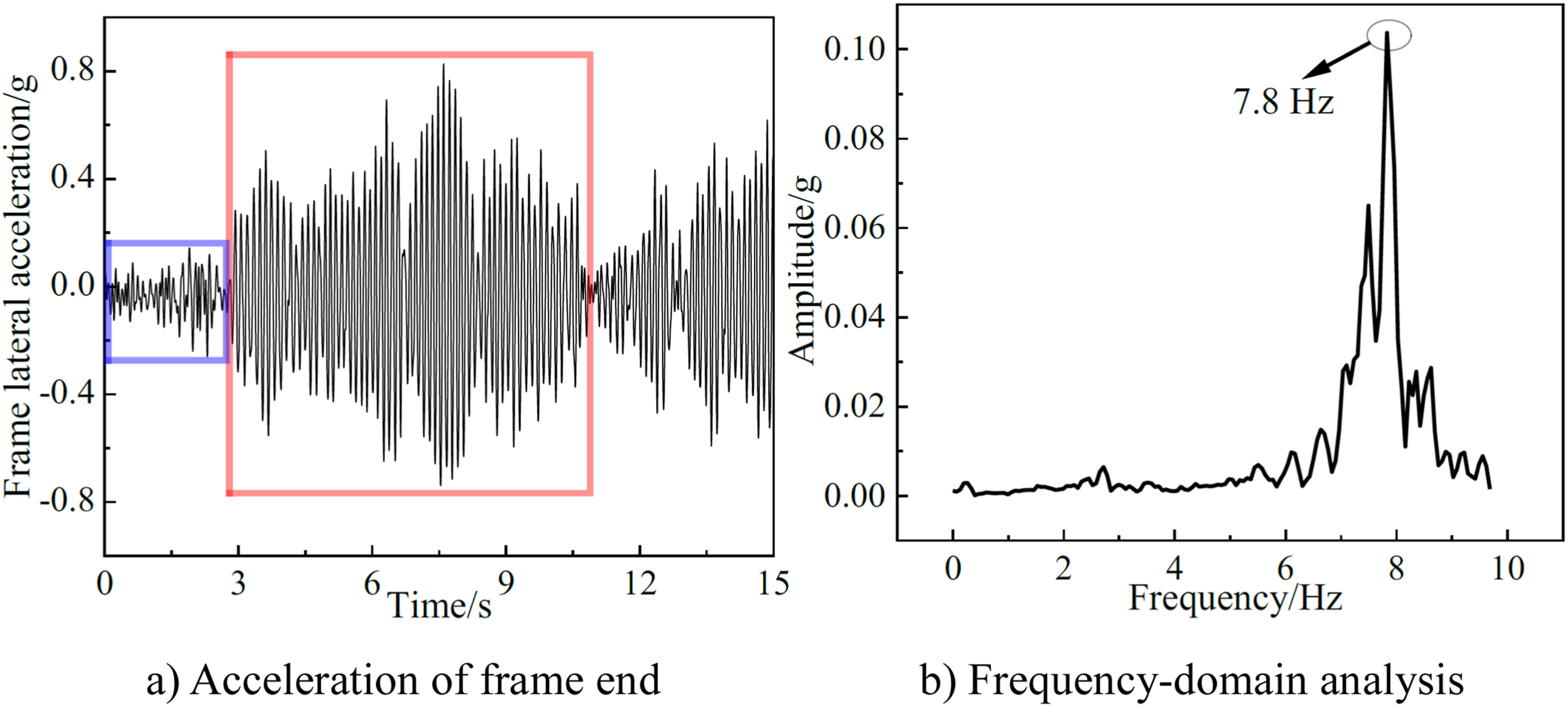
Over the past decades, hunting stability has been a hot issue of vehicle dynamics research by scholars. Wagner conducted simulation analysis on a nonlinear railway wheelset, showing the subcritical Hopf bifurcation features and limit cycles, in which the possibility of unstable limit cycles was studied in detail. 9 Zhai and Wang established a vehicle-track coupled model for the vehicle system, proposing an effective algorithm to attain the critical speed, where the influences of dynamic properties of track were considered. 10 Polach and Kaiser made a comparison between path-following method and brute-force method to distinguish hunting behaviour and bifurcation of railway passenger car, and results demonstrate that both of them match well with each other, which is reliable. 11 Bustos et al. studied the vehicle’s stability by means of root loci methods, both stable and unstable regions and the existence of limit cycles was discussed. 12 Cheng and Lee deduced the motion differential equation of a half-car system, where the effects of different physical parameters and the discrepancy of conicity on critical hunting speeds were investigated. 13 Bigoni et al. analysed the sensitivity of the critical speed to suspension parameters and demonstrated that the accuracy of determining the parameters is crucial and universal. 14 Chen et al. utilized a multi-objective optimization method to coordinate the contradiction on suspension parameters at high and low wheel/rail contact conicity conditions, and they defined equivalent conicity robustness as the key optimal index. 15 Wei and Yabuno carried out bench test with a roller rig to investigate the function of quintic nonlinearity to hunting stability, proving that cubic and quintic nonlinearity can make a difference to subcritical Hopf and saddle-node bifurcations of the vehicle system. 16 Zeng et al. introduced a new index to describe the cyclicity of state variable series and made a proposal that the hunting motion alarm and stability assessment can be achieved in space and time domains. 17
To ensure an adequate stability margin against hunting motion, the conventional approach involves optimizing the passive suspension parameters and the wheel/rail relationship within the vehicle. Alternatively, employing active control not only enhances stability significantly but also considers the adaptability to complex environments. In terms of active control, Zeng et al. combined numerical simulation with rig test to acquire the Hopf bifurcation point and limit cycles of the vehicle system, then a H-infinity robustness control theory was adopted to design an actively controlled secondary lateral suspension, illustrating that active secondary suspension is of great use to dynamic responses of vehicles. 18 Bruni and Huang discussed the current concept, method and engineering application of active control of railway vehicles, and proposed promising application trends for active control.19,20 Yabuno proposed nonlinear control methods in hunting motion of railway wheelset theoretically and experimentally, where an underactuated manipulator without actuators was used to perform action. 21 Yao et al. conducted simulation and experimental study through a simplified bogie model on active hunting stability control based on lateral vibration of frame, with the time-delay of control actuator considered, and the results indicate that the three control schemes can effectively improve hunting stability of vehicles, while the adaptation conditions are different.22–25 Abood and Khan carried out a semi-active control study on the longitudinal primary stiffness suspension, and results show that the critical speed of the bogie system can be improved and the hunting instability can be avoided. 26 Zhu et al. combined active secondary with primary suspensions to improve the ride quality and hunting stability simultaneously of a full-vehicle system, using the linear-quadratic-Gaussian (LQG) control theory. 27
In summary, scholars have carried out extensive and detailed researches on hunting stability analysis in railway vehicles under traditional passive suspension. However, few studies have been reported on the bifurcation characteristics of hunting motion in the context of parameter degradation and active control. Consequently, it is crucial to delve into several aspects: comparing the bifurcation characteristics between passive and active control systems, determining whether the active control can increase the Hopf bifurcation point (improve the critical speed of vehicle), managing the amplitude of limit cycles after instability, adjusting the hunting frequency to avoid resonance, and exploring the stability evolution law when using active control are worthy of being studied in-depth.
In this paper, a 3-DOF (Degrees of freedom) half-vehicle model of a high-speed vehicle considering nonlinear wheel/rail interactive forces and yaw damper forces is established, where the wheel profiles at each worn stage are acquired by field test and transformed to its nonlinear wheel/rail equivalent conicity relationship, which can be utilized to calculate the critical speed and limit cycle of vehicle system. Moreover, the yaw motion of frame is used as the control force to the vehicle system. As a result, the hunting stability of the vehicle system under linear and nonlinear active control has been investigated in detail. Furthermore, a full-vehicle model is established to compare and verify the feasibility of the simplified model control strategy.
Mathematical model
Simplified vehicle model
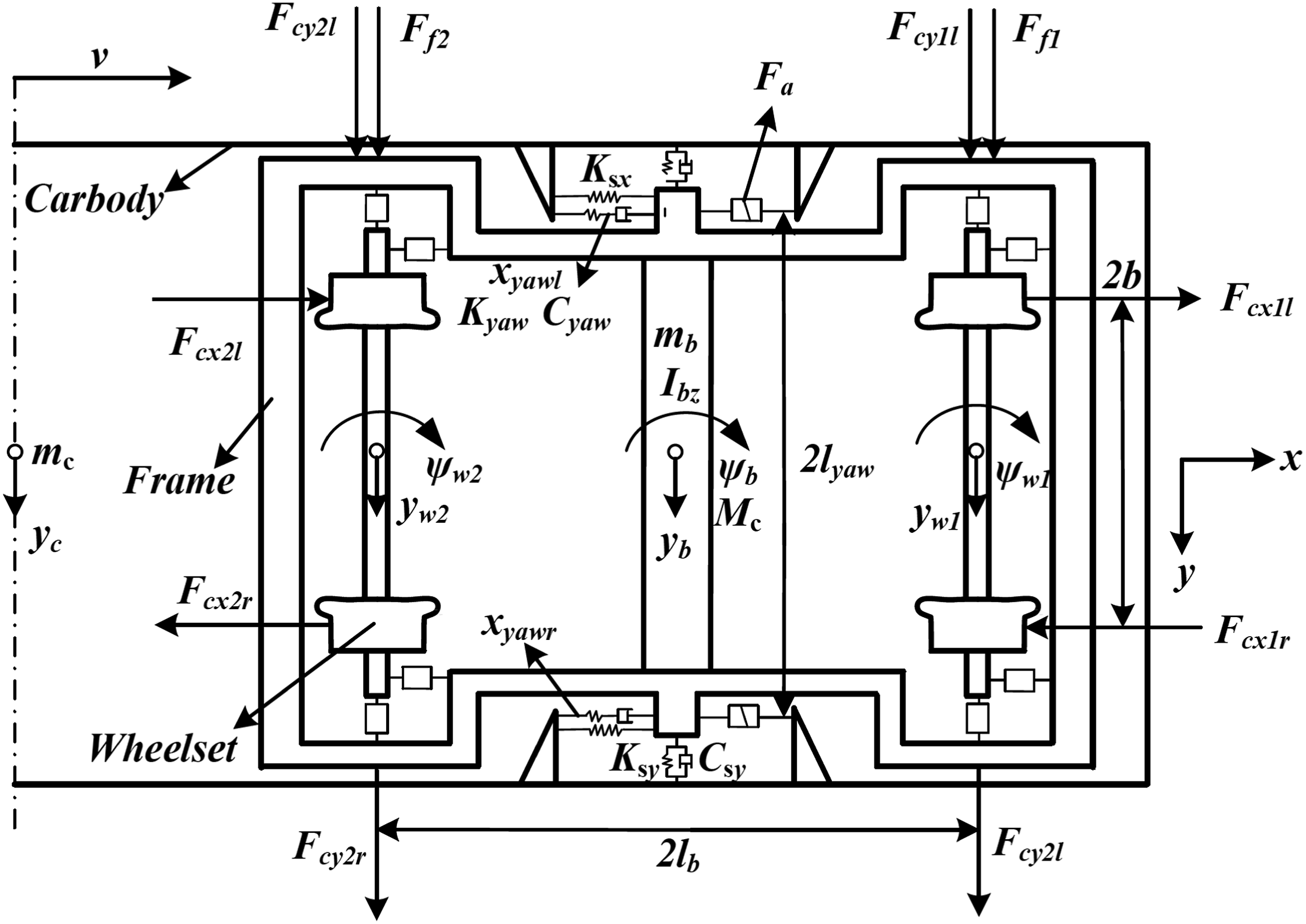
This paper mainly analyses the hunting stability of vehicle system, belonging to vehicle lateral dynamics, so the vertical and longitudinal degrees of freedom are not included. Meanwhile, the influences of secondary suspension need to be considered to implement active yaw damper forces. As a consequence, a simplified 3-DOF half-vehicle is adopted as shown in Figure 2, in which the lateral displacement of bogie frame/carbody and yaw motion of frame are considered. The half-vehicle system is deemed to be a multi-rigid-body system consisted of front carbody and bogie frame, where the secondary suspensions are installed to link them. Below are the fundamental assumptions of the model: (1) The connection between frame and wheelsets are rigid, with the primary positioning stiffness infinite, and the creep forces act directly on the frame, ignoring the spin effect of wheelset. (2) The vehicle runs on a smooth straight track, regardless of the impact of track irregularities. (3) The wheel/rail geometric relationship at end-worn wheel period through field test is considered as a nonlinear function of wheelset lateral displacement to calculate Hopf bifurcation of the vehicle system. (4) When in the passive suspension condition, the traditional yaw dampers in Maxwell model
28
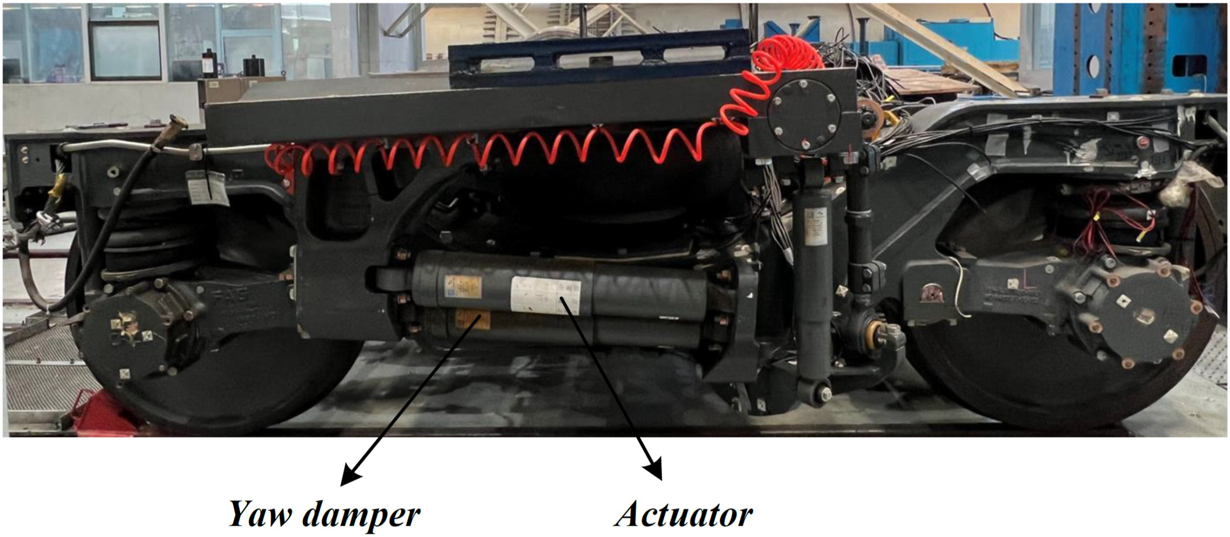
are redundantly connected in parallel, while under the active suspension state, one of the yaw dampers on left and right sides is, respectively, replaced with an active actuator, as shown in Figure 3. Simplified vehicle model. High-speed bogie.
DOF of the simplified vehicle system.
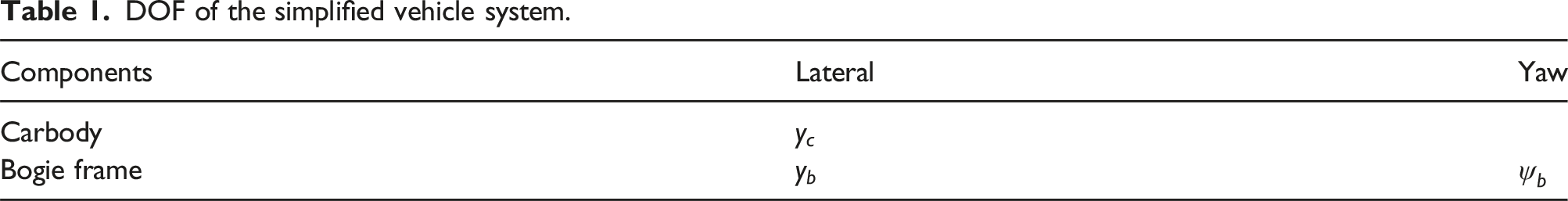
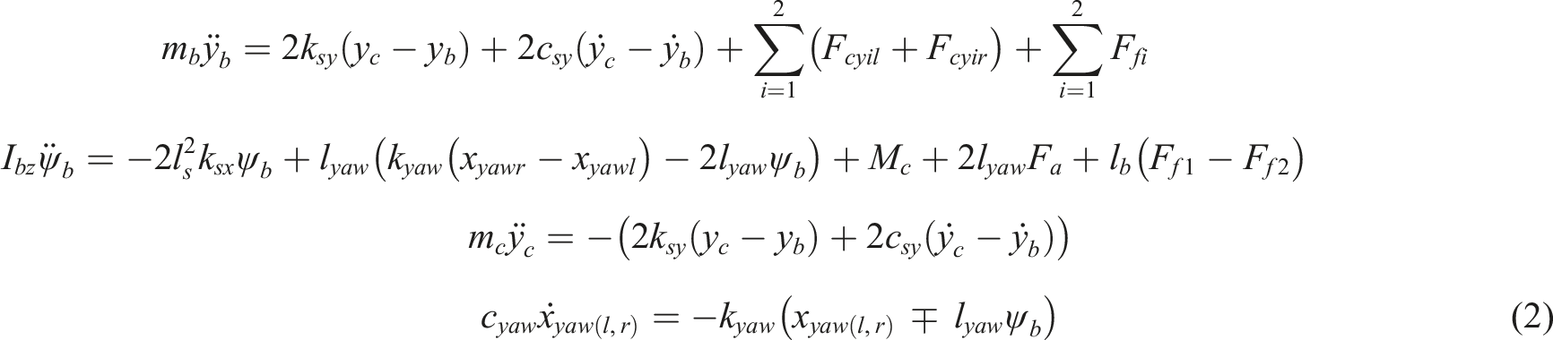
Based on the hypothesis of a rigid bogie, the yaw motions of wheelsets (i = 1 and 2, meaning the front and rear wheelset, l and r showing the left and right side) and frame are identical, while the relationship of its lateral displacement presented in equation (1)
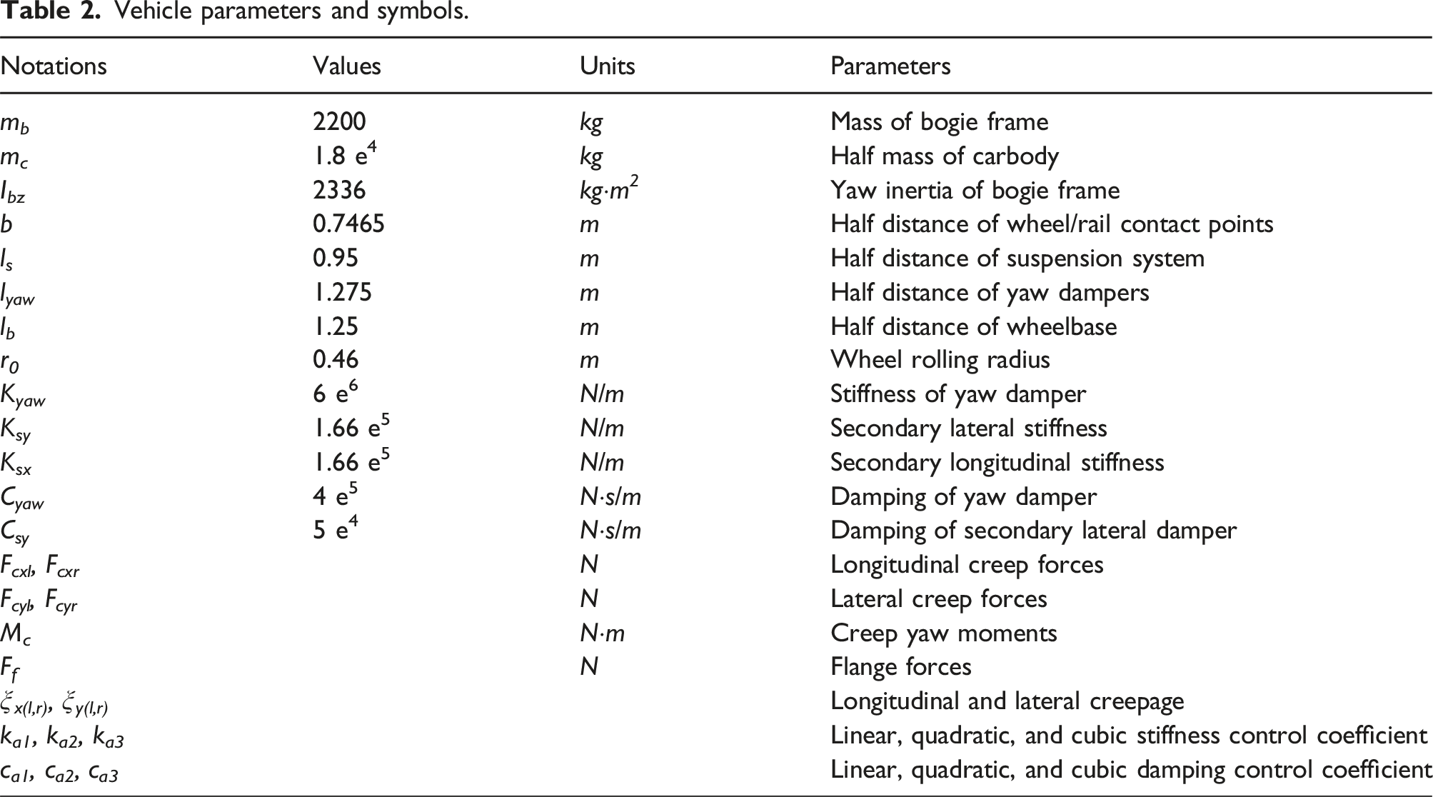
Vehicle parameters and symbols.
Wheel/rail contact geometry relationship
The wheel/rail contact geometry relationship is decisive to interactive forces between wheels and rails. Figure 4 shows the typical wheel/rail geometry parameters. The lateral displacement (y
w
) is defined as movement of the wheelset relative to track centre due to its conicity. The rest of parameters including contact angle (δ
l
, δ
r
), roll angle (ϕ
w
), rolling radius (r
l
, r
r
), and wheel profile curvature radius (Rw
l
, Rw
r
) can be viewed as nonlinear functions of y
w
. Wheel/rail contact geometry parameter.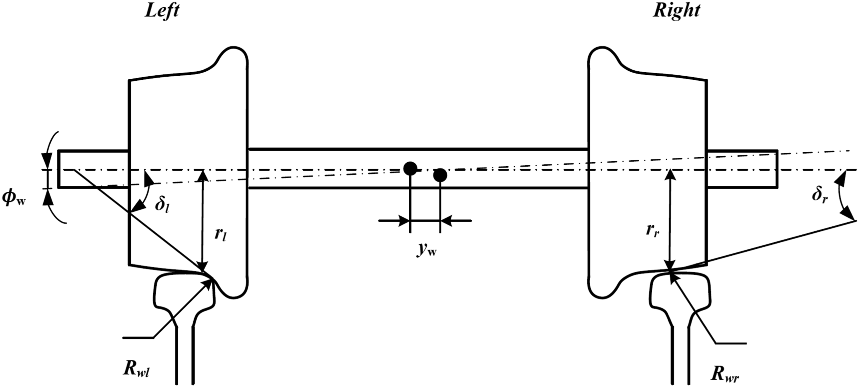
Once the wheel/rail contact point is confirmed, its geometric parameters will also be uniquely determined. However, the wheel profile is altering with the increase of operating mileage, leading to wheel wear, which causes time-varying wheel/rail relationship. Usually, the equivalent conicity
29
λ(defined as the tangent of the cone angle of a wheelset with coned wheels whose lateral movement has the same kinematic wavelength as the given wheelset) is used to evaluate the wheel/rail contact geometry simply and reasonably. The actual wheel profiles at different worn periods of a representative high-speed vehicle measured in field test is displayed in Figure 5, where the new, mid-worn, and end-worn wheel correspond to 0/100,000/250,000 km operating mileages, respectively, and it gives the relationship between equivalent conicity and wheelset lateral displacement. Wheel/rail contact relationship.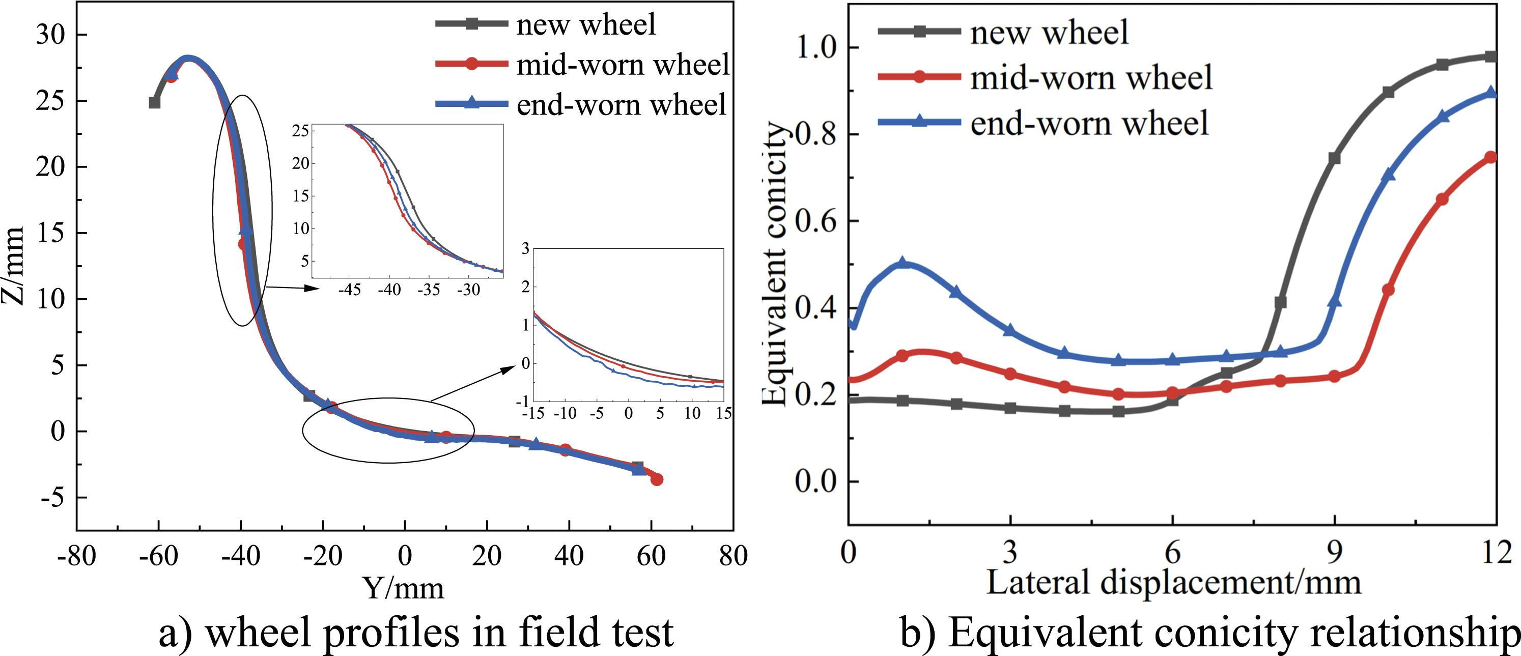
It is clear from Figure 5 that differences between the vertical and lateral distances of wheel tread profiles at three stages are diminutive, while the equivalent conicity at end-worn stage is significantly larger than that of the new and mid-worn period, which can deteriorate the dynamic performance of vehicle system. Consequently, the relationship between λ and y
w
at end-worn period can be derived as a nonlinear function in equation (3) and applied to hunting stability analysis of the vehicle system
Wheel/rail interactive forces
The nonlinear wheel/rail creeping forces will formulate once the wheel rolls on the rail, causing a relative slip in wheel/rail contact zone. Every single wheel is subjected to longitudinal, lateral creep forces, and spin creep moments, which can be calculated from the longitudinal and lateral creepages (ξ
x
, ξ
y
) of the left and right wheel as given in equation (4)
With the purpose of calculating creep forces, the Kalker’s linear creep theory
30
is harnessed. Since the spin effect of wheelset is neglected, the expressions of longitudinal/lateral forces (F
cx
/F
cy
) can be derived as equation (5)

As a consequence, the creep yaw moment (M
c
) of vehicle system can be expressed as equation (7)
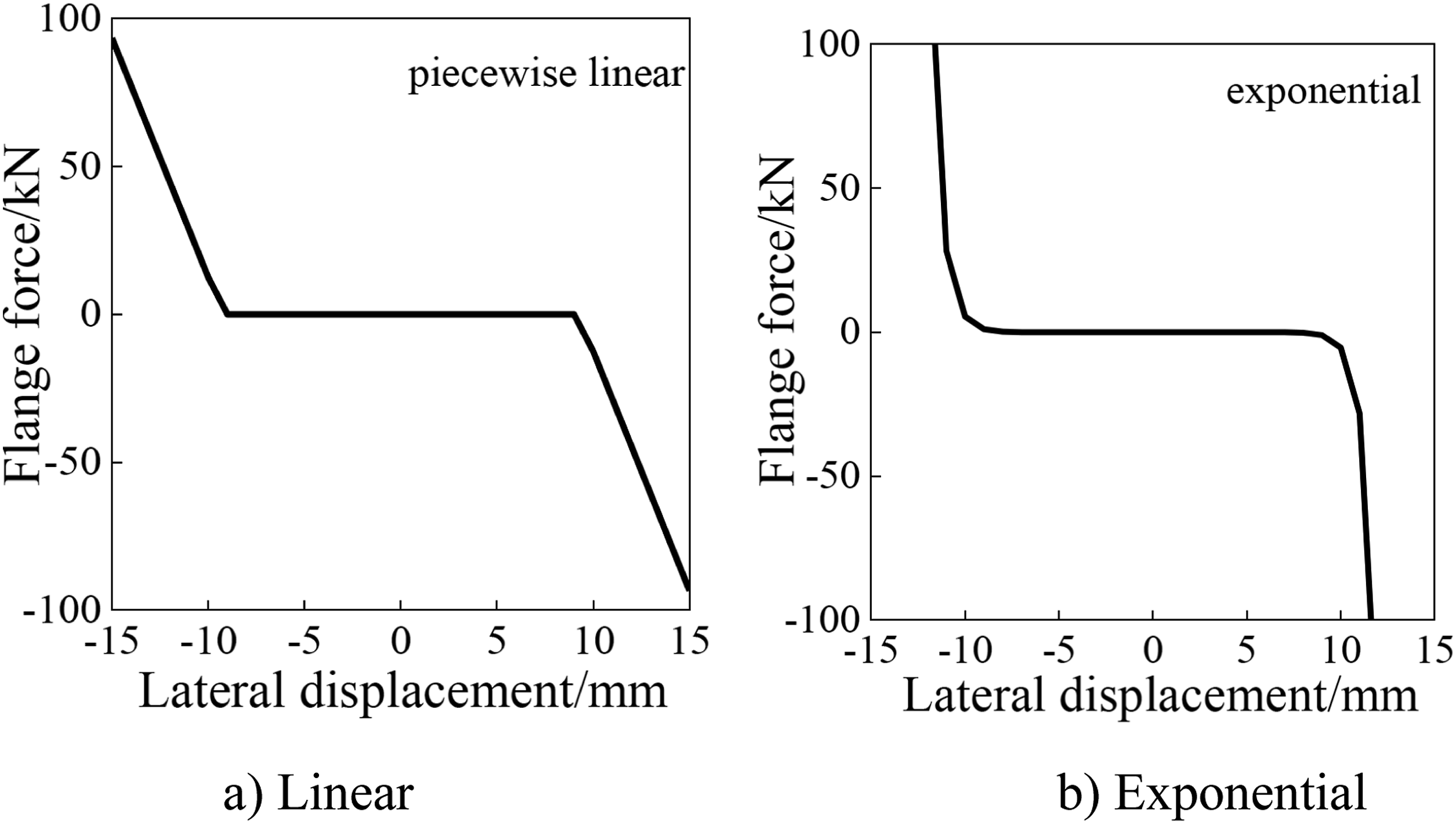
When the vehicle speed exceeds the Hopf bifurcation point, the hunting motion will diverge, and for this reason, the limiting effect of flange forces needs to be considered. The flange forces in the traditional dynamic calculation are represented by a piecewise linear function, while a detailed comparison of different flange force models was conducted in Ref. [3] so the exponential model form of flange forces (F
fi
) is adopted as shown in equation (8), followed by its fitting diagram in Figure 6 Comparison between flange force models.
3

Active yaw damper control forces
Given that the control method in this paper is to replace one of the yaw dampers of traditional high-speed vehicle with an actuator to realize active control, the control force should have stiffness and damping characteristics. Furthermore, the linear and nonlinear effects of control forces on the vehicle system can also be considered. Therefore, the control force (F
a
) can be expressed as equation (9)
Motion differential equation of vehicle system
In this case, the motion differential equations of half-vehicle system on straight track can be described as equation (10) in vector form

Once the differential equation of motion is confirmed, the bifurcation diagram can be obtained through mathematical method to analyse hunting stability of the vehicle system. Firstly, it is necessary to determine the Hopf bifurcation point, which is called critical speed. 31 Then, Matcont 32 is applied to solve the limit cycle motion after Hopf bifurcation.
Hopf bifurcation in simplified vehicle model
Passive suspension
The existing high-speed trains use passive suspension systems, once the parameters are fixed, the dynamic performance of the vehicle at new wheel state reaches to the limit, which results in tremendous differences in dynamic behaviour between new and worn-wheel conditions.
Figure 7 illustrates the Hopf bifurcation diagrams of the vehicle system at end-worn wheel period. Simultaneously, the lateral vibration acceleration of the bogie frame is also calculated, where the curve in the figure represents the amplitude of the corresponding variables. It should be pointed out that the Hopf bifurcation point of the vehicle system at new and mid-worn periods is much greater than 400 km/h, so it is not drawn. Analysis with passive suspension.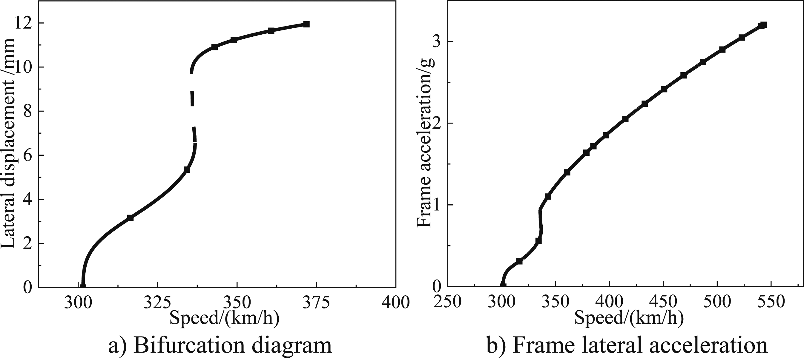
Evidently, for the high-speed vehicle with passive suspension, the Hopf bifurcation point of the system at end-worn wheel period experiences a significant reduction. This reduction signifies an inadequate hunting stability margin, categorizing it under the supercritical bifurcation type, potentially leading to the emergence of unstable limit cycles (depicted as dotted lines). Similarly, the frame lateral acceleration also magnifies after the instability happens, and as the vehicle speed reaches 350 km/h, the peak frame lateral acceleration has exceeded the alarm limit of 0.8 g, 33 which worsens riding comfort of the vehicle system. As a result, both linear and nonlinear active control forces are added to the differential equations of the system, and their effects on Hopf bifurcation of the vehicle system are investigated, respectively.
Active yaw damper with linear control
Let j in equation (9) be equal to 1 to realize linear active control, where the yaw motion of frame is used as control signal. In order to separately analyse the influence of the stiffness linear term and damping linear term on hunting stability of the vehicle system, the control variable method is adopted. Under linear stiffness and damping control, the characteristics of Hopf bifurcation diagram, hunting frequency, control forces and frame lateral acceleration are shown in Figures 8 and 9, respectively. Besides, when considering stiffness control, the linear damping coefficient is fixed at 0.25 e5. Correspondingly, the linear stiffness coefficient is 1e6 while considering damping control. Analysis under linear stiffness control. Analysis under linear damping control.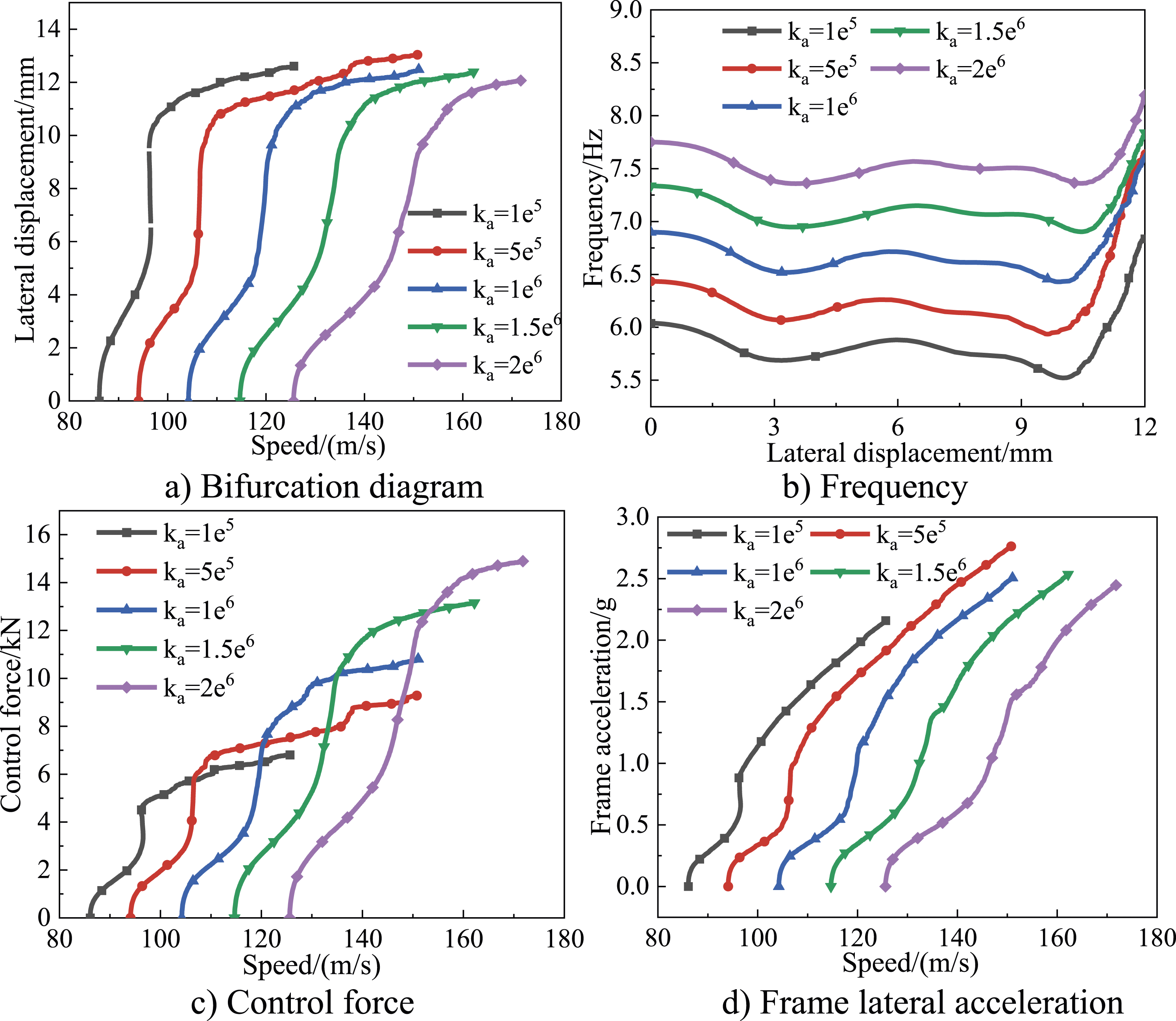
From the perspective of the bifurcation diagram in Figures 8 and 9, both linear stiffness and damping control can delay the Hopf bifurcation point.
This delay subsequently raises the critical speed of the vehicle system. Notably, the magnitude of this effect is directly proportional to the stiffness and damping levels implemented. Additionally, the impact of linear stiffness term on critical speed is more remarkable, as the gap between Hopf bifurcation point under linear stiffness control is much wider than that of linear damping control. However, the increase of the stiffness coefficient cannot reduce the amplitude of the limit cycle after bifurcation, while the damping coefficient can achieve that. With respect to hunting frequency of vehicle system, the enhancement of stiffness term will cause hunting frequency to augment, while the damping term has the opposite effect. In view of control force, it grows with the gains of stiffness and damping, but the effect of damping is much more prominent. In the context of the frame lateral acceleration, the change of the linear stiffness coefficient has little effect on the frame vibration acceleration after bifurcation, but the linear damping coefficient can lower its acceleration amplitude, which is consistent with the change law of the limit cycle.
Active yaw damper with nonlinear control
When j in equation (9) equals to 2, the nonlinear quadratic control can be achieved. Figure 10 demonstrates the bifurcation diagram and hunting frequency after the quadratic term stiffness coefficient is employed. Analysis under quadratic stiffness control.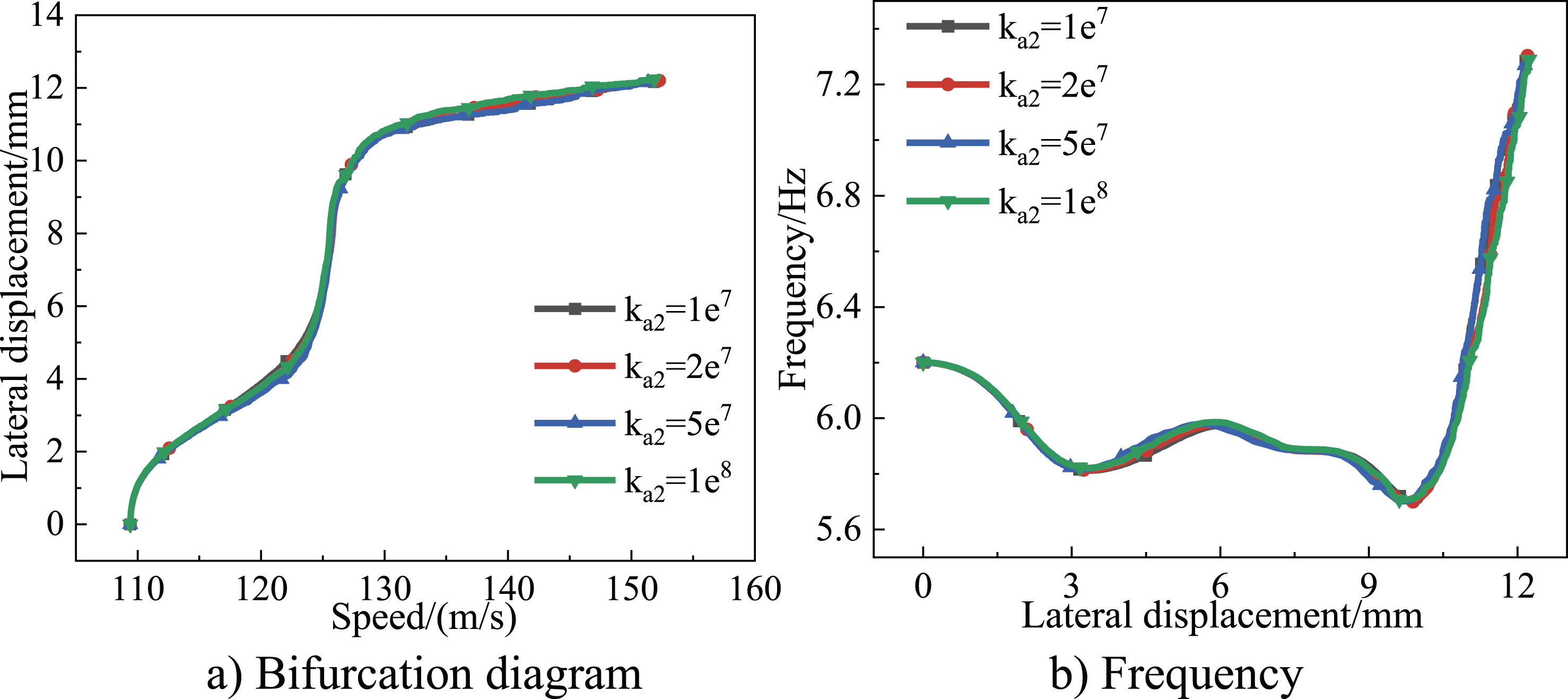
It is evident that quadratic stiffness control is noneffective on the Hopf bifurcation diagram and hunting frequency of the vehicle system, and has a similar effect on control force and frame acceleration, so it is not shown in the figure.
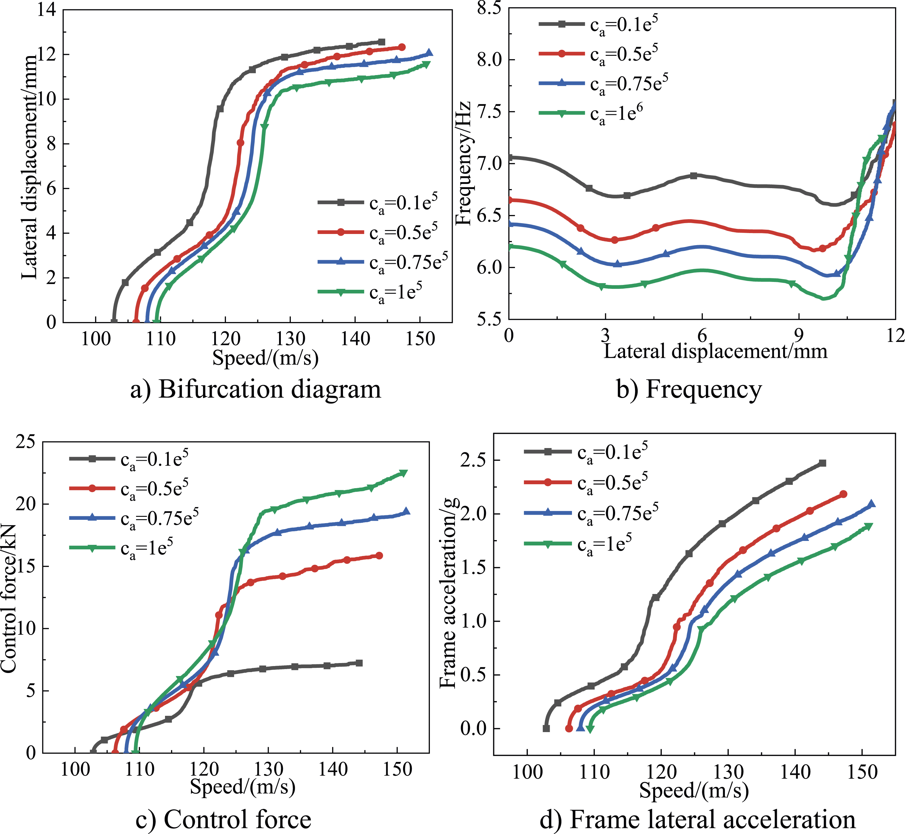
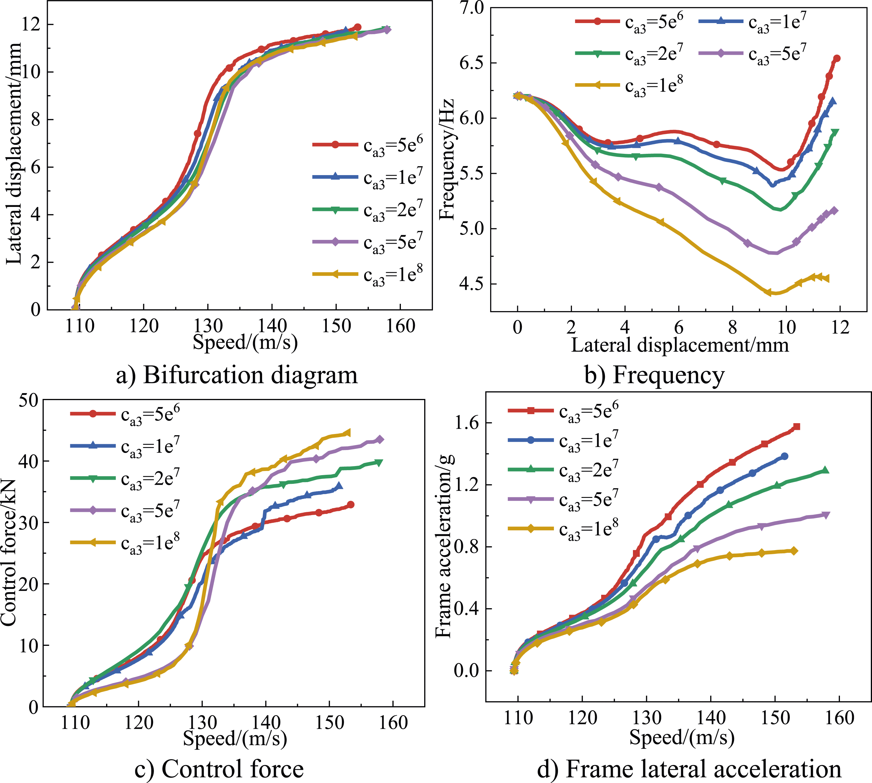
The nonlinear cubic stiffness and damping control is realized as j equals to 3. Figures 11 and 12, respectively, contain the bifurcation diagram, hunting frequency, control forces and frame lateral acceleration characteristics of the vehicle system. Analysis under cubic stiffness control. Analysis under cubic damping control.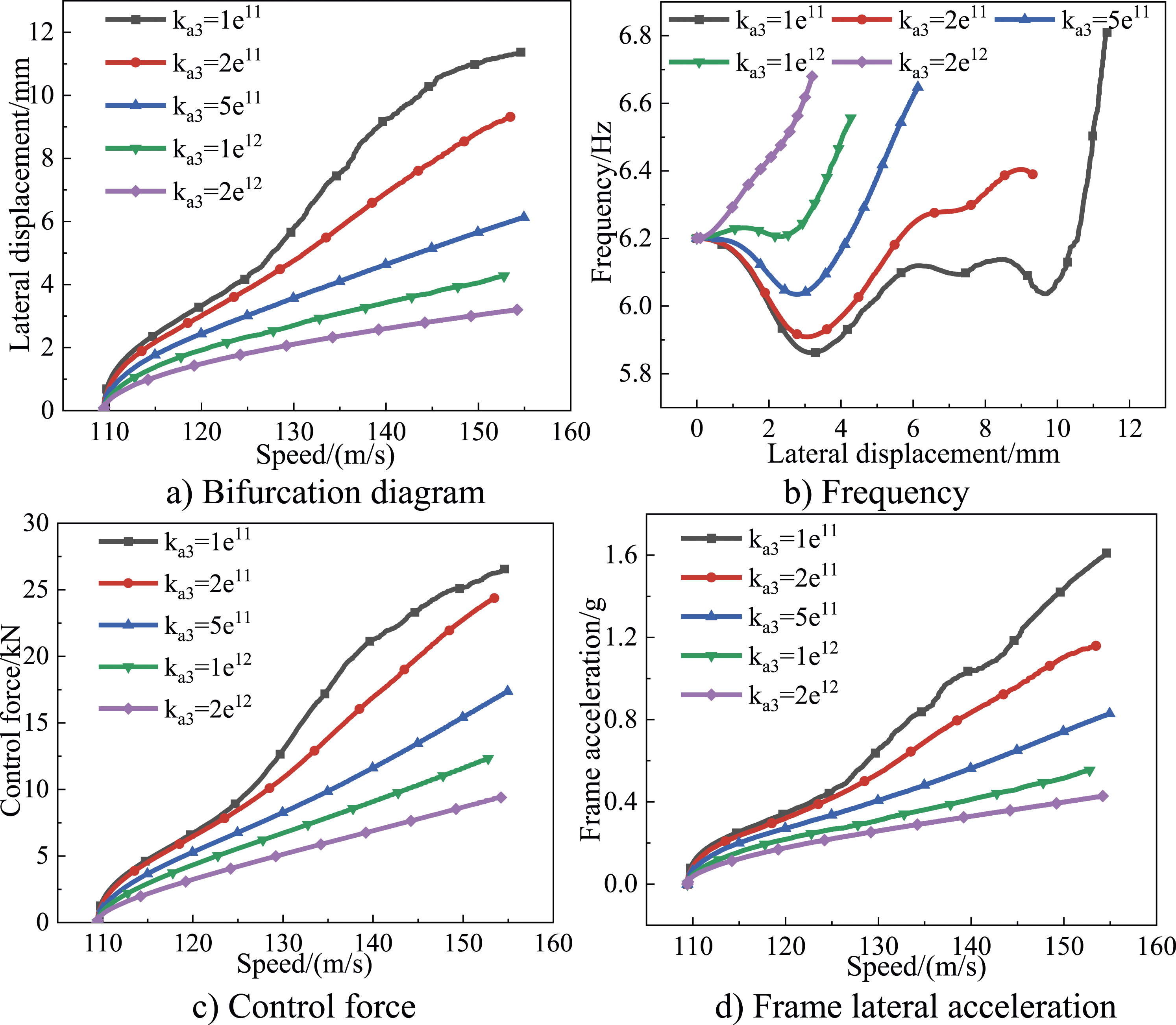
It can be seen from Figure 11 that under cubic stiffness control, the Hopf bifurcation point of vehicle system remains unchanged, which means the critical speed of vehicle system cannot be increased. However, the amplitudes of limit cycle and frame acceleration after bifurcation are greatly reduced, when the stiffness cubic term coefficient k a3 is greater than 1e12, the acceleration amplitude after instability is also lower than the alarm limit. Furthermore, the value of control force can be also minished in a large range. Moreover, the hunting frequency is also positively related to the cubic stiffness coefficient.
Apparently, the cubic damping control has little effect on Hopf bifurcation point and limit cycles. However, the cubic damping coefficient has a significant effect on reducing hunting frequency, and is better than the linear damping term. At the same time, it will greatly increase the value of control force. Coincidentally, with the increase of the cubic damping coefficient, the frame acceleration of vehicle system is also markedly reduced, which is profited from the damping effect on hunting frequency.
Hopf bifurcation in full-vehicle model
Full-vehicle model
DOF of full-vehicle system.
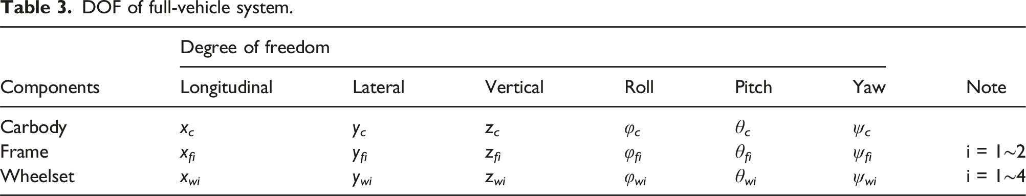
It should be added that unlike the simplified half-vehicle model, the full-vehicle model consists of two bogies, including eight yaw dampers in total. Therefore, four passive yaw dampers of the front and rear bogie will be substituted into active yaw dampers to perform real-time control. After the vehicle dynamics model is set up, its control signal passes through the SIMAT interface to implement real-time feedback adjustment. Figure 13 shows the co-simulation system of full-vehicle model with active yaw damper. Co-simulation system of vehicle with active yaw damper.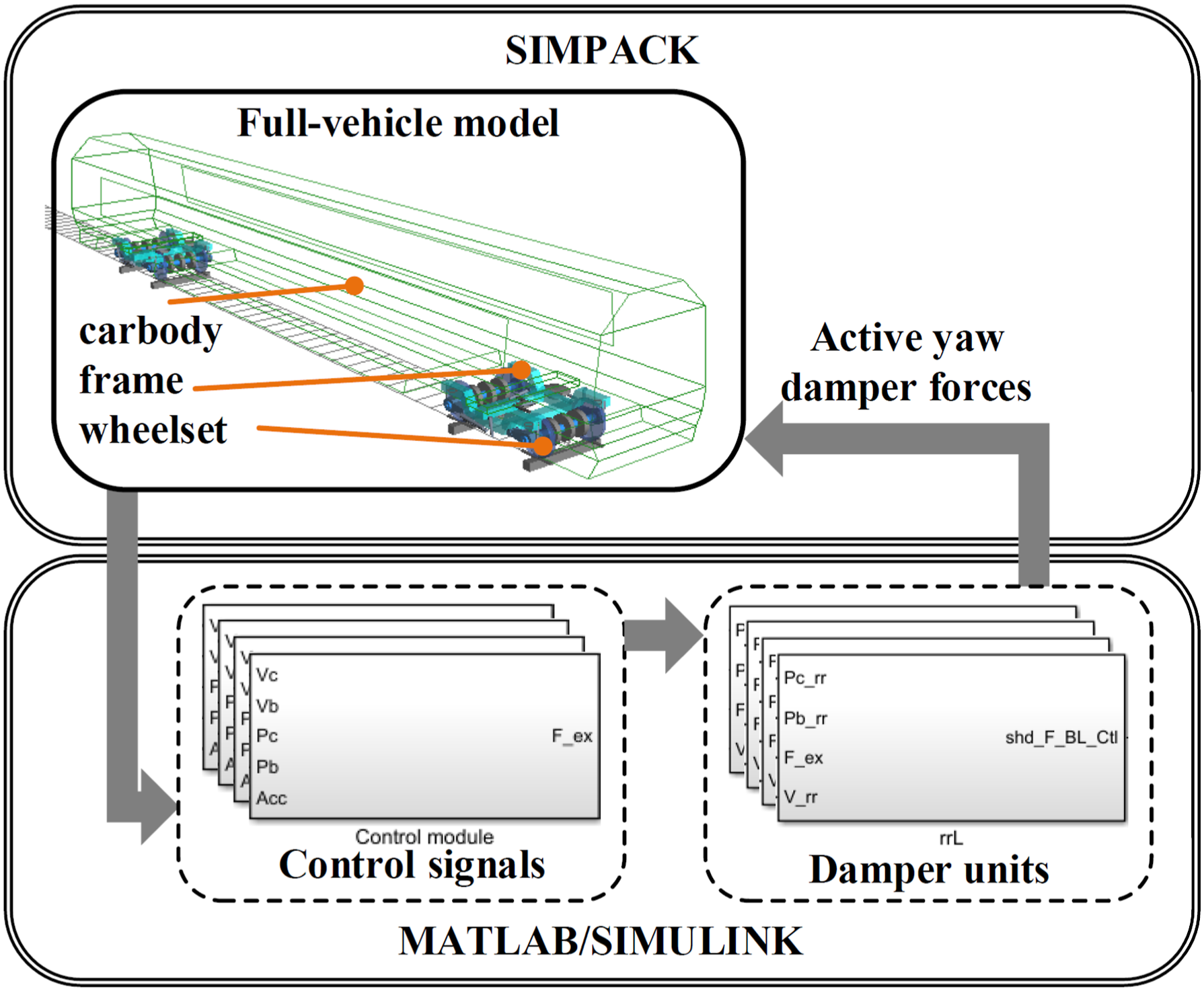
According to the control law obtained from analysis of the half-vehicle model, it is observed that the linear stiffness term can significantly delay the Hopf bifurcation point, the cubic stiffness term will prominently lower the amplitude of limit cycle after bifurcation, and the linear damping term is efficient in reducing limit cycle frequency. Hence, in full-vehicle model, the relative yaw motion between front frame and carbody is chosen as the control signal, with the linear stiffness & damping term and cubic term of stiffness are considered to analyse hunting stability of the vehicle system under active suspension.
Stability analysis
In the co-simulation of full-vehicle model, the initial lateral displacement of the guiding wheelset is set as 3 mm and the running speed as 400 km/h. The deceleration method is utilized to monitor in real time whether the lateral displacement of the wheelset converges to 0, which is the critical speed of vehicle system. Figure 14 (a) and (b) show the time domain diagram of the wheelset lateral displacement of the vehicle system decreasing with the speed under passive and active suspension, respectively, and c) is the frequency domain diagram of frame acceleration compared with the two conditions. Hunting stability analysis in full-vehicle model.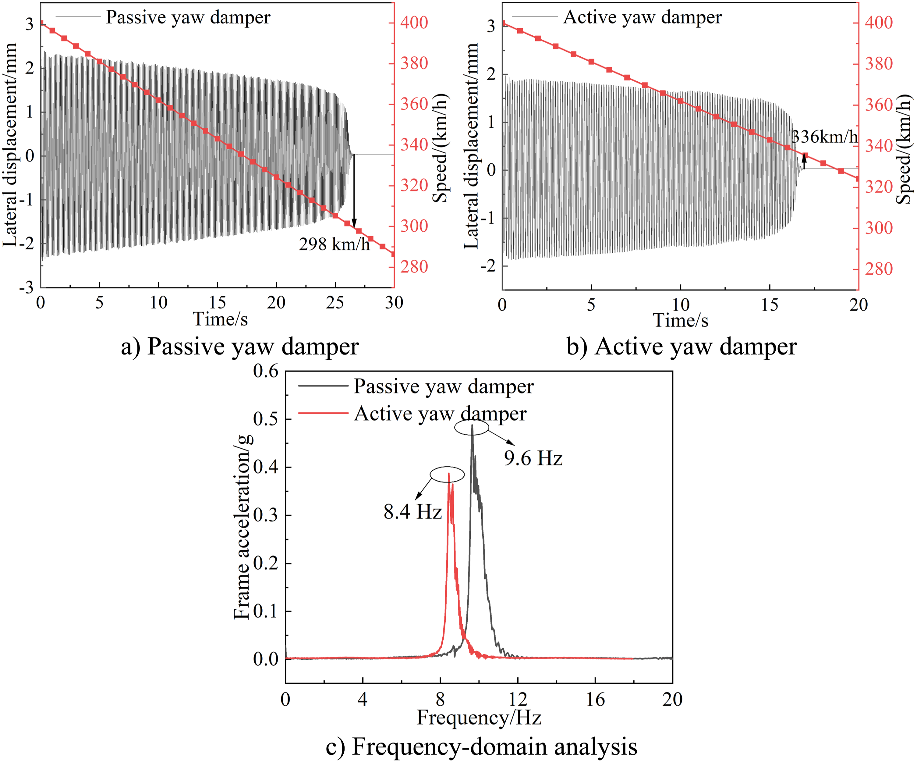
From the point of time domain, under identical initial conditions, the critical speed of full-vehicle system under passive suspension is 298 km/h, while the critical speed under active suspension is increased to 336 km/h. Meanwhile, the convergence time of the hunting motion under active suspension is also much smaller than that of passive suspension. On the other hand, from the frequency domain point of view, the hunting frequency of vehicle system decreases from 9.6 Hz to 8.4 Hz, and the frame acceleration also reduces significantly under active suspension. As a whole, the control law of active yaw damper through the yaw motion of frame has a good agreement with the simplified half-vehicle model.
Conclusions
In this paper, a 3-DOF simplified half-vehicle model is established, considering nonlinear wheel/rail forces and geometry relationship through field test. The hunting stability of vehicle system under passive and active yaw pamper has been compared and analysed, utilizing frame yaw motion control. Furthermore, the control strategy of stiffness and damping is applied to a full-vehicle model, which further proves the availability of the active yaw damper. The conclusions are summarized as follows: 1. The Hopf bifurcation point can be delayed using linear stiffness and damping control, that is, the critical speed of vehicle system can be increased. Notably, linear stiffness control can improve the critical speed more effectively than damping control. 2. For linear control terms, increasing stiffness leads to an increased hunting frequency for the vehicle system, while damping control serves to lower it. 3. Neither the stiffness nor the damping control force of nonlinear term can delay the Hopf bifurcation point, but the cubic stiffness term can effectively reduce the amplitude of limit cycle after instability, and the cubic term of damping is much more valid in reducing hunting frequency. 4. The effect of stiffness and damping control remain consistent between the full-vehicle model and the simplified half-vehicle model, thus demonstrating agreement across both scenarios.
In the further work, the active yaw damper on account of full-vehicle model using different control signals will be studied, and a bench test will be conducted to verify the feasibility of the control strategy.
Footnotes
Declaration of conflicting interests
The author(s) declared no potential conflicts of interest with respect to the research, authorship, and/or publication of this article.
Funding
The author(s) disclosed receipt of the following financial support for the research, authorship, and/or publication of this article: This work was supported by the National Natural Science Foundation of China (grant number U2034210, 52102441, 52002344), the TPL Independent R&D Project (grant number 2022TPL-T10), the Natural Science Foundation of Sichuan (grant number 2022NSFSC1886).