
Abstract
The panel cavity structure is one of the key components of the aircraft (vehicle) body and is among the main noise transmission pathways. Based on the modal superposition and Galerkin method, this paper realizes the theoretical model of sound insulation of the clamped, double-panel structure. The non-dominated sorting genetic algorithm-II (NSGA-II) is used to realize the sound insulation of the clamped double-panel structure. Through optimization, the fitting function and law of structural surface density and the optimized normal weighted sound insulation Pareto fronts were obtained. The results show that among the optimization, for the Pareto front cases, their double-panel thickness ratio h1/h2 is relatively far away from 1, and the corresponding cavity thickness H is relatively large. The influence of boundary conditions and size effects of lightweight sound insulation optimization are also discussed. The research on the influence of boundary and size indicates that the difference in the optimal weighted sound insulation Pareto fronts corresponding to the same surface density is mostly within the 1 dB range. Both the boundary and thickness of the panel will affect the frequency STL, while the boundary conditions or structure size changed, even the total thickness of panels needs to be the same, and the structure can also have similar weighted sound transmission loss (Rw) when the thickness ratio of the double-panel structure is chosen properly. The difference of material effects is also discussed. This research provides a method for the sound insulation optimization of clamped double-panel structures concerning the boundary and size effect.
Introduction
Plate structure is the key body structure of aircraft, high-speed trains, and automobiles, and its sound insulation performance directly affects the acoustic performance in the cabin.1,2 The sound insulation performance of double-panel cavity windows is even weaker due to their sightseeing function. Zhang et al. 3 found, through noise source identification, that the windows are one of the main sources of noise in high-speed trains. With reference to Wang’s wave propagation and modal superposition method, 4 they established the sound transmission model of a simply supported, double-panel window cavity on a train, and the variation in the amount of frequency sound insulation with varying panel thickness, cavity thickness, etc. was studied. Adhikary et al. 5 simulated the vibrational energy transfer through a turbulence boundary layer excited stiffened double-panel based on a fully coupled finite element model and found the stiffener orientation plays a major role in the energy transfer mechanism. Li et al.6,7 further studied the sound insulation of a simply supported, double-panel structure under turbulent flow as well as the optimization of the turbulent sound insulation of the same type of cavity filled with sound-absorbing materials. Xin et al.8,9 established a sound insulation theoretical model of a clamped, double-panel structure based on the modal superposition and the Galerkin method and verified the model through experiments. In practice, the clamped boundary condition is closer to the constraints on practical application. Guo et al. 10 studied the thermal effect on the sound transmission loss of simply supported double-panel partition. Anvariyeh et al. 11 gives the nonlinear vibro-acoustic behaviors of a double-panel structure and found that the excitation level, damping coefficient, and cavity depth have large effects on occurrence of jump phenomena in primary and super harmonic resonances.
To improve the sound insulation of panel cavity structures, researchers have proposed more complex structures. Aloufi et al. 12 used the acoustic impedance method to establish the sound insulation model of triple-, quadruple-, and quintuple-paned windows with same size and area mass. The results showed that the improvement in high-frequency sound transmission insulation can be achieved by increasing the number of window panels, while the low-frequency properties will be worse, especially at mass-spring resonances. This theory can apply to both simply supported and clamped boundary conditions. Based on the theoretical model, the authors further achieved active sound attenuation by applying active control forces on the inner Plexiglas panel or dimmable panel by installing the actuators on the boundaries of one of the two panels. 13 Ribas et al. 14 uses a simplified graphical method to evaluate the influence of the type of boundary connection of industrialized closing panel cavity structures on the estimation of the sound transmission loss. Related panel cavity sound insulation control also includes increasing the sound insulation of the double-panel cavity structure by installing magnetic-linked stiffness, 15 adding mass 16 or lateral local resonators. 17
Double-plate cavity structures are also widely used in building and other sound insulation fields. It is also the basis of complex plate cavity structures. While the improvement of sound insulation can be achieved through including the cavity layer between panels, the mass-air-mass resonance, namely, fMAM, occurs. 18 The fMAM results in the significant sound insulation valley value at the corresponding frequency. To improve this phenomenon, scholars have introduced the concept of metamaterials into the panel cavity structures.19–21 The effects of both the local resonance structure and absorbing materials on the sound insulation are researched.22,23 Talatahari et al. 24 studied the sound transmission loss of more complex double-walled electro-rheological fluid sandwich plates with functionally graded carbon nanotube reinforced composite facesheets, and found that increasing the electric field intensity, the soundproofing capacity of the proposed system, notably at the low-frequency values of mass-air-mass resonance will be improved.
Optimization is used as an approach to improve the sound transmission property while considering lightweight design.25–27 Zhou et al. 28 optimized the double-walled panel with poroelastic lining in the core for minimum weight and maximum acoustic transmission loss based on NSGA-II. Li et al. 7 further studied the optimization of sound insulation of double-walled panels with poroelastic lining under turbulent flow. NSGA-II 29 uses fast non-dominated sorting, which ensures the convergence and robustness of the algorithm, maintains the diversity of variables, and can handle complex nonlinear problems.
In summary, the double-panel cavity structure is the basis of the panel cavity structure and has received widespread attention. Research devoted to improving the sound insulation performance of it. The present work realized a theoretical STL model for the double-panel structure. To obtain the optimal sound insulation amount of the double-panel cavity structure under the corresponding area mass through optimizing. In this study NSGA-II is used for optimization.
In summary, optimization can find low-mass and high STL structures from the perspective of lightweight sound insulation design. However, optimization mainly focuses on simply supported double-plate cavity structures. There is little research on the optimization of clamped double-panel structures. Its influence of boundary conditions and sizes also need to be further studied. This paper refers to the theory of Xin,8,9 and a sound insulation theoretical model of a clamped, double-panel structure is established through the modal superposition and the Galerkin method. The second section mainly includes the introduction and verification of the theoretical model. The third section covers the optimization of weighted normal sound insulation. The influence of boundary, structure size, and material are also discussed. Finally, the last section is the conclusion.
Theoretical model and validation
A schematic diagram of the double-panel structure in which the boundaries are clamped is shown in Figure 1. The elevation and azimuth angle of incident wave are φ and θ, respectively. The velocity potentials of the incident sound field, air gap cavity, and radiation sound field are 𝜙1, 𝜙2, and 𝜙3, respectively. The thickness of the two panels and the cavity are h1, h2, and H, respectively. Schematic of STL through a clamped double-panel partition: (a) global view and (b) side view.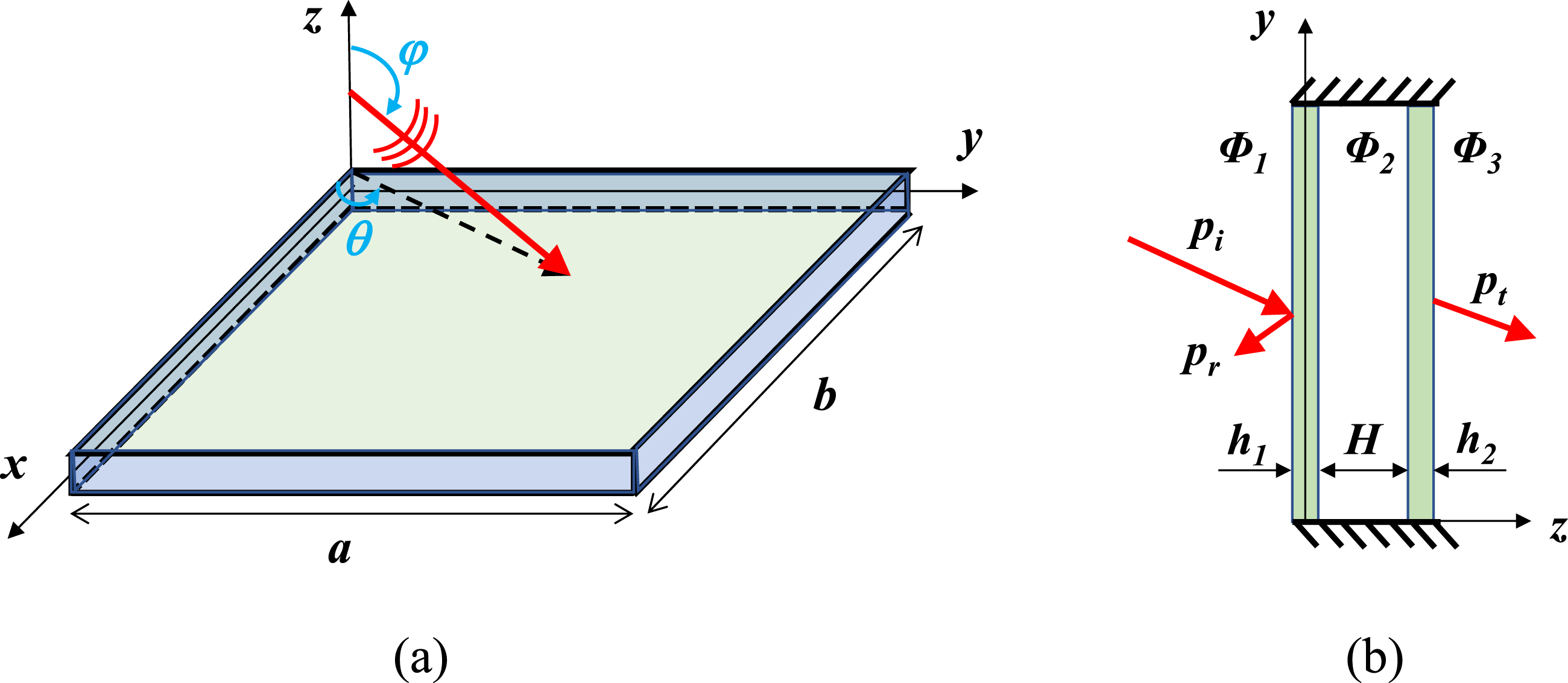
Vibration and response of panels
The sound velocity potential of a uniform plane incident sound wave can be expressed as


The sound pressure can be found from its relationship with velocity potential:


The velocity continuity boundary condition at the interface between each panel and the cavity satisfies the following:


Then it can be derived:


To solve for the panel displacement response amplitude coefficient, the Galerkin method is used:


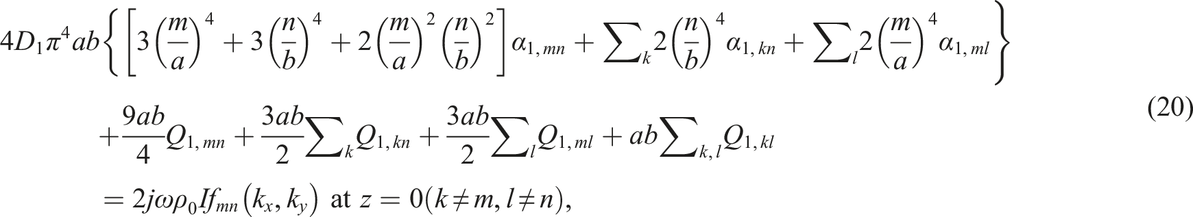
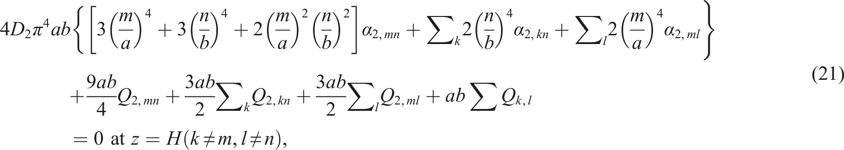
Substituting equations (5), (6), and (10)–(12) into (18) and (19) give the following:


The method written in matrix form is as follows:

The details of the elements of matrix T can be found in the Appendix of Xin’s paper. 9 By solving equation (25), the displacement amplitude coefficient of the panels and sound field velocity potential can be obtained.
Sound transmission loss
To solve the sound transmission loss (STL), the incident and radiation sound power is described first. The incident sound power and sound pressure is calculated as follows:


After applying the relationships of coefficient, the velocity potentials can be expressed as


By substituting the velocity potential expressions of equations (28) and (29) into the incident sound power equation (26), we can obtain the following:
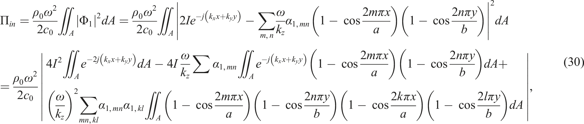
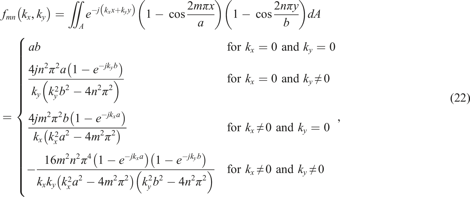
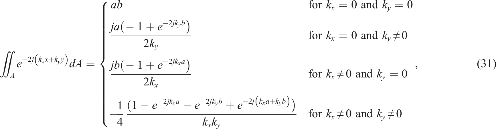
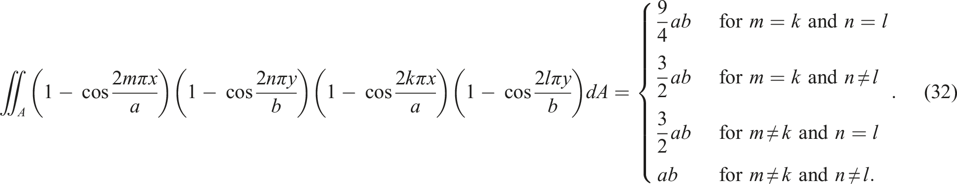
Among them, the two integral terms used are as follows:
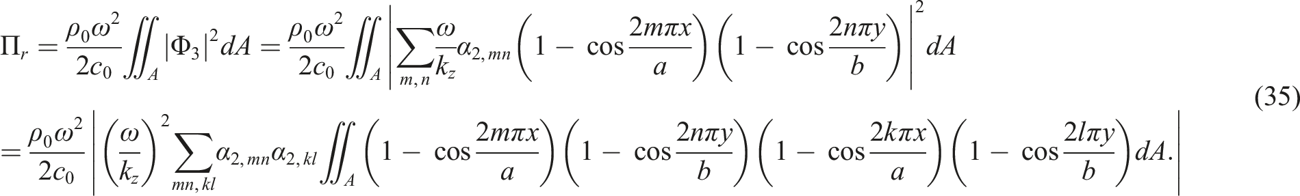
The radiation sound power and sound pressure is given as


By substituting the velocity potential equations (28) and (29) into the radiated sound equation (33), the radiation sound power is derived as


Once the displacement amplitude coefficient α1,mn and α2,mn of the panels is obtained through equation (25), it can be used by equation (37) to obtain the sound transmission loss.
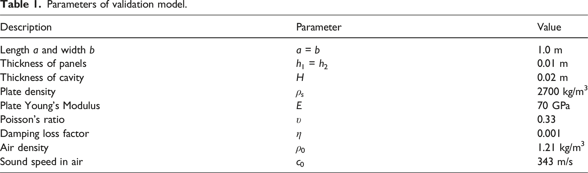
Model validation
Parameters of validation model.
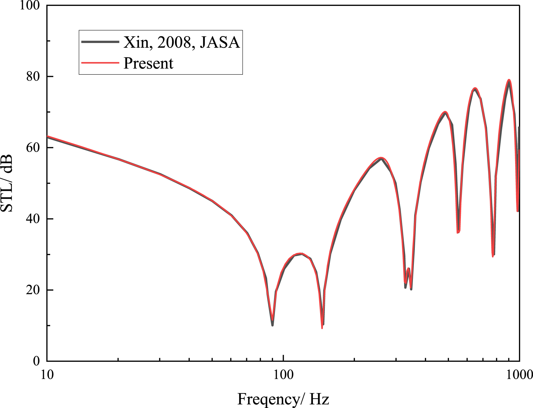
Validation of normal incident sound transmission loss. 8
STL optimization
In this section, the STL optimization parameters and results of Plexiglas clamped double-panel are discussed. The effects of different boundary condition, size, and material on the STL optimization of double-panel structure are discussed.
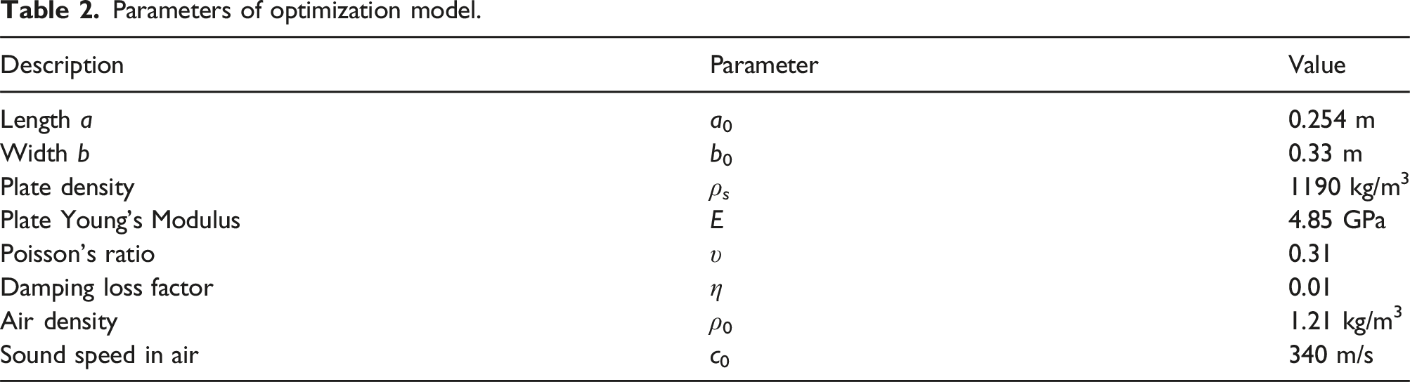
Structure and material parameters
Optimization parameters
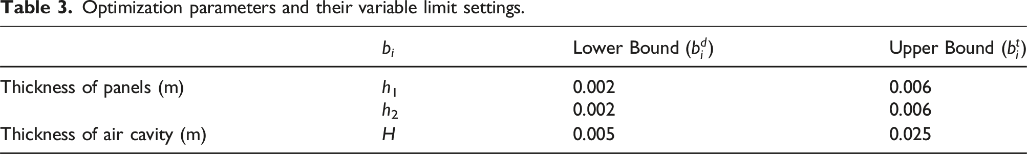
Optimization parameters and their variable limit settings.
The STL optimization is realized through the joint simulation of commercial software MATLAB and Isight.
31
The optimization procedure is illustrated in Figure 3. The theoretical STL is calculated in MATLAB. The NSGA-II is realized in Isight. The input of theoretical model is the optimization parameters list in Table 3 and updated by the NSGA-II. Illustration of STL optimization process.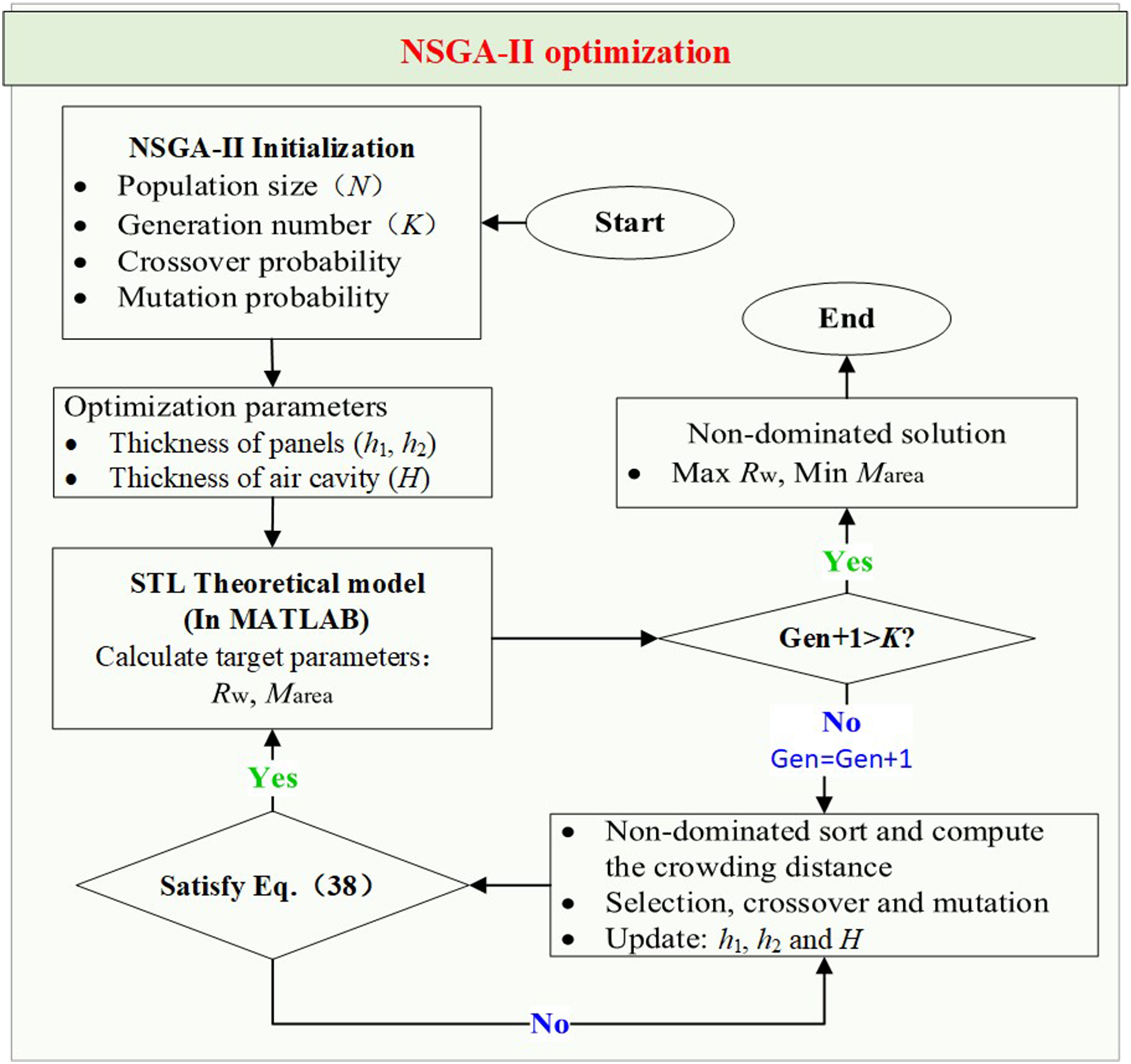
Optimization results
Figure 4 shows all the cases of optimization results. The horizontal axis is the surface density, and the vertical axis is the normal weighted sound insulation. Each point represents a clamped double-panel with specific panel thickness h1, h2, and cavity thickness H. The black points are all cases during the optimization process, while the red ones are Pareto front points, namely, better lightweight STL structure cases. By fitting the discrete points of the red cases, a cubic curve can fit the optimal working condition well. That is, under the condition when the areal density x range is about 5∼13 kg/m2, the optimal weighted sound insulation meets Rw = −4.64 + 10.07x − 0.91x2 + 0.029x3. Lightweight sound insulation optimization of clamped double-panel (a = a0, b = b0).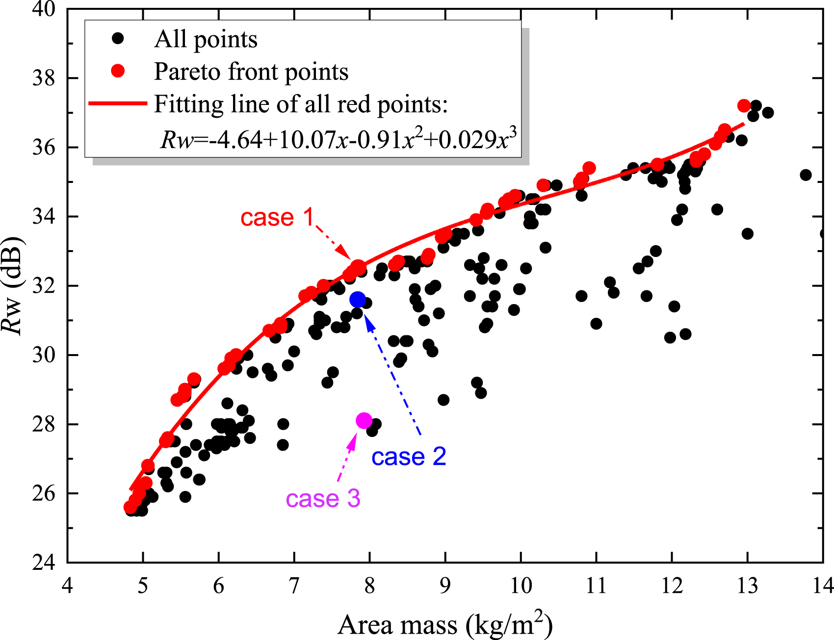


Parameters, Marea, and Rw of cases 1–3.
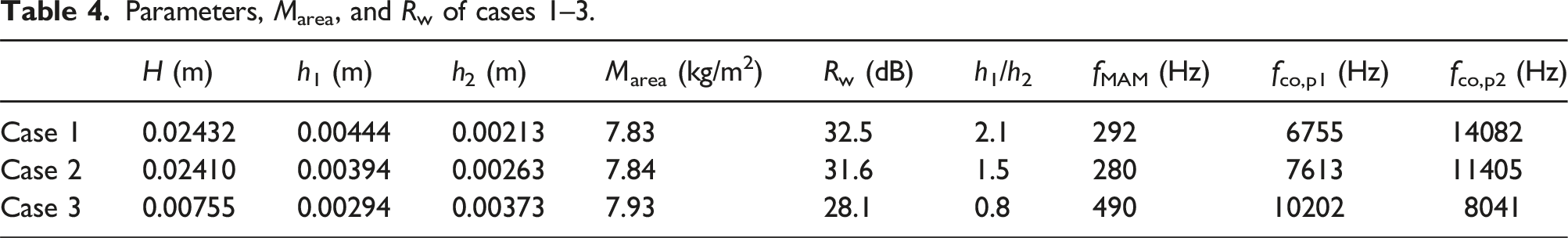
It can be seen that the “coincident frequency” of two panels, fco,p1 and fco,p2, of 3 cases are all far away from the 3500 Hz central frequency band of weighted STL. The “standing wave resonance” frequency of the cavity gap has the minimum value of 6800 within the considered H range and is also larger than 3500 Hz. They are not discussed in the following content.
The difference in panel thickness ratio h1/h2 between 1 is different for cases 1–3. Case 1 has the largest panel thickness ratio while case 3 has the smallest. The normal incident mass-air-mass frequency of a double-panel, fMAM, is also given as equation (39). The fMAM of case 1 and case 2 is close to 300 Hz, while the fMAM of case 3 is close to 500 Hz. The fMAM can also be seen in the corresponding narrow band of spectrum STL in Figure 5. It is worth noting that the theoretical fMAM calculated through equation (39) in Table 4 is a little bit smaller than that of the frequency dips in Figure 5(b). This may result from the clamped boundary conditions that make the stiffness of the structure larger compared to the free boundary condition. Comparison of frequency sound insulation between cases 1 and 3.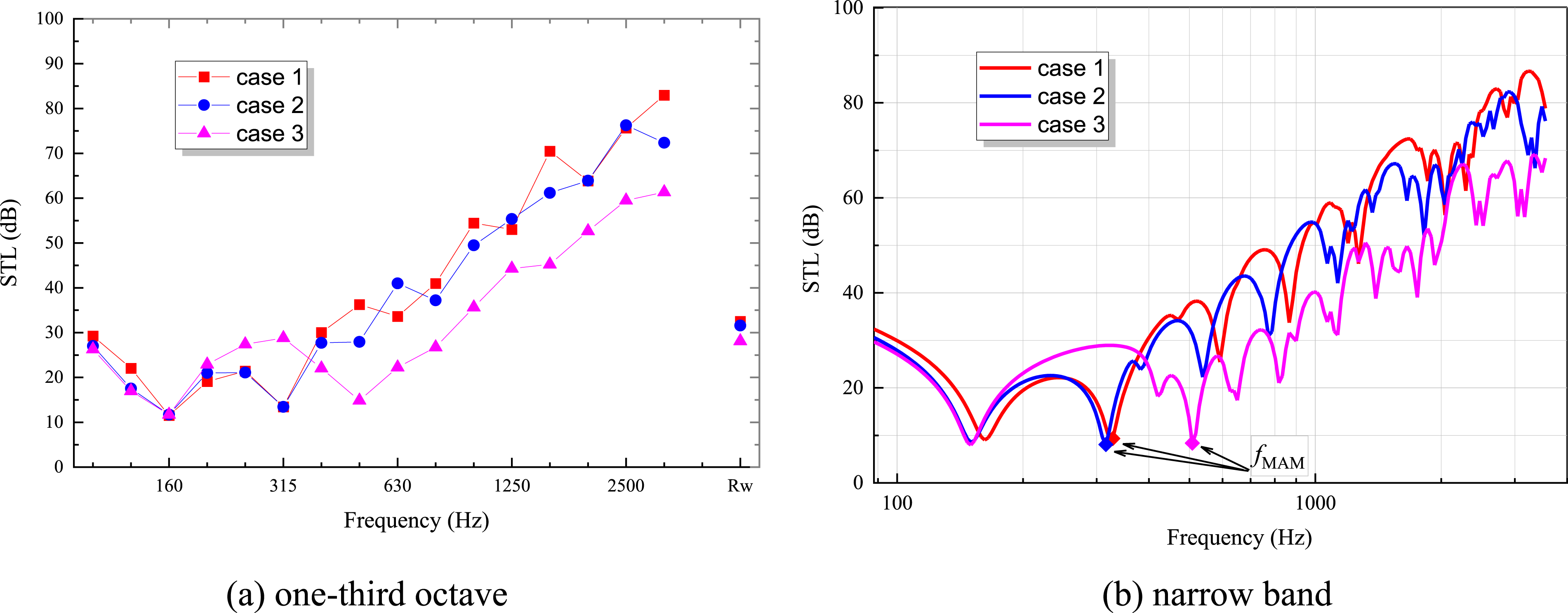
In Figure 5, the frequency sound insulation can be seen, and the valley value of case 1 and case 2 at the center frequency of 315 Hz is mainly caused by fMAM. The amount of frequency sound insulation in case 1 and case 2 is close below the center frequency of 400 Hz. Therefore, the difference in Rw is mainly due to mid- and high-frequency frequencies above 500 Hz. The cavity thickness and surface density of case 1 and case 2 are similar, and the main difference is the panel thickness ratio h1/h2. That is, the closer the panel thickness ratio is to 1, the closer the natural frequencies of the two panels are to each other, and the more significant the valley bandwidth. This phenomenon is better reflected in case 3, but in addition to h1/h2 being closer to 1, case 3 has a smaller cavity thickness H, which is about 1/3 of the cavity thickness of case 1 and case 2.
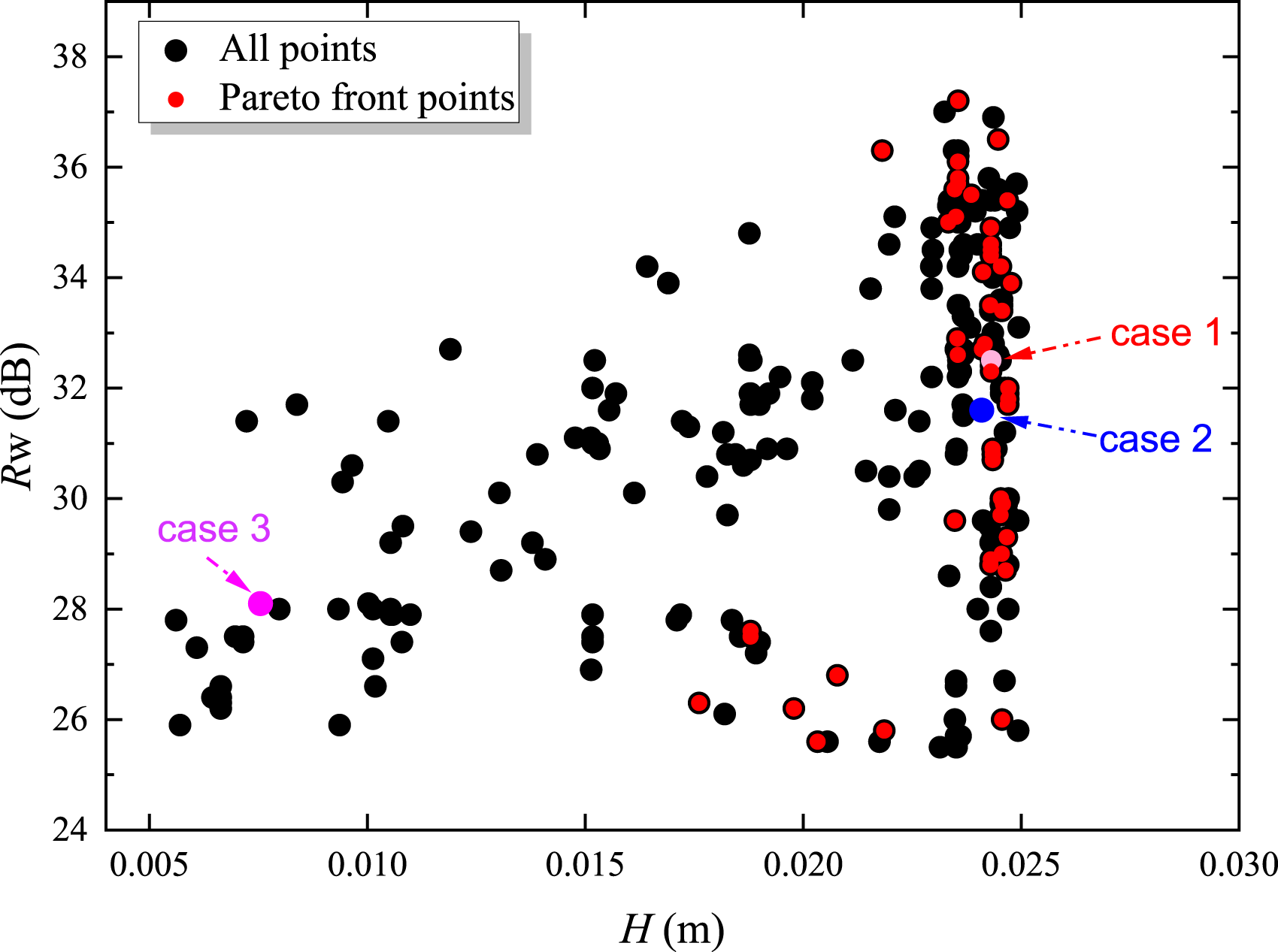
To further study the influence of h1/h2 and cavity thickness H on structural sound insulation, Figures 6 and 7 show the Pareto front points double-panel thickness ratio h1/h2 and cavity thickness H distribution in all cases during the optimization process. Pareto front points’ panel thickness ratio h1/h2 distribution. Pareto front points’ cavity thickness H distribution.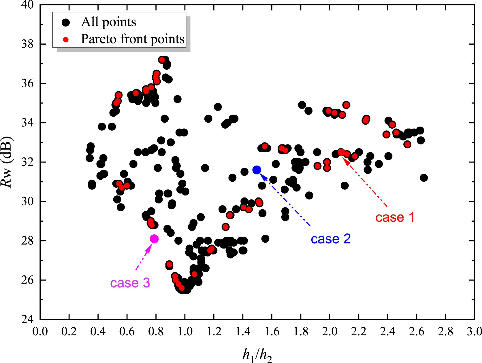
As can be seen in Figure 6, the thickness of the double-panel corresponding to the Pareto front points is rare when h1/h2 is close to 1. At the same time, when h1/h2 is greater than 1, the Rw of the Pareto front points increases as h1/h2 increases.
In Figure 7, overall, the cavity thickness H value corresponding to the Pareto front points is relatively large, that is, the structure with better sound insulation usually has a relatively large H value. For example, the H values of case 1 and case 2 are clearly greater than the H value of case 3.
Boundary effect
To compare the influence of the boundary on the normal weighted sound transmission loss of the double-panel cavity, the optimization results of the sound insulation of the structure under simple support are given. The sound insulation method of the simply supported double-plate cavity structure was introduced in the author’s previous paper.
3
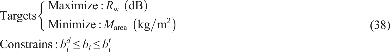
The other parameters and optimization methods are the same as the clamped structure in the previous section, namely, the structural parameters are the same as Table 2, the optimization target is the same as equation (38), and the optimization variables are the same as Table 3. The optimization results are shown in Figure 8 and the fitting curve of Marea and Rw are four orders. The comparison of two boundary conditions is show in Figure 9. Lightweight sound insulation optimization of simply supported double-panel (a = a0, b = b0). Lightweight sound insulation optimization fitting comparison of different boundary condition.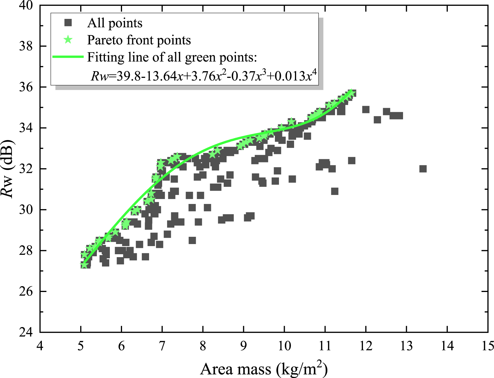
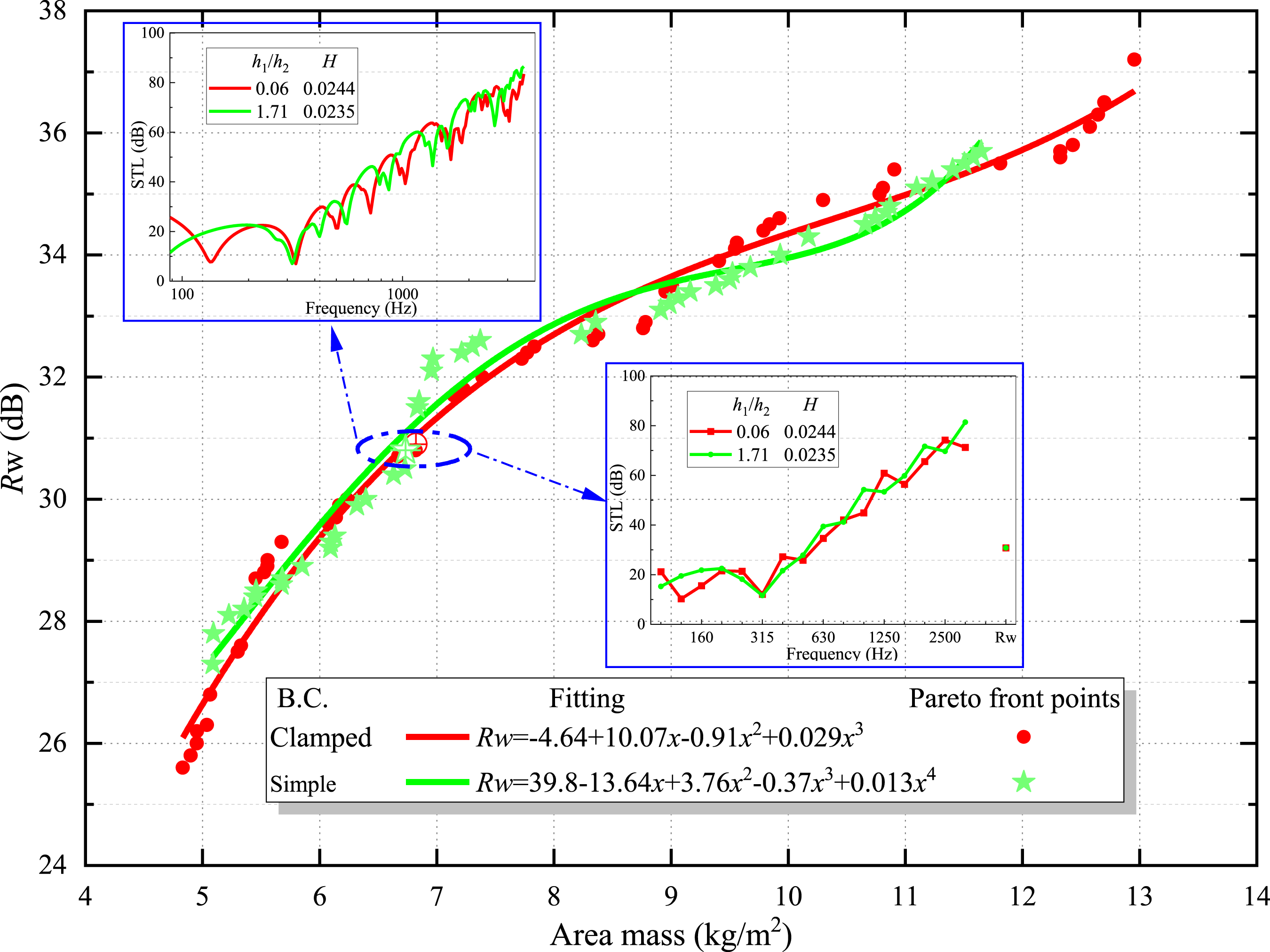
In Figure 9, the difference of Pareto fronts of Rw under same Marea is most within 1 dB. Here choosing 2 cases of different boundary conditions with area mass (6.8 kg/m2) and Rw (31 dB) to show the frequency spectrum (narrow band and one-third octave). Besides the clamped panel is stiffened with higher nature frequencies compared to the simply boundary, 9 there is also the influence of difference thickness ratio. However, combined with the boundary condition and thickness ratio, the overall Rw result the same.
Size effect
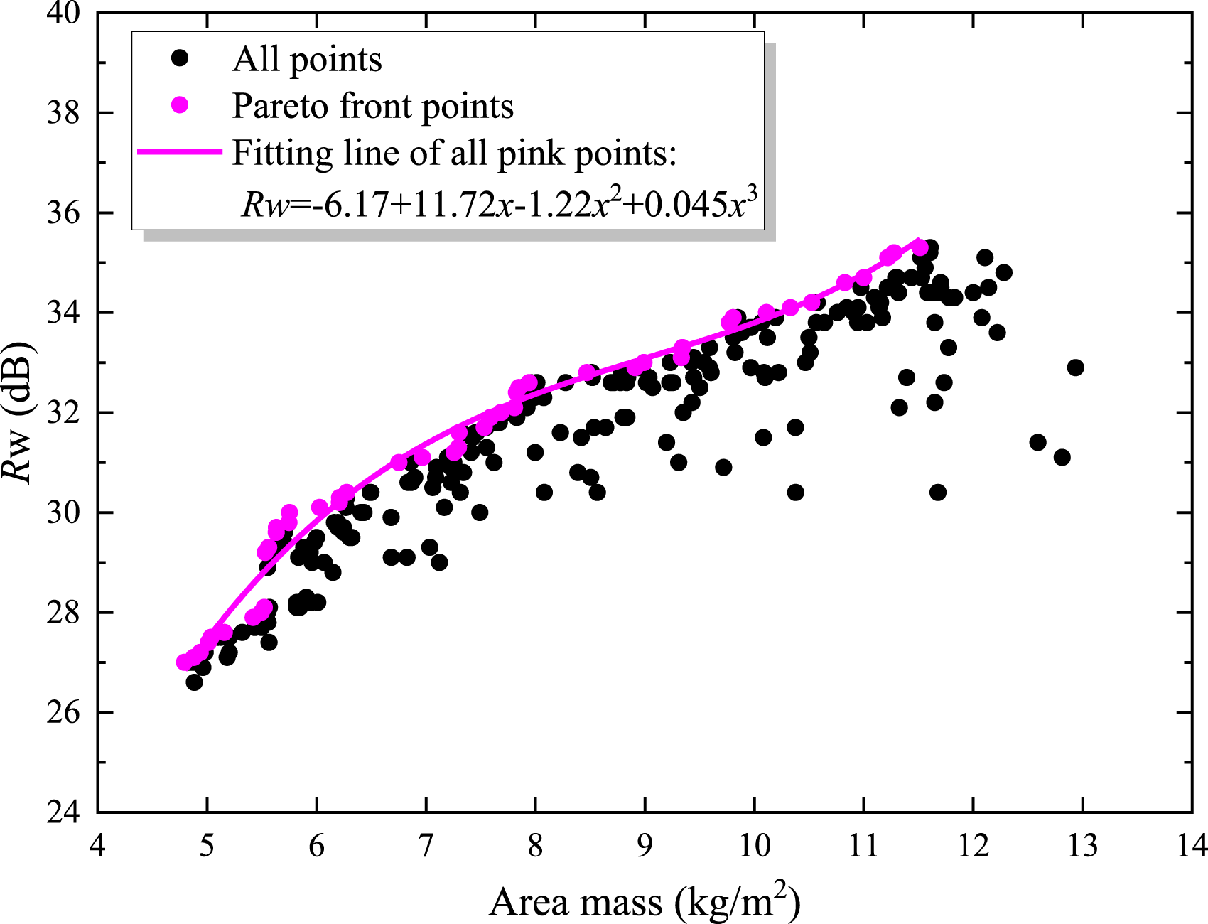
By fitting the Pareto front points of the optimization process, the relationship between the surface density and the optimal weighted sound insulation structure can be obtained. In the optimization of Figure 4, the length and width dimensions a*b of the structure are fixed to a0*b0 to study whether the fitting relationship between the surface density and the optimal weighted sound insulation of the clamped, double-panel structure changes with the size of the structure when other parameters remain unchanged. Therefore, when only the length and width of the structure are set to 1.5a0*b0 and 2a0*b0, respectively, the corresponding optimization results are shown in Figures 10 and 11, respectively. The lightweight sound insulation optimization results of the two structures, their surface density, and weighted sound insulation can be well fitted by the cubic curve as well. There are only certain differences in the expression coefficients of the fitting curves. Lightweight sound insulation optimization of clamped double-panel (a = 1.5a0, b = 1.5b0). Lightweight sound insulation optimization of clamped double-panel (a = 2a0, b = 2b0).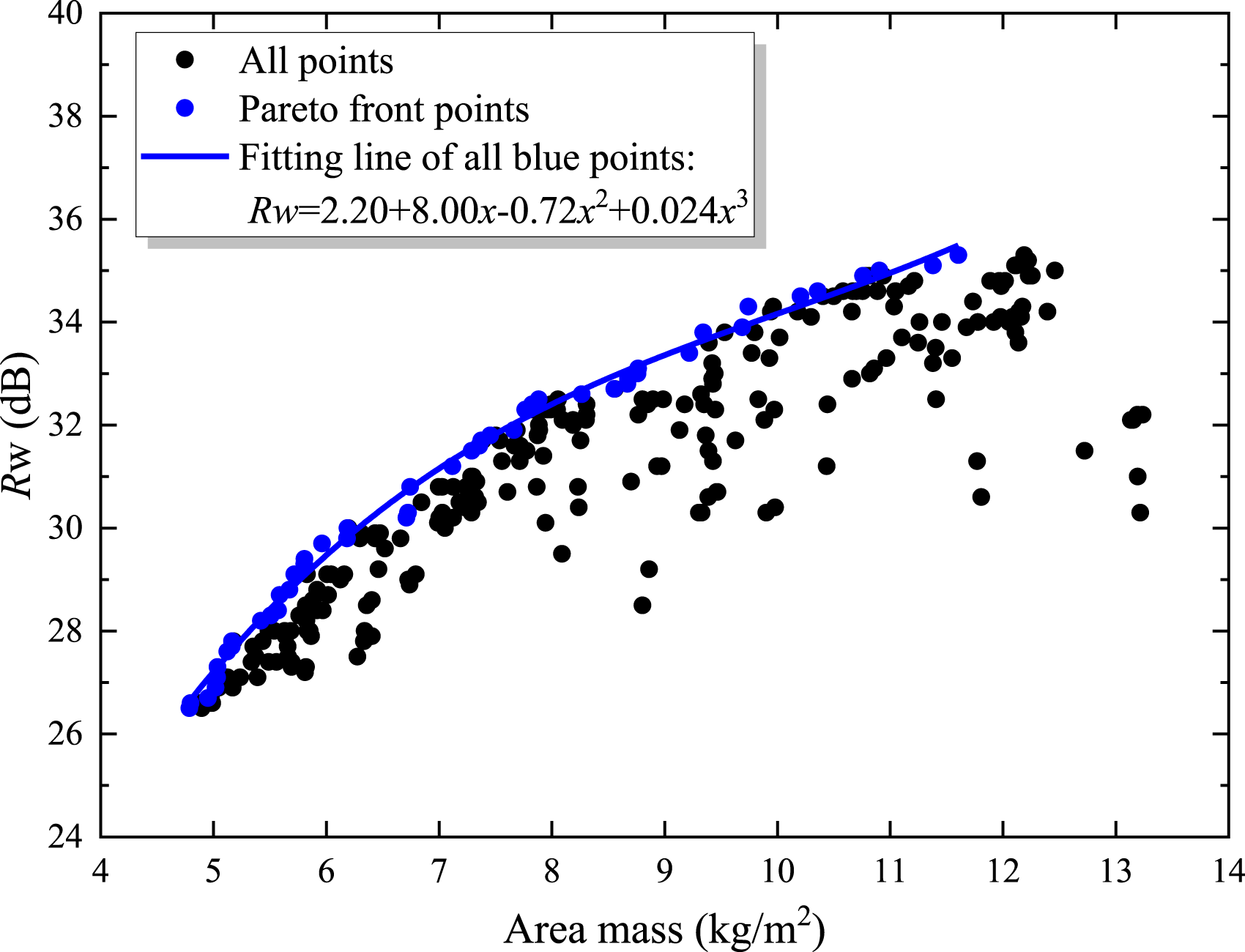
For comparison, the fitting results of Pareto front points with sizes a0*b0, 1.5a0*b0, and 2a0*b0 are put together in Figure 12. Although the fitting expressions under the three dimensions are different, within the area density range of concern, the size increases from a0*b0 to 2a0*b0, and the optimal weighted sound insulation difference corresponding to the same area density almost reaches the 1 dB range. Among them, when the area density is below 7 kg/m2, the fitted Rw corresponding to a0*b0 is slightly smaller than that of size 2a0*b0. When the area density is 7 ∼11.5 kg/m2, the fitted Rw corresponding to a0*b0 is slightly larger than that of size 2a0*b0. The fitted Rw corresponding to size 1.5a0*b0 is overall distributed between that of the other two sizes. The frequency spectrum (narrow band and one-third octave) property of STL are given for three cases of different size, whose area mass are close to 6.8 kg/m2 and Rw are around 31 dB. This reflect even if the structure has different size, when the total thickness of panels is fixed, the structure will have similar Rw when chose the thickness ratio properly. Lightweight sound insulation optimization fitting comparison of different clamped panel sizes.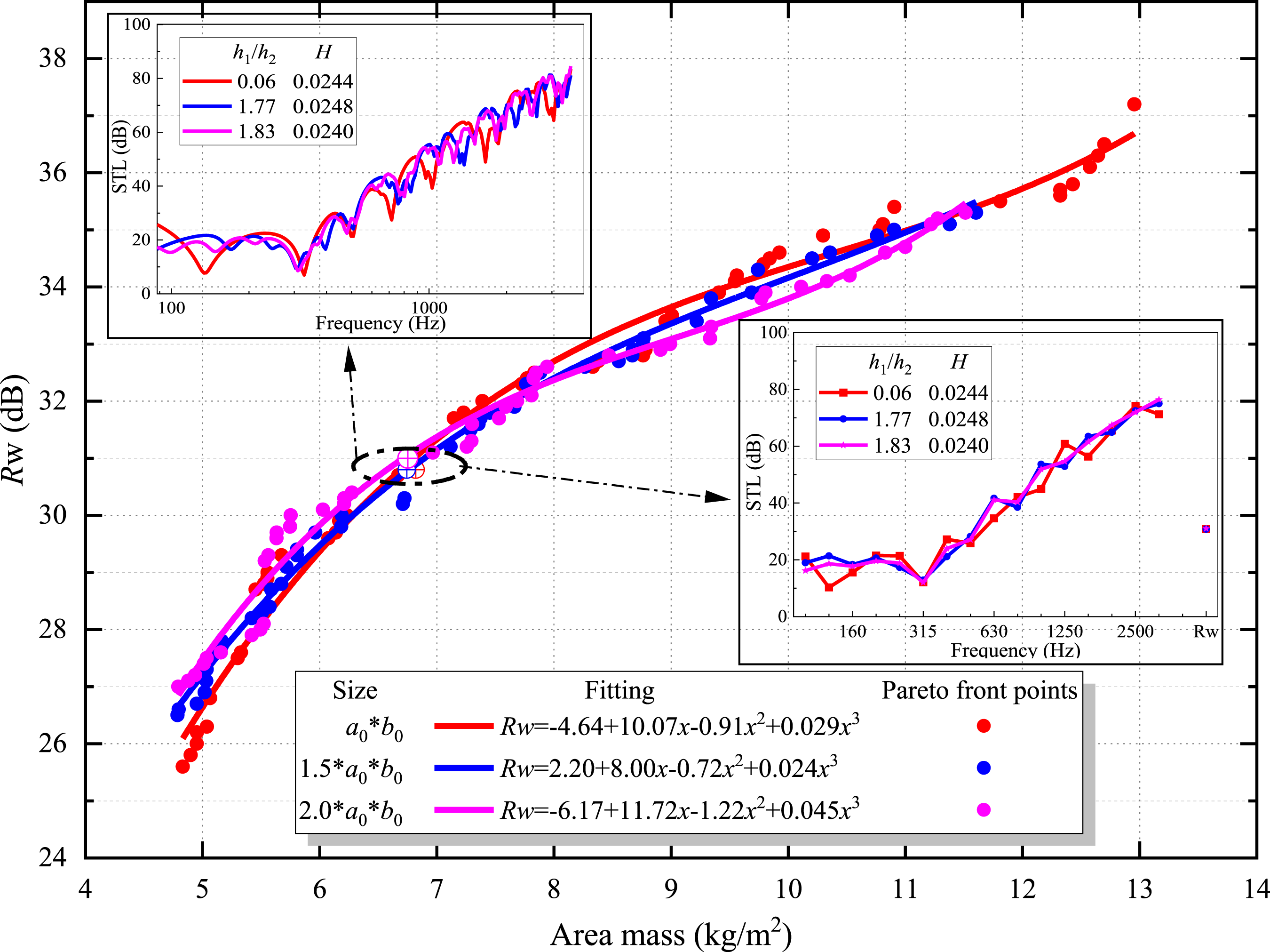
Further derivation of the cubic fitting curve is performed in Figure 13. The differentiated curve is a quadratic parabola. The increase in size will cause the location of the valley value and the extreme value of the parabola to change. That is, for size a0*b0, the growth rate of fitted Rw with respect to area density reaches a minimum value of 0.55 dB/kg/m2 at an area density of 10.5 kg/m2. For size 1.5a0*b0, the growth rate of fitted Rw reaches a minimum value of 0.80 dB/kg/m2 at an area density of 10.0 kg/m2. For size 2a0*b0, the growth rate of fitted Rw reaches a minimum value of 0.695 dB/kg/m2 at an area density of 9.0 kg/m2. In practice, to improve the weighted sound transmission loss, after determining the size, the fitting curve of Rw and surface density and its derivation can be obtained after optimization. When selecting parameters of lightweight STL design, the choice can be made by selecting the Pareto front points far away from the valley of the first derivative of cubic fitted Rw within the allowable range of structure strength. First derivative of cubic fitted Rw of different panel sizes.
Different material
Parameters of optimization model.
The optimized Rw and fitting curve of aluminum double-panel structure are shown in Figure 14. It can be obtained that the area mass and normal Rw satisfy the 4th order fitting. Figure 15 gives the fitting curve comparison of aluminum and Plexiglas double-panel cavity with the same boundary and size. Around area mass of 10.7 kg/m2, the double-panel cavity structures of the two materials have similar optimal Rw. When the areal density is less than 10.7 kg/m2, the normal Rw of Plexiglas is better, while over 10.7 kg/m2, the Rw of aluminum double-plate cavity structure is better. The one-third octave band of the two material structures at an area density of 10.7 kg/m2 with same Rw is given, which shows the difference in the spectrum distribution. Another spectrum diagrams of the two material structures with an area mass of 6.3 kg/m2 is given, the Plexiglas double-plate cavity structure has 1 dB higher Rw than that of aluminum, which is result from that the former has higher sound insulation in the frequency band above 800 Hz. Lightweight sound insulation optimization of clamped Aluminum double-panel (a = a0, b = b0). Optimization fitting comparison of different clamped panel materials.
Conclusions
Based on the modal superposition and Galerkin method, a theoretical model of sound insulation of a clamped, double-panel structure was realized. The optimization of normal sound insulation of a double-panel cavity structure was realized through the non-dominated genetic algorithm NSGA-II. The following conclusions were drawn. 1. Surface density and optimal normal weighted sound transmission loss of clamped, Plexiglas, double-panels satisfy cubic curve fitting, and that of aluminum structure satisfies quartic spline fitting. 2. The optimal Pareto front point cases of normal weighted sound transmission loss rarely have thickness ratio h1/h2 close to 1. This is because when the plate thickness ratio is close to 1, the natural frequencies of the double-panels are close, which reduces the overall sound insulation. Additionally, the cavity thickness H corresponding to the optimal cases is relatively large. 3. Investigation of the differences in the fitting curves of the optimal normal weighted sound transmission loss of the clamped, double-panel cavity under different sizes, namely, a0*b0, 1.5a0*b0, and 2a0*b0, shows that, although the fitting expressions under the three sizes are different, they are all cubic fitting curves, and, within the surface density range of concern, when the size increases from a0*b0 to 2a0*b0, the difference in weighted sound transmission loss is mostly within 1 dB. 4. Both boundary and thickness of the panel will affect the frequency STL, while the structure size or boundary conditions changed, even the total thickness of panels is fixed, the structure can also have similar Rw when chose the thickness ratio of double-panel structure properly. 5. The fitting curve of optimal normal weighted sound transmission loss varies according to different material. Comparison of the fitting curves of different material area mass and optimal sound insulation can intuitively show the better material for sound insulation in different area mass range.
This study provides methods for sound insulation design and optimization of double-panel cavity structures. In the future, the STL research of more complex panel cavity structures will be focused.
Footnotes
Author contributions
Yumei Zhang: Conceptualization, methodology, and writing—original draft. Ye Li: Data curation and validation. Dan Yao: Writing—review and editing. Yi Ai: Methodology and writing. Weijun Pan: Writing—review and editing. Yue Zhao: Methodology and writing—drawing.
Declaration of conflicting interests
The author(s) declared no potential conflicts of interest with respect to the research, authorship, and/or publication of this article.
Funding
The author(s) disclosed receipt of the following financial support for the research, authorship, and/or publication of this article: The present work is supported by the National Key R&D Program of China (No.2021YFF0603904), the National Nature Science Foundation of China (62203451) and Natural Science Foundation of Sichuan Province of China (2022NSFSC1897, 2023JDRC0004, and 2023NSFSC0902), Fundamental Research Funds for the Central Universities (24CAFUC01007).