
Abstract
We performed measurements of the sound reduction index and impact sound pressure level for a range of lightweight floating floors installed on a hollow-box timber floor. The measurements were performed in the laboratory according to the relevant standards. We tested different configurations, varying the cavity filling of the bare floor and the assembly of the lightweight floating floor. We tested floating floors with a continuous elastic layer with high and low dynamic stiffness, floating floors on elastic load-bearing units and a basic vinyl covering of the bare floor. The results show that a wide range of sound insulation can be achieved, making the hollow-box floor elements suitable for different purposes. Best performance is achieved with elastic load-bearing units installed on the bare floor with gravel in the cavity. Detailed analysis of the achievable sound insulation improvement is also given. This shows that reasonably reliable predictions can be made using well-known equations from the literature. Key parameters are the resonance frequency of the system, determined by the mass per unit area of the bare floor and of the floating floor as well as the dynamic stiffness of the resilient layer, and the configuration of the elastic layer. The results and the highlighted prediction equation offer a solid basis to help develop solutions to meet different sound insulation requirements and make the hollow-box floor elements suitable for urban buildings with several purposes, ranging from office/commercial to educational and residential.
Keywords
Introduction
Wood-based structural systems for modern urban buildings are being developed in many countries, especially in Europe and North America. When floor spans larger than 5–6 m are required, we observe an increased use of ribbed or hollow-box floor structures.1 –3 They are an efficient solution in terms of material use and performance. As opposed to traditional construction 4 or solid cross-laminated timber (CLT) floor slabs, 5 acoustic solutions combined with timber hollow boxes are little documented in the literature. The aim of this paper is to present the results from measurements we performed with a focus on lightweight solutions. These results extend and complement the data we presented in a previous paper on hollow-box floor constructions. 6
The measurements were performed in the context of the Woodsol project. The project was founded by the Norwegian Research Council to support broader use of timber construction in the volume market, that is, for urban buildings with four to nine floors. The project aims to develop an industrialised structural solution based on moment-resisting wooden frames, with long floor spans and high architectural flexibility. Moment resistance is achieved by connecting the floor element to the glulam columns by means of special steel connectors. Bracing is no longer required. This will increase the competitiveness of timber construction when compared to traditional building systems based on steel and concrete and ease their use in an increased number of buildings.
The paper is structured as follows: in section 2 we describe the method and measurement setup. In section 3, we present the tested floor assemblies. In section 4, we present the measurement results. In section 5, we focus on the analysis of the obtained improvements and in section 6, we present our conclusions.
Measurement method and setup
We performed the measurements at the SINTEF Community acoustic laboratory in Oslo. We used the vertical sound transmission suite and performed the measurements according to standard EN ISO 10140-2:2010 7 and EN ISO 10140-3:2010. 8 The receiving room volume was 200 m3 and the test opening measured 2.8 m × 3.7 m. The width of the opening was reduced to 2.4 m using concrete elements to fit the size of the test elements. This resulted in a specimen area of 8.9 m2, slightly below the 10 m2 requirement given in the standard. This is expected to have a minor effect on the accuracy of the results. The cross-section of the tested elements is suitable for floor spans up to 9 m. For a discussion on how the results will be affected in a longer span, we refer to Conta. 9 Figure 1 illustrates the installation of the floor element for testing. In line with the standard, airborne sound was generated by a dodecahedron loudspeaker and impact sound was generated by a standard tapping machine.
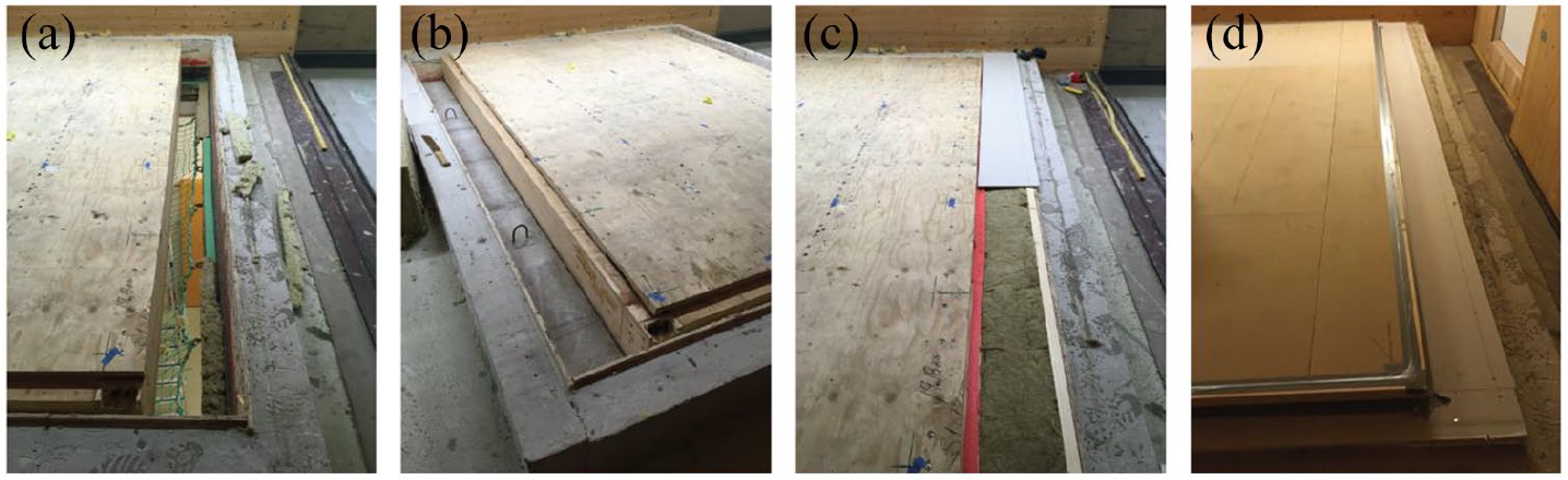
Installation of the floor element in the laboratory: (a) element lifted in place, (b) concrete fitting elements positioned, (c) filling of the cavity with mineral wool and plasterboard and (d) floor element with installed lightweight floating floor ready for measurements.
Floor assemblies
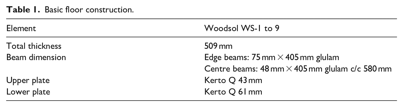
Table 1 lists the components of the bare floor. The corresponding cross-section is shown in Figure 2. Note that these dimensions are those required to fulfil the comfort criteria with a floor span of 9 m. They were kept to ensure compatibility of the results with other investigations in the project. 10 The cavity was either empty, filled with gravel or filled with absorbing material (wood fibre).
Basic floor construction.
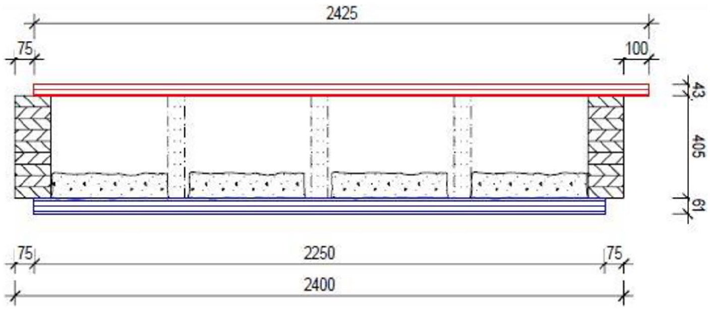
Cross-section of the Woodsol floor element including gravel.
Figure 3 shows the different floor assemblies measured in the laboratory. The test is based on three main categories: basic floor without additional layers except a vinyl floor covering, floating floor on continuously elastic layer and floating floor on elastic load-bearing supports.
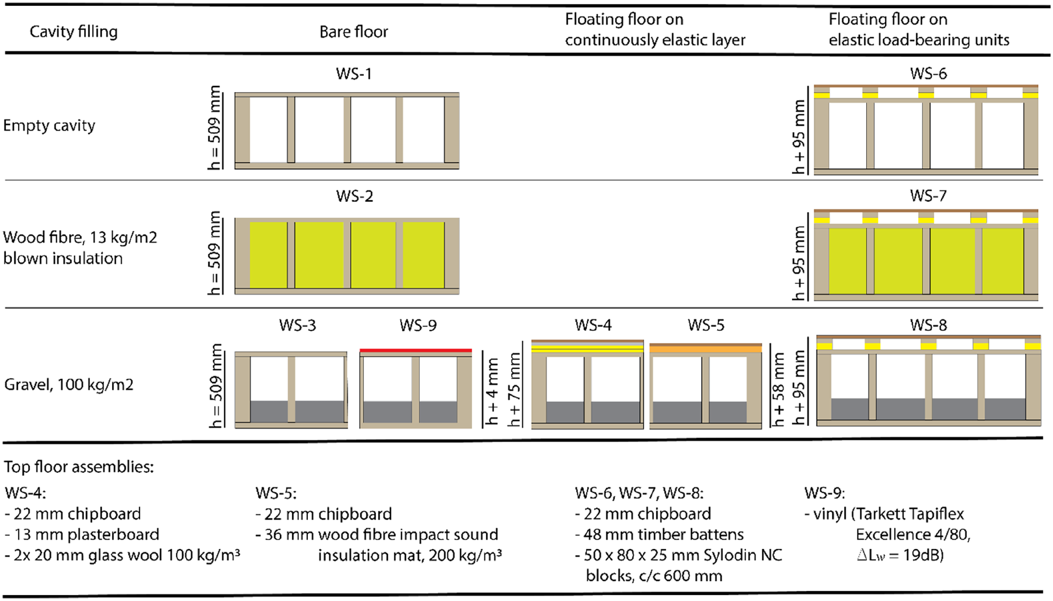
Overview of the tested configurations.
Measurement results
Table 2 shows an overview of the results from the measurements including the weighted sound reduction index Rw, with the corresponding spectrum adaptation term C50–5000, the weighted impact sound pressure level Ln,w and the corresponding spectrum adaptation term CI,50–2500 along with the total floor mass (including the cavity filling). Measured frequency spectra are presented in sections 4.1 to 4.3.
Key results from Woodsol floor measurements.
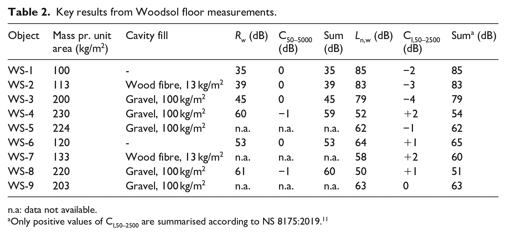
n.a: data not available.
Only positive values of CI,50–2500 are summarised according to NS 8175:2019. 11
Bare floor
Figure 4 presents the sound reduction index and normalised impact sound level for the bare floor. Results for three configurations are presented: empty cavity, 100 kg/m2 gravel installed in the cavity and cavity filled with sound-absorbing material (wood fibre, 13 kg/m2). In addition, we include the impact sound pressure level obtained with a vinyl floor installed on the bare floor with gravel inside the cavity.
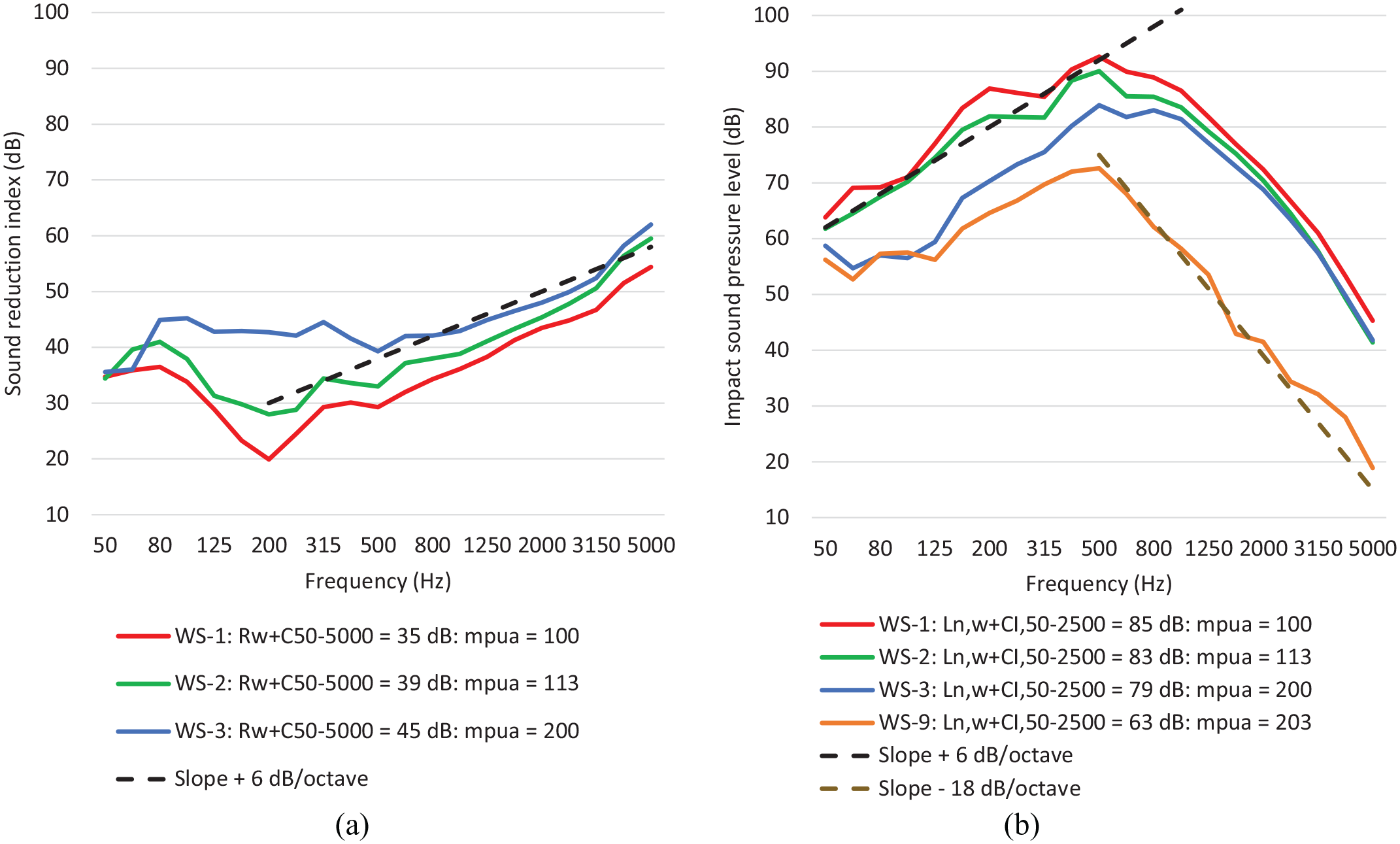
(a) Left: sound reduction index and (b) right: impact sound pressure level values for the bare floor configurations.
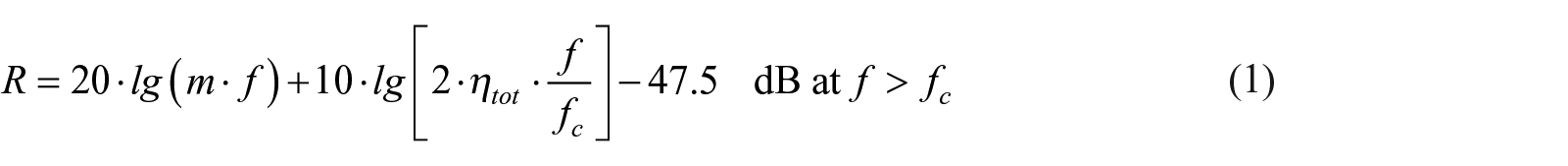
The sound reduction index results for the investigated configurations are clearly different. The configuration with gravel in the cavity delivers the highest sound insulation. The values are 5–10 dB higher than the other configurations, with even higher differences below 1000 Hz. The sound reduction index for the configuration with gravel in the cavity is almost frequency independent up to 1000 Hz. At higher frequencies, the slope is close to 6 dB/octave. As expected, the configuration with empty cavity delivers the lowest values of sound reduction, with a minimum in the coincidence region for the Kerto plate around 200 Hz. 12 From this region on, the sound insulation increases by approximately 6 dB per octave. This is clearly below the slope of 9 dB/octave that is expected above the resonance frequency for a single plate or a double construction with rigid connections 13 :
Single plate:
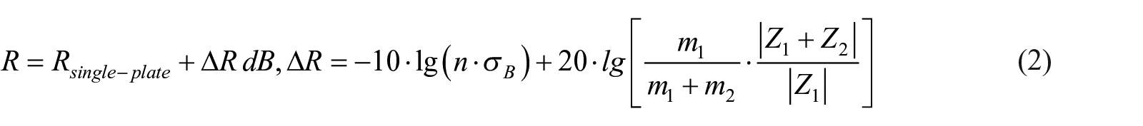
Double construction with rigid connections:
where m is the mass per unit area of the plate, f is the frequency,
It is also interesting to observe that while the improvement due to the additional mass of the gravel is rather large, increasing the sound absorption in the cavity, for example, by adding wood fibre, only improves the sound reduction index by about 4 dB in the same frequency range.
When looking at the impact sound insulation, we observe a similar ranking of the configurations as seen above: the empty cavity delivers the highest impact sound pressure levels. Adding gravel in the cavity effectively reduces the levels, by as much as 10–15 dB at frequencies below 500 Hz. Wood fibre in the cavity improves the impact sound pressure level by about 3 dB in the same frequency range. Above 800 Hz, the surface hardness of the top plate (Kerto, laminated veneer lumber) is the governing parameter, and we see that all three configurations without floor covering perform in a very similar way. The configurations with vinyl (WS-9) perform dramatically better, likely due to softer surface.
Looking at the slope of the curves, we can identify two regions that are valid for all the configurations. Firstly, below 500 Hz, impact sound pressure level increases by approximately 6 dB per octave, independent of whether the cavity is filled or not. This is a similar slope to hollow concrete floors without a covering. 13 Secondly, above approximately 800 Hz, the level decreases by about 18 dB/octave, both for the configurations without a floor covering and with vinyl floor covering. This frequency dependency coincides with the theory for lightweight floors where the slope is completely determined by the specific mass of the hammer at sufficiently high frequencies.
Lightweight floating floor on continuously elastic layer
Figure 5 presents the measured sound reduction index (a) and the impact sound levels (b) for the configurations based on a continuously elastic layer. Two different types of elastic layers were selected: one with low dynamic stiffness (mineral wool) and one with higher dynamic stiffness (wood fibre). The measurements were performed with 100 kg/m2 gravel in the bare floor cavity.
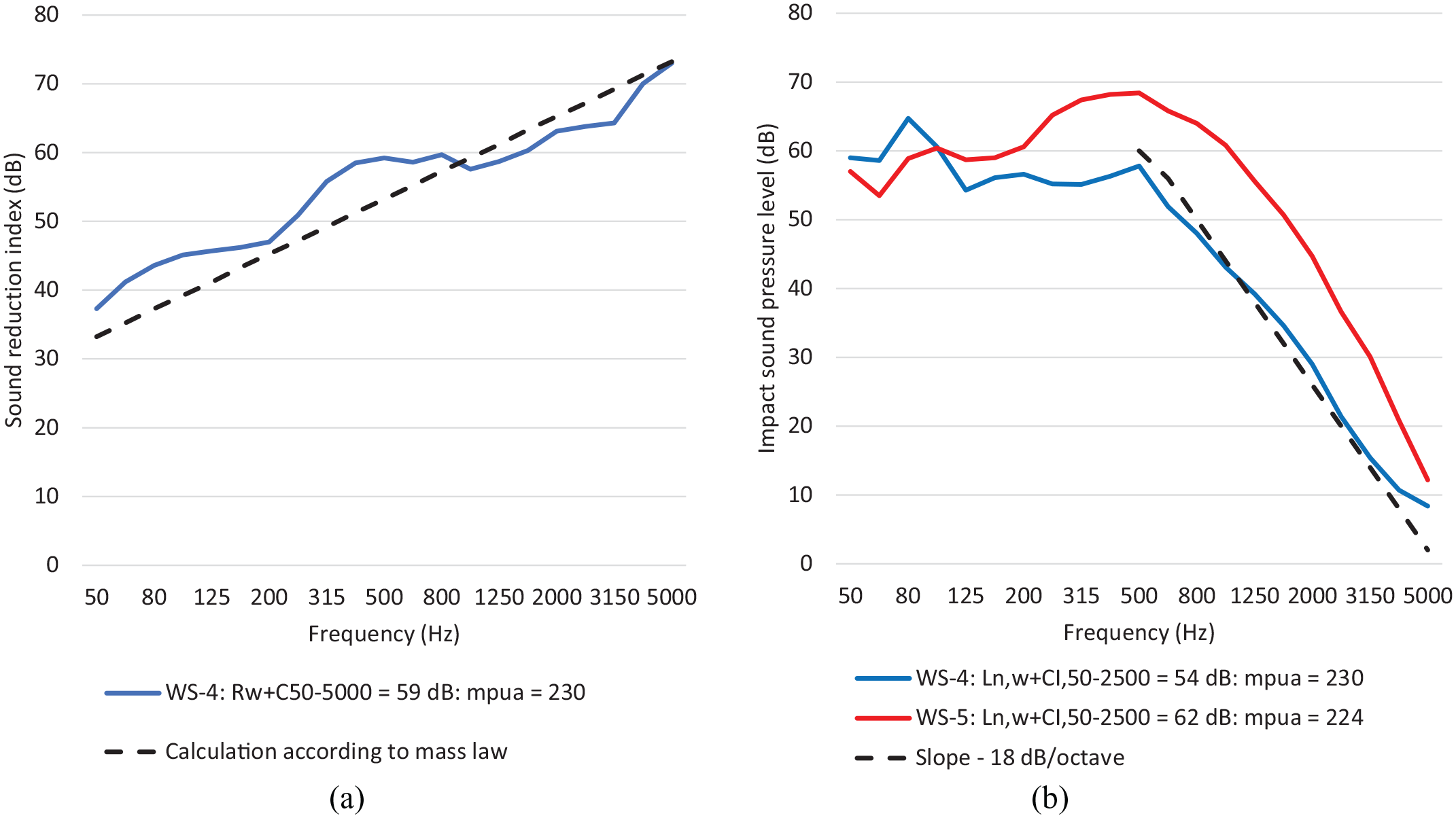
(a) Left: sound reduction index and (b) right: impact sound pressure level values for assemblies with a floating floor on a continuously elastic layer.
The measured sound reduction values closely match the calculations according to the mass law based on the total mass per unit area of the element, using the following equation 13 :

where m is the mass per unit area of the complete floor assembly and f is the frequency.
At frequencies below 500 Hz, the measured values exceed the predicted values. The measurement results of the sound reduction index show that this solution could fulfil the requirements for apartment buildings in several European countries. The smooth spectrum leads to a favourable low value of the spectrum adaptation term C50–5000 = −1.
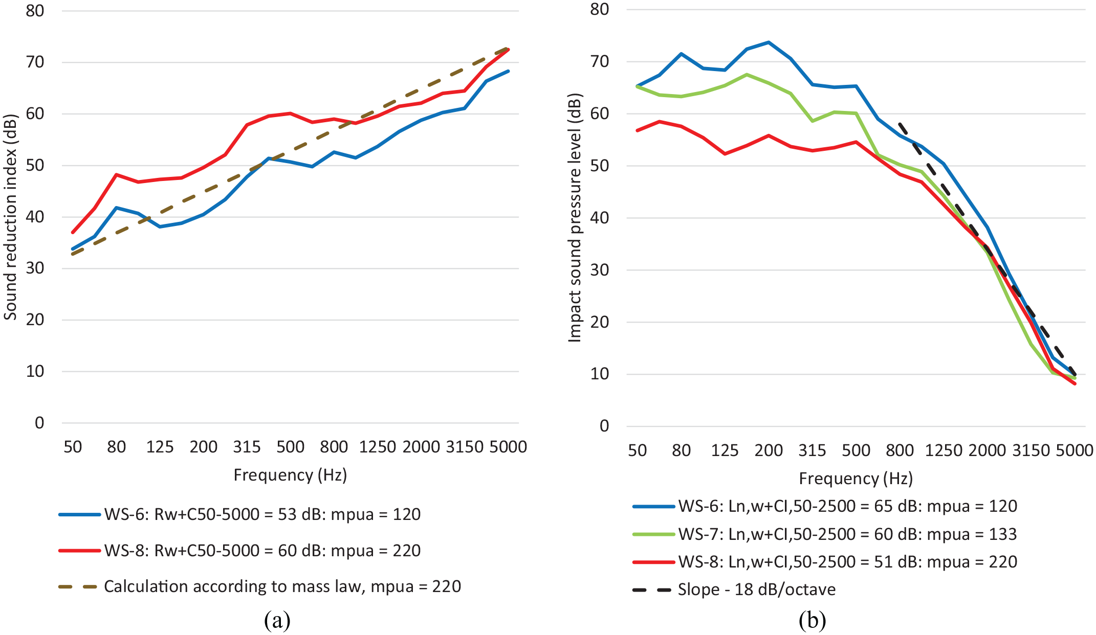
The normalised impact sound level for the solution with mineral wool as the elastic layer (WS-4) shows a maximum at 80 Hz, corresponding to the resonance frequency of the floating floor, fo, ~75 Hz calculated according to the following equation 13 :
where m1 is the mass per unit area of the bare floor, m2 is the mass per unit area of the floating floor (gypsum board + plywood) and sd is the dynamic stiffness of the elastic layer.
Between 100 and 500 Hz, the impact sound pressure level is approximately constant. Above 500 Hz, the impact sound pressure level decreases with a slope of 18 dB/octave. This is the same slope as we observed for the bare floor and theoretical behaviour mentioned in the previous section. We do not recognise the resonance frequency of the floating floor in the results for the solution with wood fibre as the elastic layer (WS-5). The highest impact sound pressure level values are registered in the medium frequency range (300–500 Hz) and are probably due to the relatively high stiffness of the elastic layer. Comparing the high dynamic stiffness with low dynamic stiffness, we observe a difference larger than 10 dB in a wide range of the frequency spectrum. As seen in Table 2, this corresponds to a difference of 8 dB on the single number quantity Ln,w + CI,50–2500.
Lightweight floating floor on elastic load-bearing units
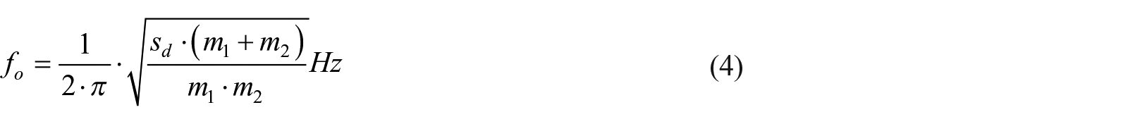
Figure 6 presents the measured sound reduction (a) and the normalised impact sound pressure level (b) for the solutions based on a lightweight floating floor on elastic load-bearing units. Results from these measurements include an empty cavity, with gravel in the cavity and with wood fibre in the cavity, as shown in Figure 2.
(a) Left: sound reduction index and (b) right: impact sound pressure level values for assemblies with a floating floor on elastic load-bearing units.
Above 500 Hz, the trend of the sound reduction index can be approximated by the mass law calculated according to (3) with the total mass per unit area of the element, both for the solution with an empty cavity and with gravel in the cavity.
However, in the lower frequency range, this calculation underestimates the result by up to 10 dB.
The sound reduction index difference between the two solutions is almost frequency independent in the frequency range below 800 Hz and amounts to about 10 dB. We observe approximately the same difference when looking at the single number quantities. The difference in Rw + C50–5000 amounts to 7 dB. As for the solutions with a continuous elastic layer, the high sound reduction index makes them suitable to fulfil the requirements for apartment buildings in several European countries; see overview table in [6].
The results for the impact sound pressure levels show a clear dependency on the cavity filling, with the solution with gravel (WS-8) performing best and the solution with an empty cavity performing worst (WS-6). Although the difference in Ln,w is up to 14 dB, all three solutions show low values for the spectrum adaptation term CI,50–2500 (+1, +2). Below 1250 Hz, the effect of the gravel in the cavity on the impact sound pressure level is even larger than the effect we observed on the sound reduction index. Above 500 Hz, the impact sound pressure level decreases by 18 dB/octave for all three solutions, similarly to the general behaviour of lightweight floors.
Analysis of the improvement obtained with different solutions
In this chapter, we focus on the improvement of the airborne and impact sound insulation using different solutions. We look first at the effect of the cavity filling with assemblies with a continuously elastic layer (section 5.1) and with elastic load-bearing units (section 5.2). Then we compare the performance of the assemblies with a continuously elastic layer with those based on elastic load-bearing units (section 5.3). Finally, we look at the effect of the vinyl floor covering (section 5.4).
Comparison of the assemblies with a continuously elastic layer
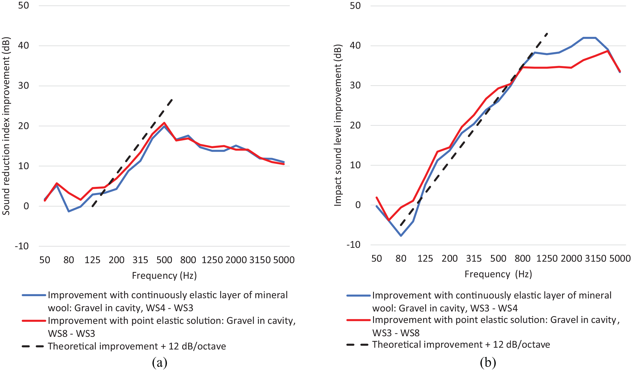
Figure 7 shows the improvement of the airborne and impact sound insulation for a continuously elastic top floor including gravel in the cavity. The results regarding single number quantities are given in Table 3.
Continuously elastic top floor, gravel in the cavity.
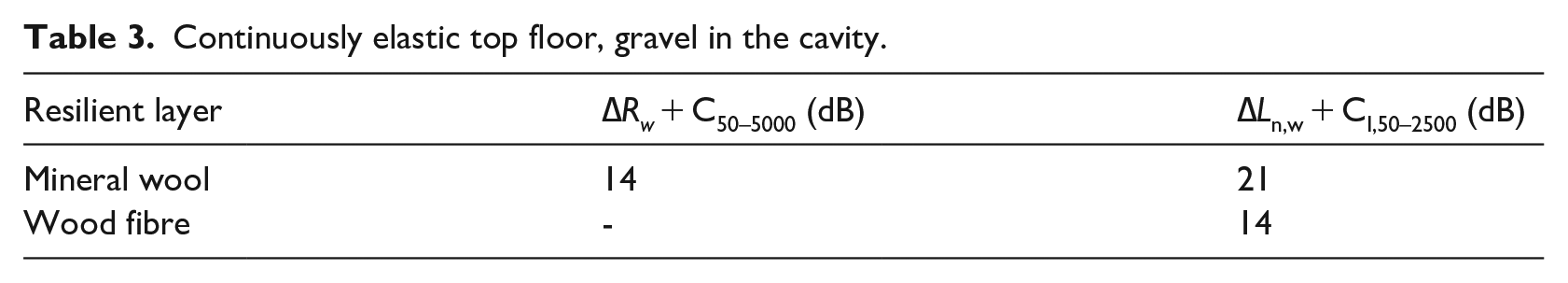
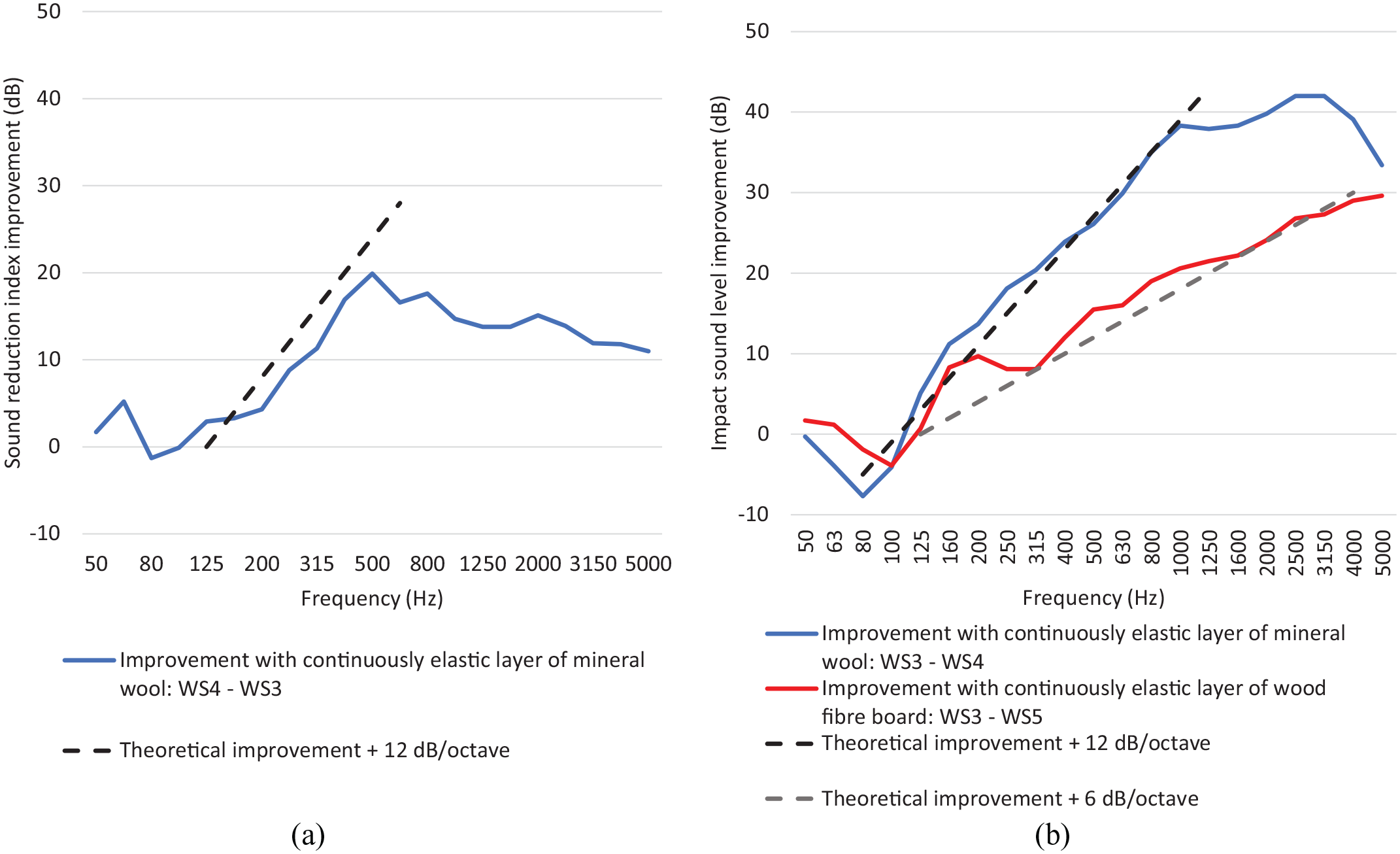
Improvement due to continuously elastic top floor: (a) left: sound reduction index and (b) right: impact sound insulation.
A continuously elastic top floor based on mineral wool shows a significant improvement in the airborne sound insulation from the resonance frequency of the mass-spring-mass system. The slope of the improvement coincides with analytical calculations according to the following equation:
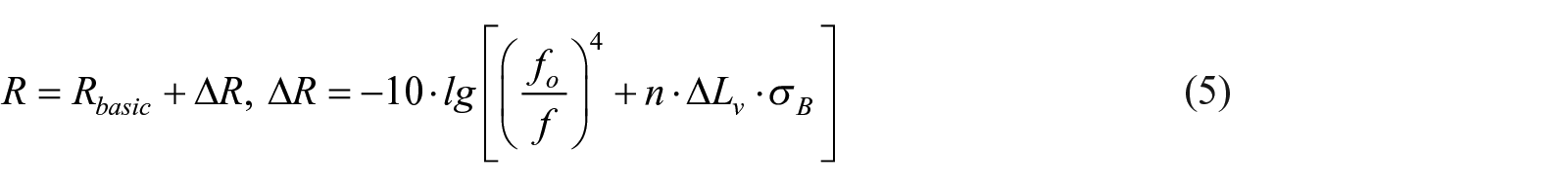
where Rbasic is the sound reduction index of the bare floor, f0 is the resonance frequency calculated according to equation (4) and ∆Lv is the vibration level difference between the bare floor and the floating floor.
When we assume that the ratio between the velocity of the primary floor and the velocity of the ‘bridges’ are frequency independent, the improvement will increase by 12 dB per octave until it reaches a maximum, a plateau. The maximum will be determined by the critical frequency of the upper plate and the degree of mechanical contact between the floor elements, 13 in this case at approximately 500 Hz. The slope of the improvement coincides with calculations according to (5).
Both types of resilient layers show a significant improvement in the impact sound insulation towards higher frequencies from a resonance frequency, f0, determined by the properties of the mass-spring-mass system according to equation (4). For the mineral wool solution, f0 is approximately 71 Hz, where we observe a significant drop in the improvement curve. The drop is less visible for the porous wood fibre product (fo ≈ 106 Hz). The slope of the improvement is, however, significantly different. The slope of the improvement from the mineral wool solution is approximately 12 dB/octave. This frequency dependency coincides to a high degree with the analytical calculation of a lightweight floating floor on a rigid subfloor based on the following well-known equation 13 :
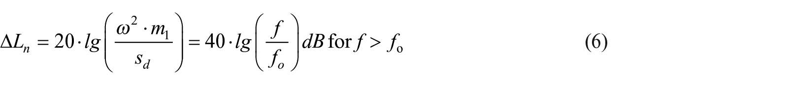
The slope of the improvement using the porous wood fibre solution is close to 6 dB/octave, probably determined by significantly higher damping properties of the wood fibre structure. The principal behaviour coincides with the general effect of the transmissibility in a vibrating system with high damping properties. This effect also explains the reduced improvement drop at the resonance frequency of the system.
Comparison of the assemblies with elastic load-bearing units
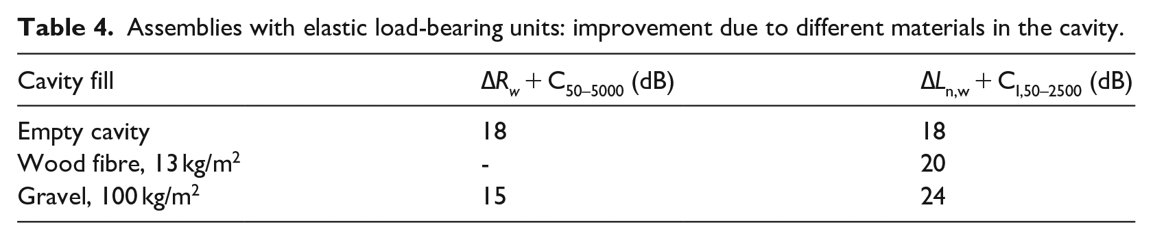
Figure 8 shows the improvement of the airborne and impact sound insulation for the point elastic top floor solution for different cavity fill materials. The results regarding single number quantities are given in Table 4.
Assemblies with elastic load-bearing units: improvement due to different materials in the cavity.
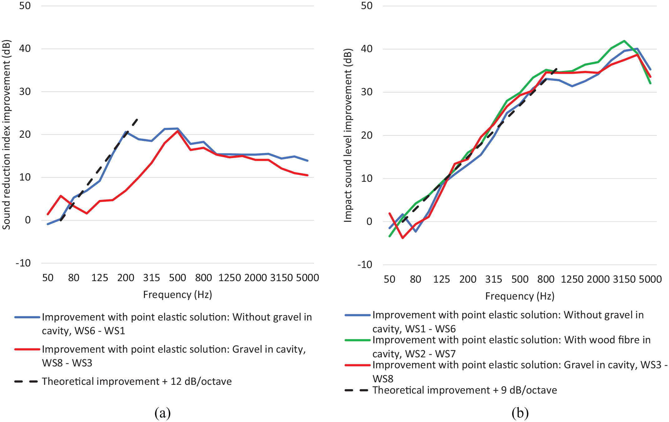
Assemblies with elastic load-bearing units: Improvement due to different materials in the cavity: (a) left: sound reduction index and (b) right: normalised impact sound pressure level.
Improvement of the airborne sound insulation
As expected, the point elastic top floor solution shows a significant improvement in the airborne sound insulation. For assemblies without gravel in the cavity, the measured frequency when the improvement starts seems to coincide with the calculated result, approximately 70 Hz, based on the equation for a double-wall resonance system (chipboard layer and upper Kerto layer) calculated according to the following equation 13 :
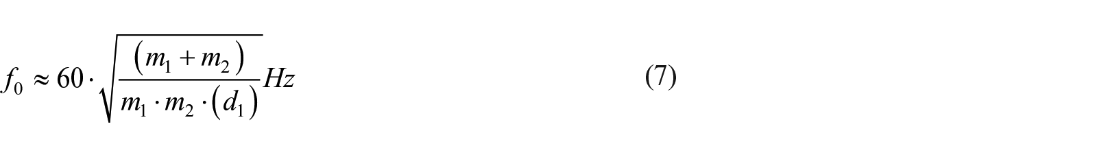
where m1 and m2 are the mass per unit area of the two upper leaves and d1 is the depth of the upper cavity.
The slope of the improvement from the measured data corresponds to the calculated improvement of 12 dB/octave according to equation (5). The improvement is limited at higher frequencies in a similar way to the continuously elastic top floor solution shown in Figure 7.
Applying the equation to a triple-wall resonance system, both solutions show the lowest estimate of fo of 20–25 Hz. This is outside the measurement range and is therefore not possible to verify. The influence on the improvement curve for the configuration with gravel in the cavity is therefore difficult to analyse. The improvement resulting from the measurement data is closer to 9 dB/octave and not as steep as the predicted 12 dB/octave.
Improvement of impact sound insulation
All measurement results for the point elastic top floor solution show the same trend in the frequency domain. We observe a frequency shift of the start position of this improvement between 63 and 80 Hz. Accordingly, the impact sound insulation improvement varies in this frequency range. Calculations according to (4) show a resonance frequency, fo, of ~74 Hz for the object without gravel and ~71 Hz for the object with gravel in the cavity. The slope of the improvement for all measurement examples coincides with an analytical calculated curve of 9 dB/octave, which is a simplification of the following equation 13 :
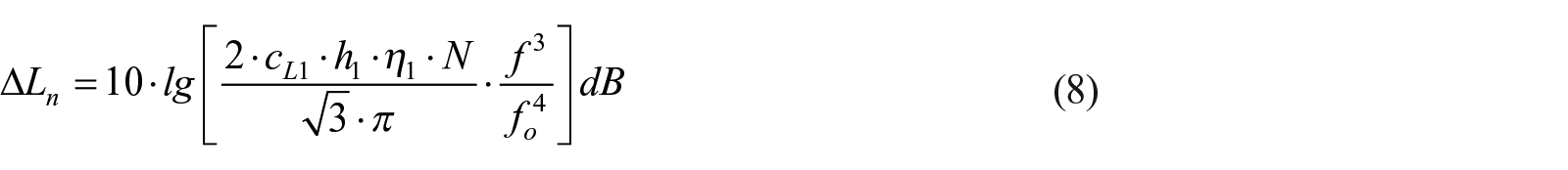
where h1, cL1 and
Comparison of continuously elastic and point elastic top floor solutions
In Figure 9, we present the reduction of the impact sound pressure level obtained by installing a lightweight floating floor on a continuous elastic layer and on elastic load-bearing units on the bare floor with gravel in the cavity, that is, Ln (WS-3)–Ln (WS-4) and Ln (WS-3)–Ln (WS-8). The compilation covers both airborne and impact sound insulation improvements. Achieved improvement of the standardised single number quantities and average improvement in the frequency range from 50 to 400 Hz are shown in Table 5. The last term is included because for lightweight floor constructions, this frequency range almost always determines the single number quantity L’n,w + CI,50–2500.
Improvement with floating floors on continuously elastic layer versus elastic load-bearing units.
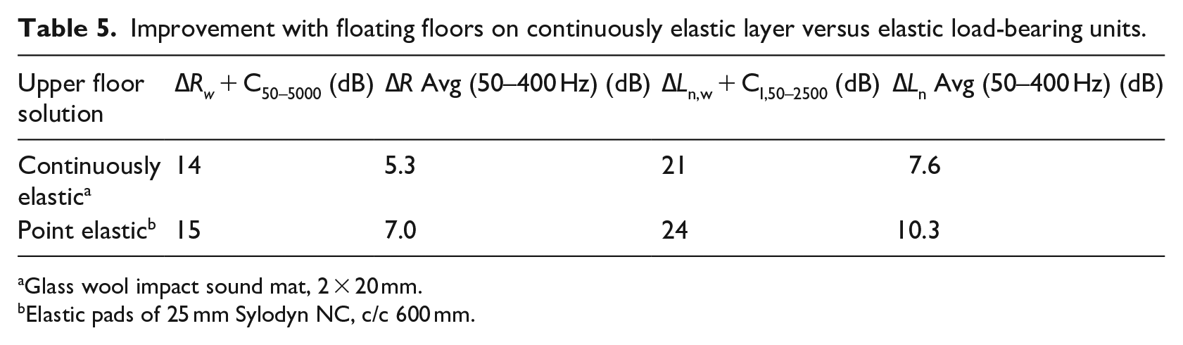
Glass wool impact sound mat, 2 × 20 mm.
Elastic pads of 25 mm Sylodyn NC, c/c 600 mm.
Comparison of the sound insulation improvement with floating floors on continuously elastic layer versus elastic load-bearing units: (a) left: sound reduction index and (b) right: normalised impact sound level.
The continuously elastic and point elastic top floor solutions show approximately the same improvement for single number quantities of airborne and impact sound insulation. The improvement for the assembly with elastic load-bearing units starts at slightly lower frequencies compared to the continuously elastic layer. The difference becomes apparent when looking at the average improvement level between 50 and 400 Hz.
Equations (5) and (6) predict with reasonable agreement the improvement of airborne and impact sound insulation as shown in Figure 8. The point elastic solutions with gravel in the cavity perform close to 12 dB/octave regarding the impact sound insulation improvement. The corresponding equation (8) underestimates the improvement, suggesting a slope of 9 dB/octave. This is probably due to the high stiffness and relatively high mass of the bare floor element with gravel in the cavity. Regarding the single number quantities with spectrum adaptation term included, the improvement of the point elastic top floor is 1 dB better for the airborne sound insulation and 3 dB better for the impact sound insulation compared to a continuously elastic top floor.
Effect of floor covering (vinyl)
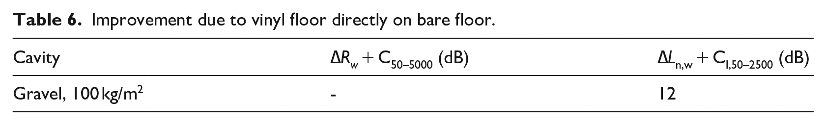
In Figure 10, we present the measured reduction of the impact sound pressure level due to a vinyl floor covering installed directly on the bare floor with gravel in the cavity (WS-3 to WS-9). For comparison, in the same figure we show the improvement measured when installing the same vinyl flooring on a concrete floor, data from Tarkett France 14 measured according to ISO 10140-5. 15 The achieved single number quality improvement is presented in Table 6.
Improvement due to vinyl floor directly on bare floor.
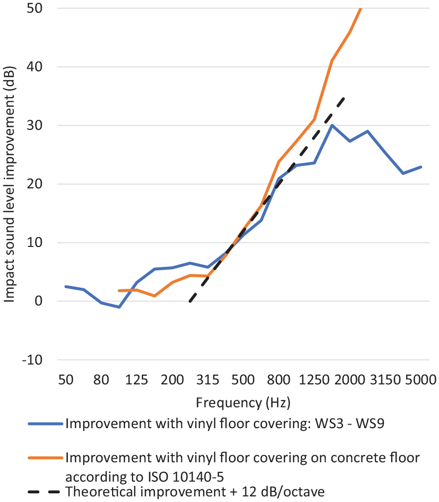
Vinyl floor covering on timber hollow-box floor element and concrete element. Impact sound insulation improvement.
The impact sound insulation improvement of this type of floor covering shows a typical slope of 12 dB/octave from a resonance frequency determined by the elasticity of the vinyl layer. Predictions are possible according to Vigran 13 ; see also Table 7. As expected, lower mass and stiffness of the subfloor limit the improvement, especially towards higher frequencies compared to a 140 mm concrete floor construction (reference floor structure). However, from these measurements, the improvement curve coincides relatively well in the frequency range below 1000 Hz. Towards higher frequencies, the improvement drops off, mainly due to the decay in the impact sound insulation curve above approximately 500 Hz of the Woodsol floor element, as shown in Figure 3.
Impact sound insulation improvements on hollow-box timber floor.
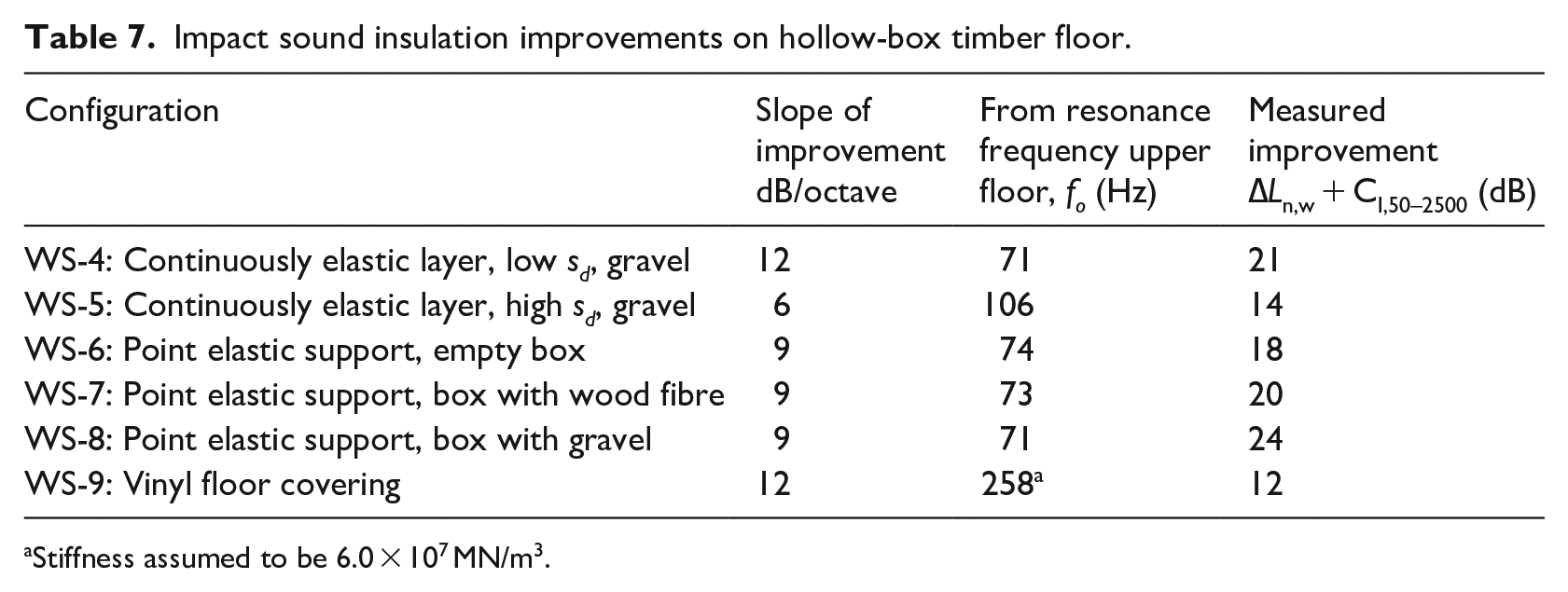
Stiffness assumed to be 6.0 × 10⁷ MN/m3.
Impact sound insulation improvement: Summary
In Table 7, we present a compact summary of the predicted impact sound insulation improvements for the different Woodsol solutions discussed above. As mentioned in sections 5.1 to 5.4, the equations are from Vigran. 13 Similar or identical equations are also available in other textbooks.
There are two major parameters governing the improvement with a continuously elastic layer: the dynamic stiffness of the resilient layer, and the impedance difference between the bare floor and the elastic top floor solution. A heavy bare floor leads to better results with the same top floor solution compared to a light one. The impedance influence also applies to solutions with point elastic support (WS-6/7/8).
Conclusion
In this paper, we presented the results of sound reduction and impact sound pressure level measurements performed in the laboratory on lightweight floating floor assemblies installed on hollow-box timber floors. The measurements included a lightweight floating floor on a continuous elastic layer with high and low dynamic stiffness, a lightweight floating floor on elastic load-bearing units and a simple vinyl covering of the bare floor. The floating floor assemblies were combined with three variants of the bare floor: empty cavity, additional mass (gravel) installed in the cavity and cavity filled with sound-absorbing material (wood fibre).
The results show that it is possible to achieve airborne and sound insulation ranging from Rw = 35 dB, Ln,w = 85 dB for the bare floor with empty cavity to Rw = 61 dB, Ln,w = 50 dB for the lightweight floating floor on elastic load-bearing units installed on the bare floor with gravel in the cavity. Therefore, the results show that hollow-box timber floors can be successfully combined with different lightweight floating floor solutions that can fulfil the acoustic requirements for a wide range of urban buildings, including for commercial, educational and residential purposes.
The analysis of the improvements showed that it is possible to predict the performance of different floor assemblies by using well-known formulas. Such predictions are generally reliable between the resonance frequency (typically around 50–100 Hz) and up to approximately 500 Hz. Key parameters are the resonance frequency of the system, determined by the mass per unit area of the bare floor and of the floating floor and the dynamic stiffness of the resilient layer as well as the configuration of the elastic layer (continuous or point elastic elements). As for massive bare floors, solutions based on elastic load-bearing units are more effective than solutions based on continuous elastic layers.
Footnotes
Declaration of Conflicting Interests
The author(s) declared no potential conflicts of interest with respect to the research, authorship, and/or publication of this article.
Funding
The author(s) disclosed receipt of the following financial support for the research, authorship, and/or publication of this article: The Woodsol project was funded by the Research Council of Norway and led by Kjell Arne Malo at NTNU. The project included research at NTNU and SINTEF Community and the PhD grant for the second author of this paper, which is gratefully acknowledged. Petra Rüther at SINTEF was work package leader for ‘WP6 Prototype’, which made the construction of the floor elements possible. Sveinung Nesheim (NTNU/SINTEF) and Aivars Vilguts (NTNU) contributed to the design and construction of the floor elements. Leif Joar Lassesen and students from the Charlottenlund Videregående skole in Trondheim (NO) built the bare floor. The measurements were performed at the SINTEF acoustic laboratory in Oslo. The laboratory fulfils the relevant requirements according to NS EN ISO 17025 and has a Norsk akkreditering NA Test 107 certification. The laboratory team at SINTEF Community in Oslo supported us when taking the measurements.