
Abstract
Low-frequency radiated noise, characterized by a distinctive “acoustic fingerprint” is generated when vibrations from marine machinery propagate through a ship’s hull into the ocean. This type of noise travels long distances with concentrated and stable energy, posing a significant threat to a ship’s acoustic stealth capabilities. Active-passive hybrid isolation is the primary method for reducing low-frequency radiated noise from ships; however, technical challenges remain, such as effectively integrating active and passive components, achieving high output force in a compact design, and addressing the poor linearity of actuator output at low frequencies. To address these issues, this paper presented an innovative electromagnetic-hydraulic-rubber integrated vibration isolator. Firstly, the study analyzed the dynamic characteristics of a two-degree-of-freedom isolation system and investigated the influence of active-passive hybrid vibration isolator parameters on control force and vibration reduction performance. Secondly, it was established that the magnetic circuit model and magnetic field strength expressions for the electromagnetic actuator using magnetic circuit analysis derive the analytical relationship between electromagnetic force, current amplitude, and frequency using the energy method. Subsequently, a mathematical model was developed for the rubber-hydraulic suspension component to examine its dynamic characteristics, hydraulic damping, and hydraulic force amplification transmission laws. Lastly, we organically combine the electromagnetic actuator with the rubber-hydraulic suspension and conduct a multi-physics joint simulation of the integrated vibration isolator using Comsol software to verify the effectiveness of the optimized design and vibration isolation control. Experimental research was carried out on the dynamic characteristics, output force properties, and fatigue characteristics of the integrated vibration isolator prototype. Results indicated that the established models and methods can achieve over 90% accuracy in predicting the performance of the electromagnetic actuator’s output force and exhibit good linearity within the 5–400 Hz range. The rubber-hydraulic suspension can achieve an amplification factor of up to 1.5 for the electromagnetic force while reducing the transmission of vibrations to the base. The research findings can enhance the low-frequency vibration isolation performance of marine machinery equipment and improve their acoustic stealth capabilities.
Keywords
Introduction
Low-frequency line spectra of ship radiated underwater noise are mainly caused by the periodic operation of electromechanical equipment. This type of noise possesses stable energy, long transmission distance, and is challenging to eliminate, serving as a primary characteristic signal for enemy sonar detection, tracking, and target identification. 1 In recent years, both domestic and international scholars have adopted various control measures to address the low-frequency vibration problems of marine machinery equipment, such as the extensive use of raft isolation, exploration of active vibration absorption, and research on active isolation technologies. 2 These measures have yielded satisfactory results, particularly the significant reduction of vibration transmission through raft isolation. However, the low-frequency vibration problem of marine machinery equipment remains a pressing issue. Although raft isolation can attenuate the transmission of low-frequency vibrations, it is unable to eliminate them entirely. Moreover, some equipment is laid out in a dispersed manner, rendering raft isolation measures inapplicable. Active vibration absorption technology, in theory, can counteract low-frequency vibrations of the equipment; however, it serves as a stopgap measure that occupies limited ship space and consumes valuable energy resources. Active-passive hybrid isolation technology introduces a secondary vibration source based on passive isolation. The controller collects the vibration characteristic signals of the controlled system and generates control signals according to specific control laws and algorithms. These control signals are output to actuators, producing active control forces that counteract the original vibration signals, thereby achieving vibration reduction and noise attenuation. 3 The rapid advancement of digital signal processing, intelligent control, and deep learning technologies has provided various possibilities for the implementation of active isolation, leading to its wide application in aerospace, vehicle engineering, precision instruments, and marine machinery fields. Research on integrated active-passive isolators conducted by scholars globally focuses on two aspects: firstly, the application of novel materials, such as electromagnetic rheological materials, magnetostrictive materials, and shape memory alloys in isolators, which improve output force characteristics and reduce the impact of output force nonlinearity on the control system through material properties; secondly, the optimization of structural design, which involves enhancing the generation and output methods of output force, increasing output force per unit volume, and improving the coordination between different actuators and passive components. 4
The concept of active control can be traced back to 1930 when American scientists introduced a patent for utilizing an active sound source to suppress interference within pipelines, ultimately leading to the elimination of noise. 5 During the 1950s, American scholars began to explore the feasibility and implementation of active control technology, with a predominant focus on high-end applications. 6 From the early 1970s through the mid-1980s, there was significant development in active vibration control technology, which gradually expanded its applications to various domains, including ships, vehicles, and precision machine tools. 7 Subsequently, beginning in the late 1980s, due to the maturation and reliability of electronic control components, sensors, actuators, and control theories, active vibration and noise control technology experienced rapid advancement. It transitioned from theoretical research into practical applications, addressing scenarios such as space flexible bodies, high-rise buildings, automobiles, and ships. 8 In the realm of transportation engineering, active vibration isolation primarily focuses on the engine section to minimize the impact of powertrain vibrations on occupants and enhance the overall driving experience. Within the domain of ship engineering, active vibration isolation techniques are mainly applied to mitigate the vibrations originating from power devices like diesel engines. In aviation, active vibration isolation plays a crucial role in countering vibrations experienced under microgravity conditions and ensuring that external vibrations remain within acceptable limits for experiments. In civil engineering, active vibration isolation finds its primary use in safeguarding massive, flexible engineering structures against seismic forces. Notably, the active vibration control system deployed in the American Sea Wolf-class nuclear submarine has demonstrated outstanding acoustic stealth performance. 9 Furthermore, researchers like Sakamoto from Kawasaki Heavy Industries in Japan have made notable advancements by substituting hydraulic servo mechanisms with electromagnetic active actuators in the study of active vibration isolation for diesel generator sets, yielding substantial research outcomes. 10 Moreover, the United States has employed active noise and vibration control systems developed using maritime high-speed network technology. These systems have proven highly effective in isolating low-frequency vibrations (not exceeding 100 Hz) generated by the entire boat’s equipment. 11
As the executive mechanism and a crucial component of the active-passive integrated vibration isolator, the actuator serves the purpose of converting non-mechanical quantities, such as electrical signals generated by the controller, into mechanical quantities like strain, displacement, and force. 12 This transformation enables the actuator to execute strain-driven, displacement-driven, and force-driven actions on the controlled object. Currently, several types of actuators find widespread application, each possessing distinct characteristics that make them suitable for specific scenarios. These actuator types include electrostrictive, magnetorheological, hydraulic, pneumatic, and electromagnetic actuators. Their primary distinctions lie in terms of output force, displacement, and response speed, which determine their suitability for various applications. 13 Piezoelectric actuators, characterized by rapid response times, are well-suited for scenarios with flexible shells. However, they typically offer limited displacement and force capabilities. Electrostrictive ceramic actuators are ideal for situations requiring small displacements, substantial forces, and swift responses. Magnetorheological actuators, known for their rapid response and substantial output force, are frequently employed in the design of active damping structures. Hydraulic and pneumatic actuators excel in delivering substantial output forces but are associated with larger physical dimensions and weight. They are commonly utilized in controlling stationary systems such as civil structures. Electromagnetic actuators exhibit linear output characteristics within specific frequency bands, ensuring swift response times and exceptional controllability. This versatility allows them to effectively meet the practical engineering demands of active vibration isolation devices.
In conclusion, current research on active vibration isolation both domestically and internationally mainly focuses on large-scale equipment such as marine diesel engines and main generator sets. However, most studies remain at the experimental validation stage, with limited practical engineering applications. Owing to the complex and harsh working conditions of marine machinery equipment, as well as stringent space and power constraints, the widespread implementation of active vibration absorption technologies and active vibration isolation technologies, which employ airbags as passive isolation components, face challenges when installed and operated in marine machinery equipment with confined spaces. Furthermore, although active vibration isolation technology merges the benefits of passive isolation and active control, the system design still grapples with essential issues, including the effective integration of active and passive components, the achievement of substantial output force within a small volume, and addressing the poor linearity of actuator output at low frequencies. Consequently, research and application of active vibration isolation devices tailored for marine machinery equipment are still scarce.
To address these concerns, this study targeted the vibration characteristics of marine machinery equipment, aiming to develop low-frequency active vibration isolation technology that is compatible with real-ship applications. The research prioritized the investigation of high output force density linearized electromagnetic actuators and rubber-hydraulic suspensions capable of delivering passive vibration isolation effects while being coupled with the actuators. By integrating rubber-hydraulic suspension models with electromagnetic actuator models, the structure of a comprehensive electromagnetic-hydraulic-rubber vibration isolation device is optimized. Utilizing the Comsol simulation software, multi-physics joint simulations are conducted to validate the optimization design and its vibration control effects. Additionally, experimental research explores the dynamic characteristics, output force properties, and fatigue performance of the prototype.
Working principle and structural design of hybrid active-passive vibration isolators
Working principle of hybrid active-passive vibration isolators
To tackle the issue of low-frequency vibration control in marine power machinery systems, an adaptive active control approach is incorporated into a two-degree-of-freedom vibration isolation framework. The detailed schematic representation can be found in Figure 1. Schematic of the two-degree-of-freedom active isolation system.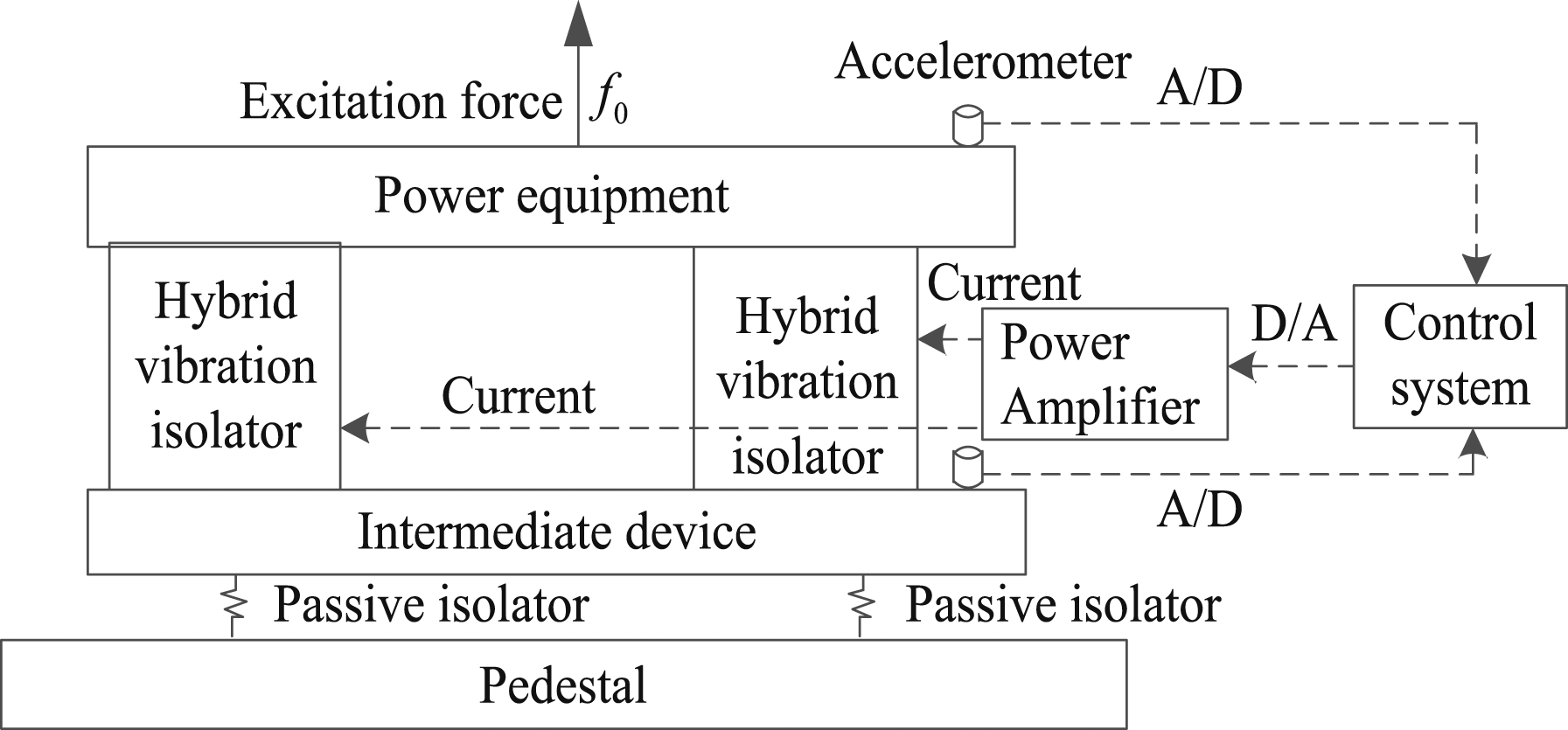
The primary components of the two-degree-of-freedom active vibration isolation system include a hybrid isolator, an accelerometer, a hardware control system, and a power amplifier. The hardware system is responsible for signal acquisition, processing, and output generation. The operational principle of this system is as follows: The accelerometer captures acceleration signals from both the upper and middle layers, which serve as reference and error signals for the control system. These signals undergo analog-to-digital (A/D) conversion before being input into the controller. The control algorithm then computes the output signal, which is subsequently converted from digital-to-analog (D/A) format and sent to the power amplifier. This amplifier drives the hybrid isolator to generate a control force, effectively counteracting the low-frequency spectral vibrations produced by the power machinery.
When active control forces are not considered, the hybrid isolator can be simplified as a stiffness-damping structure. Under these conditions, the effective mass of the hybrid isolator is minimal, and the elastic component behaves as a massless spring during low-frequency vibrations. Mechanical schematic of the two-degree-of-freedom vibration isolation system.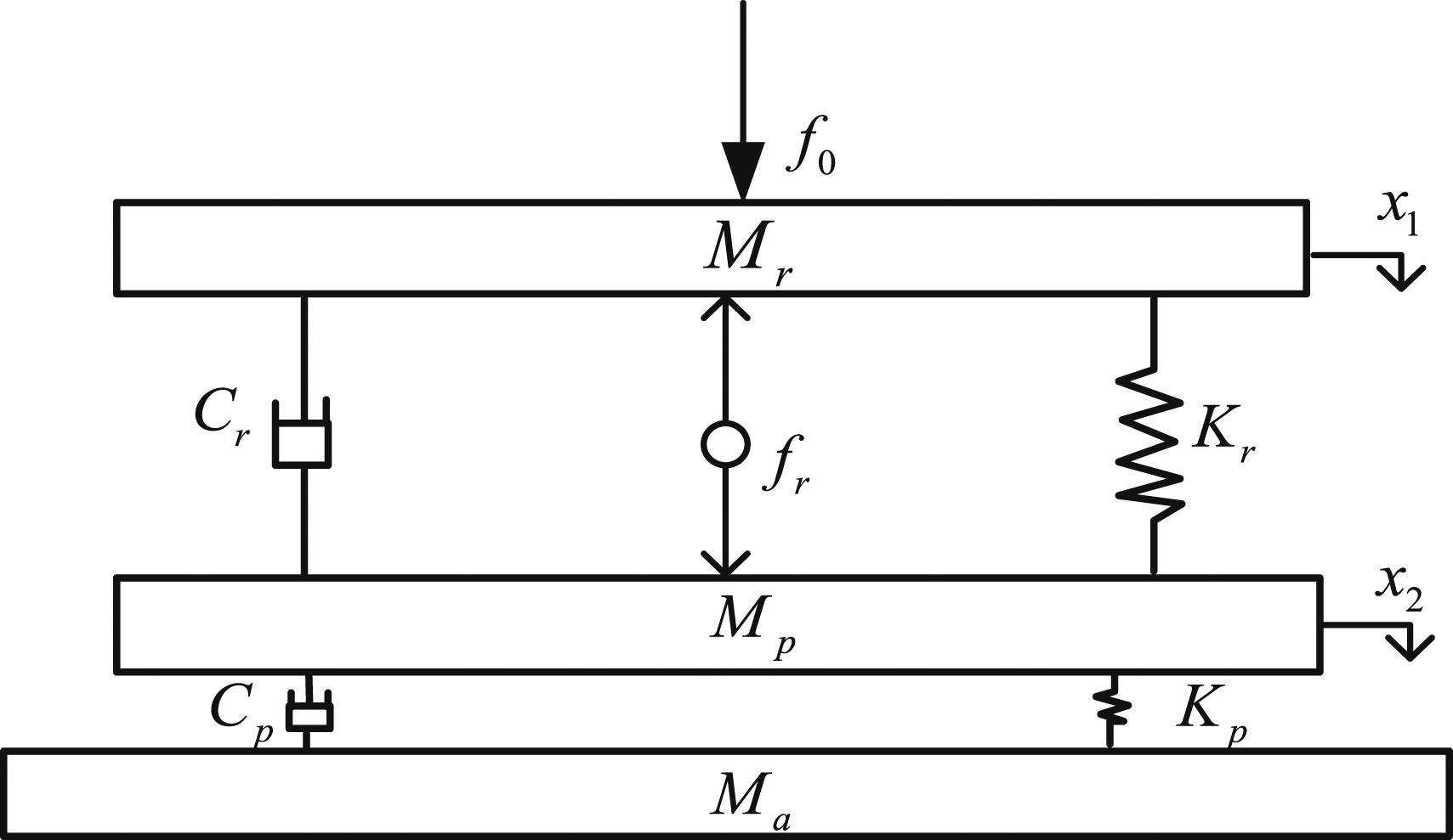
The system motion differential equation can be expressed as

In the equation, the excitation

In the equation,


Let

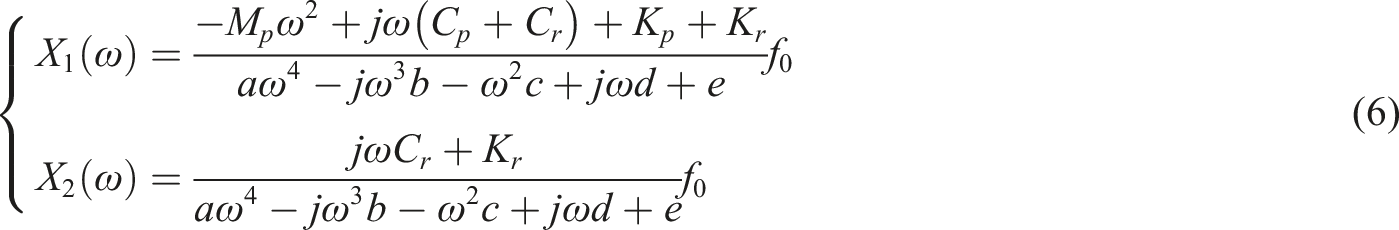
In order to analyze the influence of performance parameters on the vibration isolation effect, the force transmission rate is used as the evaluation index. For a double-layer vibration isolation system, transfer the force

The absolute force transmissibility of the isolation system at this time is expressed as

The characteristics of the excitation force amplitude are denoted by “f0 (ω)” while the force amplitude transmitted to the foundation is denoted by “f
b
(ω).” To facilitate a visual analysis of the impact of system parameters on isolation performance, we introduce the following parameters: “

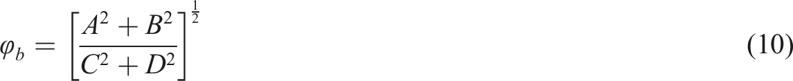
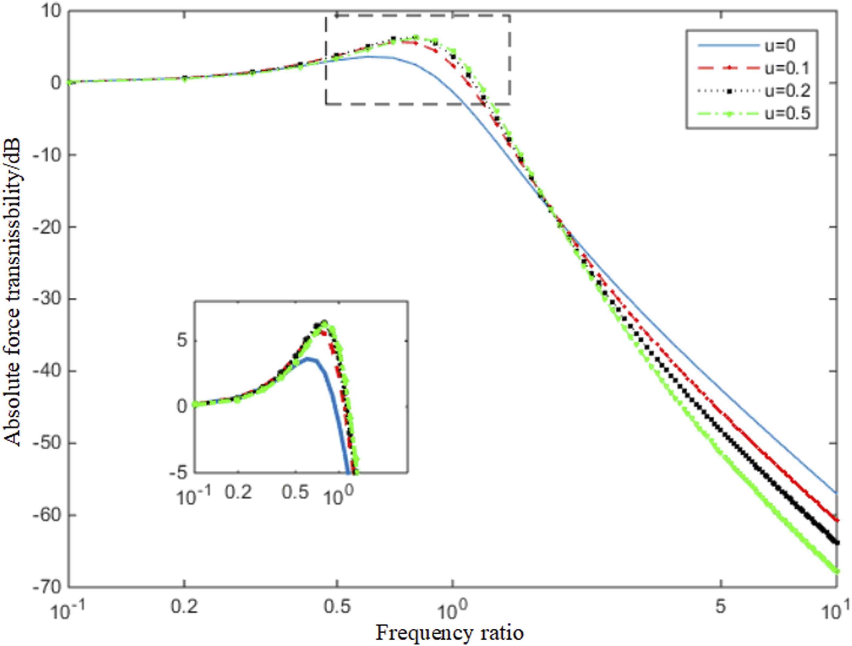
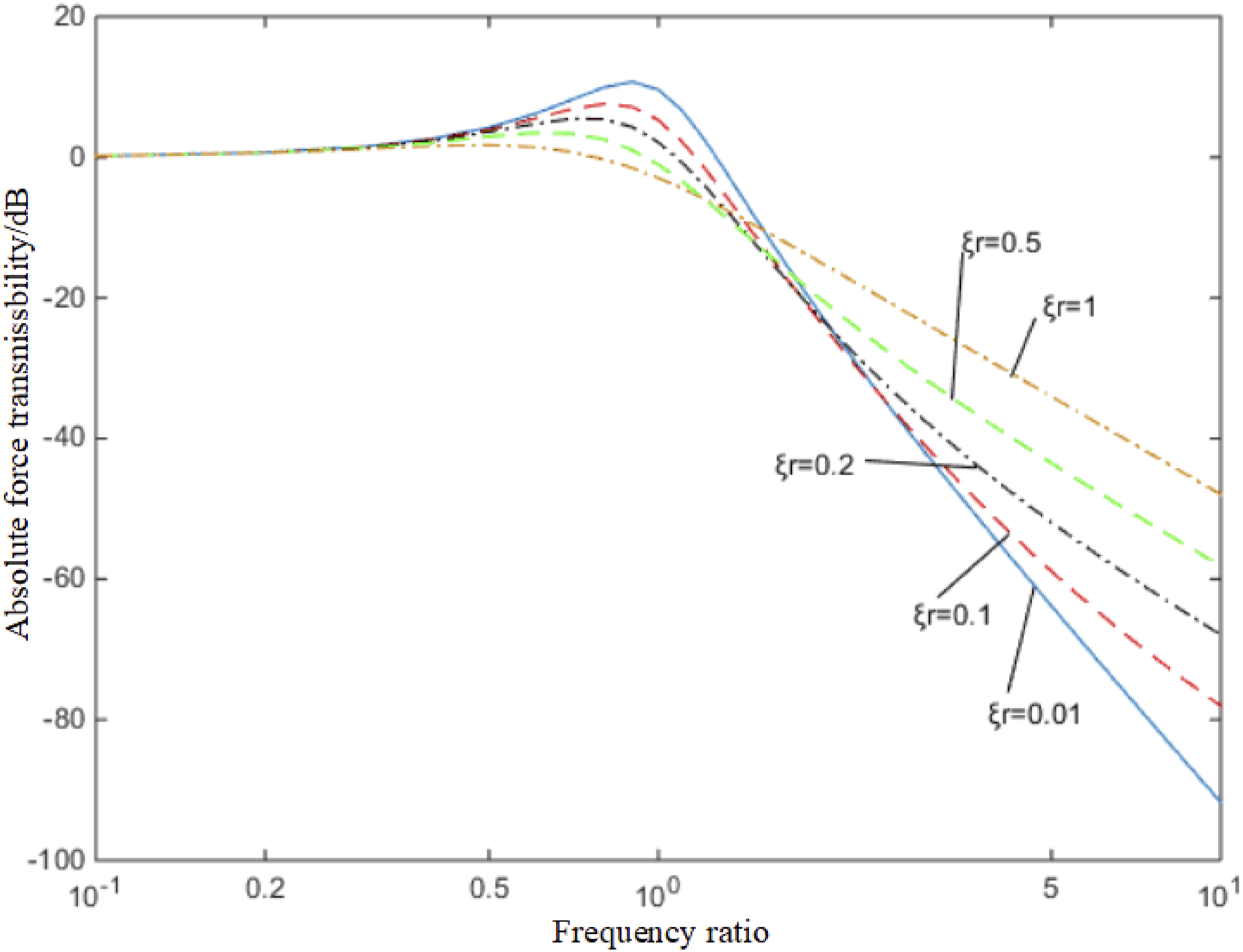
Analyzing equation (10), the curves of frequency ratio g and absolute force transmissibility under different mass ratios, as well as the curves of frequency ratio g and absolute force transmissibility under different damping ratios, are shown in Figures 3 and 4, respectively, (1) The inclusion of an intermediate mass block substantially enhances the passive vibration isolation performance under high-frequency excitation. However, it also increases the vibration amplitude near the resonance frequency. (2) The isolation effect is more pronounced when the mass ratio “u = 0.2” is coupled with the frequency ratio “ (3) When the mass ratio is fixed, the isolation effect in the frequency ratio range “ Absolute force transmissibility of double-layer isolation system under different mass ratios. Absolute force transmissibility of double-layer isolation system under different damping ratios.
After active control is turned on, the isolator produces active control force

At this time, the solution to the equation is

The amplitude-frequency characteristics of the active control force required to isolate the excitation force can be expressed as

The ratio of the active control force to the excitation force is

In order to investigate the influence of the active control force on the vibration displacement of the isolation object, an evaluation index
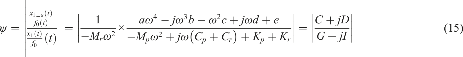
In this mechanical design paper, by analyzing equations (13) and (15), Figure 5 displays the required active control force under various damping conditions, while Figure 6 presents the situation of the origin displacement admittance ratio. Budget of required control force under different damping ratios. Ratio of front and rear displacement under different damping ratios.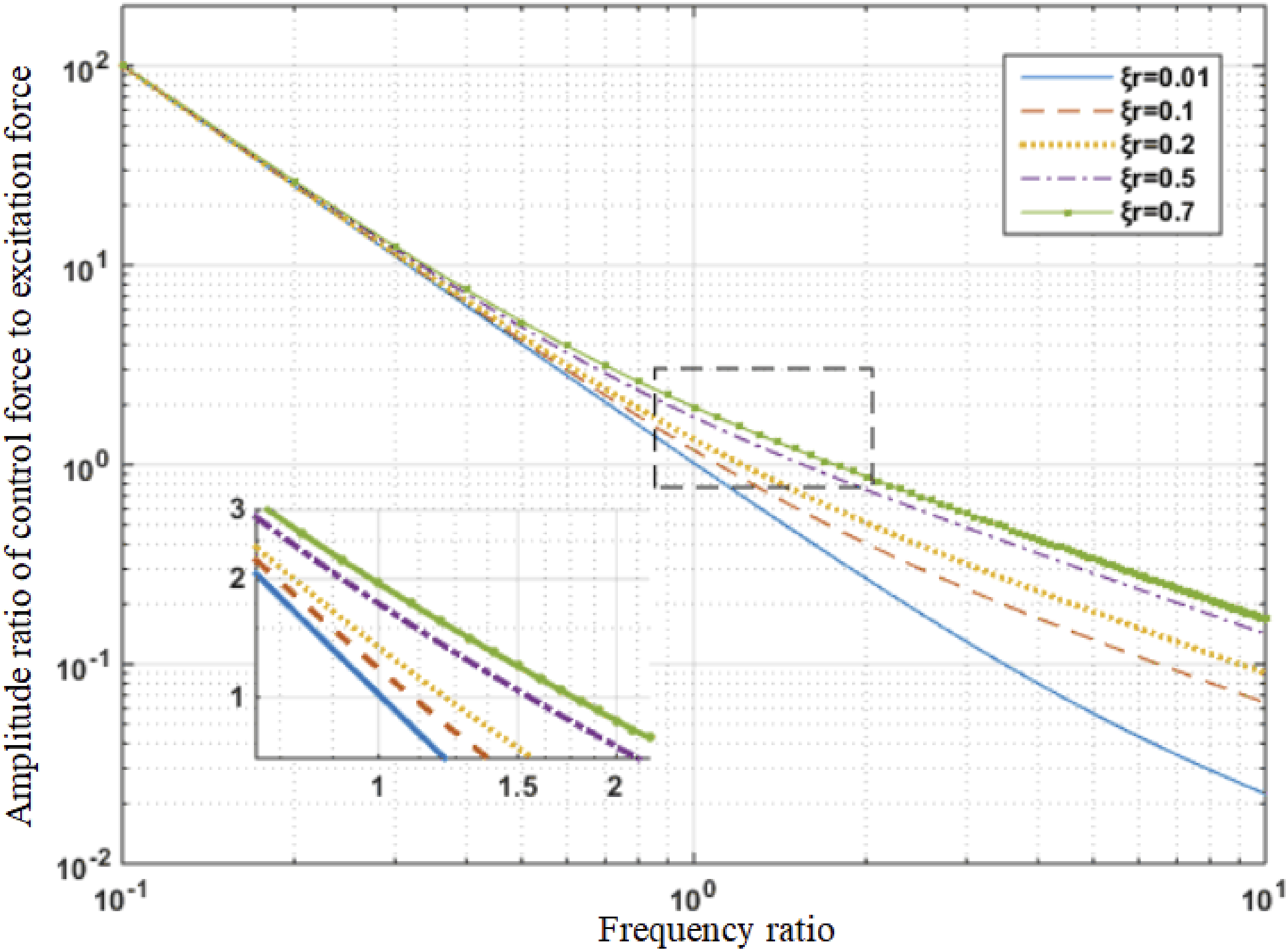
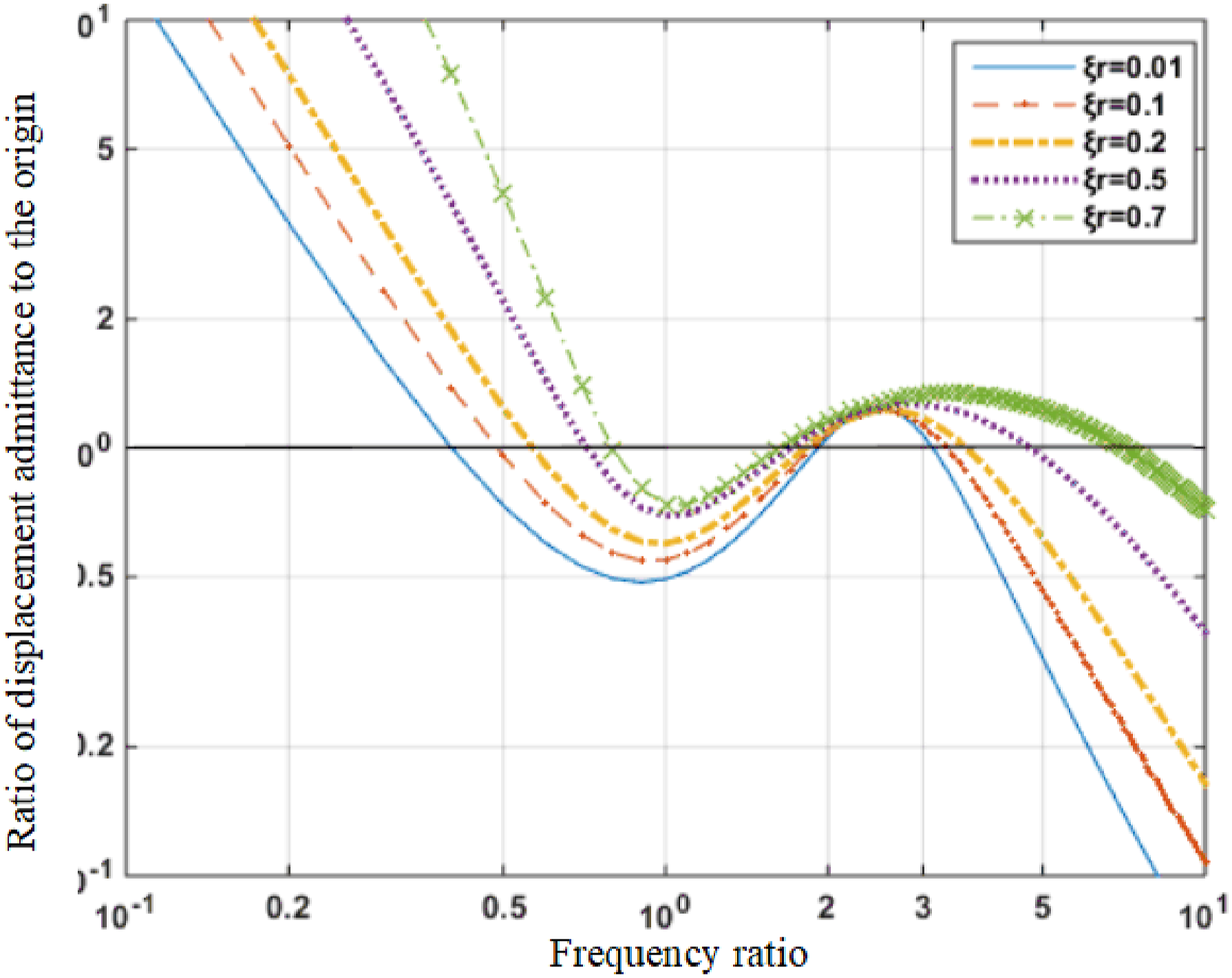
It can be seen from Figures 5 and 6 that: (1) The required active control force is greater than the excitation force for all frequency ratios (2) When the excitation force frequency and amplitude remain constant, the required active control forces increase as the damping ratio rises. (3) Active isolation reduces the vibration amplitude of the isolated object in the
Considering the influence of comprehensive performance parameters on vibration isolation performance, the two-degree-of-freedom hybrid vibration isolation system exhibits the following characteristics: (1) The introduction of the intermediate mass block improves the isolation effect of high-frequency excitation. (2) When the frequency ratio (3) The damping ratio
Structural design of active-passive integrated vibration isolator
Integrated active-passive vibration isolators typically comprise actuators and passive components interconnected in series or parallel configurations. The purpose of the actuator is to “neutralize” the vibrations transmitted from the source to the base through active vibration control algorithms, while the passive isolator functions to attenuate vibration energy in various forms. The crucial aspect of developing integrated active-passive vibration isolators lies in the innovative design of actuators and their optimal integration with passive isolators, resulting in superior vibration isolation performance. 14 However, numerous types of actuators and passive isolators currently exist: actuators include electromagnetic, piezoelectric, magneto strictive, and hydraulic drive forms, while passive isolators consist of rubber, hydraulic suspension, airbags, and metal springs. This paper adopts an electromagnetic-rubber-hydraulic integrated design concept after analyzing different combinations of actuator types and passive components, and designs a marine integrated active-passive vibration isolator using a parallel configuration of electromagnetic actuators and rubber-hydraulic passive isolation devices.
The electromagnetic-rubber-hydraulic integrated vibration isolator is simplified as a dual-input single-output system, with the inputs being the electromagnetic actuator excitation current or voltage signal Schematic diagram of the working principle of the integrated vibration isolator.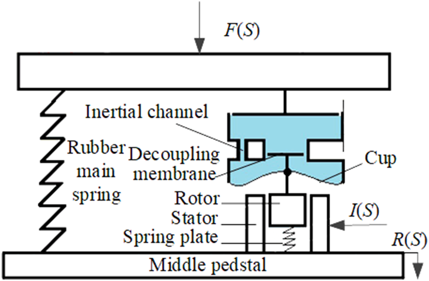
Mathematical model

Within this model,

Pa_f (S) is determined by the electromagnetic actuator’s internal structure, the working principle as shown in Figure 8. Specifically, when the coil is energized, an alternating magnetic field is generated in the stator core, which interacts with the permanent magnetic field on the rotor to produce electromagnetic force on the rotor, forming the output force of the electromagnetic actuator. When the coil is energized, the N and S poles at both ends of the stator core alternate according to the direction of the current, and they attract or repel the magnetic poles of the permanent magnet on the rotor, generating alternating axial electromagnetic force. The stator core is designed in a “C” shape, and the coil is wound axially inside the “C”-shaped core, while the permanent magnet is distributed axially at both ends of the rotor.
15
Working principle of electromagnetic actuator.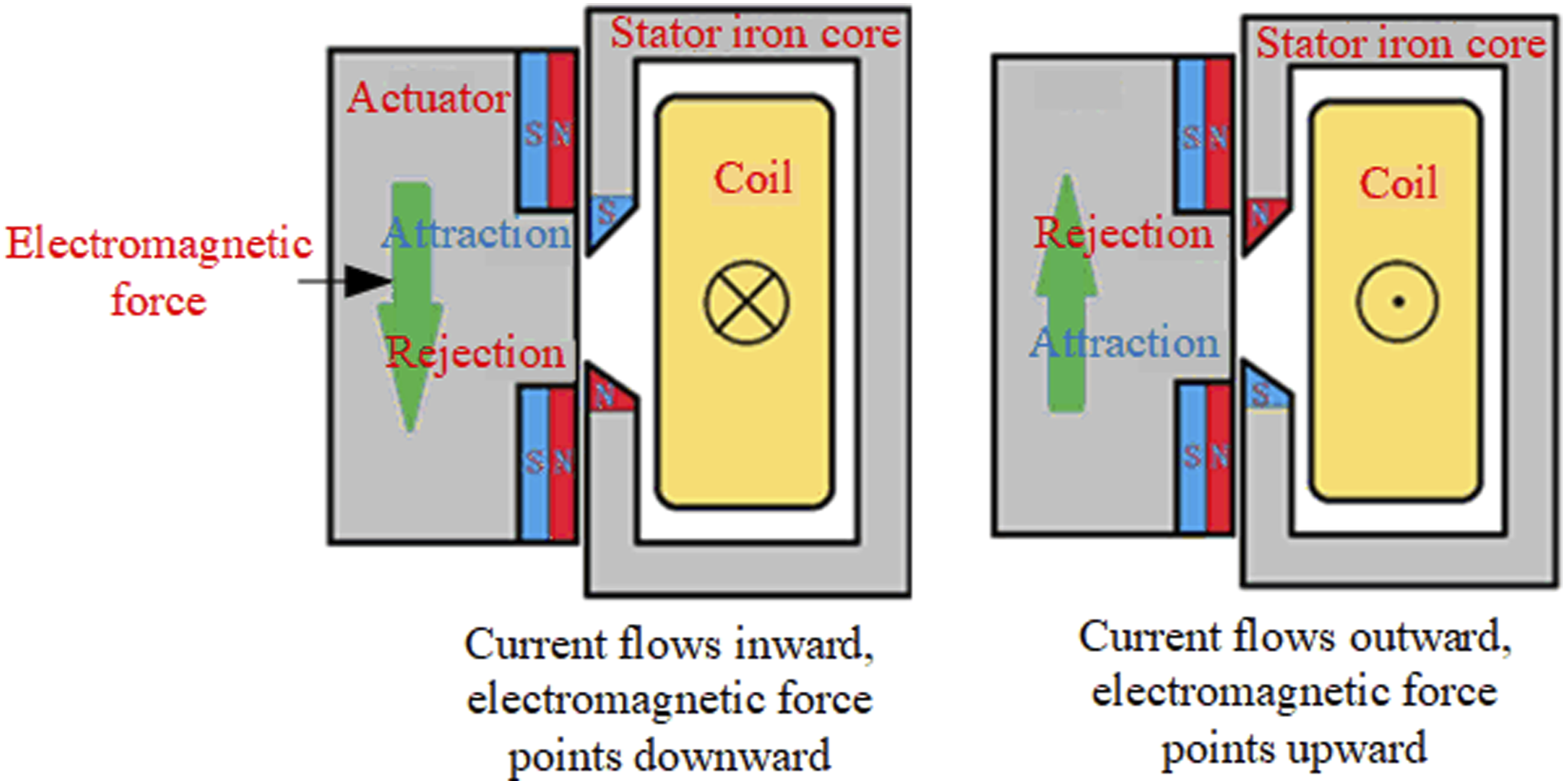
Compared with traditional electromagnetic actuators (voice coil motor actuators), the advantages of this scheme are: (1) The cost is relatively low compared to the voice coil motor actuator, as this design significantly reduces the amount of permanent magnet material required, resulting in lower costs for obtaining the same output. (2) Higher output per unit volume is achieved, as the voice coil motor is constrained by the number of layers of the barrel-shaped coil. To increase the output of the unit diameter voice coil motor, it is necessary to increase its height, whereas the output of this electromagnetic actuator is not directly related to its height. Thus, the output volume density advantage is evident in small-sized electromagnetic actuators.
The Partial structural view of hybrid isolator.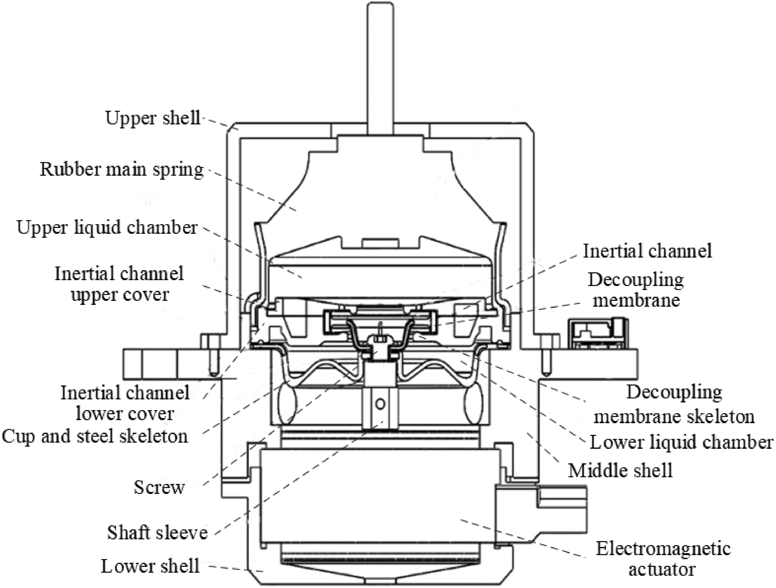
Design of electromagnetic actuation unit
To quantitatively analyze the relationship between current amplitude, frequency, and electromagnetic force, a magnetic circuit analysis of the electromagnetic actuator is conducted. This involves determining the magnetic field strength in each air gap under the influence of both alternating and direct magnetic fields, followed by computing the electromagnetic force. Figure 10 presents the primary sectional view of the electromagnetic actuator. Considering its overall axial symmetry, analyzing half of the cross-section suffices for the magnetic circuit analysis. Main sectional view of the electromagnetic actuator.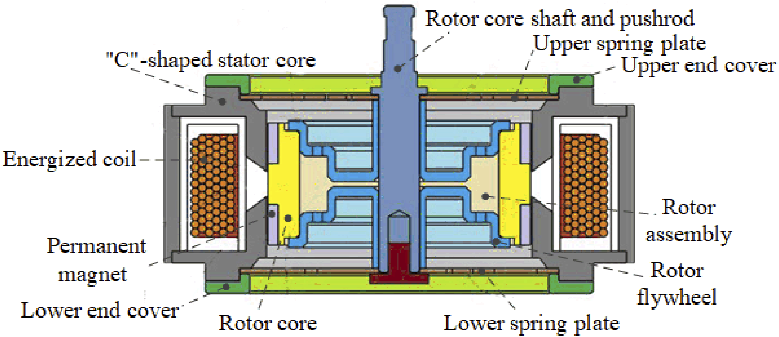
Magnetic circuit analysis of the electromagnetic actuator
The permanent magnet and energized coil within the electromagnetic actuator create distinct direct current (DC) and alternating current (AC) magnetic circuits. Figure 11 illustrates the distribution of these magnetic circuits when the coil current is oriented inward. For the upper permanent magnet, the DC magnetic circuit originates from the magnet’s north pole, with most of the magnetic flux traversing Region A. Upon entering the stator core, the flux bifurcates into two pathways: one path forms a closed loop by returning to the rotor core through Region B and eventually to the magnet’s south pole; the other path forms a closed loop by overflowing from the stator core into the ambient air before returning to the rotor core and ultimately to the magnet’s south pole. The lower permanent magnet’s DC magnetic circuit is symmetrical to the upper one. The AC magnetic circuit is comparatively simpler than the DC circuit. Assuming an inward current in the coil, an alternating magnetic flux with a clockwise direction is generated in the stator core. This flux passes through Region B′, enters the rotor core, and returns to the stator core via Region B, forming a closed loop. Schematic diagram of magnetic circuit inside the electromagnetic actuator.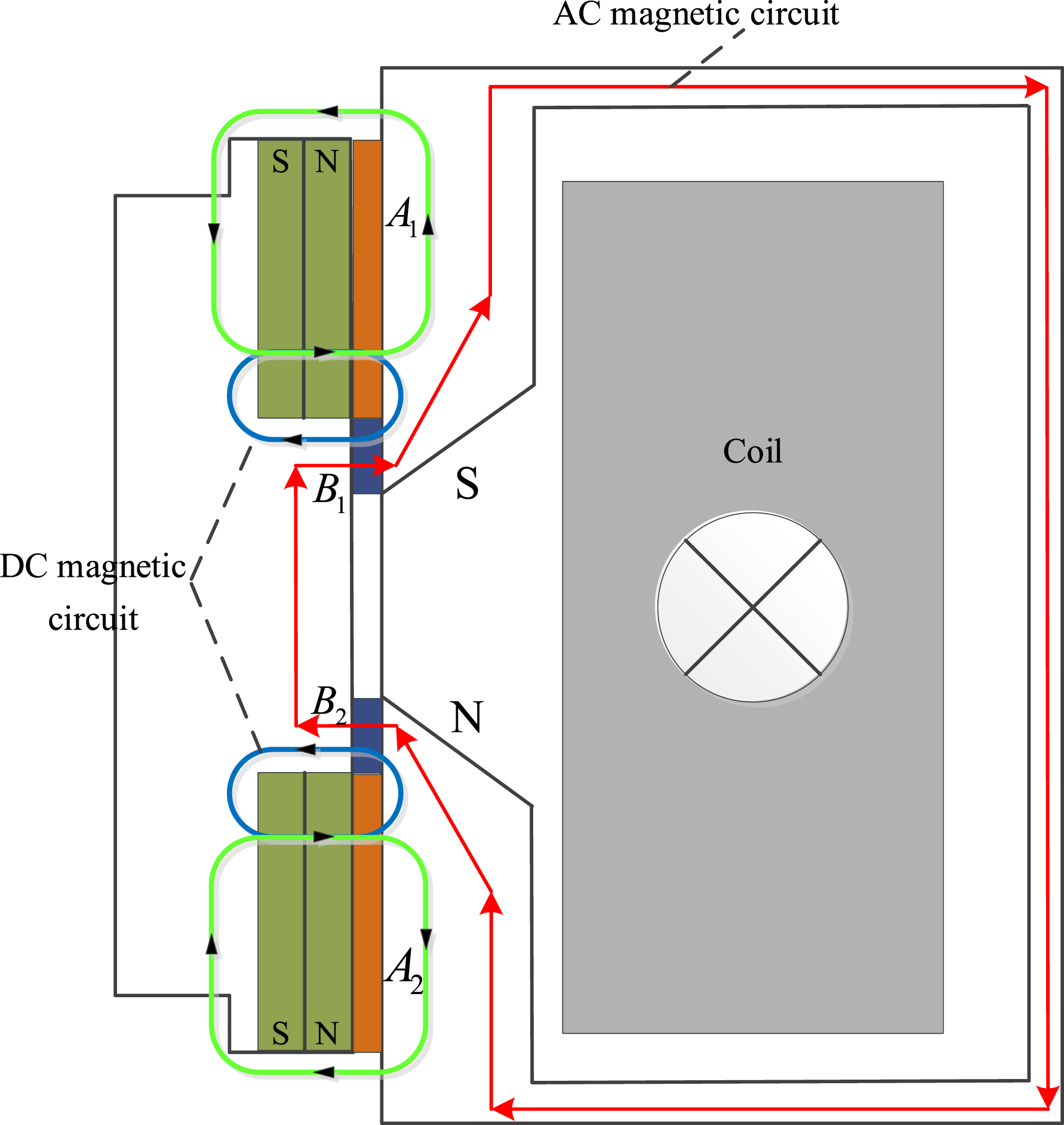
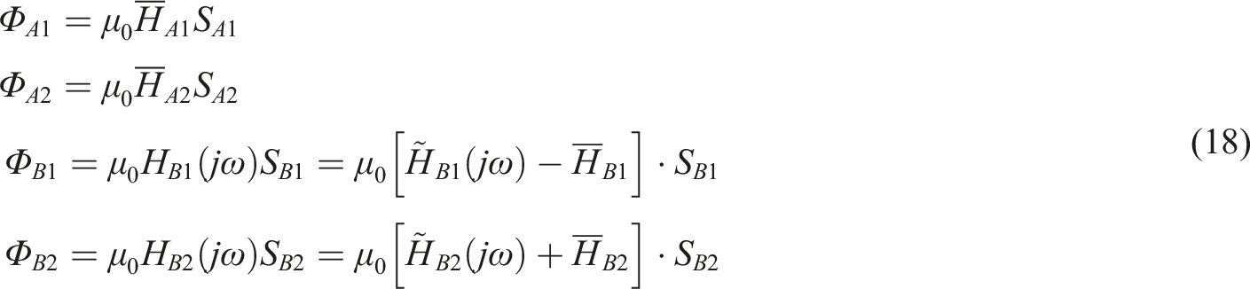
According to the characteristics of the DC and AC magnetic circuits, different magnetic flux densities are formed in different air gap regions. The air gap can be divided into four regions
First, the AC magnetic circuit is analyzed. It has good closure, and most of the magnetic flux is located inside the “C”-shaped stator core, with a small part in the air gap and rotor forming a closed loop. To simplify the magnetic circuit model, it is assumed that the AC magnetic circuit does not pass through the Simplified model of AC magnetic circuit.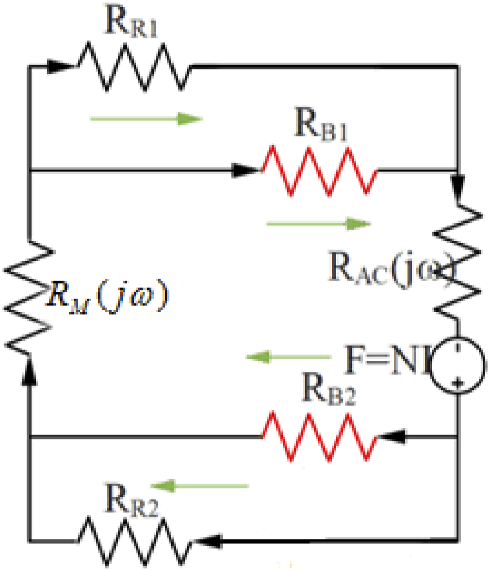
In the magnetic circuit model,
From Figure 13, it can be seen that parts Simplified diagram of magnetic cores.

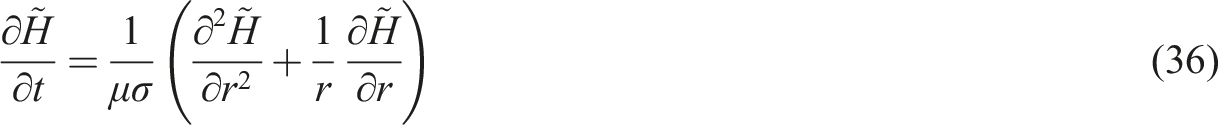
Using the separation of variables method to solve the boundary condition problem, letting

The left side of the equation does not contain t, and the right side is a function of t. Equation (20) is a typical mathematical equation problem. Assuming


The general solution


Equation (24) is a typical Bessel equation. Let


For cylindrical and disk-shaped magnetic conductors, the boundary conditions differ, so the specific solutions for the diffusion equation are discussed separately. First, for cylindrical magnetic conductors, the following boundary conditions are given
In these conditions,
The parameter values of
At this point, substituting the obtained parameters into equation (26) yields

The gain constant
The diffusion equation of magnetic field intensity in cylindrical magnetic conductor is
Similarly, the diffusion equation of magnetic field intensity in disc-shaped magnetic conductor is
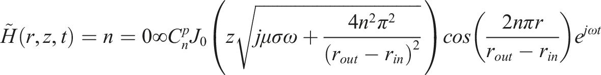
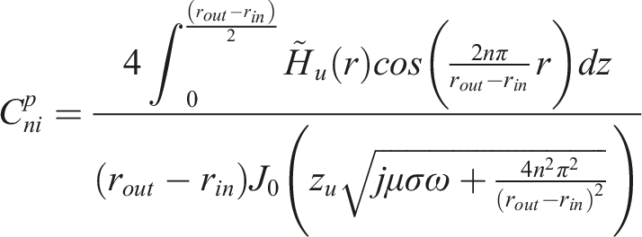
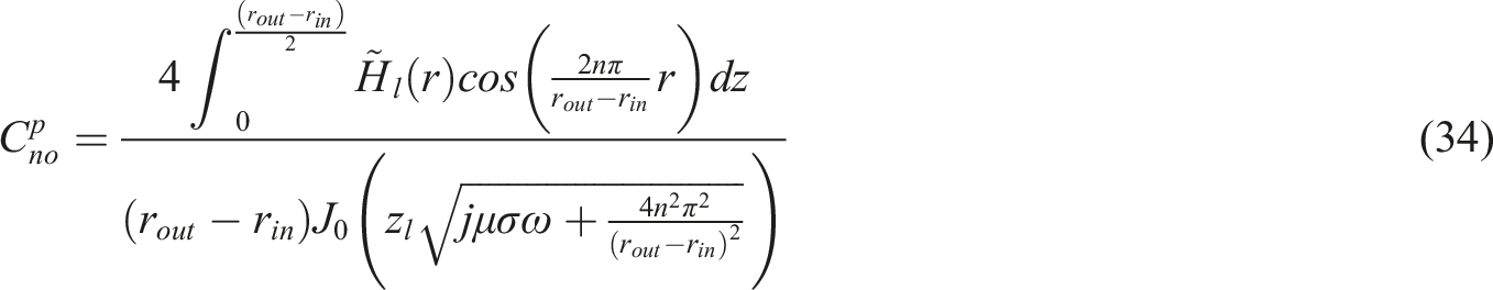
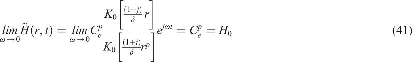
Equations (33) and (34) are the theoretical expressions for the magnetic field strength diffusion equation in cylindrical and disk-shaped magnetic conductors. However, these equations are too complicated for practical applications. To simplify the calculations, it is assumed that the magnetic field
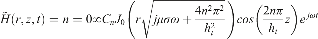
If the distribution of the AC magnetic field is independent of z, the magnetic field strength diffusion equation reduces to a one-dimensional problem, and the diffusion equation can be expressed as
The general solution of the equation obtained by the separation of variables method above is

In the equation,
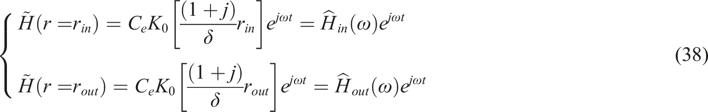
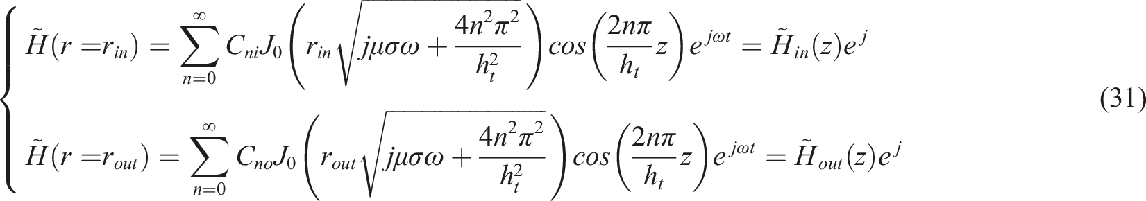
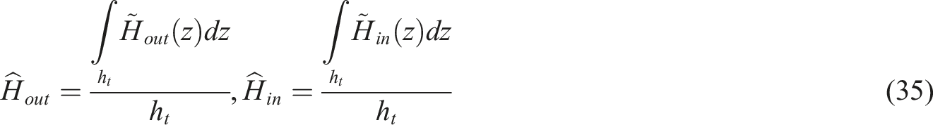
By comparing the magnetic field intensity on the outer and inner surfaces in equation (38), it can be obtained
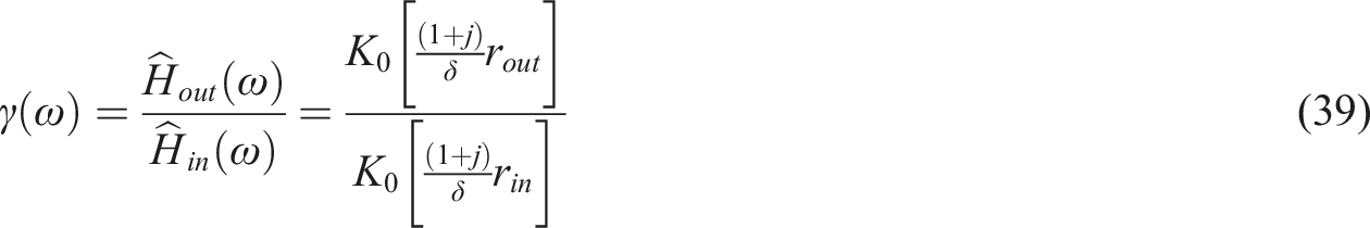
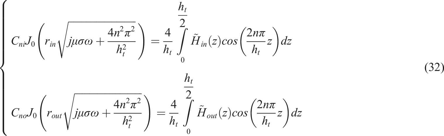
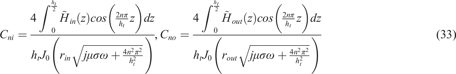
From the above equation, we can see that there is certain regularity in the distribution of the boundary magnetic field, and the ratio fluctuates with frequency. When equation (38) is abstracted as a mathematical model within a fixed interval
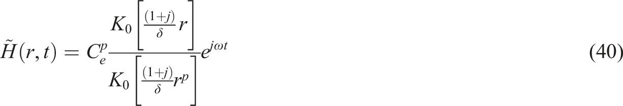
Magnetic flux is
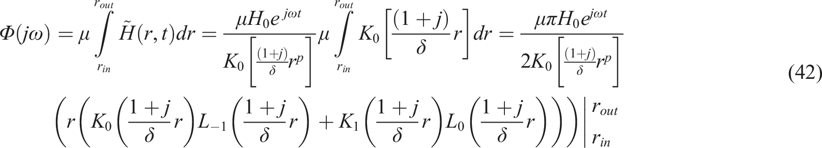
In the equations,

The AC magnetic resistance at the stator iron core is


The rotor resistance, air gap resistance, and permanent magnet resistance can be simplified by the following formula

In the formula,
The following analysis focuses on direct current (DC) magnetic circuits, with Figure 14 providing a visual representation of the DC magnetic circuit model. When compared to alternating current (AC) magnetic circuit calculations, the computation process for DC magnetic circuits proves to be more manageable. This is primarily due to the elimination of magnetic reluctance variations attributed to fluctuating frequencies. However, the primary challenge resides in accurately determining leakage flux values. In the case of AC magnetic circuits, a substantial portion of the magnetic flux forms a closed loop encircling the “C”-shaped cross-sectional stator core, which can be attributed to the superior closure properties of these circuits. Conversely, DC magnetic circuits lack closed-loop characteristics, causing a portion of the magnetic flux to disperse into the surrounding air. Additionally, the intricate geometric shape of surrounding magnetic conductors complicates the process, making it increasingly difficult to precisely calculate the volume of magnetic flux entering the air through theoretical means. Consequently, engineering practices often incorporate finite element analysis methods, which serve to identify the leakage magnetic flux of DC magnetic circuits under specific geometric dimension parameters. DC magnetic circuit model.
Using the upper half as an example, the air gap between the permanent magnet and the stator core is minimal. It can be reasonably assumed that the entire magnetic flux penetrates the stator core through region

Calculation of electromagnetic force of electromagnetic actuator
Drawing upon the magnetic circuit analysis results presented in previous section and incorporating material parameters and geometric dimensions, the magnetic reluctances of each component and the magnetic flux at the air gap can be deduced following the abstraction of the magnetic circuit. The energy analysis method is employed to perform theoretical calculations of the electromagnetic force exerted on the actuator. The comprehensive magnetic circuit’s equivalent model is illustrated in Figure 15. Comprehensive magnetic circuit equivalent model.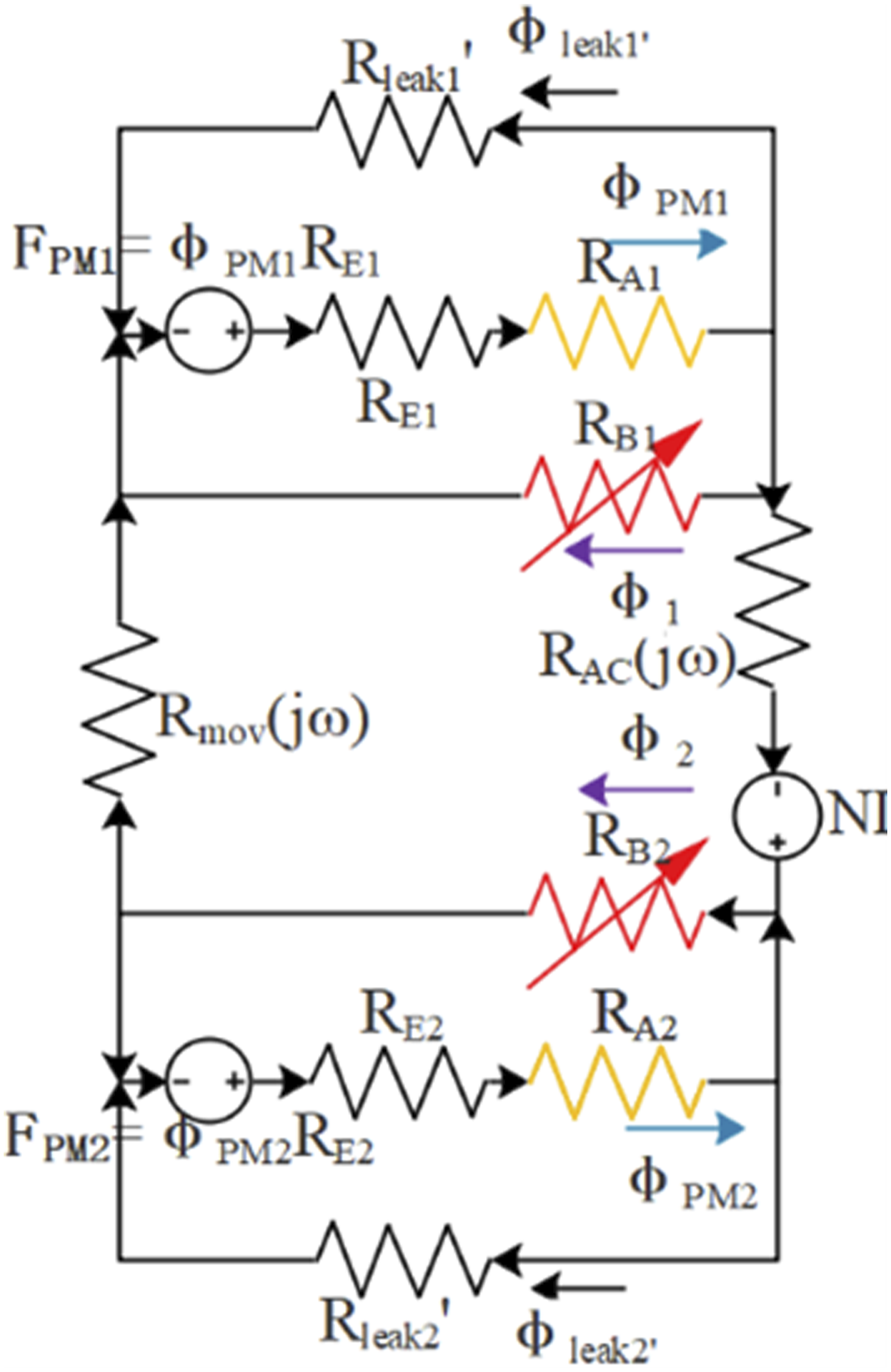
As deduced from the electromagnetic actuator’s magnetic circuit analysis, both the rotor and stator iron cores possess low magnetic reluctances due to their excellent magnetic conductivity, while the air gap exhibits a larger magnetic reluctance.
16
Most of the system’s energy is stored at the air gap. For the equivalent magnetic circuit, the total energy can be represented as


In accordance with the principle of energy conservation, it is assumed that the negative partial derivative of the total energy in the Z direction corresponds to the electromagnetic force of the actuator in the Z direction, expressed as

Substituting equation (50) into equation (51) yields

When the actuator is energized, the rotor oscillates around the equilibrium position, necessitating a correction to the magnetic reluctance of the air gap in region B
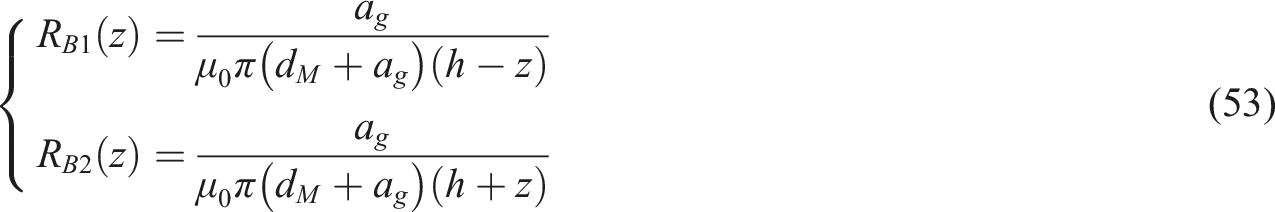
Substituting equation (53) into equation (52), the following equation obtained

When the rotor displacement z is small,

By substituting equations (47) and (48) into equation (55), the formula for the electromagnetic force exerted by the electromagnetic actuator is obtained as

As evident from equation (56), the electromagnetic force
Finite element simulation of electromagnetic actuator
Comsol, a powerful finite element analysis software, boasts multiple physics field analysis modules, including electromagnetics, thermodynamics, structural mechanics, electrochemistry, plasma, and more. It also features built-in multi-physics coupling modules, facilitating structural modeling, mesh generation, excitation current application, and solution finding. The AC/DC module employs the Maxwell stress tensor method for calculating electromagnetic forces, enabling intuitive visualization of amplitude-electromagnetic force curves and frequency-electromagnetic force curves. The specific steps for finite element simulation analysis are: (1) Based on the characteristic analysis and existing experience, determine the specific materials and dimensional parameters for each part of the actuator; (2) Model the magnetic circuit structure of the actuator and perform meshing. (3) Set the amplitude and frequency range of the excitation current, and compute the electromagnetic force using the Maxwell stress tensor theory; (4) Analyze the simulation results to ascertain whether they meet design and usage conditions, and adjust parameters appropriately if necessary.
Main dimensions and materials.
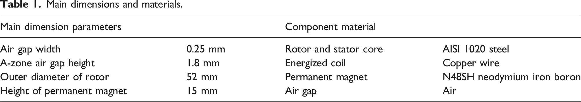
The coil consists of 70 turns, with excitation current amplitude ranging from 1 to 10 A and a frequency range of 10 to 200 Hz, increasing in increments of 10 Hz. The magnetic induction intensity within the electromagnetic actuator under various excitation current amplitudes and frequencies is depicted in Figure 16. As observed from the figure, when the current amplitude remains constant and the frequency increases, the magnetic field lines tend to concentrate on the inner surface of the stator iron core; when the frequency is constant and the amplitude increases, the intensity of the magnetic field lines notably increases, which is in line with the theoretical derivation. The magnetic induction intensity under different current amplitudes and frequencies.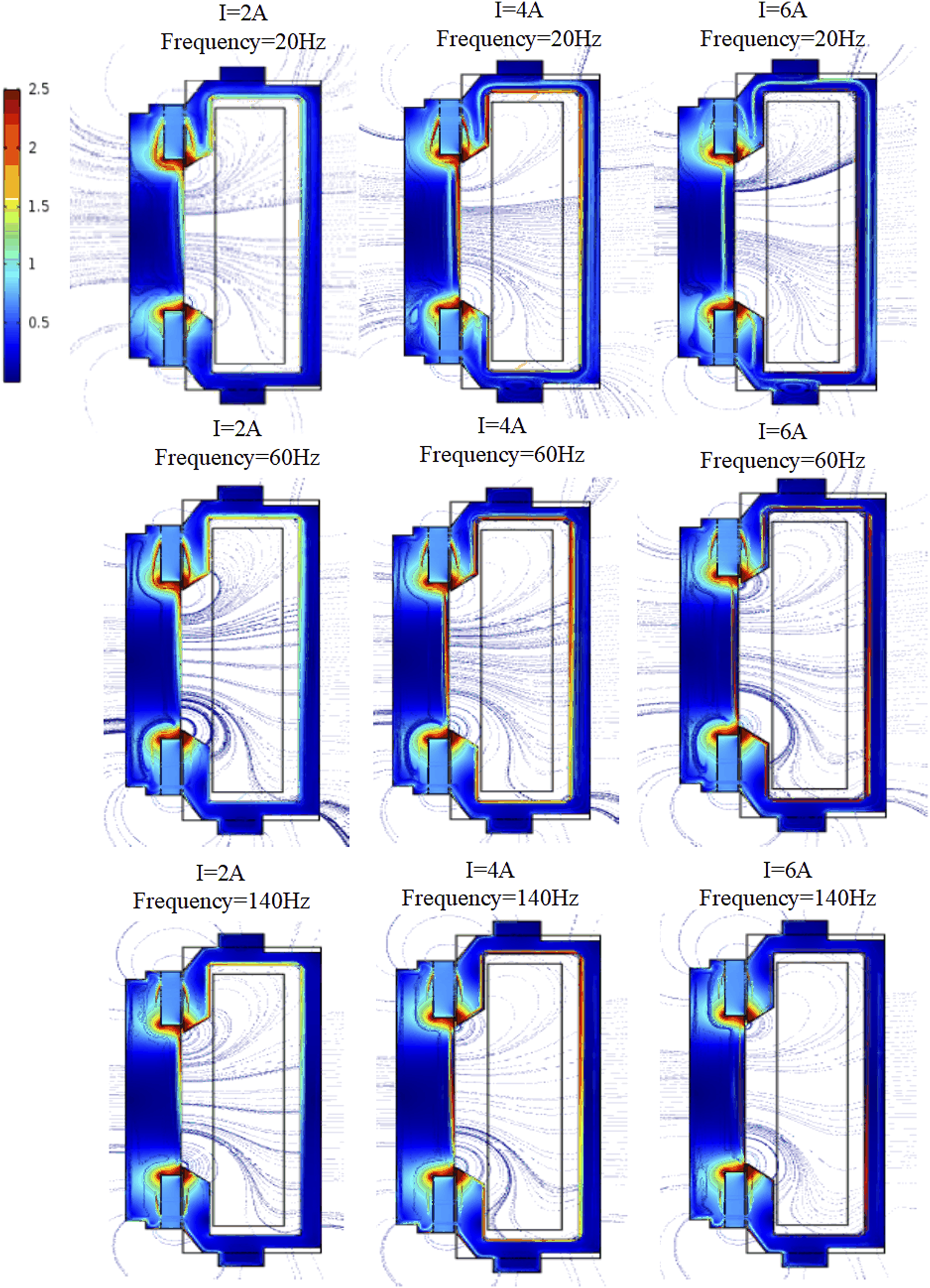
The electromagnetic force under different current amplitudes and frequencies is illustrated in Figure 17. The figure reveals that the electromagnetic force of the actuator is closely associated with the excitation current amplitude and frequency. It exhibits a linear positive correlation with the current amplitude, but gradually diminishes as the frequency increases. When the current is constant, the output force exhibits exponential decay as the frequency escalates. Electromagnetic force under different current amplitudes and frequencies.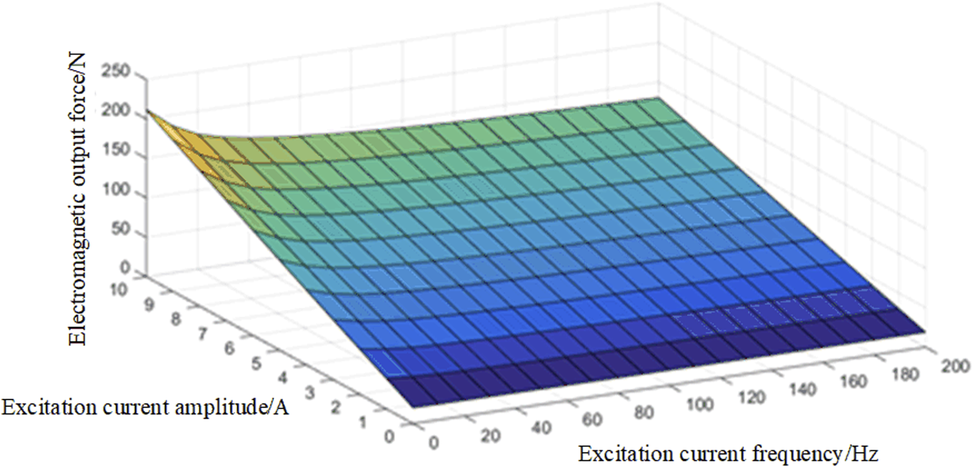
Design of passive hydraulic suspension unit
Physical model of hydraulic suspension unit
The hydraulic suspension system primarily comprises a rubber main spring, an upper fluid chamber, a lower fluid chamber, a decoupling membrane, and a rubber diaphragm. An inertial channel is formed between the upper and lower fluid chambers. To facilitate modeling and analysis, the following parameters are introduced: main spring stiffness Hydraulic section equivalent principal diagram. (a) Hydraulic suspension structure diagram. (b) Equivalent mechanical structure principal diagram.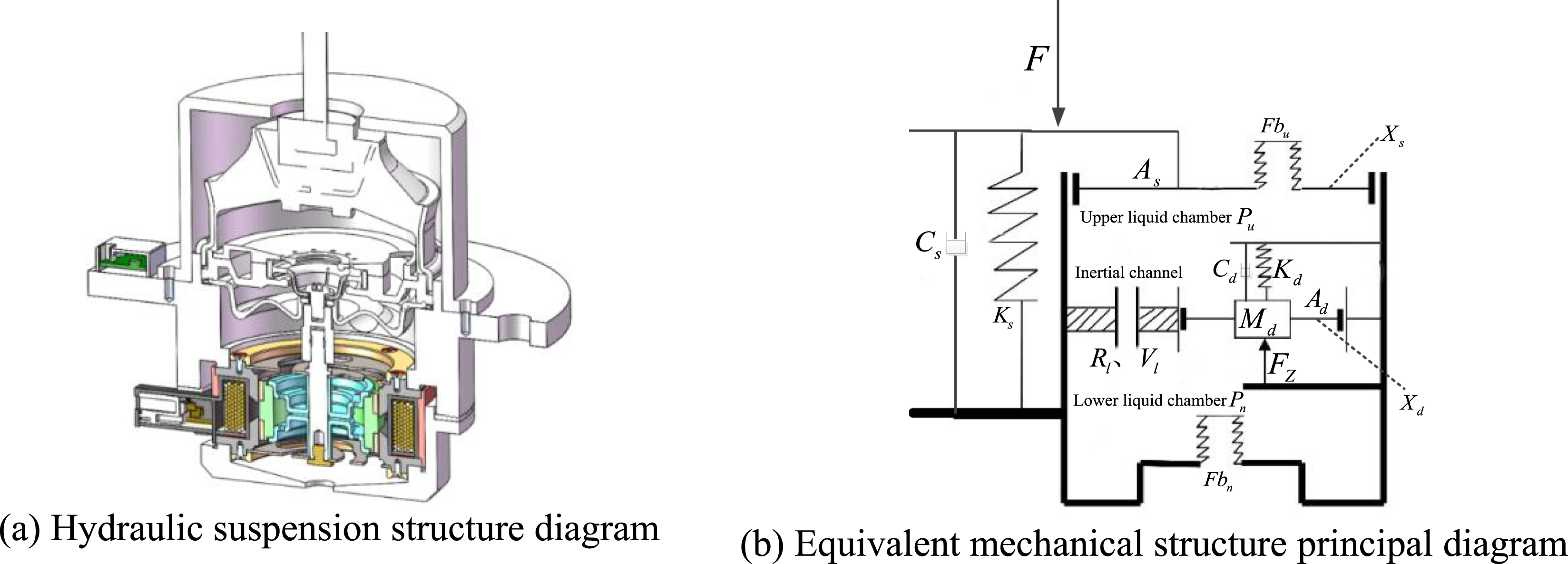
It is assumed that the oil volume is incompressible and flows exclusively between the upper and lower fluid chambers through the inertial channel. By applying the fluid continuity equation and conservation of momentum, the required relationships can be derived that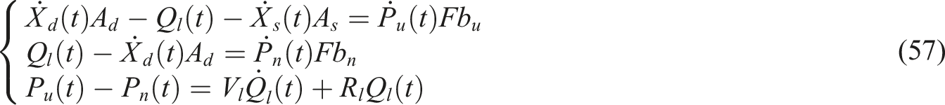
The rotor of the electromagnetic actuator is rigidly affixed to the decoupling membrane and secured to the outer shell through a spring plate and the outer edge of the decoupling membrane.
17
By performing a force analysis on the integrated rotor-decoupling membrane assembly as a single unit, the results can be derived that
The force transmitted to the base can be expressed as
Equations (57)–(59) describe the mechanical properties of the hydraulic suspension system. Since the equivalent viscous damping of the rubber main spring exerts a negligible impact on the isolator within the low-frequency range, it can be disregarded when computing the low-frequency dynamic characteristics. To facilitate analysis, the hydraulic suspension system is simplified into a dual-input single-output system, with 
Theoretically,
Transfer function of the hydraulic suspension
To determine the dynamic stiffness and electromagnetic force amplification coefficient, Laplace transformations are applied to equations (57)–(59), resulting in a matrix equation that can be expressed as follows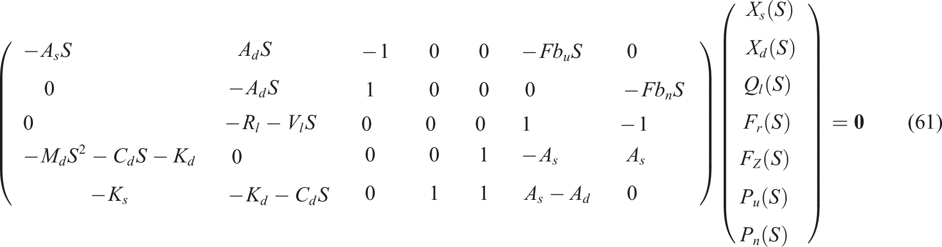
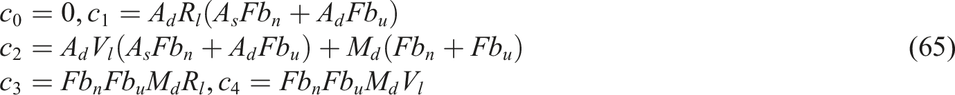
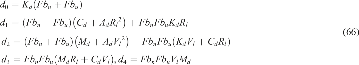
Simplify and solve to obtain
In the equation, the coefficients are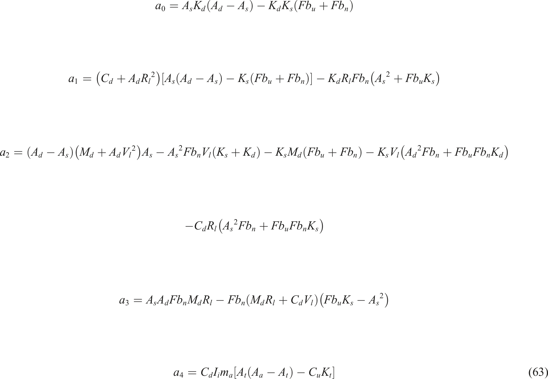

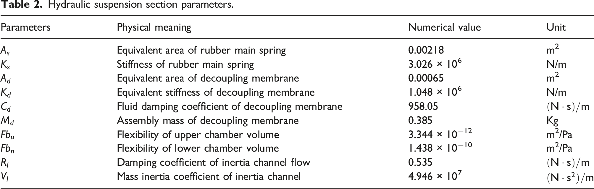
Hydraulic suspension section parameters.
Finite element simulation of hydraulic suspension
The geometry structure of the inertial channel is integrated into the COMSOL multi-physics simulation software. Utilizing the software’s computational fluid dynamics module, the laminar module is employed to calculate the R
l
-value of the inertial channel. The network division of the inertial channel geometry is depicted in Figure 19, while the flow lines of the velocity field within the inertial channel can be visualized in Figure 20. Schematic diagram of the geometric shape and mesh division of the inertial channel. Streamline diagram of the velocity field used for calculating the inertial channel 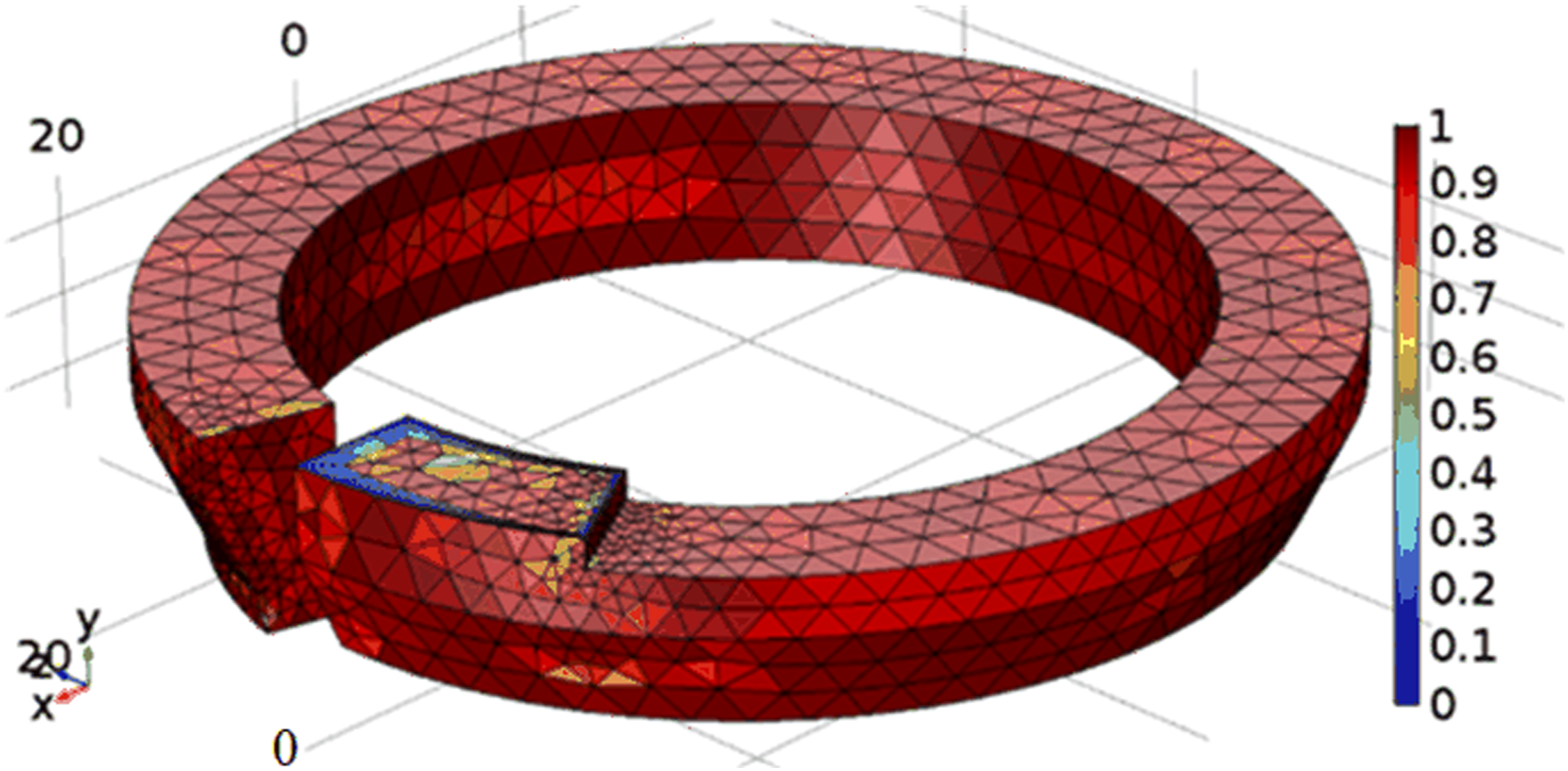
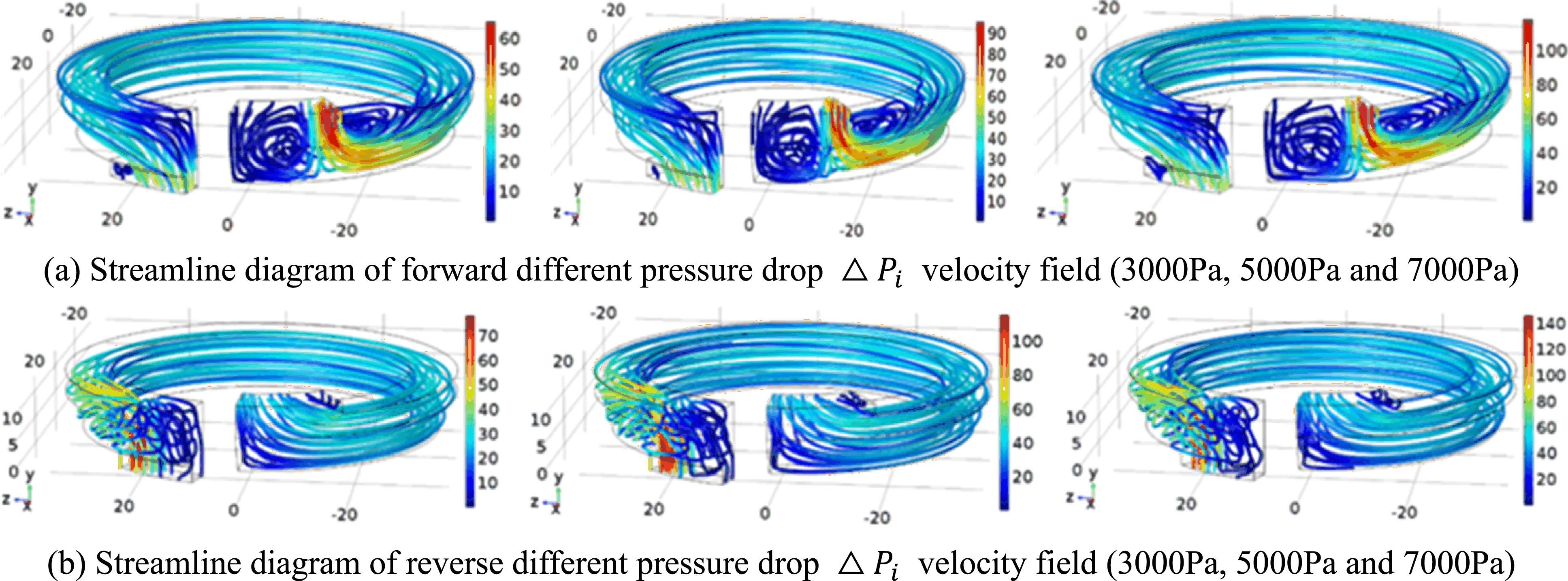
Calculate the (1) The asymmetry of the inertial channel relative to the horizontal plane and the disparities in geometric parameters between the inlet and outlet result in a differing flow field for oil flowing in both forward and reverse directions. As a consequence, the curve is not symmetrical with respect to the origin. (2) When a positive value of The curve of
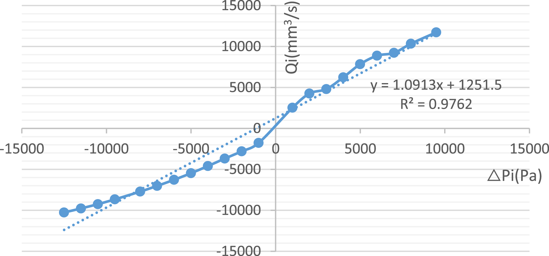
Similarly, the
The rubber main spring is designed with a sandwich structure consisting of a metal frame-rubber-metal frame. The upper frame is an aluminum alloy main spring core with a flange protrusion, which enables effective load transmission downward to the housing. Additionally, the aluminum core of the main spring is equipped with liquid injection and mounting holes in the middle, which serve the purposes of central injection and installation, respectively. The inverted trapezoidal shape of the rubber part of the main spring facilitates the effective upward transmission of hydraulic pressure in the upper liquid chamber without causing any radial deformation. Moreover, it imparts greater radial stiffness and lower axial stiffness to the main spring. The lower frame, which is an aluminum alloy main spring ring, plays a crucial role in the transmission of main spring load to the isolator housing, uniform load distribution, and installation and sealing effects.
The rubber main spring achieves a serialized load-bearing capacity by employing different grades within the same structure, utilizing 50#, 60#, and 70# rubber grades for stiffness simulation, thereby catering to the varying load demands of the rubber main spring. The main spring stiffness simulation employs a method that calculates the reaction force through fixed displacement: fixing the main spring’s aluminum ring and applying a downward fixed displacement to the upper end face of the main spring aluminum core for simulation. By obtaining the reaction force at this face and plotting the force-displacement curve, the main spring stiffness can be determined. Figure 22 displays the three-dimensional stress cloud diagrams of the three types of rubber main springs. Three-dimensional stress cloud map of type 3 rubber main spring. (a) 50#. (b) 60#. (c) 70#.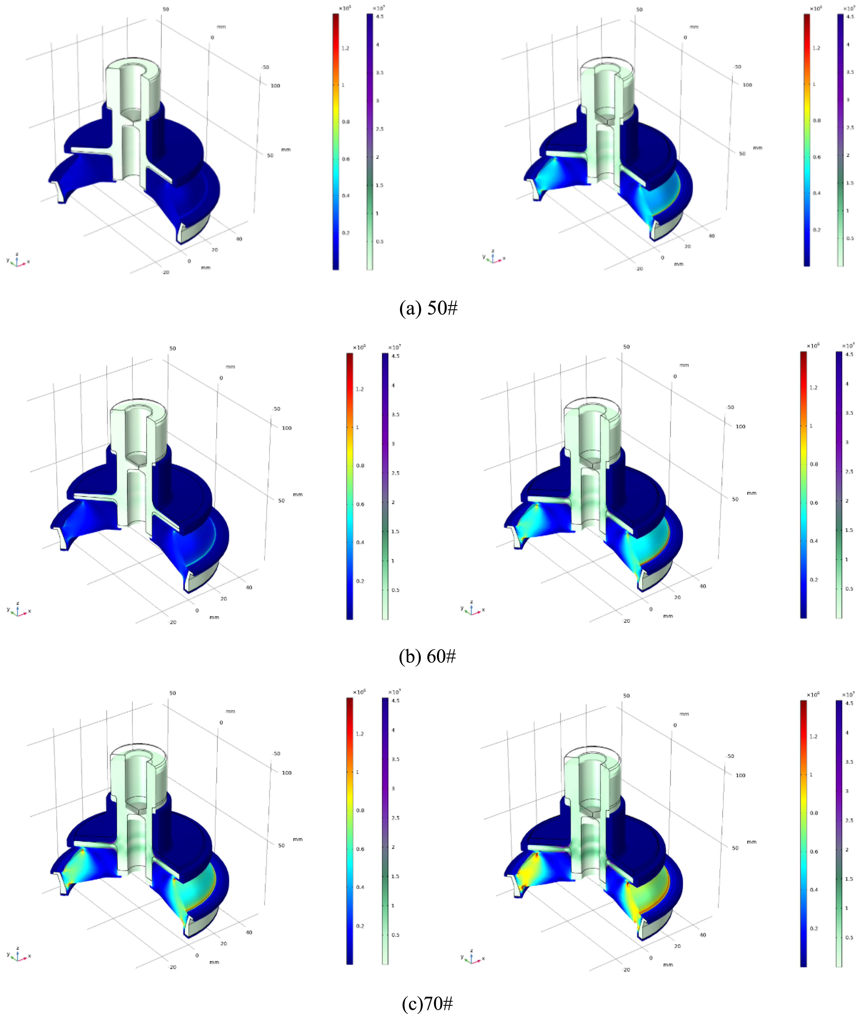
Upon post-processing the results, the reaction forces received by the aluminum core’s upper surface are calculated separately. The static force-displacement curves of the 50#, 60#, and 70# rubber main springs are then plotted, as illustrated in Figure 23. The figure reveals that different rubber stiffnesses yield varying static forces, with displacement and static force exhibiting a linear relationship. Additionally, the static force increases as stiffness escalates. Force-displacement curves of three types of rubber main springs (Blue-50#, Red-60#, Cyan-70#).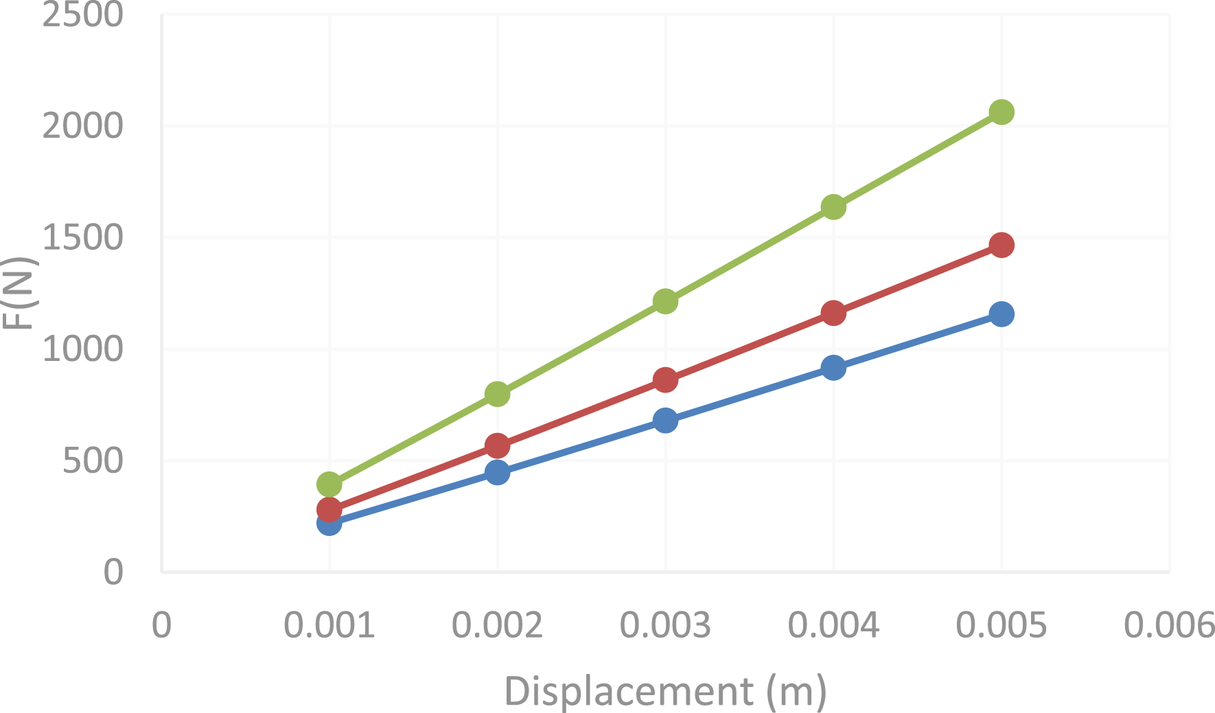
Performance test of hybrid isolator
Based on the theoretical and simulation analysis results, the components of the active-passive hybrid isolator are designed and processed, followed by assembly. The experiment consists of two steps: (1) measuring the electromagnetic force of the electromagnetic actuator itself (excluding the hydraulic suspension system); (2) measuring the force transmission rate and electromagnetic force magnification factor of the hydraulic suspension portion.
Performance test of electromagnetic actuator
Electromagnetic force, being a non-contact force, is challenging to measure directly and typically employs indirect measurement methods. A fixture is designed to secure the actuator’s rotor, ensuring adequate stiffness. The pressure at the rotor connection can be approximated as the actuator’s electromagnetic force. The physical fixture and actuator fixation method are depicted in Figure 24. Physical diagram of electromagnetic actuator output force testing device. (a) Schematic diagram. (b) Physical diagram.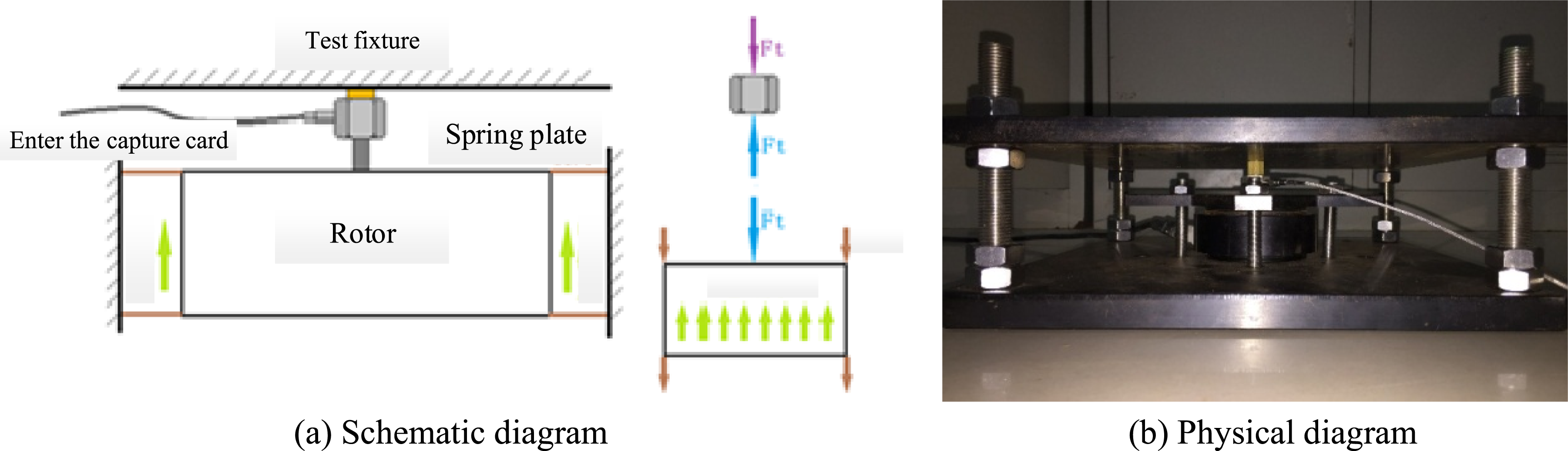
The test fixture comprises upper and lower plates. The electromagnetic actuator is positioned at the center of the lower plate and firmly secured by the flange. The upper plate is placed above the electromagnetic actuator, supported by external threaded columns at the four corners, and a charge-type force sensor is installed between the upper plate and the electromagnetic actuator. To prevent the weight of the upper plate from compressing the actuator’s rotor spring plate during fixture assembly, potentially leading to smaller measurement results or spring plate damage, nuts are installed on both the upper and lower sections of the upper plate. The lower nut supports the weight of the upper plate, preventing rotor compression, while the double nut installation safeguards against nut loosening due to vibration during the testing process.
The schematic diagram of the testing system is depicted in Figure 25. The primary hardware components include the PXI88404 core controller, PXI4498 sound and vibration acquisition board, PXI6229 voltage output board, and the PXIe1042Q chassis. Schematic diagram of experimental connection for electromagnetic force testing.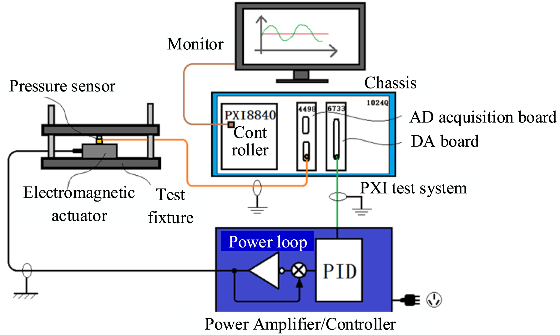
The excitation signal is generated by the controller, output through the DA board to the power amplifier, and drives the electromagnetic actuator. The excitation signal current amplitude ranges from 1 to 10 A with a step increment of 1 A; the sweep frequency range spans 20–200 Hz with a step increment of 10 Hz. The testing program is developed using LabVIEW software with a 10 kHz sampling rate and “N-sample” measurement mode. To minimize the influence of random errors on test results, the average of three measurements is taken as the test result for the electromagnetic force of the electromagnetic actuator, as illustrated in Figure 26. The figure demonstrates that at a constant frequency, the electromagnetic force increases approximately linearly with the increasing current; when the current amplitude remains constant, the electromagnetic force decreases with increasing frequency, and the attenuation rate gradually diminishes. Test results of electromagnetic actuator output performance.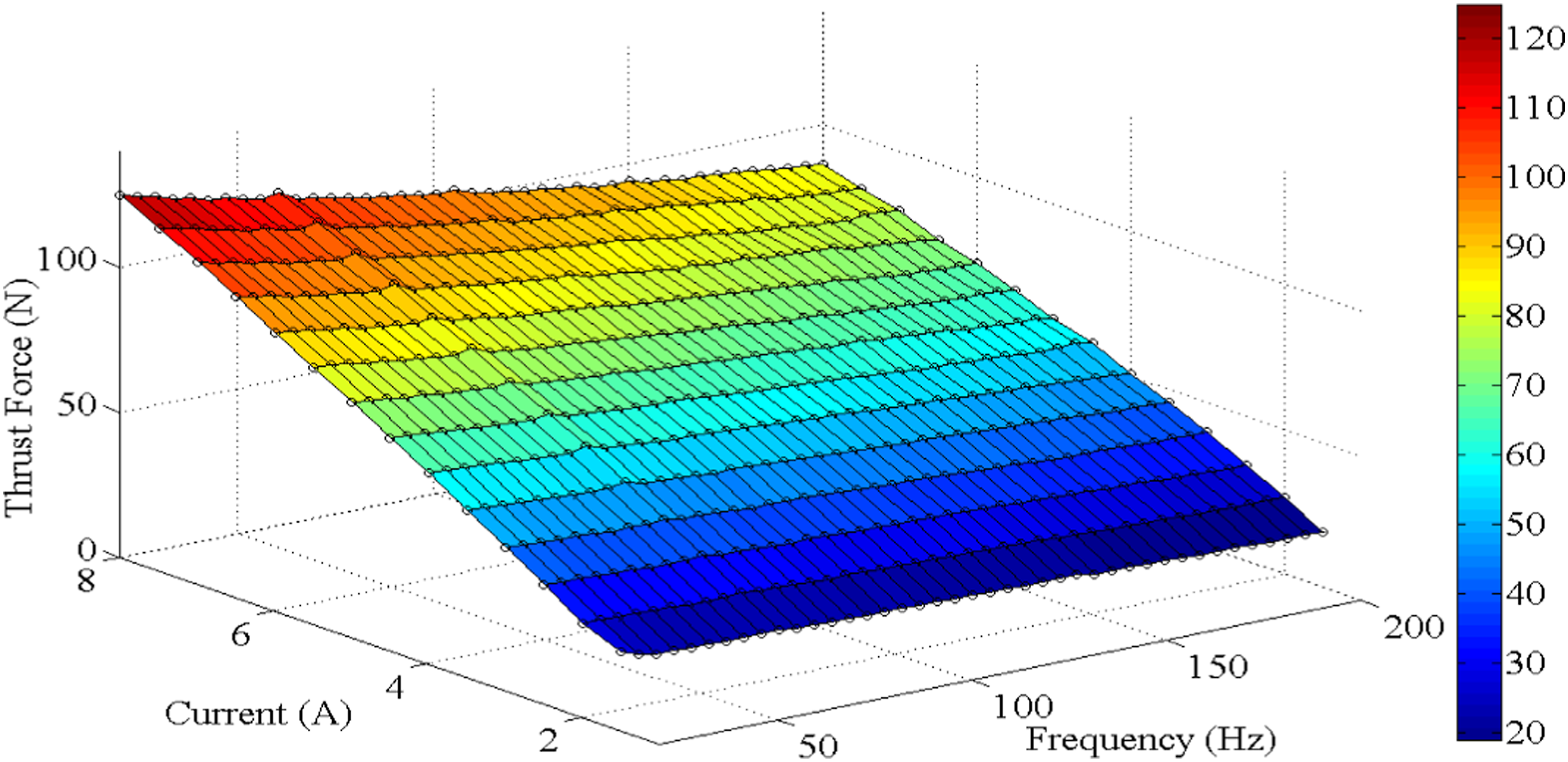
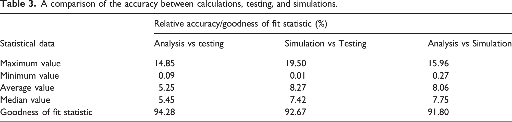
Test data and simulation data are compared and analyzed, with the comparison of the simulated electromagnetic force and the measured electromagnetic force data under specific current amplitudes and frequencies presented in Figure 27. The figure reveals the following insights: (1) When the excitation current amplitude is relatively small (I ≤ 1 A), the actuator vibration is not fully excited, resulting in the measured electromagnetic force being slightly smaller than the simulated electromagnetic force. (2) As the excitation current amplitude increases, the measured electromagnetic force becomes essentially consistent with or even surpasses the simulated value. Possible reasons for this discrepancy include inaccuracies in the simulation results due to errors in magnetic permeability, or the fixture’s insufficient stiffness, leading to pressure measurements at the rotor connection being slightly larger than the actual electromagnetic force exerted by the actuator. (3) When the excitation current amplitude is relatively large (I ≥ 8 A), the measured electromagnetic force is less than the simulated electromagnetic force, and the error increases with frequency. This discrepancy may arise from the actuator operating at high current and frequency for extended periods, causing it to heat up and alter the magnetic material properties, ultimately resulting in a decrease in the actuator’s electromagnetic force. Comparison of output performance results of electromagnetic actuators.
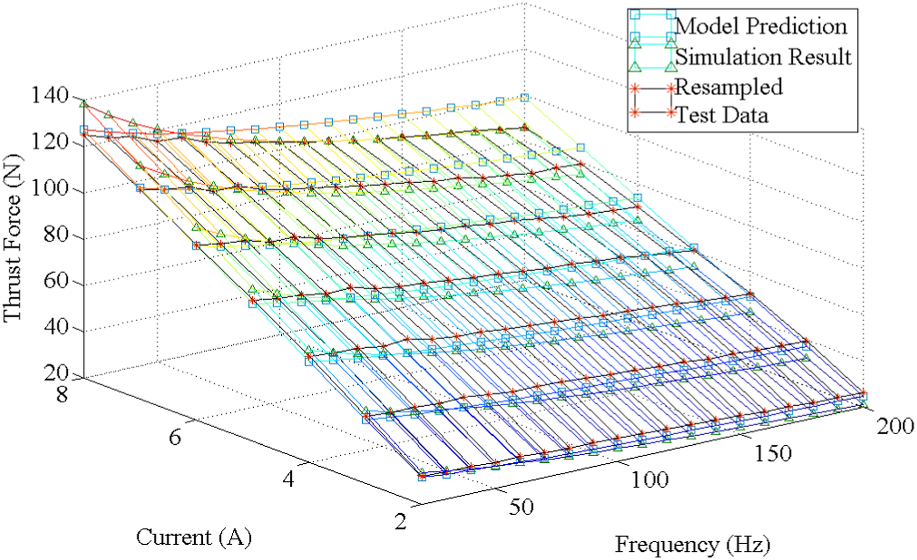
A comparison of the accuracy between calculations, testing, and simulations.
Performance testing of the hydraulic suspension section
The hydraulic device should not only amplify the electromagnetic force but also minimize vibration transmission to the base. Consequently, the force transmission ratio and dynamic force amplification factor are tested. The schematic and actual images of the test bench are illustrated in Figure 28. The test bench primarily comprises an exciter, an integrated active-passive isolator, acceleration sensors, force sensors, upper and lower plates, column guides, and more. The exciter is mounted on the upper plate, while the integrated active-passive isolator is installed between the upper and lower plates and connected to them using bolts. Three force sensors are placed between the hybrid isolator and the lower plate, and column guides are situated at the four corners of the lower plate. The upper plate slides on ball bearings, employing the same test system as described in Section 5.1. Test bench for hydraulic suspension part. (a) Schematic diagram. (b) Physical diagram.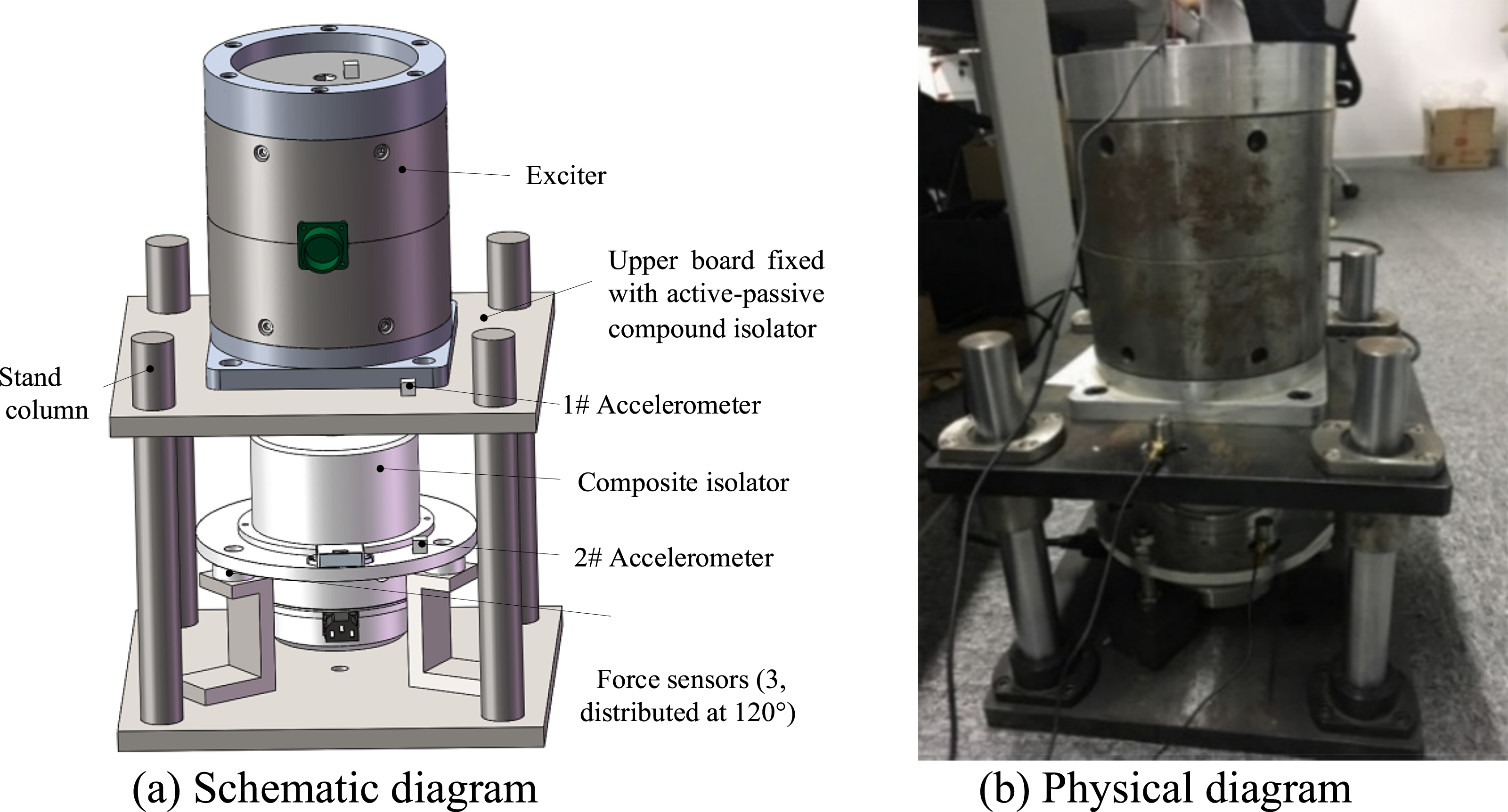
A steady sinusoidal signal is sent through the PXI-6733 board to the power amplifier, which drives the upper exciter to produce vibrations that generate excitation forces 
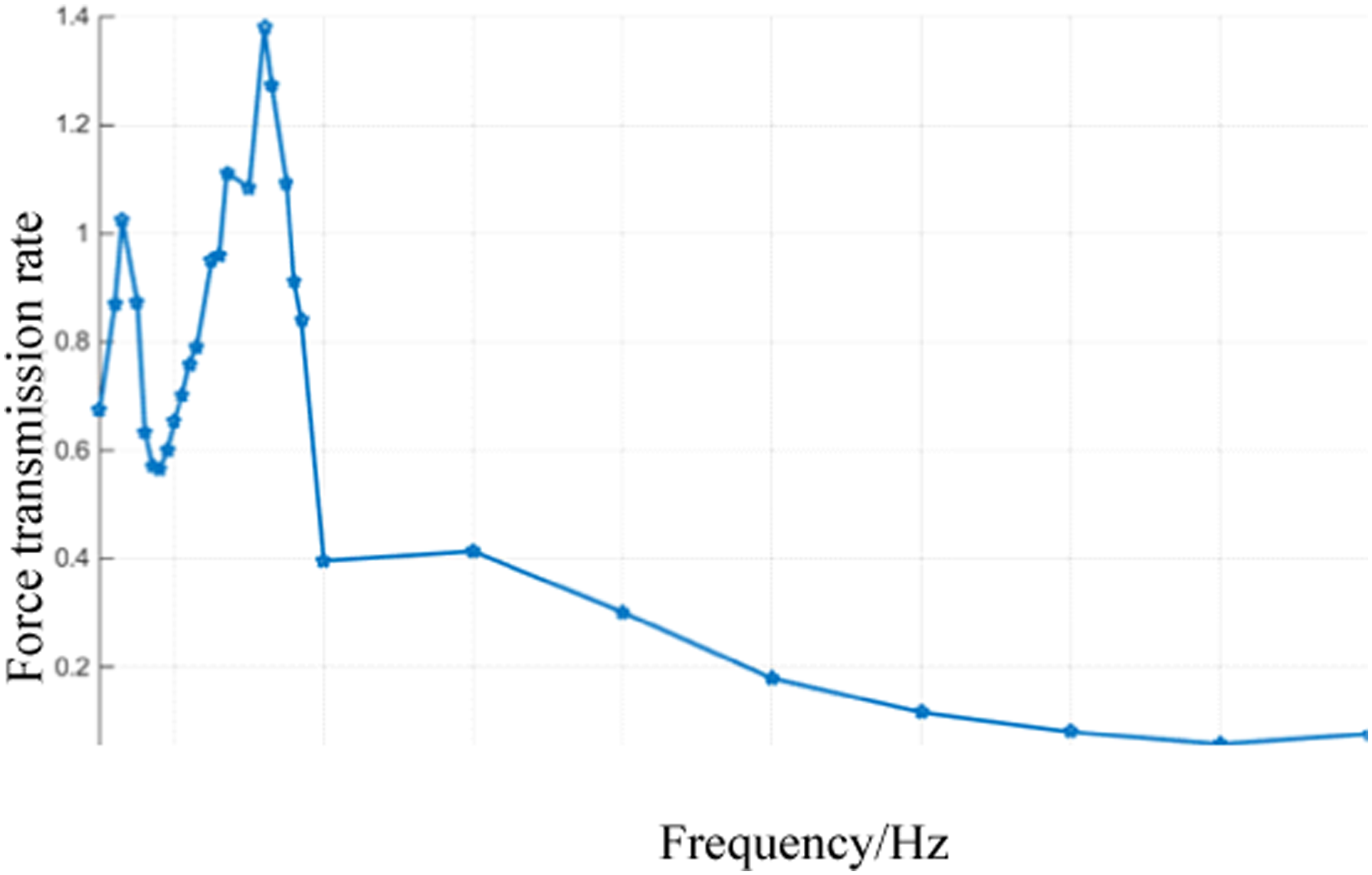
The force transmission rate curve is shown in Figure 29, and it can be seen from the figure that: (1) At low-frequency excitation, the force transmission ratio is relatively large, (2) Under high-frequency excitation, the force transmission rate is relatively small, Curve of force transmission rate for integrated vibration isolator.
A sinusoidal signal is transmitted through the PXI-6733 board to the power amplifier, which in turn drives the hybrid isolator to generate electromagnetic force (with the exciter remaining unstimulated). The force transferred to the lower plate is measured by three force sensors, and the sum of their values is used to determine the output force of the integrated isolator after “amplification” via the hydraulic device. The sampling rate is set at 10 kHz, and the measurement mode is “N sampling.” To minimize random errors in the experiment, the average of three measurements is employed as the final result. Since the relationship between the actuator’s electromagnetic force and current amplitude is not strictly linear, the current amplitudes are set at 3 A, 5 A, and 8 A, with frequencies ranging from 20 to 200 Hz in increments of 10 Hz for the experiment. By comparing the output force of the integrated isolator with the electromagnetic force of the actuator under the same excitation, the dynamic force amplification factor as a function of frequency can be analyzed at different current amplitudes. The fitted curve illustrating the variations in the dynamic force amplification factor with frequency is depicted in Figure 30. Dynamic force amplification coefficient under different currents.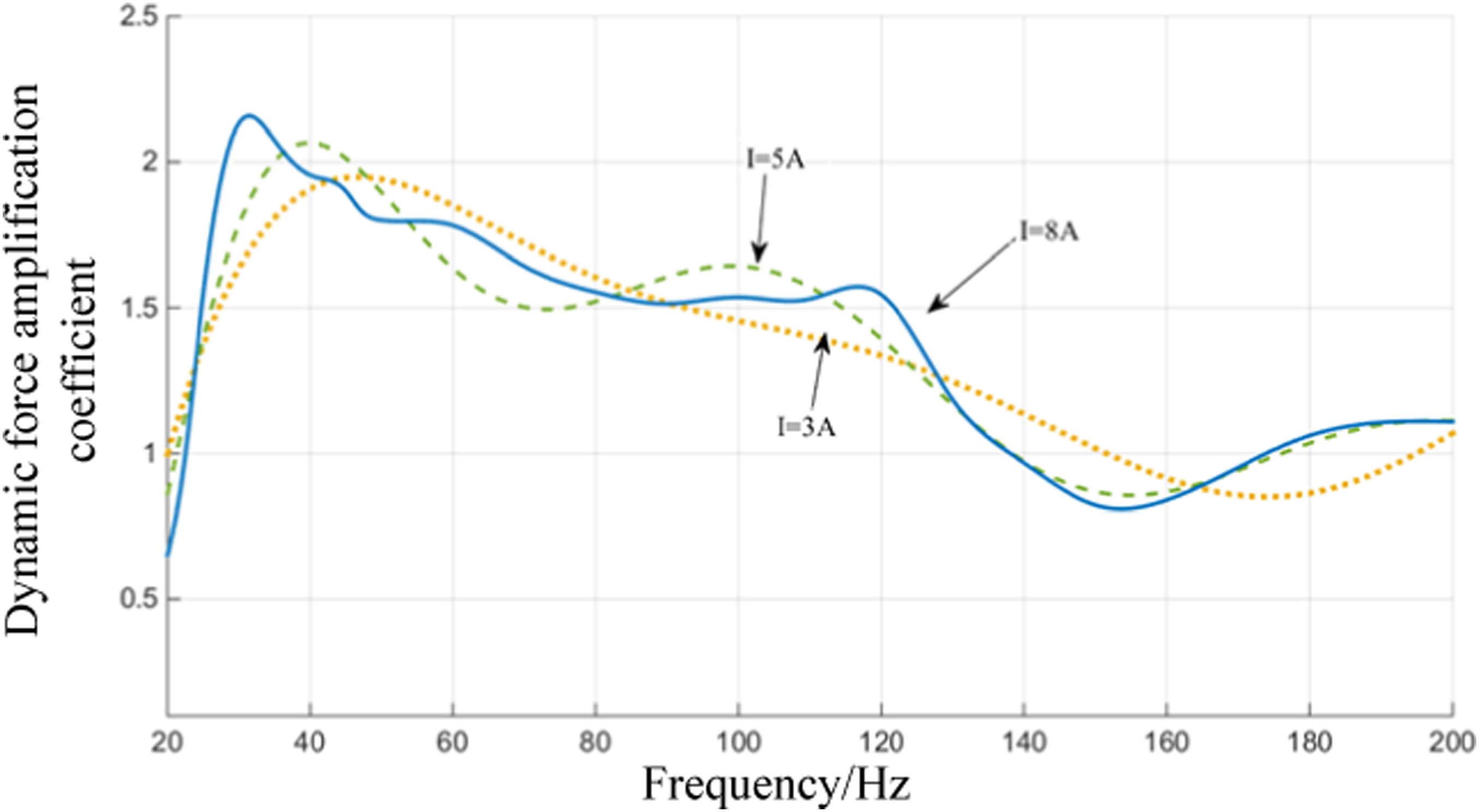
From Figure 30, it can be seen that: (1) The hydraulic suspension part significantly amplifies the electromagnetic force. In the 25–120 Hz frequency range, the amplification factor can reach 1.5. For frequencies above 140 Hz, the amplification effect is not obvious, meeting the design requirements and theoretical expectations. (2) Although the trends of the dynamic force amplification curves are generally similar under different current amplitudes, there are still some differences. The relationship between the dynamic force amplification factor and the excitation current amplitude requires further investigation.
Conclusion
This paper presented a breakthrough in key technologies such as the design of electromagnetic actuators with small volumes but high output forces, hydraulic suspension structure design and parameter matching, and magnetic circuit optimization for high-output force density actuators. With the operating conditions and characteristics of ship machinery equipment in mind, a design study is conducted on an integrated collector-electromagnetic-hydraulic-rubber active vibration isolation device suitable for ship machinery equipment. The main conclusions were summarized as follows: (1) The working principle of the integrated vibration isolator was explained, and the influence of the structural parameters of the integrated vibration isolator on the active control force and vibration isolation performance was studied. A design scheme was proposed for the ship integrated vibration isolator, which used electromagnetic actuators as the active component and rubber-hydraulic devices as the passive component. (2) The mechanical form of the active and passive components was designed. Through theoretical analysis, Comsol simulation, and experimental correction and other technical means, the material and structural parameters of the integrated vibration isolator were determined. Results indicated that the established models and methods can achieve over 90% accuracy in predicting the performance of the electromagnetic actuator’s output force. (3) The electromagnetic force test of the actuator and the performance test of the rubber-hydraulic device were carried out. The results showed that the electromagnetic output force increases linearly with the current amplitude and decreases with the increase of frequency. The amplification effect of the rubber-hydraulic device on the electromagnetic force can reach 1.5 times in the frequency range of 25 Hz–120 Hz.
In the future, an efficient and reasonable adaptive active control algorithm will be developed for the electromagnetic-hydraulic-rubber integrated vibration isolator designed in this paper, tailored to the structural and multi-equipment vibration centralized control requirements of ship machinery equipment. Practical and feasible solutions will be proposed to address unresolved issues in active isolation, such as the time-varying characteristics of secondary channels, reference signal mismatch, multi-frequency line spectrum vibration, strong interference, and impact.
Footnotes
Declaration of conflicting interests
The author(s) declared no potential conflicts of interest with respect to the research, authorship, and/or publication of this article.
Funding
The author(s) disclosed receipt of the following financial support for the research, authorship, and/or publication of this article: This research was supported by National Natural Science Foundation of China (Grant Nos. 52201389 and 51679245); Natural Science Foundation of Hubei Province (Grant No. 2020CFB148).