
Abstract
Tool vibration is a key factor that affects surface finish, generates noise, and reduces the tool life during conventional boring because of the excessive overhanging length of the tool holder. The interaction between the dynamics of the machine tool and the boring process led to progressive vibration. The creation of appropriate mechanisms in reducing tool vibration will help manufacturing industries to become more productive. In this research, in order to control vibration in the overhanging boring bar, a passive vibration control method was employed. Constrained layer dampers consist of boring bar, substrate, and elastic materials and it is used to minimize tool vibration produced during boring operation. The investigation utilized computational analysis through the ANSYS Workbench platform, employing key parameters such as the overhanging length of the tool holder (100, 150, and 200 mm), substrate material (aluminum, brass, and copper), and elastic material (Nitrile rubber, Natural rubber, and polyurethane). A comprehensive series of 27-run boring experiments were conducted to assess the impact of the constrained layer damper on tool vibration and cutting properties. The results of the study revealed remarkable improvements in various performance metrics. The constrained layer damper demonstrated an impressive 98% reduction in tool vibration, signifying its efficacy in dampening vibrational forces during the boring operation. Furthermore, a substantial 83% decrease in surface roughness was observed, indicating enhanced machining precision and surface finish. The constrained layer damper also exhibited a noteworthy 97.5% reduction in tool wear, highlighting its ability to significantly prolong tool life under challenging machining conditions.
Introduction
Nowadays high quality product with good dimensional accuracy, higher production rate, less tool wear, cost savings, and increase in performance with reduced environmental factor are the challenges dealt by the modern manufacturing industries. According to the hypothesis made by Guillem Quintana et al. 1 during machining, a weak dynamic stiffness tends to cause self-excited vibration, which can be reduced by applying a damping effect. In boring tool, vibration is caused by the dynamic interaction between workpiece and tool. Tool vibration leads to wavering surface on workpiece which results toward modulated chip thickness and increase in cutting force. Sam Paul et al. 2 reviewed the influence of tool vibration in metal cutting and concluded that tool vibration can produce significant levels of noise, affect surface quality of the product, and generate excessive tool wear. Authors reduced the tool vibration in metal cutting by adding a damper to the tool holder. Various types of dampers have been employed in the past to reduce tool vibration during metal cutting, which includes passive, active, and semi-active. The passive damper offers adequate dampening performance, affordable in comparison to other dampers, is straightforward in construction. 3
Regenerative chatter in the boring process can be controlled utilizing passive vibration control techniques including the installation of vibration absorbers using restricted layer dampers. A passive control technique consist of two elastic materials that typically have very low damping material is known as constrained layer viscoelastic layer.4,5 Regenerative chatter in machining operations was managed using tuned mass dampers, which were constructed from restricted viscoelastic dampers.6,7 A revolving boring bar made of carbon fiber epoxy composite was created, and experimental tests were utilized to determine the boring bar’s ideal geometry. 8 To increase chatter stability, a nano composite materials is inserted in boring bar. 9 A constrained layer damper was created to reduce chatter in end mill cutter during the end milling process. 10 To increase the machining stability of the boring process, a constrained layer damper was added to the boring bar. Constrained layer damper optimization was carried out through beam theory and computational analysis. 11 Johnson et al. 12 used computational analysis to determine the damping ratio on three-layer composite bar made of viscoelastic layers. In milling process, thin walled member was subjected to constrained layer damper and the results of the experiments revealed an improvement in surface finish. 13 Researchers looked at the effect of constrained layer damper in chatter frequency during drilling. 14 Yuhuanet al. 15 used constrained layer damper in boring bar to reduce regenerative chatter by computational method. The stability of chatter during deep hole boring was examined. Constrained layer dampers was utilized to increase a thin boring bar’s resistance to chatter. 16
Recent studies have made significant strides in optimizing cutting parameters for specific materials, with a notable example being the investigation into finishing milling of Hardox 400 steel by F Kura. 17 Their study employed PVD TiAlN+TiN coated carbide inserts, and the experimental design followed a Taguchi L16 orthogonal array. The evaluation criteria were based on the signal/noise (S/N) ratio, providing a comprehensive assessment of the impact of control factors on surface roughness. In a notable contribution to the field, Nas, Engin, and Fuat Kara 18 conducted machinability tests on a corrosion-resistant superalloy, subjecting it to both shallow and deep cryogenic treatments via EDM. This study underscores the significance of cryogenic treatment types on the processing performance of the material, introducing an experimental design encompassing pulse-on time, peak current, and material types. The research leverages the Taguchi L18 method to optimize parameters, offering a systematic approach to achieving optimal results for average surface roughness (Ra) and material removal rate (MRR). F Kura et al., 19 represents a notable contribution to the field, emphasizing the impact of different cutting parameters on the performance of CVD and PVD-coated carbide tools. Guvenc et al., 20 proposed a sliding mode-based active vibration control system which was deployed to mitigate chatter during turning processes. In sliding mode control, the acceleration data received from the cutting tool was used as feedback information and the same data was used for identifying the necessary reaction force for the actuator. Also mathematical model was created by taking the highest vibrations in the direction of the plunge axis. Vibrations signals generated during machining were collected, filtered, integrated, and analyzed using Fast Fourier Transform (FFT) technique. From the results they concluded that chatter was controlled with high accuracy and sliding mode controller technique offers a promising and holistic approach in the dynamic nature of the metal cutting process.
Constrained layer damper is a relatively new technology that has gained significant attention in recent years due to its effectiveness in reducing structural vibrations. Constrained layer damper is a damping technique that involves sandwiching a viscoelastic material between two stiff layers of metal or composite materials to form a composite panel and is widely used in the aerospace, automotive, and civil engineering industries. The novelty of constrained layer damper lies in its ability to effectively reduce structural vibrations over a broad range of frequencies. The viscoelastic layer in the composite panel dissipates the mechanical energy of the vibration thereby, effectively reducing the amplitude and the duration of the vibration. Unlike traditional damping techniques such as passive damping and tuned mass dampers, which are only effective at specific frequencies, constrained layer damper is effective over a broad range of frequencies, making it a versatile and highly efficient technique. Another advantage of constrained layer damper is its lightweight and compact design. The sandwiched composite panel can be made to fit any shape or size, making it suitable for a wide range of applications. Moreover, since the constrained layer damper is a passive damping technique, it requires no external power source or maintenance, making it highly cost-effective in the long run. The constrained layer damper is a novel and highly effective damping technique that has gained significant attention in recent years due to its broad frequency range, lightweight and compact design, and cost-effectiveness. Its versatility and efficiency make it an ideal solution for reducing structural vibrations in a wide range of applications. In the recent decade, many researchers have studied the effect of constrained layer damper in engineering applications. However, a research gap was identified in the area of suppression of tool vibration during boring process using constrained layer damper technique. Constrained layer damper was designed and developed by substrate and elastic material in a ring type on boring bar. The study involved designing, developing, and testing of constrained layer damper with varying overhanging length, substrate material, and elastic material to examine the effects of tool wear, surface finish, and tool vibration during boring of hardened AISI4340 steel. The constrained layer damper demonstrated high effectiveness in reducing tool vibration, resulting in notable improvements in both tool life and surface finish during the boring of hardened AISI4340 steel.
In Sect. 2, we described the computational analysis of boring tool with constrained layer damper by varying overhanging length, substrate material, and elastic material. In Sect. 3, we introduced the 27 run experimental analysis by varying overhanging length, substrate material, and elastic material in boring tool. In Sect. 4, the results and discussion section we analyzed experimental analysis and computational analysis results. In Sect. 5, we described the conclusion and outcomes of the research purpose and the advantages of using constrained layer damper.
Computational analysis of boring tool with constrained layer damper—design of constrained layer damper
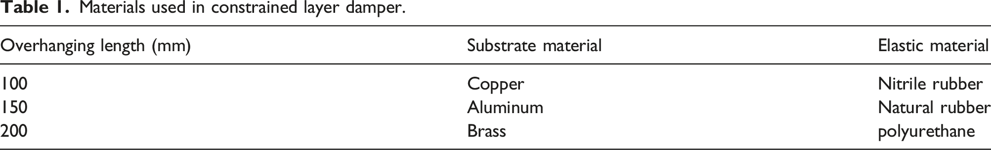
Materials used in constrained layer damper.
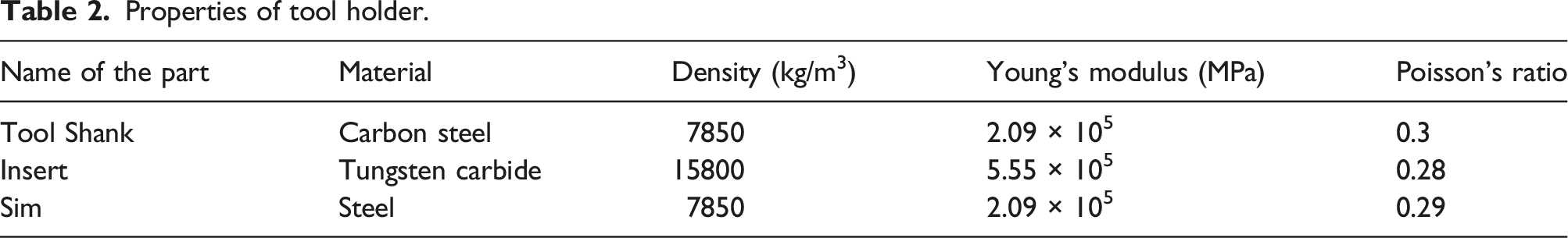
Properties of tool holder.
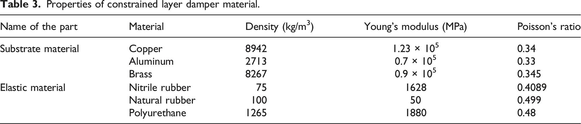
Properties of constrained layer damper material.
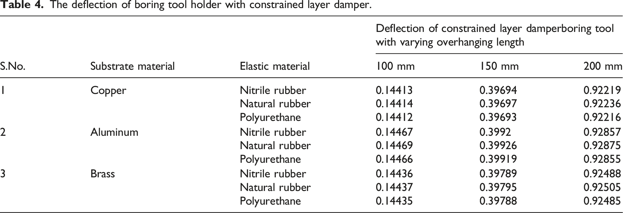
The deflection of boring tool holder with constrained layer damper.
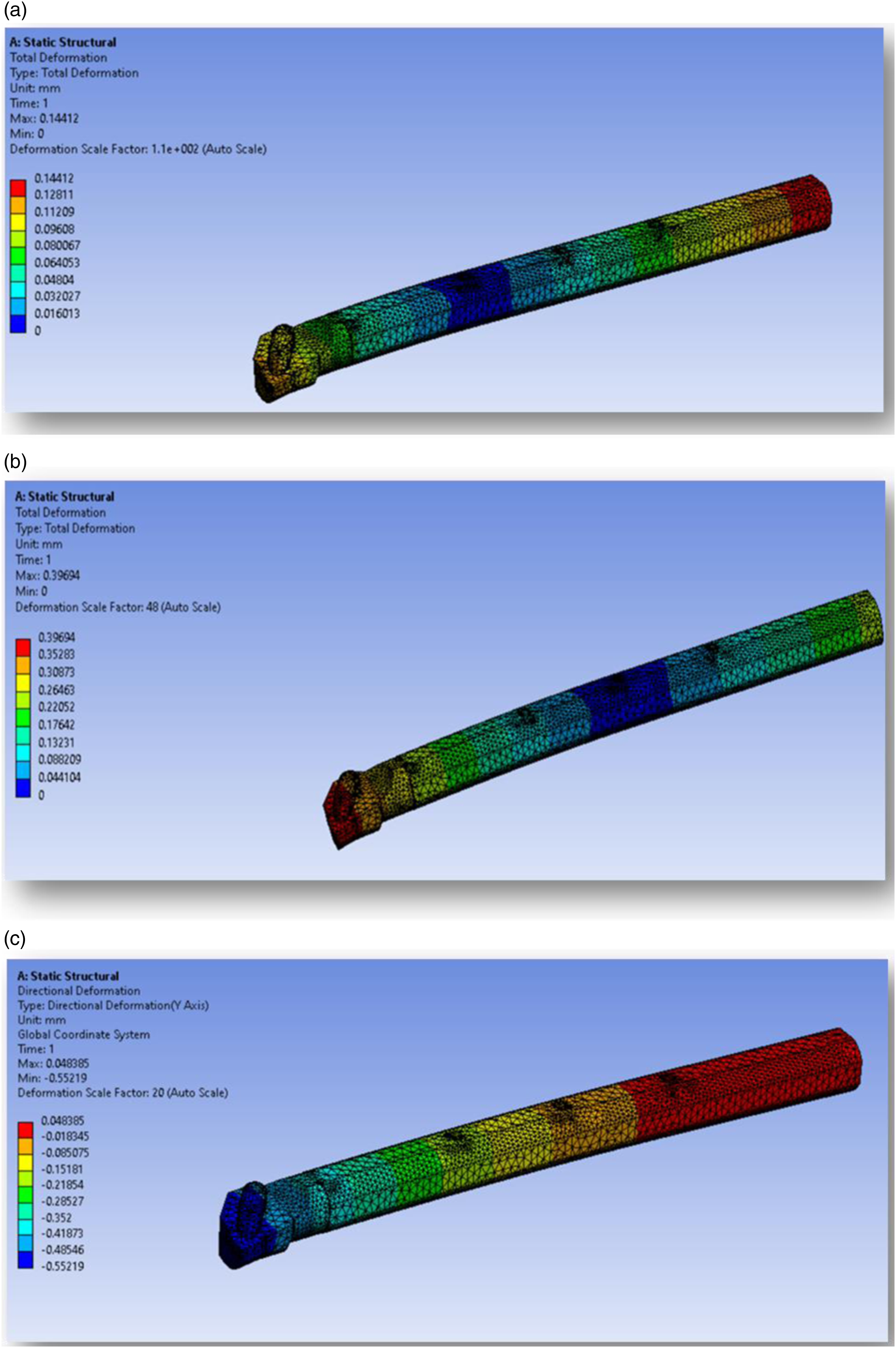
(a) Deflection for 100 mm overhanging length with constrained layer damper. (b) Deflection for 150 mm overhanging length with constrained layer damper. (c) Deflection for 200 mm overhanging length with constrained layer damper.
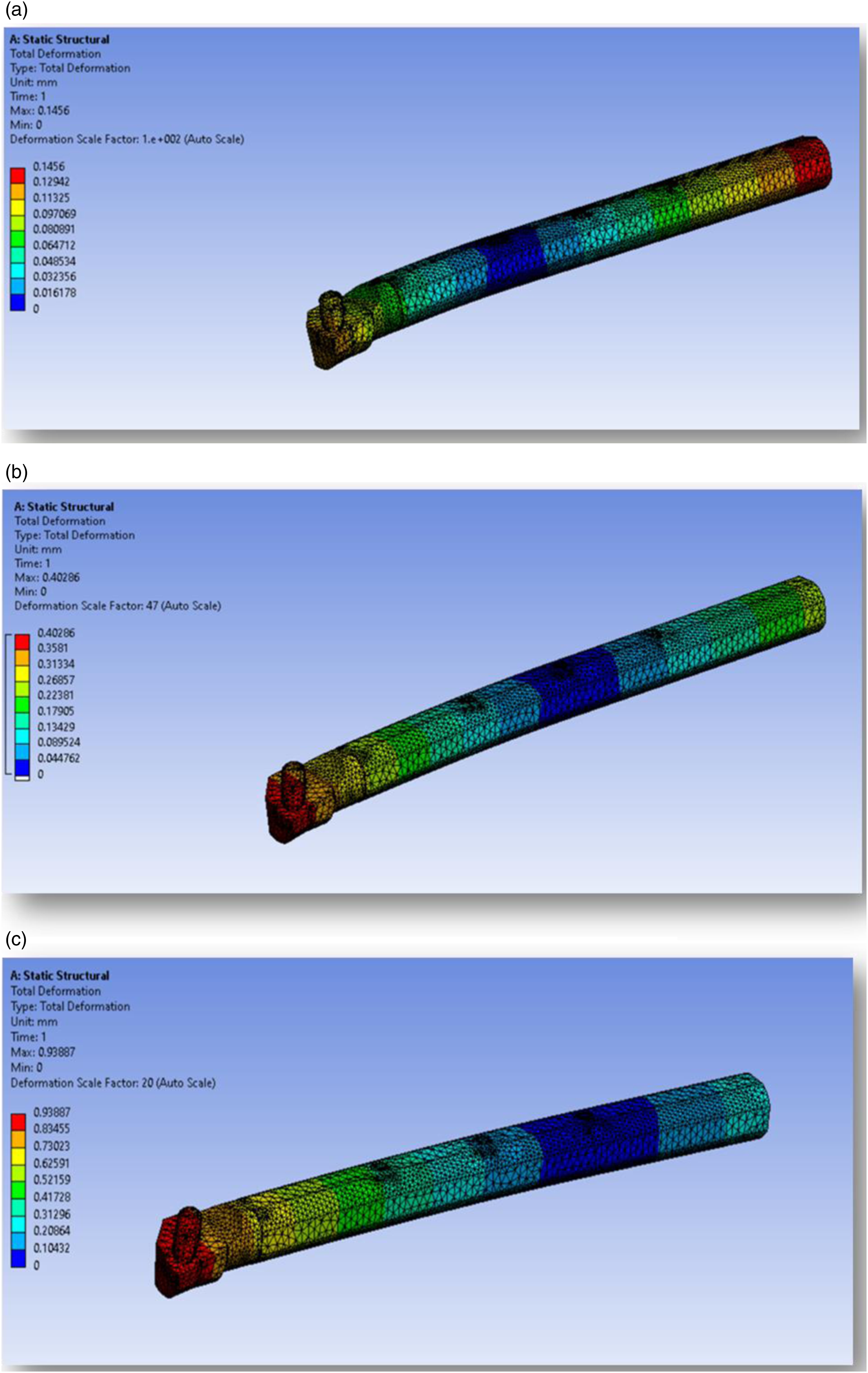
(a) Deflection for 100 mm overhanging length without constrained layer damper. (b) Deflection for 150 mm overhanging length without constrained layer damper. (c) Deflection for 200 mm overhanging length without constrained layer damper.
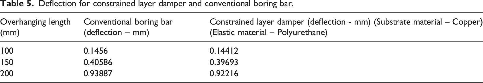
Deflection for constrained layer damper and conventional boring bar.
Constrained layer damper on tool vibration (100 mm overhanging length) during boring process.

Constrained layer damper on tool vibration (150 mm overhanging length) during boring process.
Constrained layer damper on tool vibration (200 mm overhanging length) during boring process.
Experimental analysis
Three hollow drilling bars with and without constrained layer damper were fabricated to study the effect of constrained layer damper on tool vibration and cutting performance during boring process. In one of the hollow boring bars, the constrained layer damper was press fitted, and machining tests were run. Additionally, it was made sure that all of the boring bars had the same specifications for comparison.
Material and parameters
A boring tool with the specifications S25T PCLNR 12F3 was employed in this study. It had 30 mm diameter and 300 mm length. Workpiece consist of 100 mm outer diameter, 50 mm diameter, 100 mm length, and is manufactured of AISI 4340 steel with a 45 HRC.
23
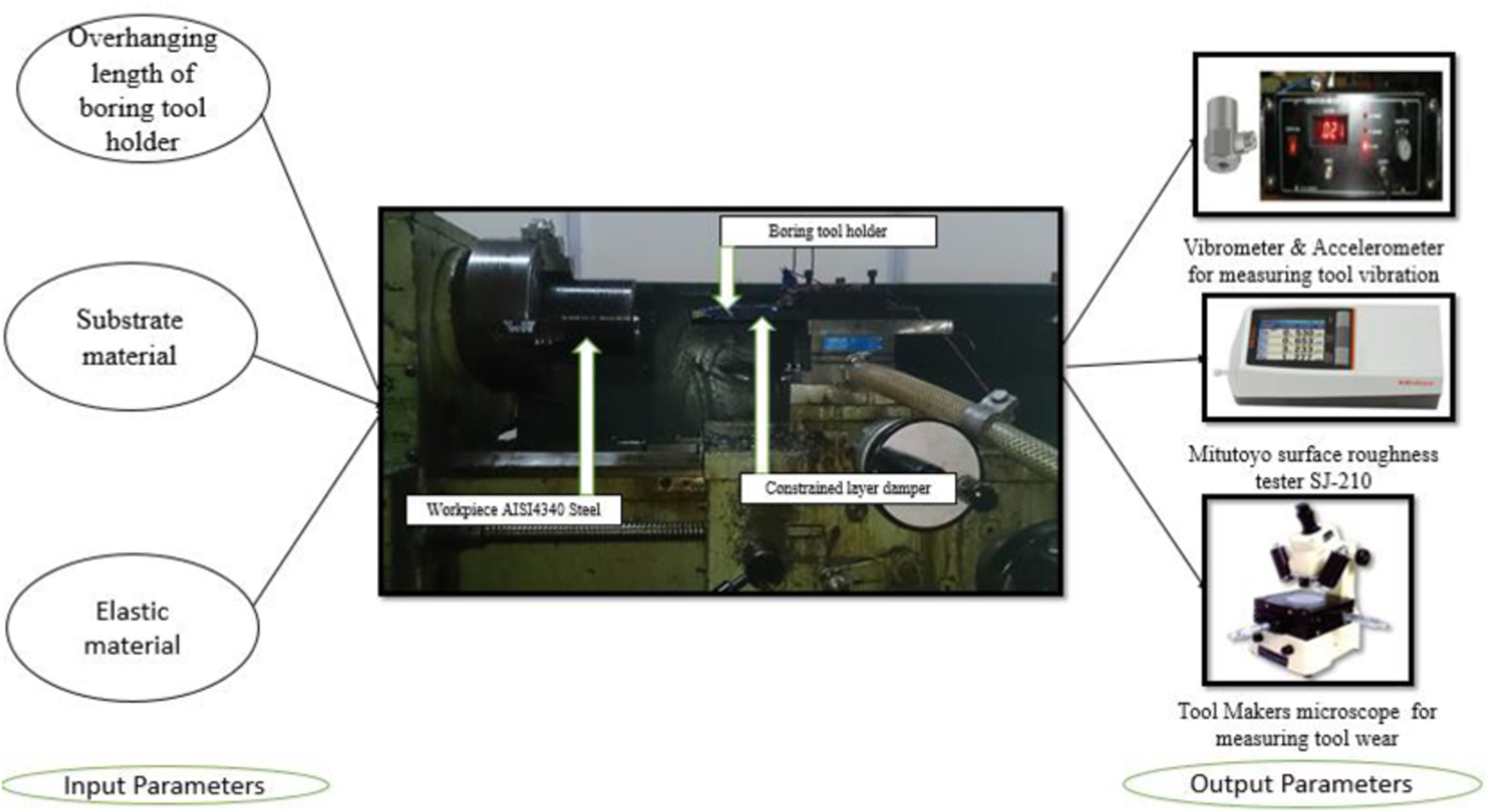
The construction of a boring bar using a constrained layer damper is shown in Figure 6, and the experimental constrained layer damper setup with input and output parameters is shown in Figure 7. A 200 mm long, 15 mm diameter carbon steel boring tool was drilled using spark machining. In the fabrication process, a hollow drilling bar made of substrate and elastic material was pressed inside which is locked with adjustable screw made of steel. 100 m/min for the cutting speed, 0.06 mm/min for the feed, and 0.5 mm for the depth of cut which optimized. Cutting tests were conducted for 2 min in a dry cutting environment.
24
Constrained layer damper in a boring bar. Experimental setup of constrained layer damper.
Design of experiments
To calculate the static deflection with modification in overhanging length, substrate material, and elastic material in computer analysis, design of tests is carried out. In experimental analysis, it is also utilized to quantify tool wear, tool vibration, and surface roughness by altering the overhanging length, substrate material, and elastic material. DOE is carried out using Minitab software, which primarily relies on a statistical foundation. There are a total of 27 experiments, with three levels and three factors.
Analysis of variance
Analysis of variance is utilized to determine input factors effect on machining of the boring process. Analysis of variance is used to determine the important cutting parameters that affect the material’s machinability.
25
The total sum of squared deviations, which is used to rank the cutting parameters, is estimated using the equation shown below.
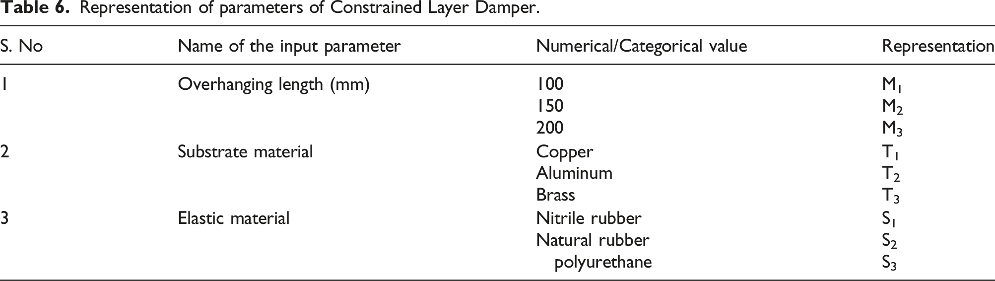
Representation of parameters of Constrained Layer Damper.
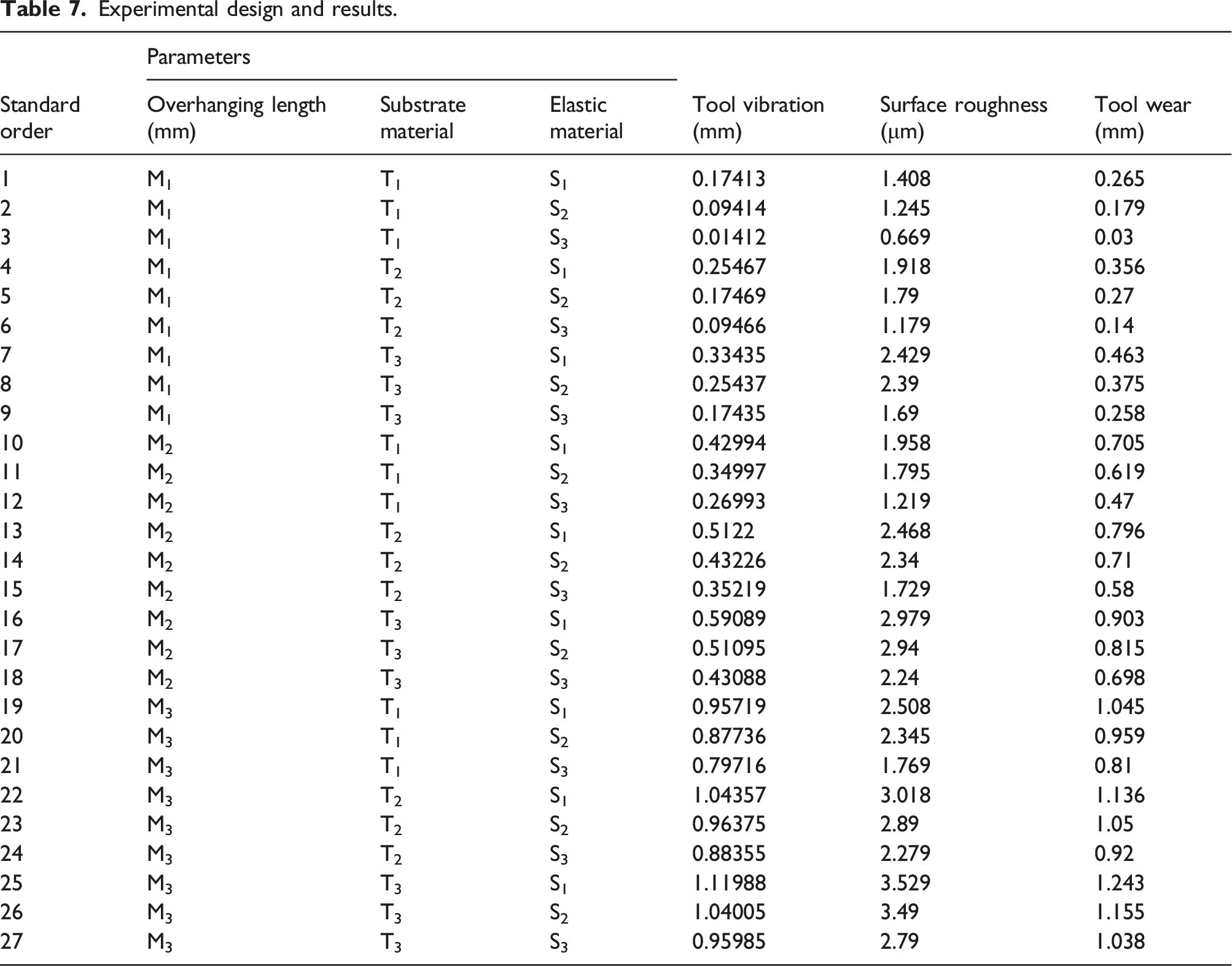
Experimental design and results.
In metal cutting, flank wear, nose wear, and crater wear were considered as influential wear indices in measuring the quality of the finished product. SEM images of flank wear, nose wear, and crater wear for a specimen is shown in Figure 8. Flank wear occurs on the relief face of cutting tool and it is due to the rubbing of cutting tool relief face against the workpiece. This flank wear is caused by abrasion mechanism and progress gradually resulting towards deflection of cutting tool which in turn affects the accuracy of the manufactured product. Nose wear occurs in the nose area of cutting tool which results in catastrophic tool failure. Due to the accuracy factor in measuring nose wear, measurement of nose wear was found to be difficult. Crater wear occurs in the rake face of cutting tool and accompanied by excessive cutting temperature. This rate of diffusion increases exponentially with the rise in temperature. Among these wears, flank wear which is an indication of progressive tool wear and also has an effect on tool vibration, was considered and measured in this study. SEM images of flank wear, nose wear, and crater wear.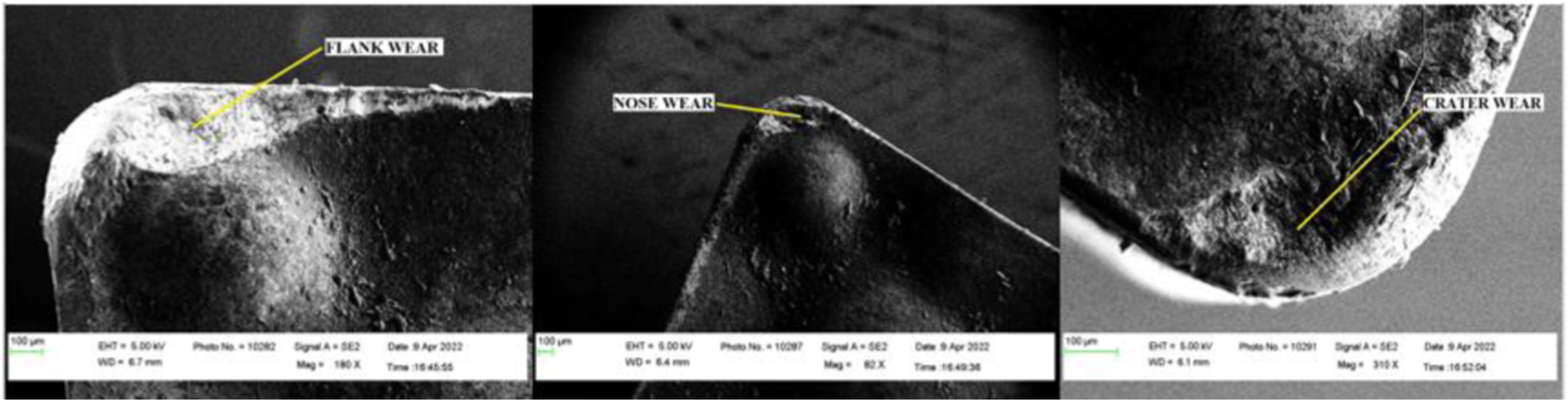
Result and discussion
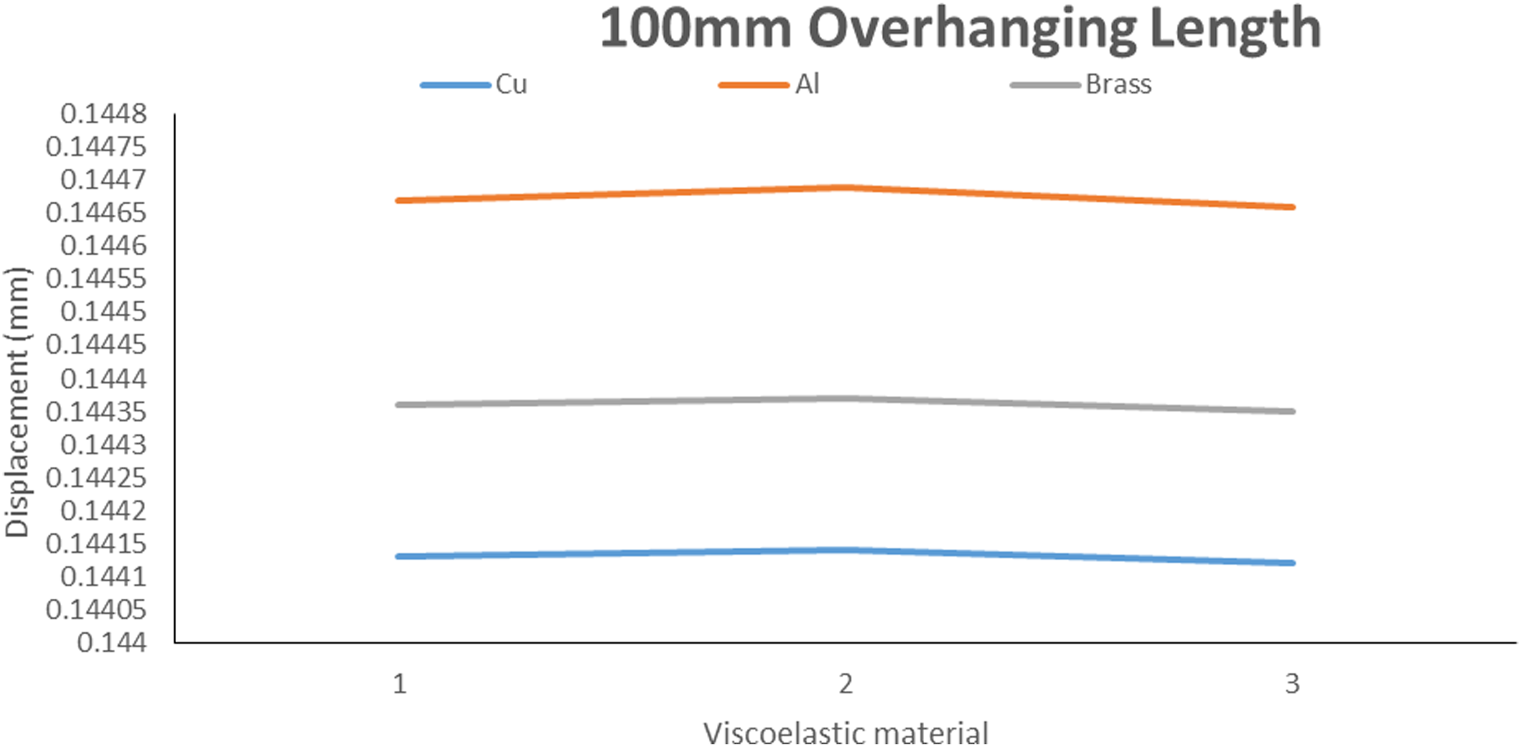
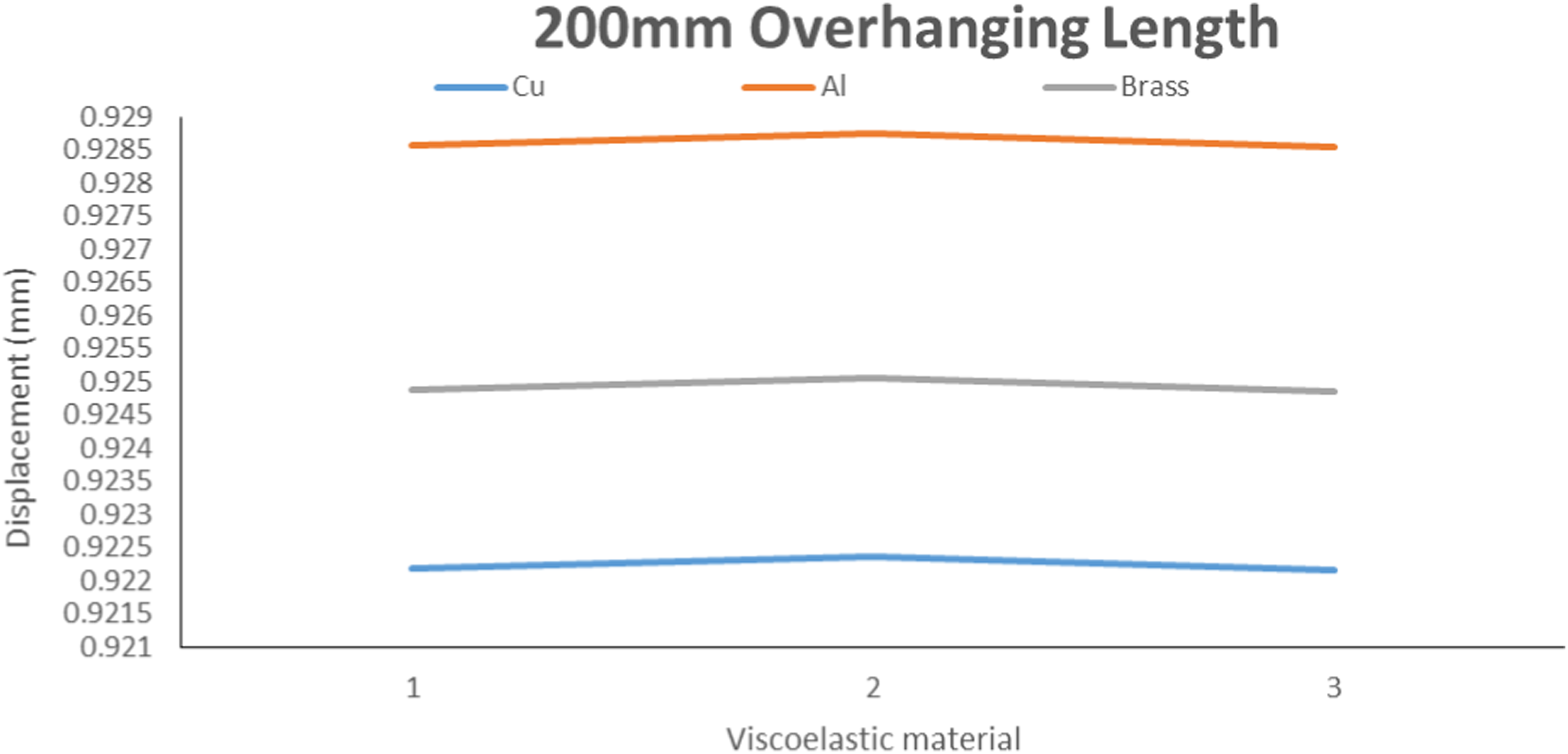
Static analysis was employed to calculate the deflection. The study focused on varying overhanging lengths (100 mm, 150 mm, and 200 mm) of boring tool holders. Both elastic and substrate materials were considered in the analysis. The study compared tool holders with constrained layer dampers and conventional boring bars. Separate static studies were conducted for each of the three overhanging lengths. Table 4 provides details on the deflections of constrained layer dampers constructed from various materials. Table 4 presents the maximum deflections for tool holders with and without constrained layer dampers. Figures 1(a)–(c) and 2(a)–(c) illustrate deflection plots for tool holders made of substrate and elastic materials at different overhanging lengths. The maximum deflection was measured at different overhanging lengths, with and without constrained layer dampers. For instance, at 100 mm overhanging length, the deflection was measured as 0.1442 mm for tool holders with constrained layer dampers and 0.1456 mm for tools without dampers. The comparison between boring bars with and without constrained layer dampers. The deflection was measured for a 200 mm overhanging length, showing a reduction in deflection when constrained layer dampers were used. Constrained layer dampers made of copper (substrate material) and polyurethane (elastic material) were identified as providing better results compared to other materials. Table 5 and Figures 3–5 depict the comparative results shows that deflection increases as the clamping length decreases.
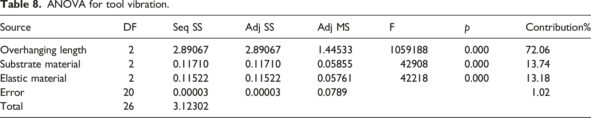
ANOVA for tool vibration.
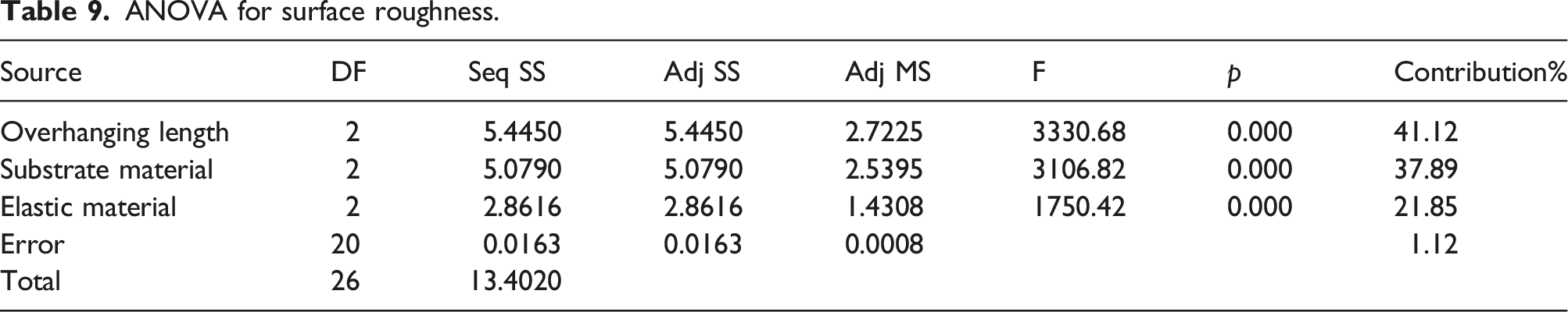
ANOVA for surface roughness.
ANOVA for tool wear.
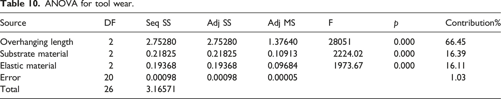
Overhanging length has the highest percentage effect on tool vibration because longer overhanging lengths lead to increased deflection and higher leverage, amplifying vibrations. Shorter overhanging enhances stiffness and reduces vibration. Overhanging length contributes the most to surface roughness because shorter overhanging lengths result in less tool deflection, leading to finer surface finishes. The effect is more pronounced compared to substrate material and elastic material. Overhanging length has the highest percentage contribution to tool wear because longer overhanging lengths increase the likelihood of tool vibration and wear. Shorter lengths minimize these effects, emphasizing their impact on tool wear.
From Figure 9(a), tool vibration is reduced (less than 0.2 mm) at the contact of level 1 of overhanging length (100 mm) and substrate material (copper). But tool vibration is high (more than 1 mm) at level 3 region of overhanging length (200 mm) and substrate material (brass). Similarly in Figure 9(b), tool vibration is reduced (less than 0.2 mm) at the contact of level 3 of overhanging length (100 mm) and elastic material (Polyurethane). But tool vibration is high (more than 1 mm) at level 1 region of overhanging length and elastic material (natural rubber). From Figure 9(c), tool vibration is mediocre (0.2 – 0.4 mm) at level 3 region of substrate material (copper) and elastic material (polyurethane). But tool vibration is very high (above 0.6–0.8 mm) at level 1 region of substrate material (aluminum) and elastic material (natural rubber). The variable overhanging length, substrate material, and elastic material test for tool vibration shown in Figures 9(a)–(c) revealed that when the boring tool holder is with a constrained layer damper made of copper and polyurethane, the tool vibration was significantly reduced. (a) Contour plot of Tool vibration versus Substrate material and Overhanging length. (b) Contour plot of Tool vibration versus Elastic material and Overhanging length. (c) Contour plot of Tool vibration versus Substrate material and Elastic material.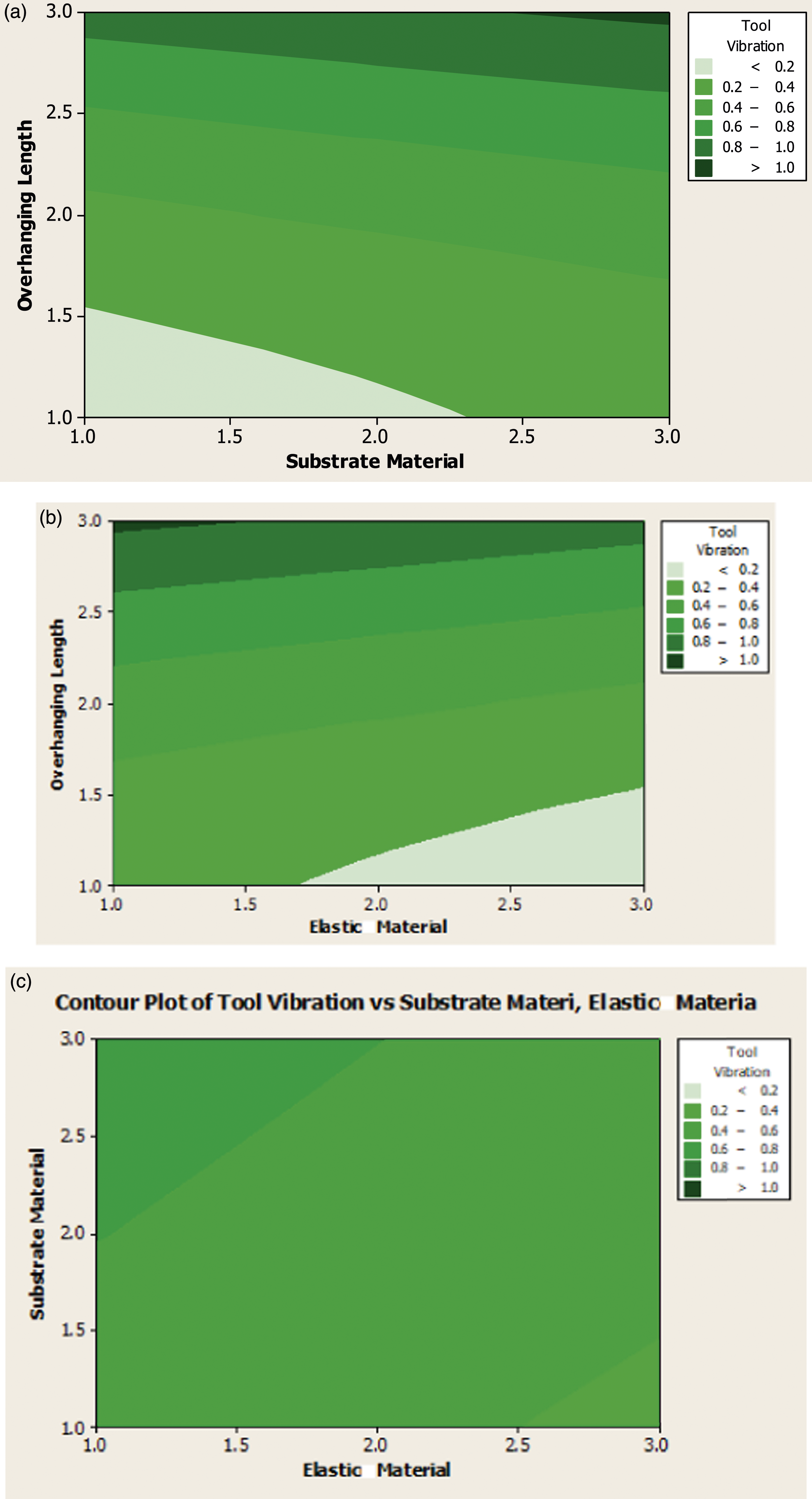
Tool vibration is significantly reduced when the overhanging length is at level 1 (100 mm) and the substrate material is copper. Conversely, high tool vibration is observed at level 3 (200 mm) with a substrate material of brass. Shorter overhanging lengths generally result in lower tool vibrations due to reduced leverage and increased stiffness. Copper’s higher damping capacity compared to brass contributes to the lower vibration observed. Lower tool vibration is seen at level 3 (100 mm) with polyurethane, while higher vibrations are observed at level 1 (200 mm) with natural rubber. Polyurethane, being an elastic material with good damping properties, effectively absorbs and dissipates vibrations. In contrast, natural rubber may not offer the same level of damping, leading to higher vibrations. Significantly reduced tool vibration when the constrained layer damper is made of copper and polyurethane. Copper’s damping properties, combined with the damping capabilities of polyurethane, create an effective system for absorbing and minimizing tool vibrations.
From Figure 10(a), surface roughness has significant reduction (1 – 1.5 μm) at the level 1 region of overhanging length (100 mm) and substrate material (copper). But surface roughness is substantial high (3–3.5 μm) at level 3 region of overhanging length (200 mm) and substrate material (aluminum). Similarly Figure 10(b), surface roughness is reduced (1–1.5 μm) at the interaction of level 3 of overhanging length (100 mm) and elastic material (polyurethane). But surface roughness is substantial high (3–3.5 μm) at level 1 region of overhanging length (200 mm) and elastic material (natural rubber). From Figure 10(c), surface roughness has significant reduction (1–1.5 μm) at level 3 region of substrate material (copper) and elastic material (polyurethane).But surface roughness is very high (3–3.5 μm) at level 1 region of substrate material (aluminum) and elastic material (natural rubber). Figures 10(a)–(c) show the results of the variable overhanging length, substrate material, and elastic material test for surface roughness. It was found that when the boring tool holder with a constrained layer damper made of copper and polyurethane, the surface roughness was significantly reduced. (a) Contour plot of surface roughness versus Substrate material and Overhanging length. (b) Contour plot of surface roughness versus Elastic material and Overhanging length. (c) Contour plot of surface roughness versus Substrate material and Elastic material.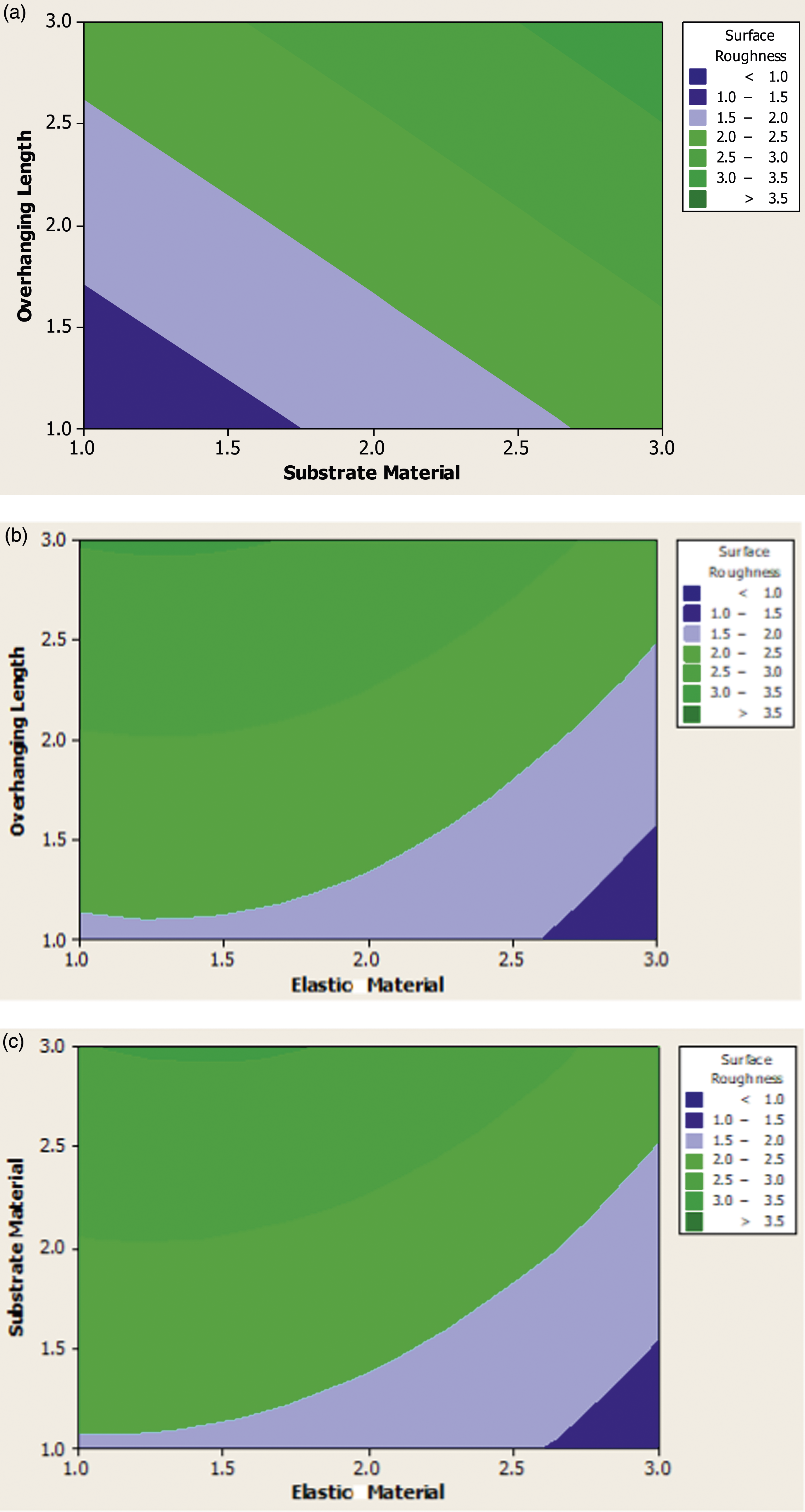
Substantial reduction in surface roughness at level 1 (100 mm) with copper, while high roughness is observed at level 3 (200 mm) with aluminum. Shorter overhanging lengths reduce vibration, leading to finer surface finishes. Copper, being softer than aluminum, might also contribute to lower tool wear and, consequently, reduced surface roughness. Reduced surface roughness at level 3 (100 mm) with polyurethane, higher roughness at level 1 (200 mm) with natural rubber. Similar to the effect on tool vibration, polyurethane’s damping properties contribute to smoother cutting, while natural rubber may lead to increased tool deflection and surface roughness. Significant reduction in surface roughness when the constrained layer damper is made of copper and polyurethane. The combined damping properties of copper and polyurethane contribute to minimizing tool vibration and, consequently, improving surface finish.
Based on the data presented in Figures 11(a)–(c), we observed notable variations in tool wear under different conditions. In Figure 11(a), it is evident that when the overhanging length was set at level 1 (100 mm) and the substrate material was copper, there was a substantial reduction in tool wear, with measurements consistently below 0.2 mm. Conversely, when the overhanging length increased to level 3 (200 mm) and the substrate material switched to aluminum, tool wear increased significantly, ranging from 1 mm to 1.2 mm. Moving to Figure 11(b), we noted a similar trend. When the overhanging length was at level 3 (100 mm) and the elastic material used was polyurethane, tool wear remained consistently below 0.2 mm. However, when the overhanging length was set to level 1 (200 mm)and natural rubber was employed as the elastic material, tool wear increased substantially, ranging from 1 mm to 1.2 mm. Figure 11(c) provided additional insights. Tool wear was notably reduced (ranging from 0.4 mm to 0.6 mm) when the substrate material was copper and the elastic material was polyurethane at level 3 overhanging length. Conversely, higher tool wear (ranging from 0.8 mm to 1 mm) was observed in most cases when the substrate material was aluminum and the elastic material was natural rubber at level 1. Overall, the analysis of Figures 11(a)–(c) demonstrates that the combination of a copper substrate material and polyurethane as the elastic material led to a significant reduction in tool wear. (a) Contour plot of tool wear versus Substrate material and Overhanging length. (b) Contour plot of tool wear versus Elastic material and Overhanging length. (c) Contour plot of tool wear versus Substrate material and Elastic material.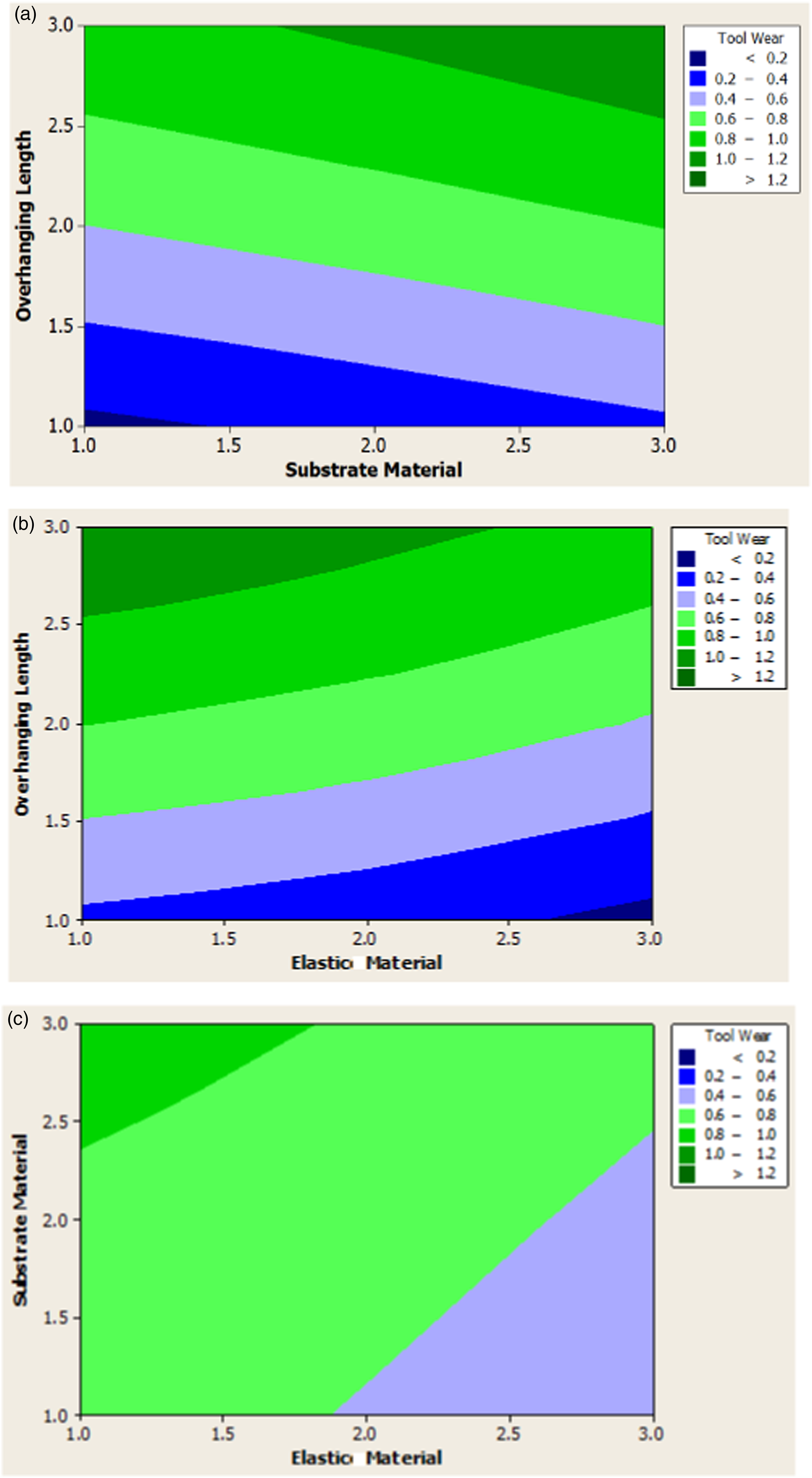
Substantial reduction in tool wear at level 1 (100 mm) with copper, significant increase at level 3 (200 mm) with aluminum. Shorter overhanging lengths reduce tool wear by minimizing deflection. Copper’s softer nature compared to aluminum also contributes to lower wear rates. Consistently low tool wear at level 3 (100 mm) with polyurethane, substantial increase at level 1 (200 mm) with natural rubber. Polyurethane’s damping properties reduce the impact forces on the tool, leading to lower wear. Natural rubber, being less effective in damping, results in higher wear rates. Significant reduction in tool wear when the constrained layer damper is made of copper and polyurethane. The combination of copper and polyurethane effectively dampens vibrations and minimizes wear, prolonging tool life.
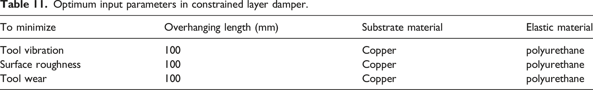
Optimum input parameters in constrained layer damper.
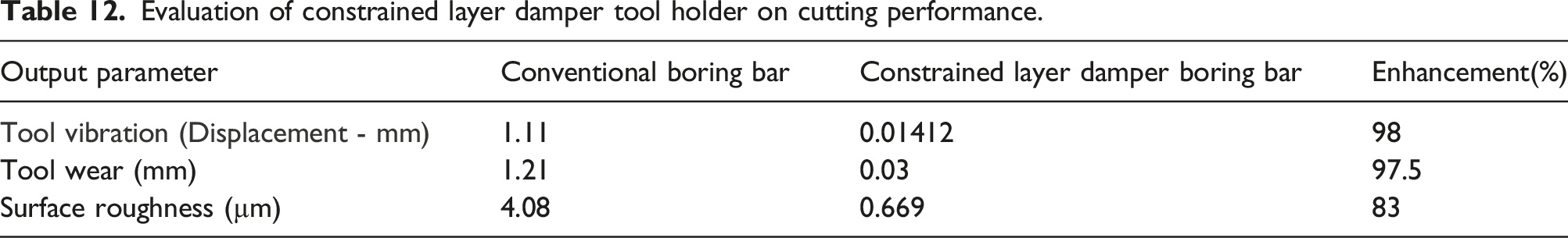
Evaluation of constrained layer damper tool holder on cutting performance.
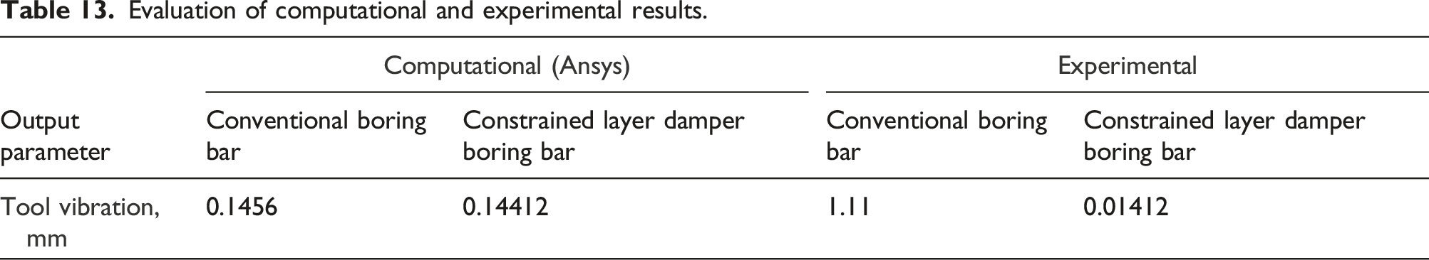
Evaluation of computational and experimental results.
The constrained layer damper has a stronger impact on damping than conventional passive dampers. The first is the constrained layer damper boring tool’s overhanging length, which is affected by tool bouncing, and the second is the substrate material, which is influenced by the material’s density and Young’s modulus. Tables 8–10 ANOVA study revealed that, when compared to substrate material and elastic material, overhanging length is the most important factor. The work takes into consideration substrate materials like copper, aluminum, and brass. When compared to aluminum (density 2713 kg/m3 & Young’s modulus 0.7 × 10⁵ MPa) and brass (density 8267 kg/m3 & Young’s modulus 0.9 × 10⁵ MPa), copper (density 8942 kg/m3 & Young’s modulus 1.23 × 10⁵ MPa) offers lower tool vibration, surface roughness, and tool wear. Young’s modulus and material density have an impact on the damping property of the substrate material. The overhanging length is the most important parameter, followed by substrate material and elastic material, according to Tables 8–10 ANOVA study. The work takes into consideration elastic materials including polyurethane, nitrile rubber, and natural rubber. When compared to nitrile rubber (density 75 kg/m3& Young’s modulus 1628 MPa) and natural rubber (density 100 kg/m3 & Young’s modulus 50 MPa), polyurethane (density 1265 kg/m3 & Young’s modulus 1880 MPa) offers decreased tool vibration, surface roughness, and tool wear. Here also the damping property of the elastic material is influenced by the density and Young’s modulus of the material. In constrained layer damping, the vibratory energy from boring bar is transferred to the substrate and elastic materials which are sandwiched. While the Young’s modulus and density of substrate and elastic materials remain high, the vibrating structure’s energy dissipated more efficiently by these materials which gets resulted towards reduction in tool vibration. 24 It is also noted that substrate material copper is efficient compared to aluminum and brass because the outer layer copper well sandwiched with boring tool and inner layer of the copper is well sandwiched with elastic material. Once the bouncing of tool (tool vibration) is reduced which in turn reduces the surface irregularities in workpiece and increases the tool life with less noise during the boring process. The computational analysis conducted in this study revealed that the constrained layer damper made of copper and polyurethane exhibited superior damping capabilities when compared to constrained layer damper made of other substrate and elastic materials. The mechanical properties of the constrained layer damper are determined by the combination of the substrate and elastic materials used. In this study, different combinations of copper, brass, and aluminum as substrate materials and polyurethane, nitrile, and natural rubber as elastic materials were tested. The results showed that the combination of copper and polyurethane provided the highest reduction in tool vibration during boring of hardened steel. This superior damping capability of the copper-polyurethane constrained layer damper can be attributed to the mechanical properties of the materials used. Copper material known for conductive and ductile ability provides excellent support to the viscoelastic layer, while polyurethane has excellent damping properties due to its high internal friction and better Young’s modulus. In contrast, the constrained layer damper made of other substrate and elastic materials tested in this study, such as brass, aluminum, nitrile, and natural rubber, exhibited lower damping capabilities. This can be attributed to their lower stiffness, lower damping coefficient, and better Young’s modulus when compared to copper and polyurethane. In summary, the computational analysis conducted in this study showed that the combination of copper and polyurethane provided the best damping capabilities for the constrained layer damper during boring of hardened steel. The results highlight the importance of careful selection of substrate and elastic materials in designing constrained layer damper for effective damping of tool vibration.
Conclusion
In this study, an attempt was made to investigate the effect of the Constrained Layer Damper on the cutting performance of hardened steel during boring process. The study involved designing, developing, and testing of constrained layer damper with varying overhanging length, substrate material, and elastic material to examine the effects of tool wear, surface finish, and tool vibration during boring of hardened AISI4340 steel.
The following inferences were arrived after the detailed study: • The Constrained Layer Damper demonstrated high effectiveness in reducing tool vibration, resulting in notable improvements in both tool life and surface finish during the boring of hardened AISI4340 steel. • Computational analysis revealed that the combination of copper as the substrate material and polyurethane as the elastic material provided the most significant reduction in tool vibration. This material combination was identified as the optimal choice for damping purposes. • Experimental results demonstrated substantial improvements in cutting performance with tool life experienced a remarkable enhancement of approximately 97.5%, surface finish exhibited a substantial improvement of approximately 83% and tool vibration witnessed a remarkable reduction of approximately 98%. • A meticulous comparison between computational predictions and experimental outcomes indicated a high degree of correlation. This alignment between the two sets of values underscores the accuracy and reliability of the computational method employed for the design and testing of the Constrained Layer Damper. • The Constrained Layer Damper emerged as an efficient and versatile damping method, showcasing its potential to significantly enhance the cutting performance of boring tools. The quantified improvements in tool life, surface finish, and vibration reduction underscore its practical application and positive impact on machining hardened steel.
Footnotes
Declaration of conflicting interests
The author(s) declared no potential conflicts of interest with respect to the research, authorship, and/or publication of this article.
Funding
The author(s) received no financial support for the research, authorship, and/or publication of this article.