
Abstract
The research on sound source identification in an infinite free sound field has been relatively in-depth, but there is relatively little research on sound source identification and localization in limited spaces, especially those with sound absorption and insulation materials. The identification and reconstruction of the acoustical steady propagation field radiated from a single frequency finite space are studied numerically using discrete elements based on the phase conjugation method by FEM. Two different kinds of array forms of phase conjugation arrays are studied for sound source localization such as the planar array and the linear array. In addition, the influences of the existence of sound-absorbing material on the wall on the focusing properties are also discussed. The numerical results show that: The phase conjugation method can completely achieve the identification and location of the acoustical source finite space no matter using the planar array form or the linear array according to FEM. The linear array form can obtain the subwavelength focusing with fewer elements. The optimal distance between the array and the sound source is 0.5
Keywords
Introduction
When sound waves radiate, they are divided into free sound fields, semi free sound fields, and finite space sound fields based on the properties of their propagation space. 1 In a free sound field, sound waves radiate from the sound source towards the surrounding space and are not reflected or scattered by boundaries or other objects. The sound pressure of the radiated sound waves is inversely proportional to the distance from the center of the sound source. And the sound intensity is inversely proportional to the square of the distance.
In reality, many noise sources’ radiation sites are located in bounded spaces, such as acoustic measurements in reverberation limited spaces, speeches in halls, radiation from machine noise in factory workshops or in the cabins of ships, planes, cars, and other means of transportation. Due to the presence of walls in limited space, sound waves must be reflected to form standing waves, which make the sound field in limited space quite complex. In addition, if the acoustic properties of the wall are not uniform everywhere, the shape of the room is irregular or there are other scatterers in the limited space, it makes the general limited space sound field more complex. There are two different phenomena in the propagation of sound waves in finite space compared to in a free field. Firstly, due to the continuous reflection of sound waves from the wall, when the sound source stops, there is still continuous sound waves in the finite space, which means that a standing wave field will be formed in the finite space. Secondly, due to the continuous reflection of the wall surface, in addition to the sound energy provided by the sound source radiation, additional sound energy will also be provided by reverberation 2 in a limited space.
There are currently two main methods for calculating the propagation of sound waves in the general finite space sound field mentioned above, which are wave theory 3 and ray acoustics. 4 With the development of computer technology and signal processing technology, the indoor sound field simulation technology is gradually mature. The geometric acoustic virtual source method, sound line tracking method, and the hybrid method of the two are only suitable for the simulation of the high frequency part of the indoor sound field. For the low-frequency part of the indoor sound field and small indoor space, the wave effect of the sound wave is more significant, such as the diffraction and interference phenomenon of the sound wave, the room mode, or the resonance effect, which can be used to simulate by the wave acoustic method. The commonly used indoor sound field simulation methods based on wave acoustics include finite element method (FEM), boundary element method (BEM), finite difference time domain method, and digital waveguide grid method (DWM). 5
Acoustic properties for different systems: GUAN 6 studied acoustic damping performances of double-layer in-duct perforated plates at low Mach and Helmholtz number to evaluate the effects of the porosities of the front and back plates, and the axial distance between these two plates. Zhao dan 7 et al. studied the aerodynamic acoustic damping performance of the inner orifite of a double-layer pipe, and further noise absorption can be achieved by introducing an additional layer of inner orifite of the pipe. Ref. [8] measured the aerodynamic acoustic damping performance of 11 perforated plates in a cold flow pipeline with variable Mach number. These plates had the same porosity, but the number and geometry of the orifice were different. The results showed that the shape of the orifice plate had little effect on the power absorption. Mohammad Ghafouri 9 developed an analytical strategy to take into account the theory of three-dimensional elasticity, proposing the vibrational acoustic behavior of sandwich plate structures under 3D-RACS. The state vector method is used to divide the structure into several layers and the global transfer matrix method is applied to all layers of the structure. Mohammad Hossein Asadi Jafari 10 studied the acoustic performance of double-curvature sandwich shell structures with various truss cores based on diffusion field. Compared with single-layer sandwich shells without trussed cores, double-curved sandwich shells with trussed cores enhance the incident sound transmission loss in the entire frequency domain and transfer the curvature frequency to a lower frequency. M. R. Zarastvand 11 gives some explanations of the importance of the subject and the basic equations of the problem, according to all the work in the field of wave propagation through plate structures collected in various categories. Ref. [12], a comprehensive source under the title of review papers, discusses all existing articles on the acoustic properties of multilayer panel structures and analyzes the amount of sound transmitted to the structure.
The famous acoustician Morse introduced the theory of normal modes into finite space acoustics and obtained the solution of forced vibration in finite space based on the wave equation. Over the past few decades, this theory has had a profound impact on the study of steady-state sound fields in finite space.13–15 For several bounded spaces with regular shapes, such as rectangles, spheres, and columns, strict theoretical solutions can be obtained through wave acoustics. However, for spaces with complex shapes or spaces with certain requirements for boundary conditions, this method is not applicable. And ray acoustics is based on the assumption of energy averaging and is only suitable for high-frequency calculations, which is not suitable for calculations in large low-frequency spaces. In order to solve the distribution of sound field in finite space under complex room shapes and boundary conditions, many scholars have begun to introduce the finite element method into the study of finite space acoustics.16–18 At present, the application of finite element in finite space acoustics is mainly applied to steady-state fields, such as ship radiated noise, 18 vibration and noise analysis of automobiles, 19 and acoustic modal analysis in steady-state fields. Ref. [20] establishes a finite element model of the sound field for high-strength focused ultrasound based on the sound wave equation and its boundary conditions.
The noise source identification technology is of great significance in structural noise control and acoustic fault diagnosis. Choosing a reasonable noise source identification technology is crucial, 21 especially for the sound source identification technology of a steady-state sound field in a limited space. Lochner, J.P.A. 22 et al studied the relationship between speech articulation and signal-to-noise ratio and obtained that the signal-to-noise ratio can reflect the relationship between speech articulation and reflected sound. He pointed out that the comprehensive use of direct sound and early reflected sound of speakers can improve speech articulation. Craggs 23 established an acoustic finite element model to analyze the sound field in a finite space with irregular shape. Petyt 24 discussed the internal sound field formed by the vibration of a cylindrical shell under force excitation. Richards analyzed the internal sound field of a car and conducted a car model test. 25 Nefske uses direct method and modal superposition method to solve the problem of acoustic-solid coupling in vehicle interior and carries out an example analysis. Ma Dayou once pointed out that in the classical theory of finite space sound fields, there is only normal mode reverberation sound and no direct sound, which is not in line with reality. 18 His research shows that in normal mode theory, sound sources have a dual role: sound sources radiate sound waves in free space and remain unchanged as long as they do not encounter the walls or boundaries of the room. After the free radiation reaches any boundary, it is reflected on the wall as a series of wavelets with irregular distribution in time, space, and direction. And the source of the wavelets can be traced back to the sound source. These wavelets continue to propagate and reflect, ultimately forming standing waves that are allowed in a finite space which is normal modes. So the sound source is both a direct source of sound waves and a source of standing waves in limited space.
The phase conjugation (time reversal) method 26 is a new discipline developed in recent years, which can achieve reverse propagation and adaptive focusing of sound waves and be used for sound source localization. 27 This is mainly due to the good robustness and temporal stability of the time reversal method. This method for identifying and locating sound sources in ocean waveguide media has advantages that cannot be compared to other positioning methods.
Peter Blomgren and George et al. 28 proposed that because of the non-uniformity of the ocean medium and the presence of ocean interfaces, multi-path channels can achieve high-resolution sound source localization results. Jackson and Dowling 29 have demonstrated that time reversal in the time domain is equivalent to Phase Conjugation (PC) in the frequency domain that is also a forward propagating sound field, and a backward propagating sound field. According to the above theory, there is also a multi-path phenomenon of sound waves reaching the measurement array in a finite space sound field due to wall reflection, which is very similar to the propagation of sound waves in ocean channels. Therefore, the phase conjugation method can be fully applied to finite space sound field for sound source identification. Cai Yefeng et al. 30 studied the feasibility and mechanism of the application of time reversal method in complex sound field microphone array pickup. He provided general rules and performance. This paper uses finite element method based on the principle of phase conjugation to identify and locate a single frequency sound source in a steady-state sound field in a finite space. Two different array forms are used for sound field measurement and conjugation and forming a focus at the sound source, namely, linear array and planar array. In addition, this paper also explores the influence of the presence of sound-absorbing materials on the phase conjugation focusing characteristics of the wall.
Theory
Acoustical FEM in the room
In the volume V, surface S of the closed space, the sound source was assumed to simple harmonic motion, and the active acoustic wave equation in the room is
31

The acoustic absorption condition is

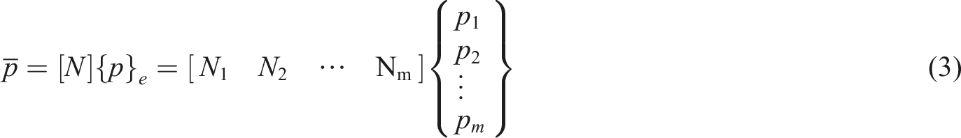
The sound field space V was disserted into a number of units. For any unit, the sound pressure p at any point within the unit could be represented by the sound pressure nodes
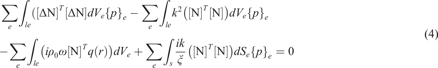


Then equation (4) can be expressed as


Since the absorption of air is not taken into account, only the units on the boundary contribute to
Phase conjugation method
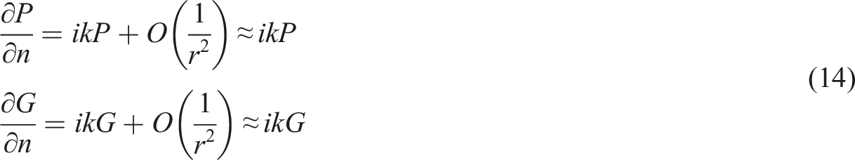
The reason why the time reversal method can realize the back propagation and adaptive focusing of sound wave is that the linearized wave equation (1) only contains the second derivative of sound pressure with respect to time, so


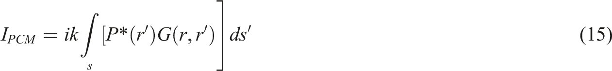
The PCM method for calculating the phase conjugate sound field based on the monopole sound source can be obtained by the simultaneous above formula
The PCD method based on the phase conjugate sound field of the dipole source is

The numerical calculation steps of sound source identification in finite space steady-state sound field using phase conjugation method are as follows: (1) For the positive sound field problem, the sound pressure value or the sound pressure gradient at the phase conjugate measurement array is calculated by the finite element method; (2) Conjugate values of the sound pressure or sound pressure gradient of the measurement array are substituted into the acoustic governing equation as known boundary conditions of sound pressure, and finally focus is realized at the sound source.
Numerical simulations
The feasibility of identification and location the sound source by using phase conjugation method was realized in the size of 5.0 m * 4.0 m * 3.0 m room as the example. The coordinate origin was taken as the geometric center of the room. Tetrahedral grid was used for room division, containing 68,673 domain units, 4004 boundary units, and 204 side units. The maximum cell size was 0.09 m, the minimum cell size was 0.09 m, the maximum cell growth rate was 1.5, the mesh curvature factor was 0.6, and the narrow area resolution was 0.5. According to the fluid unit limit of 6 units in one wavelength, sound source located at the point (−1.9, 0, 0) and sound pressure amplitude was unit. All walls in the room were taken as rigid walls. The sketch of the room is shown in Figure 1: The diagram of the acoustical field in the room and the measurement array.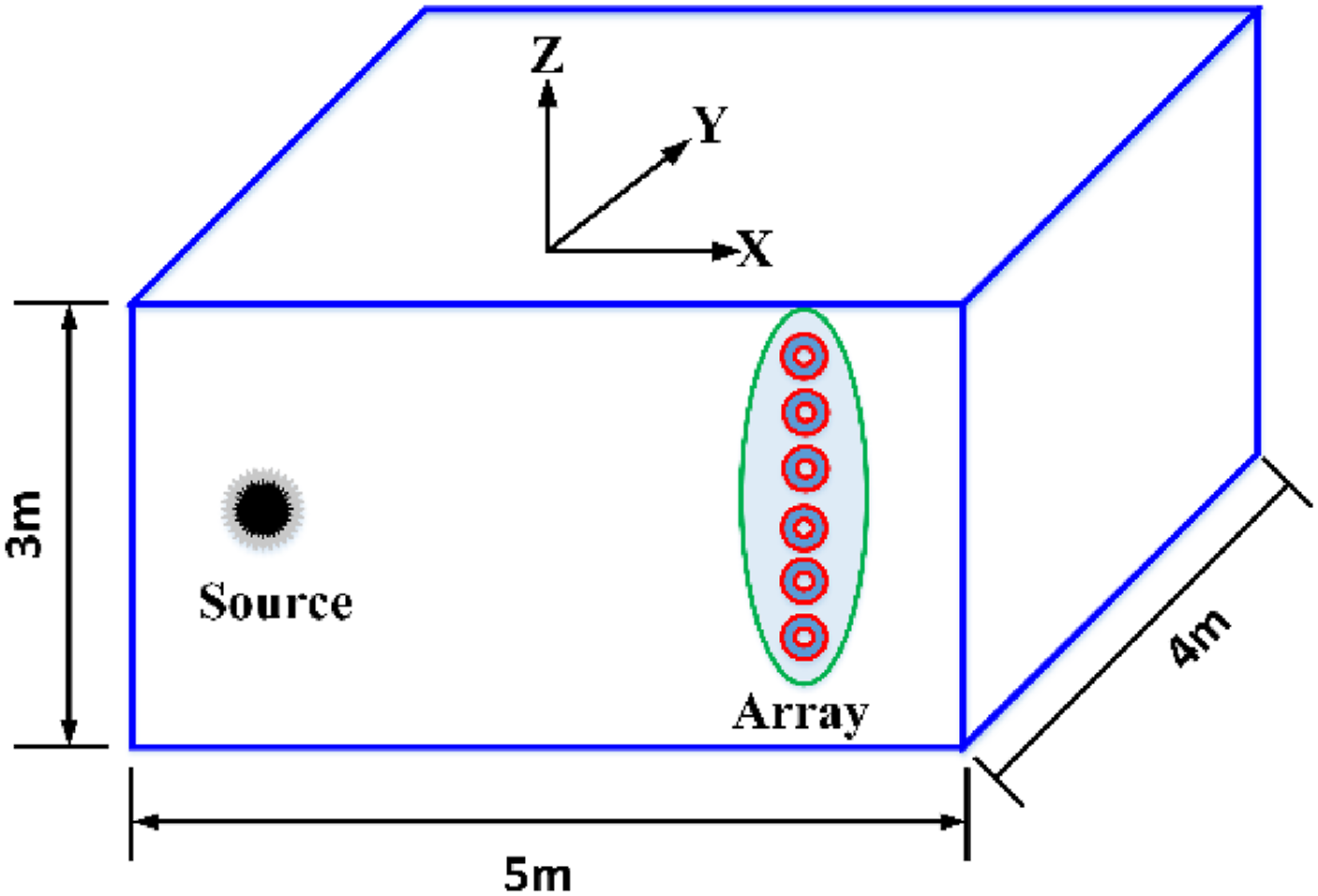
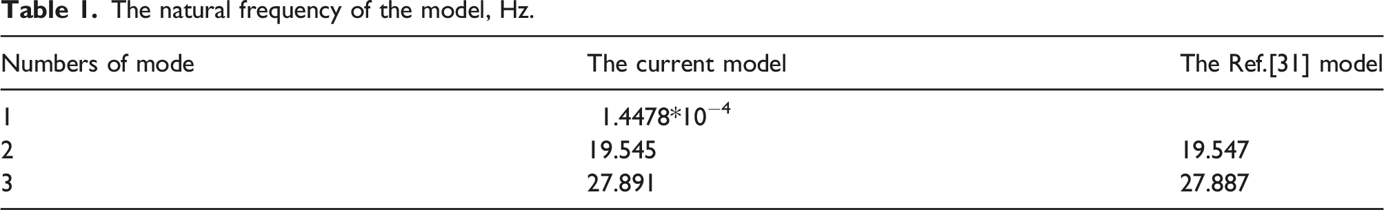
The natural frequency of the model, Hz.
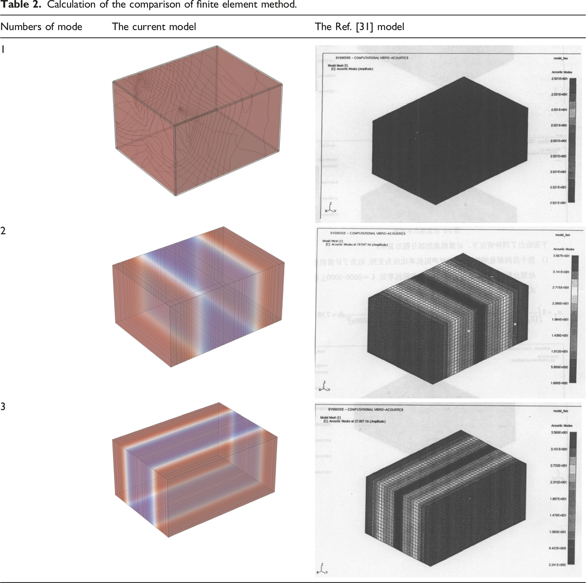
Calculation of the comparison of finite element method.
The natural frequency of the room acoustic cavity.
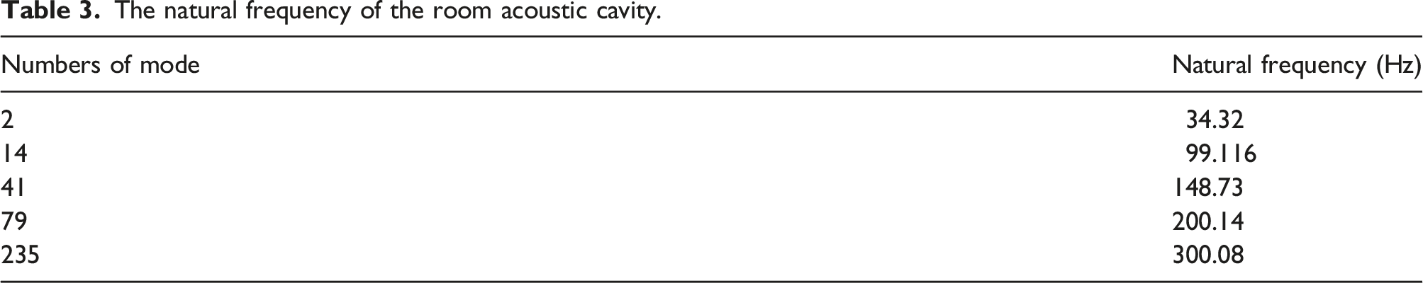
According to the calculation, the natural frequencies under different modes are obtained. The speed of sound in air is 340 m/s. The calculated frequency is f = 300 Hz corresponding to the 235th modes, then the corresponding acoustic wavelength The mode shape corresponding f = 300 Hz.
Under the soft sound field boundary condition, the natural frequency sound pressure distribution map when f = 300 Hz is shown in Figure 3: The outdoor sound field sound pressure distribution map f = 300 Hz.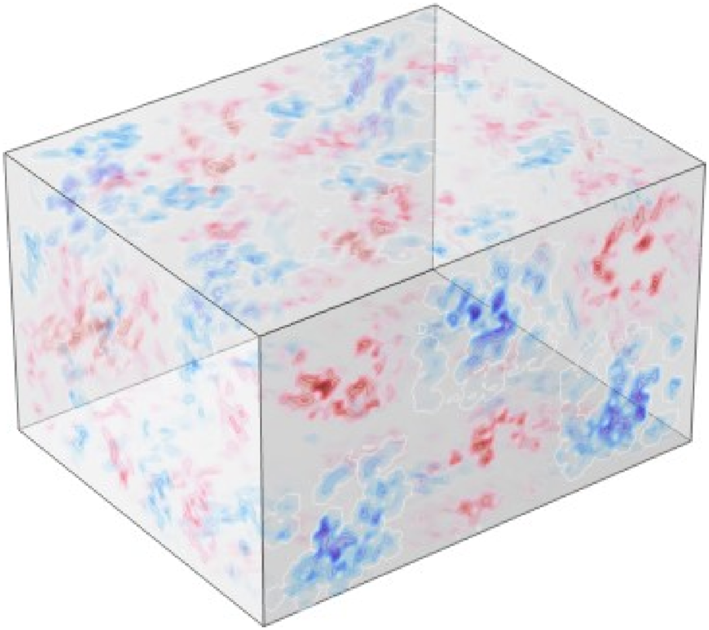
Another sound source is added at a symmetric position with the existing sound source, and is introduced as information to simulate background noise. When the noise source and the original sound source are both 1 Pa, the resulting sound pressure distribution map is shown in Figure 4. Distribution map of sound pressure when both sound sources are 1 Pa.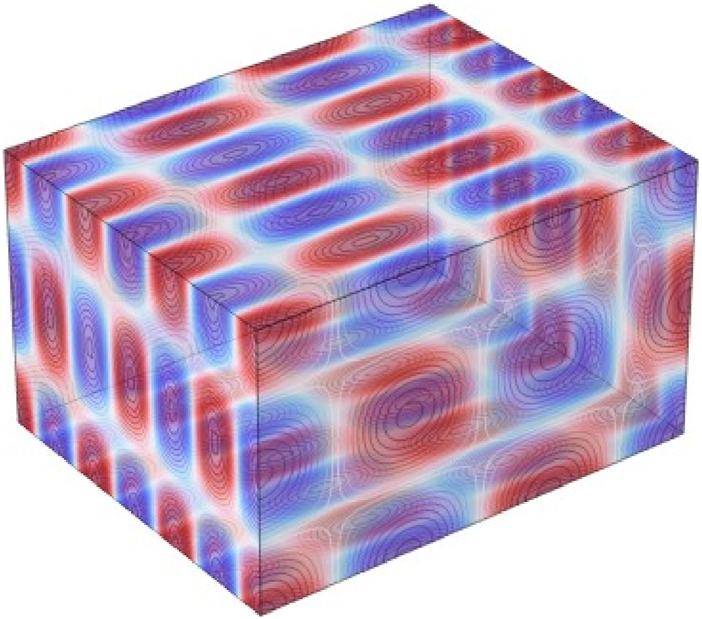
Different array forms
The phase conjugation methods were used to identify and locate sound source in the room. First, the sound pressure level of the array calculated by FEM and took the conjugate value then re-emitted into the sound field and focus at the position of the focus source.
Consider the planar array form
The distance between the planar array and sound source was 0.5
Consider the source location, that is, the intersection line of X = -1.9 m and plane Z = 0 plane. Figure 5 shows the sound amplitude field distribution of the source (dB), and Figure 6 shows the reconstructed sound field amplitude distribution by the planar array based on the phase conjugation method. The source pressure amplitude distribution at the cross line. between the plane X = −1.9 and Z = 0. The reconstructed pressure amplitude distribution with the planar array.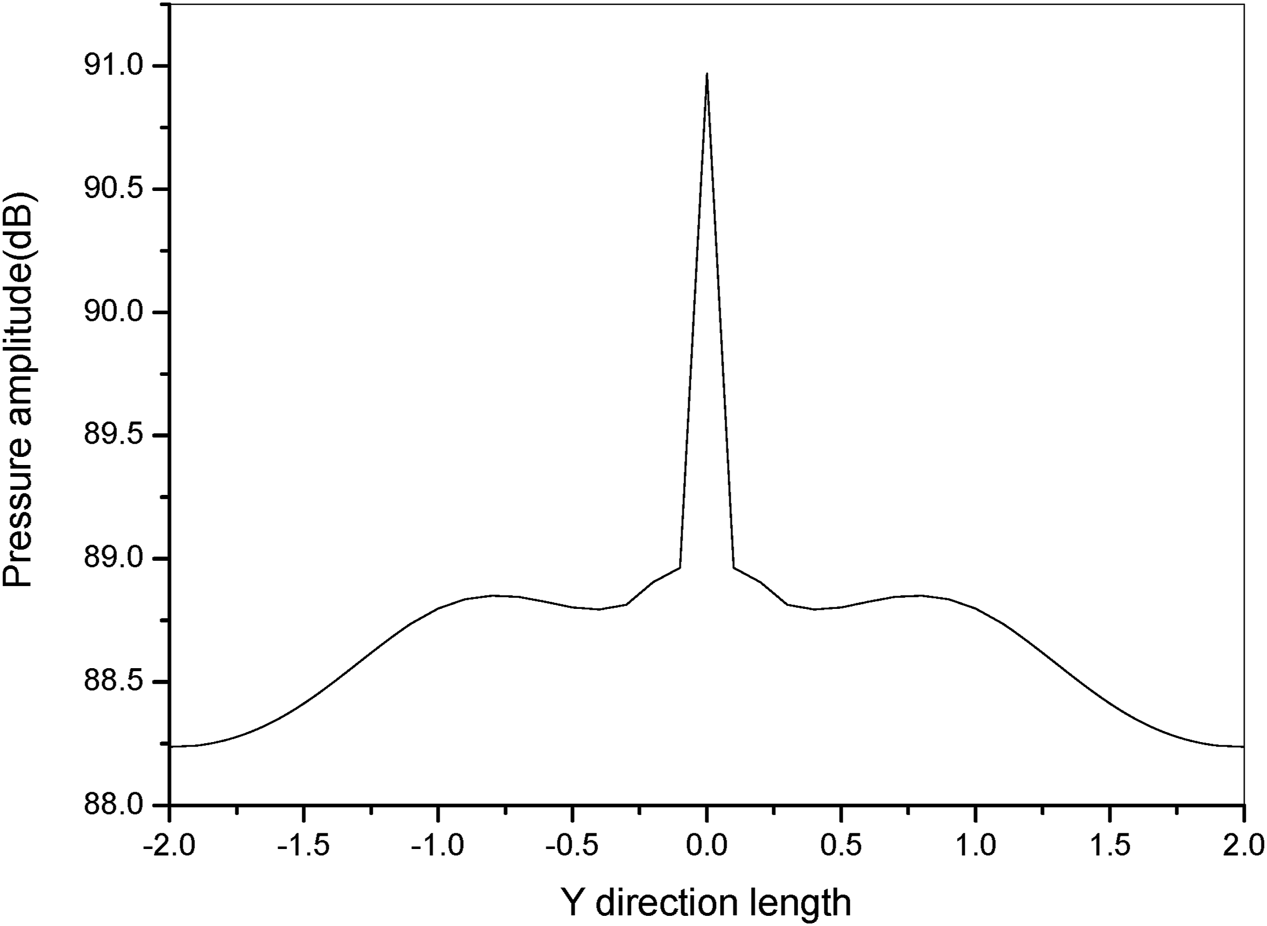
Consider the form of a line array
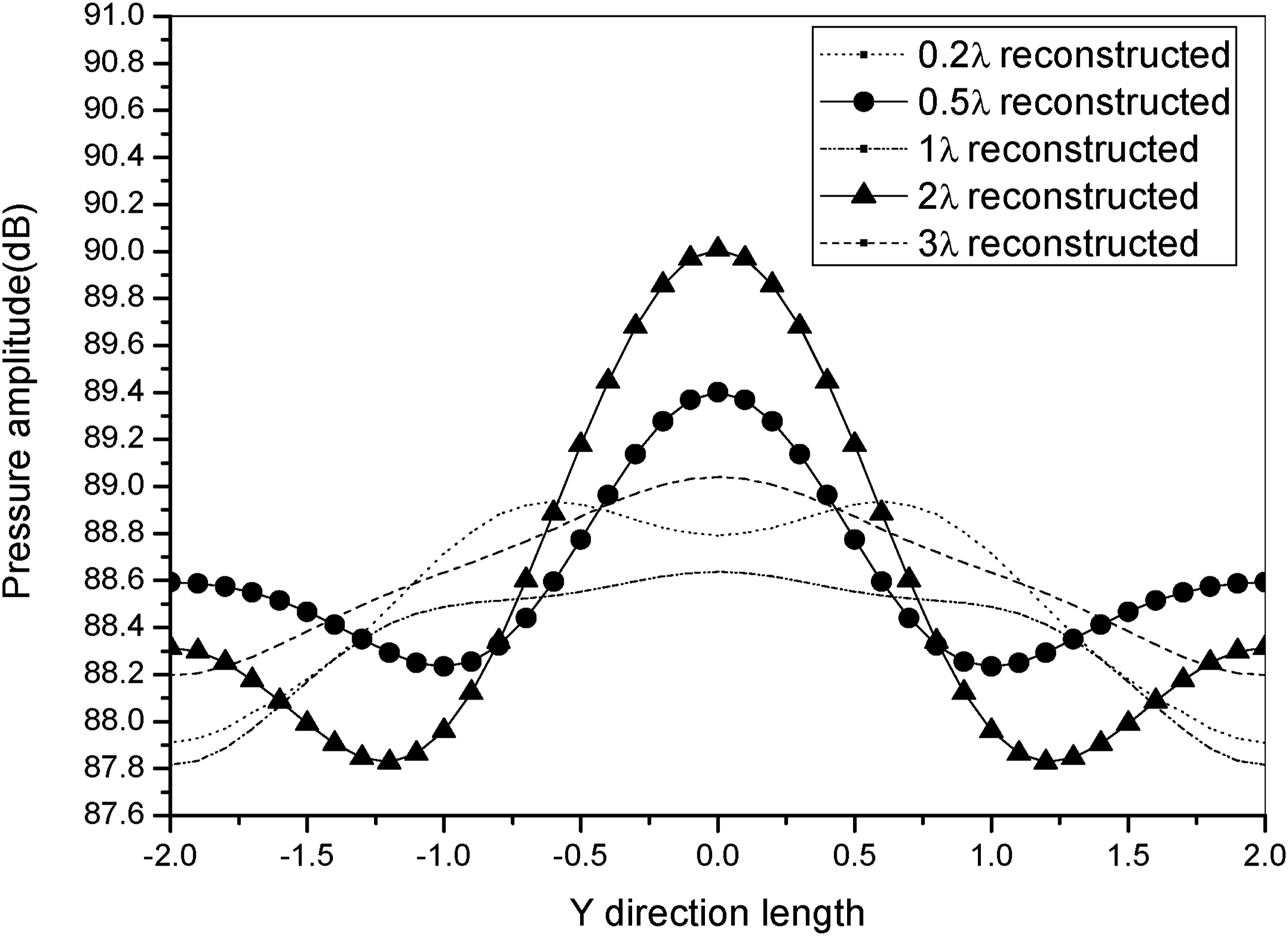
The line array is located on plane Z = 0. The distance between the linear array and the sound source in the X direction is also taken as 0.2 The reconstructed pressure amplitude distribution with the linear array.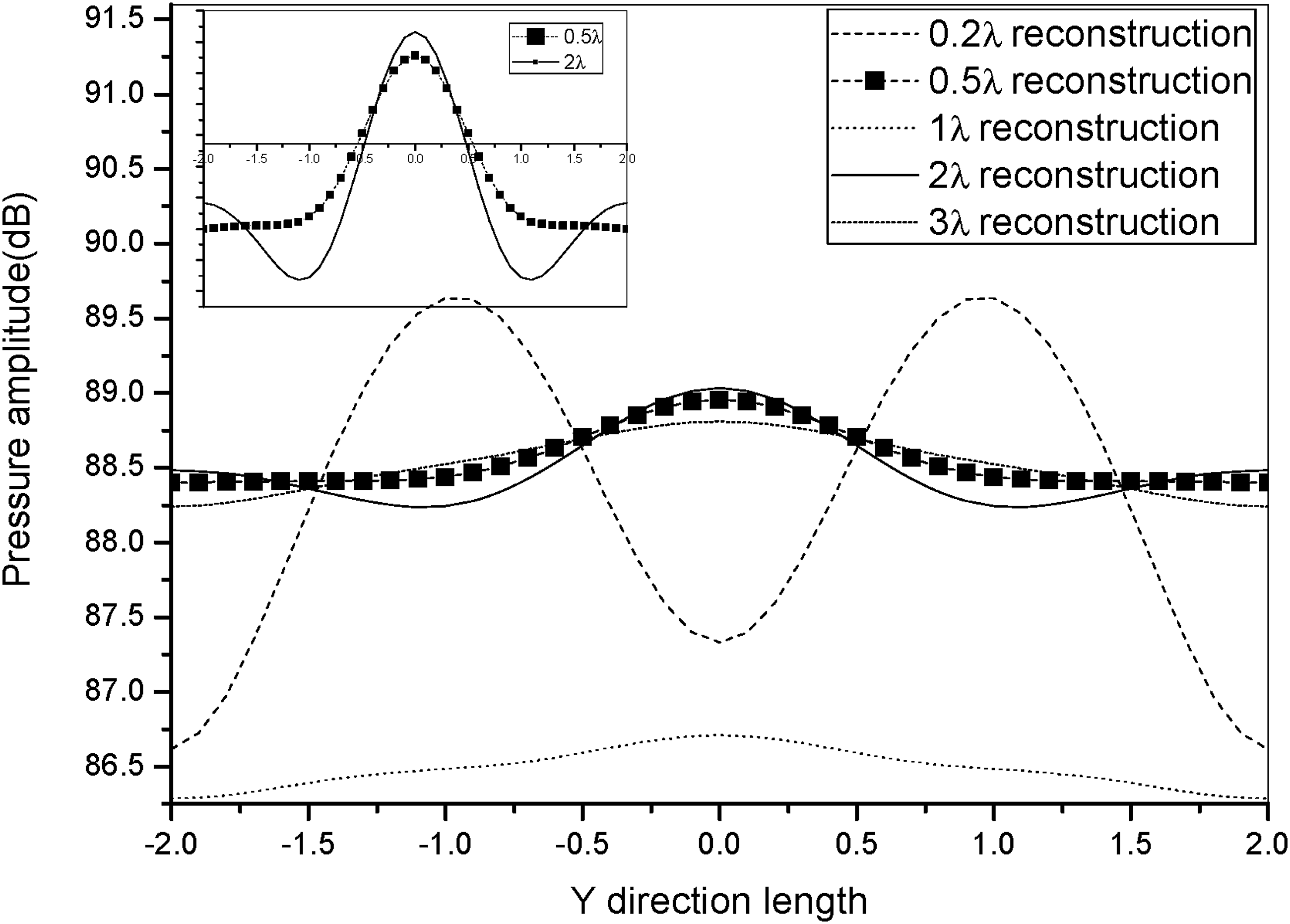
The sound source location and identification could be obtained by using phase conjugation method as seen from the results in Figures 6 and 7, and the perfect reconstruction results were obtained at the distance between the array and source of 0.5
Wall laying of sound-absorbing materials
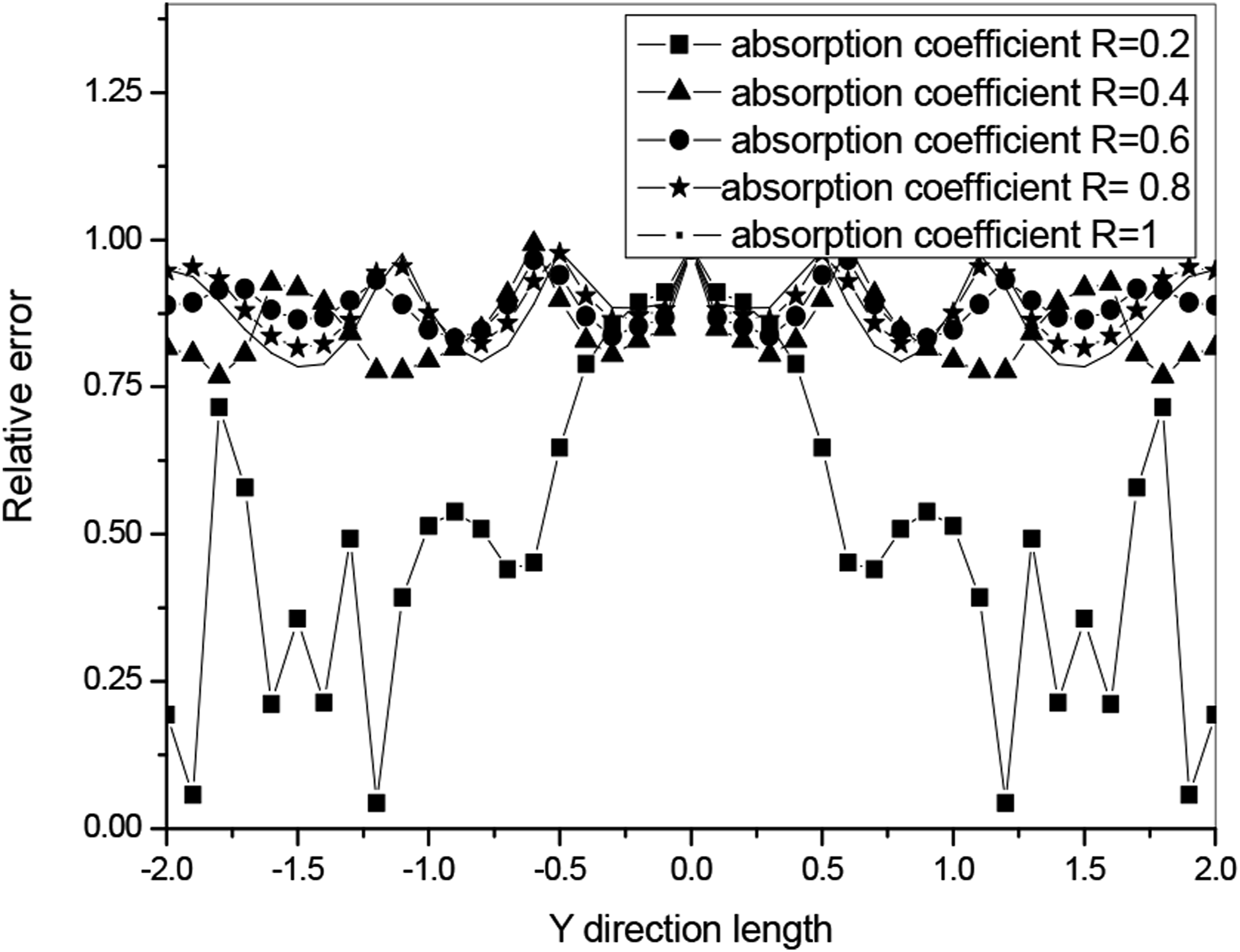
The above conclusions were obtained by assuming the six walls of the room to be rigid, and identifying and reconstructing the sound field distribution in an ideal state. In practical life, reinforced concrete walls have sound-absorbing properties, and materials with sound-absorbing properties are laid on ceiling panels and floors. Therefore, it is necessary to study the impact of phase conjugation method focusing characteristics when laying sound-absorbing materials on the wall surface. Considering the situation where the sound absorption coefficients of the six walls of the room are the same, the sound field distribution diagram is given in Figure 8 when the sound absorption coefficients are 0.2, 0.4, 0.6, 0.8, and 1, respectively. Figure 9 shows the relative error comparison curves of the reconstructed values of the sound pressure amplitude at the intersection of plane X = −1.9 m and plane Z = 0 using the phase conjugation method when the sound absorption coefficients are 0.2, 0.4, 0.6, 0.8, and 1, respectively. The array form is taken as a linear array, with a distance of 0.5 Distribution map of sound pressure under different absorption coefficients. The relative error comparison curve source of the pressure amplitude distribution at the cross line between the plane X = −1.9 and Z = 0.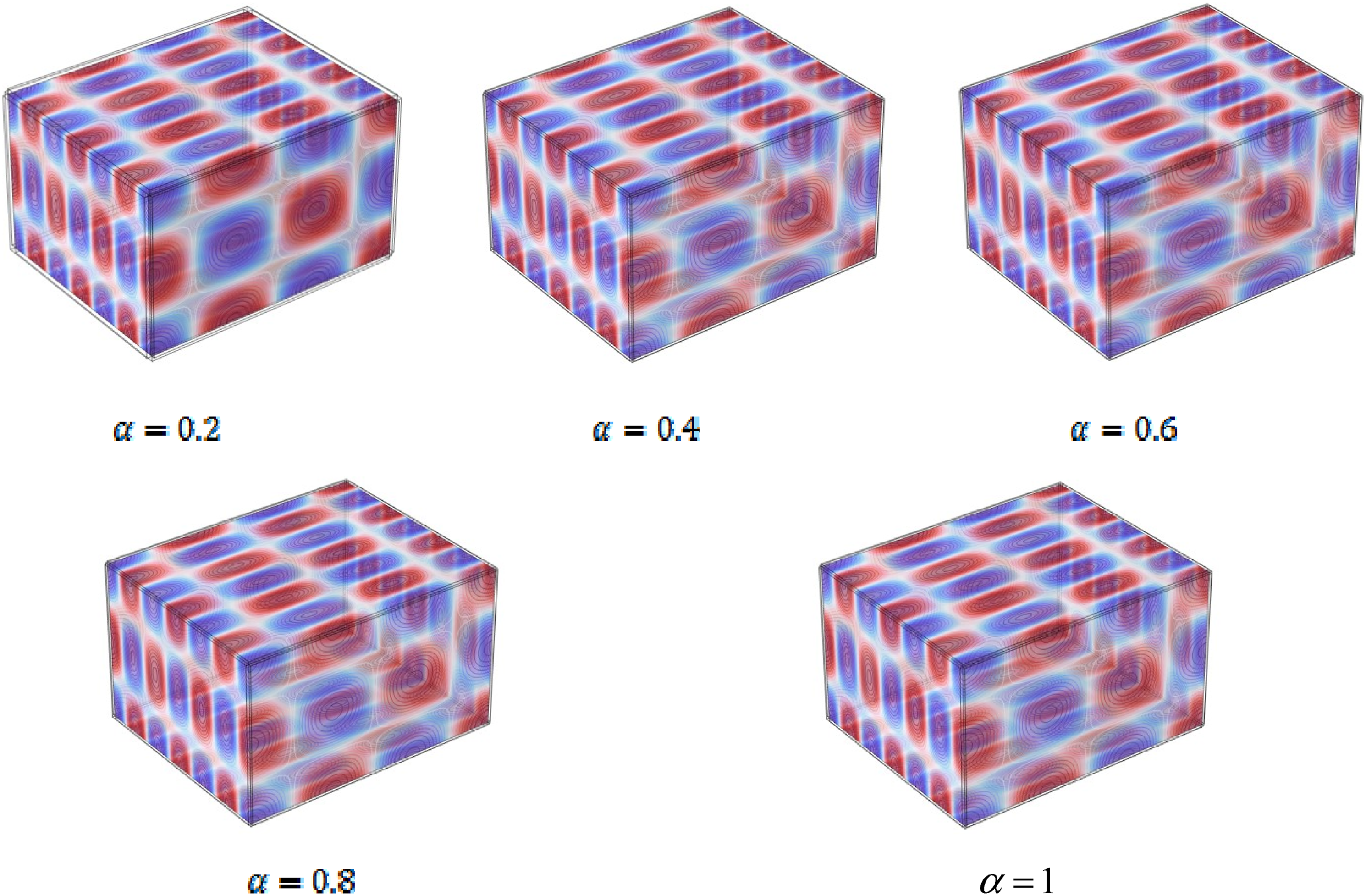
The relative error is defined as
Among them,
From the results in the above figure, it can be seen that the closer the wall is to rigidity, that is, the smaller the sound absorption coefficient, the larger the surface sound pressure, and the smaller the relative error of the reconstructed value, resulting in a better reconstruction effect of the sound source. This is because the closer the wall is to the rigidity, the more complex the path of sound propagation, and the more it satisfies the principle of multi-path phase compensation using phase conjugation methods. When the sound absorption coefficient is set to 1, the sound field is a free field, and the sound waves emitted by the sound source are completely absorbed after propagating to the wall. At this point, the reconstruction relative error obtained is large. The phase conjugation method is very effective for solving the problem of multi-path propagation in sound fields.
Conclusions
This article uses finite element method based on the principle of phase conjugation to identify and locate sound sources in a steady-state sound field in a finite space. Two different array forms, namely, linear array and planar array, are used for sound field measurement and conjugation, forming a focus at the sound source. In addition, this article also explores the influence of the presence of sound-absorbing materials on the phase conjugation focusing characteristics of the wall. The numerical calculation results show that using the finite element method, both planar array and linear array based on phase conjugation method can fully achieve sound source identification and localization in a finite space steady-state sound field, while using the linear array form can identify the position of the sound source with fewer array elements. The sound source localization effect is best when the distance between the array and the sound source is 0.5
Footnotes
Declaration of conflicting interests
The author(s) declared no potential conflicts of interest with respect to the research, authorship, and/or publication of this article.
Funding
The author(s) disclosed receipt of the following financial support for the research, authorship, and/or publication of this article: This work was supported by the Project of the National Natural Science Foundation of China: Research on the Separation and Identification of Multi target Noise Sources in Complex Sound Fields Based on Phase Conjugation Method (No. 51609037); Basic Research Business Fee Project of Dalian University of Technology: Research on Location and Imaging of Ship Radiated Noise Sources in Complex Marine Environment (No: DUT22GF206).