
Abstract
At present, most of the turbofan engine use the articulated link mount to connect the engine to the wing. The mechanical modeling, analysis and experimental research of articulated link mount are important means in the development of engine mount. In this paper, multibody dynamics method is used to establish the dynamic theory equation for a certain type of turbofan engine mount, and the low-frequency approximation method of the MNF file is proposed, which greatly improves the calculation speed on the basis of ensuring the calculation accuracy. In addition, a full-scale engine mounting system vibration isolation performance test platform was developed, and the vibration isolation efficiency of a certain type of engine mount at the high and low pressure rotor frequency was obtained. The results show that the simulation and test results agree well, the error is within 15% at the low-frequency, and 5% at the high-frequency. This work provides theoretical method and test evaluation means for the design and improvement of large passenger aircraft engine installation devices.
Keywords
Introduction
As one of the main vibration sources of aircraft, the installation of aircraft vibration reduction is an important measure for aircraft vibration control, especially to improve the vibration environment in the cabin.1–4 Civil Aviation of China CCAR-25 and U.S. Civil Aviation FAR-25 both clearly stipulate that in order to reduce the response caused by engine vibration, the engine installation device should take vibration reduction measures.
In the eighties and nineties of last century, Airbus and Boeing successively used articulated link mount on the main narrow-body passenger aircraft to replace the installation method with special vibration isolation devices, using the low stiffness of such mechanisms to achieve the effect of vibration reduction/isolation, while improving structural reliability, representative models include B737NG, A320, etc. From the perspective of the development of foreign turbofan engine installation sections, turbofan engines have been accompanied by significant technological progress from the initial “rigid connection” to the “high-reliability installation section” adopted today. The mechanical modeling, analysis and test verification of the articulated link mount are important technical means in the development process of the mount.5–10
Due to the late start and insufficient technology accumulation in the development of engine mount in China, there are currently no self-developed products used in the model, mainly purchased with engine products. In recent years, China has gradually realized the importance of engine mount, and has successively carried out related research. In terms of simulation analysis, most studies are based on the finite element model for load strength analysis of airframe and engine mounting,11–15 while there is relatively little analysis of the dynamic characteristics for the entire “engine-mount-wing” system. However, the research on engine vibration transmission is still limited to simulating engine vibration characteristics with a concentrated mass model, and using the overall finite element method to calculate the static bearing characteristics of the engine mount,16–19 which is a simple model and isolated design that is outdated for modern aircraft. In terms of experimental research, it is also mainly focused on a small number of static tests or scaling test,20–22 and the vibration isolation performance test of the full-size engine installation section has not yet been carried out, which is not enough to support the independent development of China’s turbofan engine mount. Therefore, there is an urgent need to develop a “fast and precise” dynamic analysis technology for engine mounting and to develop relevant experimental platforms to form the testing capabilities of dynamic performance of engine mounting. This will provide analytical tools for the design and improvement of large passenger engine mounting in China and provide experimental basis for their design and finalization.
Taking multibody dynamics as the research method, this paper established the kinetic theoretical equation for the mount of a turbofan engine, and proposes a low-frequency approximation method for MNF files, which greatly improves the calculation speed on the basis of ensuring the calculation accuracy. At the same time, a full-scale engine mounting system vibration reduction performance test platform was developed, and the vibration isolation efficiency of a certain engine mounting joint at the high and low pressure rotor frequency was obtained. The relevant research results can provide analysis means and test basis for the localization of the mount of large passenger aircraft in China.
Taking multibody dynamics as the research method, this paper established a dynamic theoretical equation for the full-scale mounting of a turbofan engine for the first time, and proposes a low-frequency approximation MNF rigid-flexible coupling dynamic modeling method. Compared to the complete MNF rigid-flexible coupling modeling method and the full rigid body modeling method, it significantly improves the computational efficiency while ensuring the accuracy of the calculation. At the same time, based on the four-terminal parameter method of vibration transmission system, a dynamic performance verification platform for the full-scale engine mounting system was first developed and built. The engine imbalance vibration load was loaded through the self-developed engine simulation piece-rotating excitation tester, and the vibration isolation efficiency of a certain engine mounting joint at high and low pressure rotor frequencies was obtained. The relevant research results can provide analytical methods and experimental basis for the localization development of engine mounting joints for large passenger aircraft in China.
Overview of the engine mounting
Main structure
The engine crane installation system model studied in this paper mainly consists of three parts: engine simulator, mount and hanging simulator. Among them, the engine simulator is a single rigid body model, which mainly applies static load and excitation load to its center of mass to simulate the thrust load and vibration excitation under the normal operating conditions of the actual engine. The mount is a multi-rigid body mechanism, which connects the engine simulator and the hanging simulator, and has the effect of transferring load and isolating vibration at the same time. The hanging simulator is a single rigid body model, fixed with the ground, and is a fixed part of the entire system.
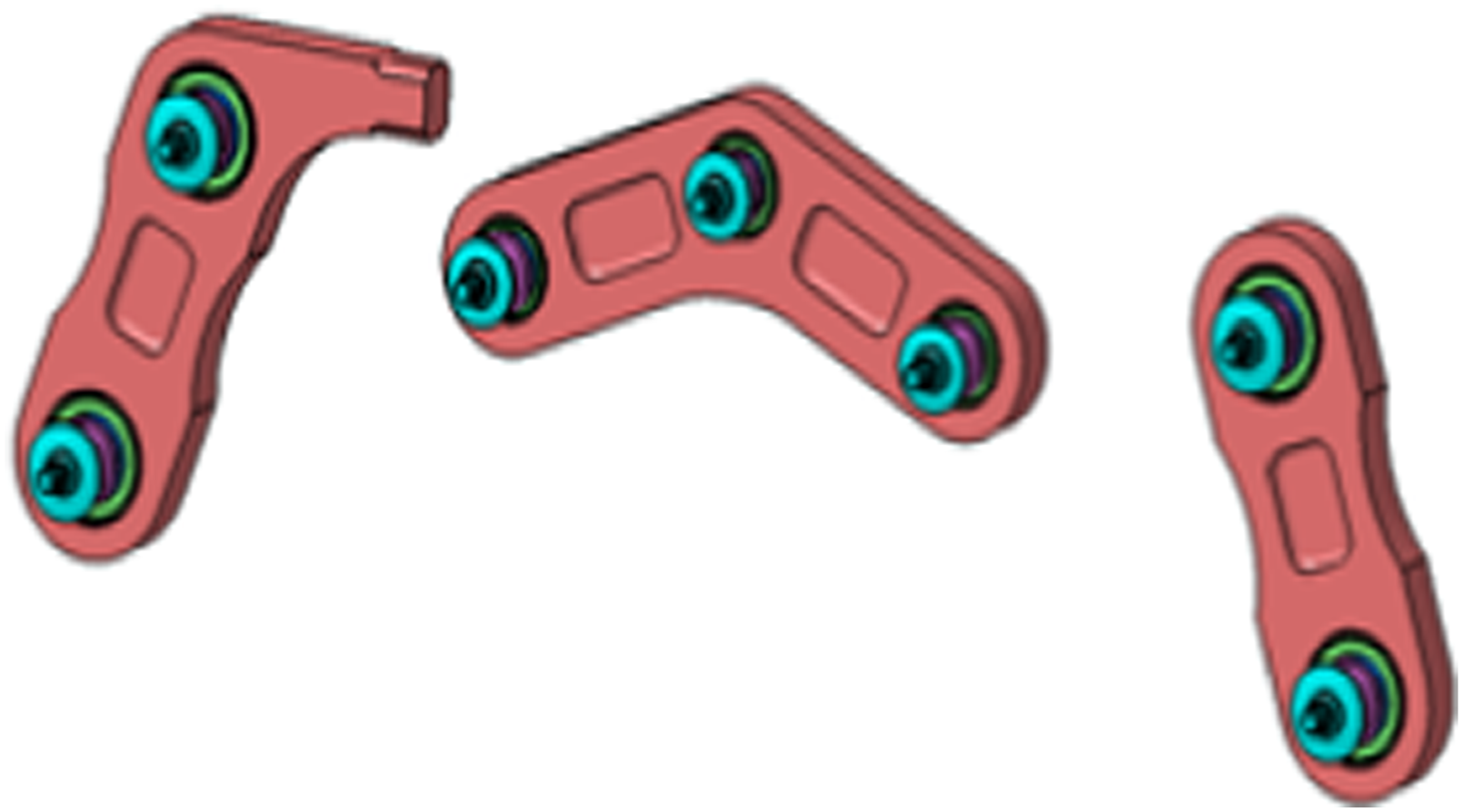
Among them, the engine mount part can be subdivided into two parts according to the role of the mechanism: the front mount and the rear mount (including the thrust rod). The connection relationship between each part and the engine simulator and the hanging simulation is shown in Figure 1, and the typical connecting rod is shown in Figure 2. The connection relationship of each component of the engine hanging system. Typical linkage.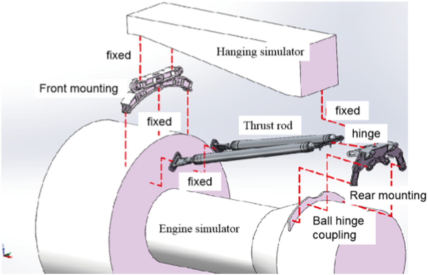
Connection structure
Most of the connection structures between the main parts in the mount shown in Figure 1 are ball hinged couplings. Each ball hinge coupling consists of a binaural piece, a monoaural piece, a set of bolts, a ball and a corresponding ball sleeve, and its structure is shown in Figure 3. In the assembly process, the ball and ball sleeve are concurrently assembled, the monoaural piece and ball sleeve are interference assembly, the pins pass through the entire structure through the ear tabs, balls, and finally lock them with the amphorae by a nut. Ball hinge coupling model.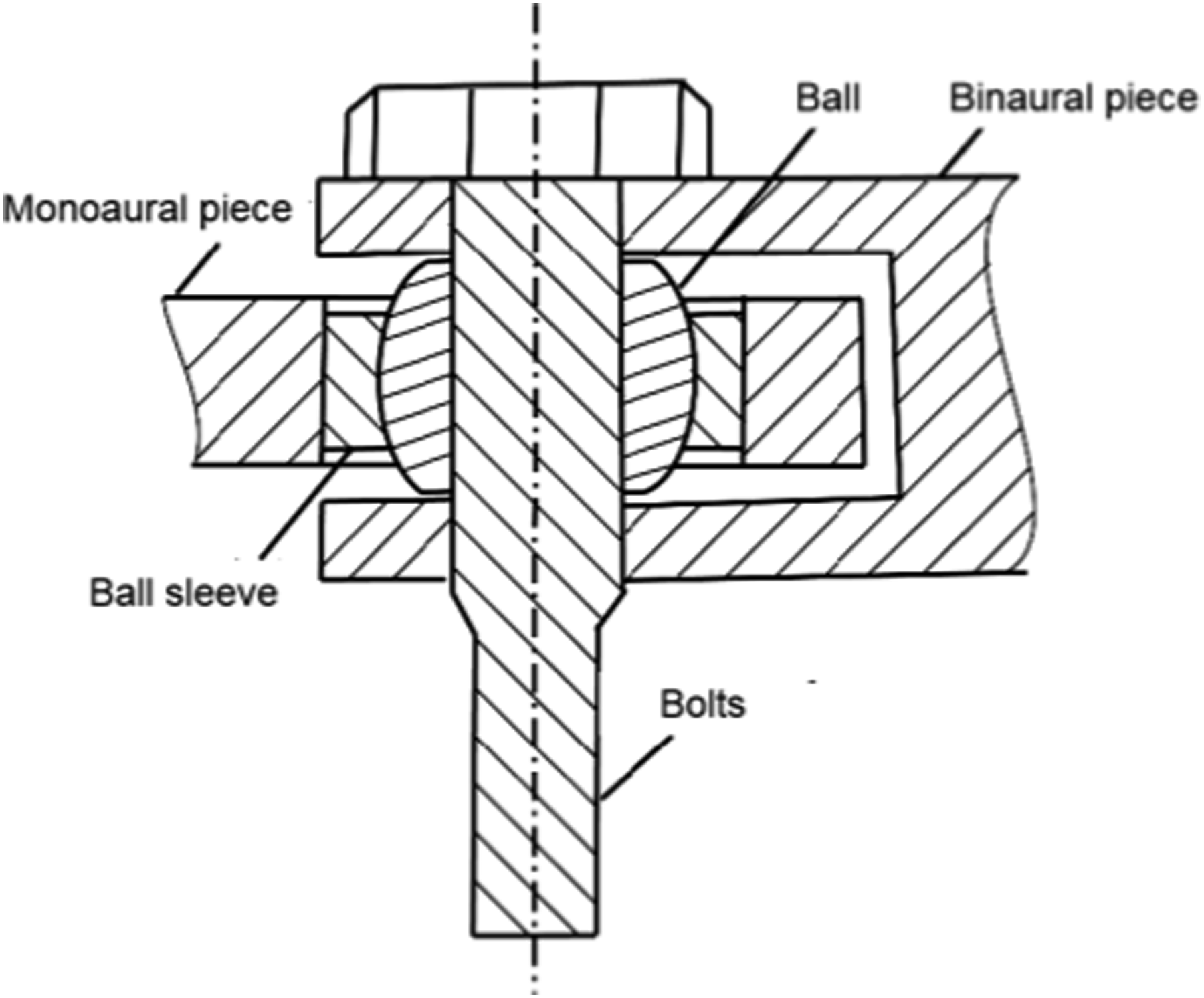
In the multibody dynamics simulation model, the monoaural piece and the ball sleeve are modeled as one body, and each group of ball hinge couplings has a total of four parts: binaural piece, inner ball, ball sleeve and monoaural piece. The constraint relationship of these parts is as follows: the inner ball and the amphora adopt a fixed secondary constraint, the gap contact between the ball and the ball sleeve, and the fixed secondary constraint between the ball sleeve and the monoaural piece, and the entire ball hinge coupling can be regarded as a limit ball hinge with contact stiffness and damping. There are four sets of ball hinge couplings in the front mount of the entire system and 10 ball hinge couplings in the rear mount.
Direction definition
In order to facilitate the description of the six degrees of freedom of the engine, each of these six directions is defined below, as shown in Figure 4. Along the engine axis (i.e., X direction) is defined as heading, horizontal direction (i.e., Y direction) is defined as sideways, vertical direction (i.e., Z direction) defines vertical direction; Rotation around the heading, sideways, and verticals is defined as roll direction, pitch direction, and yaw direction, respectively. Engine coordinate system direction definition.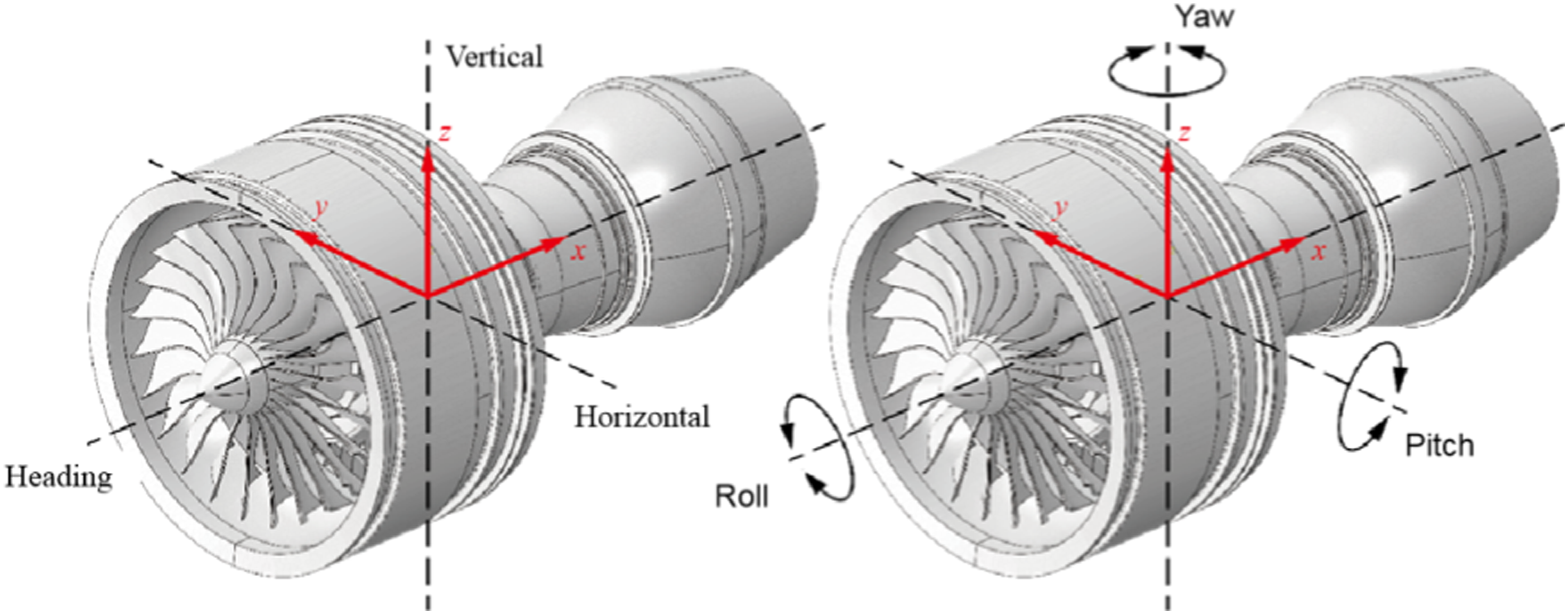
Establishment of the dynamic equation for the mount
Theoretical derivation of kinetic equations
The complete mount system is shown in Figure 1, consisting of a total of eight connecting rods, two fixed hanging joints, one engine body and 14 connecting ball hinges between these parts. In the multibody dynamics modeling process, eight connecting rods are modeled by MNF flexible body, and the generalized coordinates of each MNF flexible body are

The engine body is modeled using a rigid body, and its generalized coordinates are

That is, the number of degrees of freedom is 6.
In addition, the hanging joint is directly connected to the ground and is not modeled separately. The connecting ball hinge modeling calculates the elastic force between the parts without generating additional degrees of freedom, so the total number of degrees of freedom of the system is

The contribution of each element to the system dynamics equation in a multibody model is mainly divided into two parts: the contribution to the mass matrix and the contribution to the rigid body matrix.
The mass array of rigid bodies
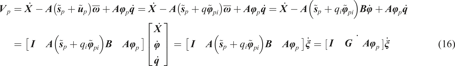
The engine body is modeled using a rigid body, and its generalized coordinates are shown in equation (2), and the coordinates of any point p on it are expressed as

Deriving the coordinates of point p yields the speed of any point p as follows:


Write the speed as a matrix:

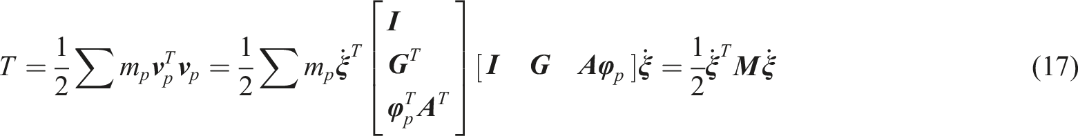
So the kinetic energy of the engine rigid body is expressed as


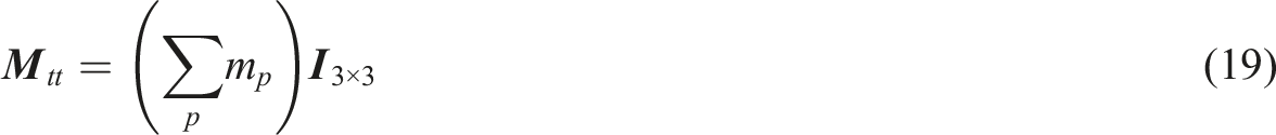
The mass matrix is a symmetry matrix of 6 × 6, corresponding to the 6 degrees of freedom of the rigid body. Since rigid bodies have no elastic potential energy, rigid bodies do not contribute to the stiffness matrix.
Mass array and stiffness array of MNF flexible body
Taking any member as an example, the MNF flexible body model is established, and its degrees of freedom are expressed as

The coordinates of any point p on it are expressed as

Deriving the coordinates of point p yields the speed of any point p as follows:


Write the speed as a matrix:
The kinetic energy of any member is then expressed as
Where the mass matrix is
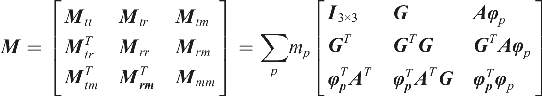
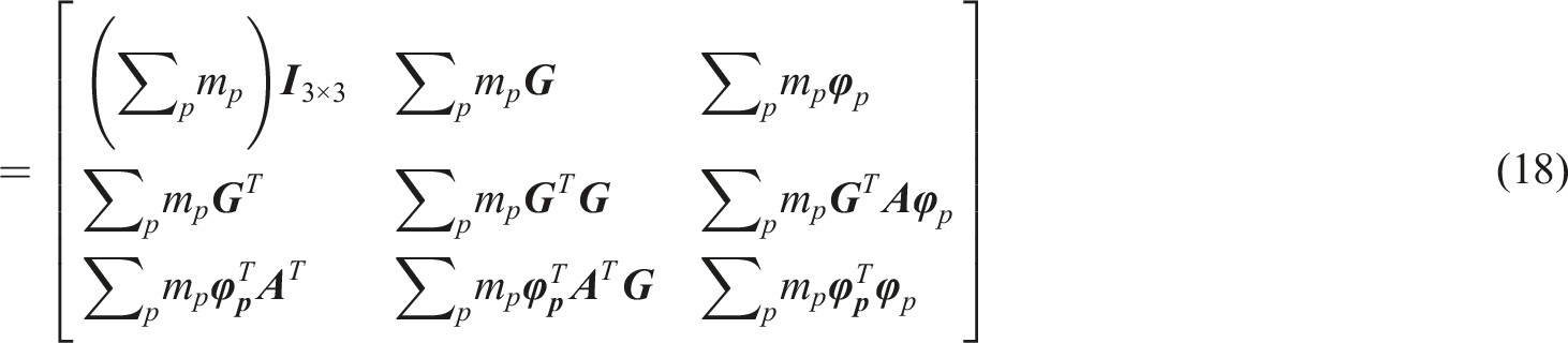
namely,


To simplify the calculation, nine invariants are introduced:


Taking the skew-symmetric matrix for


The mth column (fixed m) of


Bringing the above invariants into the mass matrix yields:


This is the corresponding mass matrix of the MNF flexible body at its (6 + m) generalized coordinates.
For MNF flexible bodies, the elastic potential energy of the system is

The stiffness array of the ball hinge
Taking the connecting ball hinge between two connecting rods modeled by the MNF flexible body as an example, the coordinates of the inner ball center and the ball sleeve center can be expressed as (i is the inner ball parameter, j is the ball sleeve parameter):


The distance offset between the inside ball and the sleeve is

Since the ball hinge has no kinetic energy properties, it does not contribute to the mass matrix. The corresponding elastic potential energy is

So the stiffness array corresponding to the ball hinge is
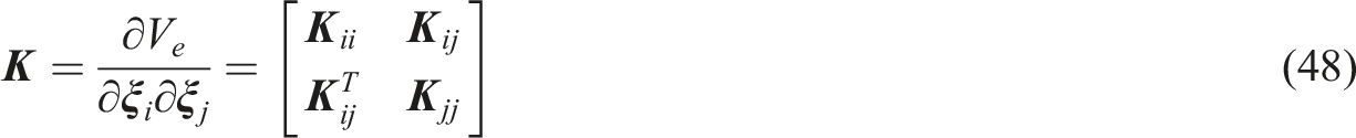
This is the element stiffness matrix corresponding to the ball hinge at the generalized coordinates of (6+m i ) + (6+m j ) at both ends of the connecting rod.
Equation of dynamic equilibrium
When constructing the dynamic equation of the system, take the generalized coordinates of the system:

The generalized coordinates of each of these connecting rod MNF flexible bodies are

The generalized coordinates of the engine rigid body are

Therefore, the total degrees of freedom, that is the generalized coordinate dimension, is

The Lagrange variable is expressed as

Bring in the Lagrange equation
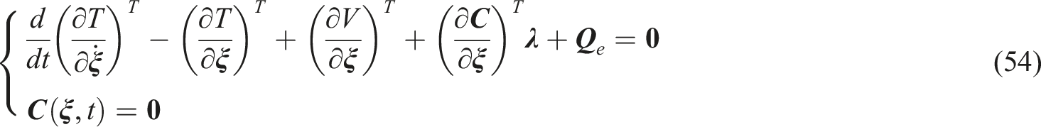
Get

Further simplified to

Substituting equation (56) into equation (55) yields

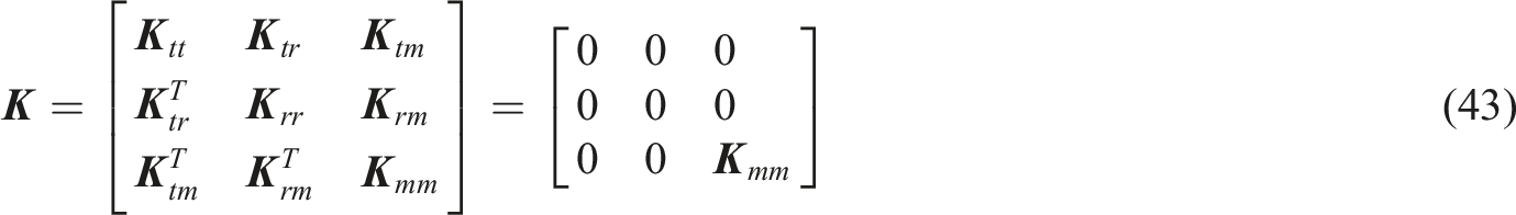
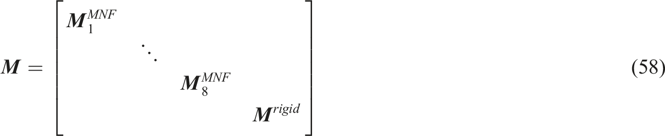
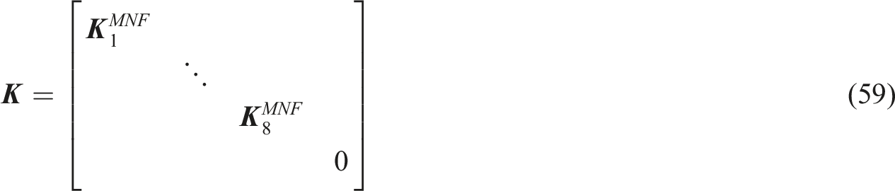
Among them, the overall mass matrix (1) The overall mass matrix is a block diagonal array, and the rigid body and eight MNF flexible bodies assemble their respective element mass arrays into diagonal matrix blocks corresponding to generalized coordinates: The form of the mass array of each block element is described in the previous section, and the ball hinge does not contribute to the mass array. (2)When assembling the overall stiffness matrix, the modal stiffness arrays of the eight MNF flexible bodies are first assembled into the overall stiffness matrix, and the engine rigid bodies do not contribute to the overall stiffness matrix.
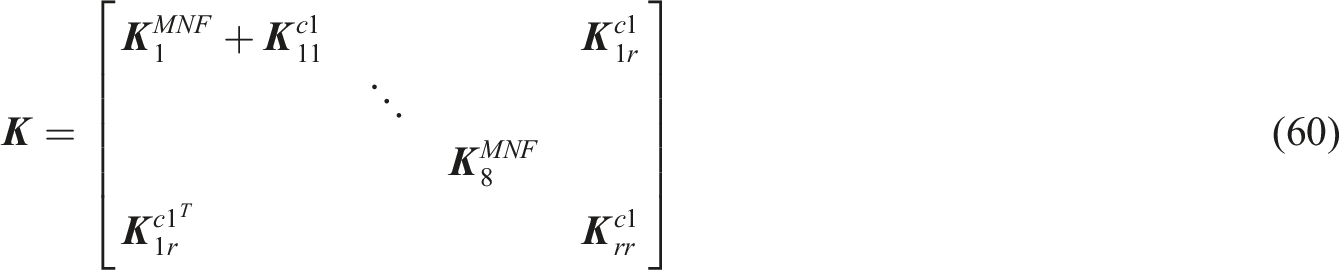
The element stiffness matrix of each ball hinge corresponds to all the generalized coordinates of the two parts, that is, the four matrix blocks in equation (59), such as the ball hinge contribution between the first MNF flexible body connecting rod and the rigid body part:
Low-frequency approximation method for MNF flexible bodies
When the excitation frequency is much lower than the natural frequency of the member, the deformation response of the member to the excitation force can be approximately seen as quasi-static (magnification of about 1), which means that it transmits the force from one member to another member through static deformation over time, as shown in Figure 5. Quasi-static response of low-frequency excitation.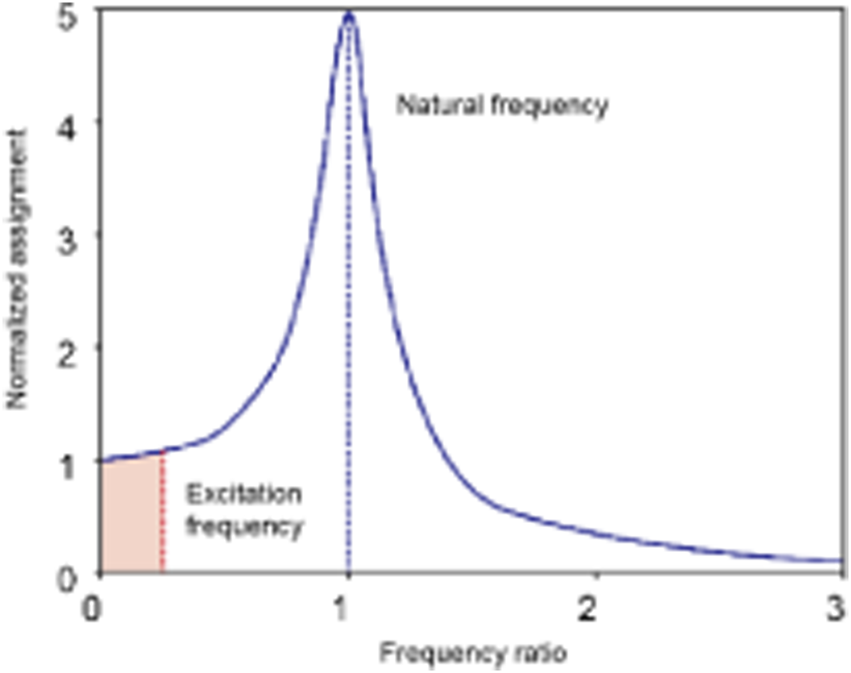
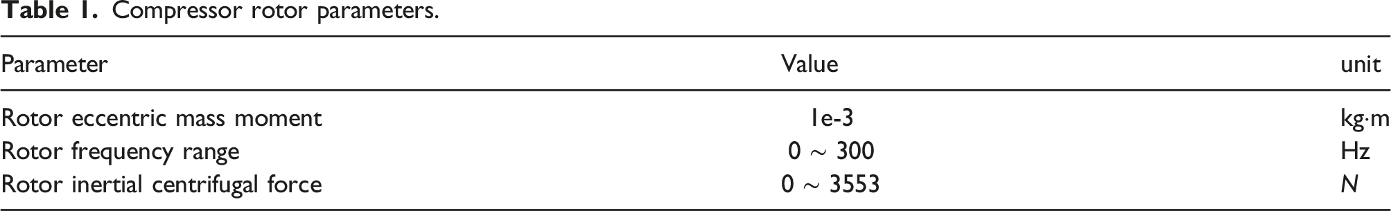
The main excitation force of the mount under actual working conditions comes from the inertia force of the eccentric rotor in the engine. Assuming that the compressor rotor center of mass is point C, the mass is m, and it has an eccentricity e relative to the rotating shaft, when the rotor frequency is f, the inertial centrifugal force on the rotor is magnitude:


Compressor rotor parameters.
Part fundamental frequency versus excitation frequency.
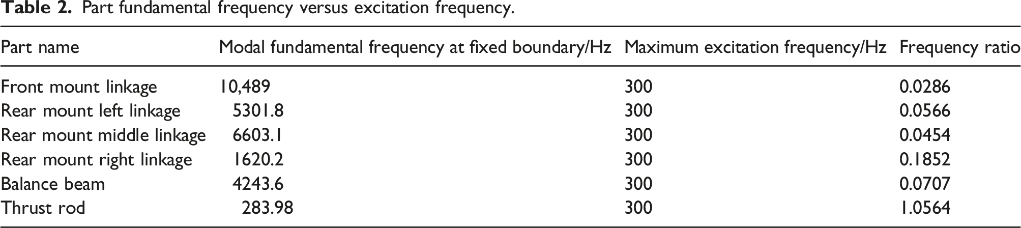
From the results in Table 2, it can be seen that except for the thrust rod parts, the frequency ratio of the highest excitation frequency of the rotor and the fundamental frequency of the part is less than 0.2, that is, the excitation frequency is in the shadowed region in Figure 5, and the response of the rotor excitation to each part can be regarded as a quasi-static response, which is the prerequisite for the application of the low-frequency approximation method.
Introduction to low-frequency approximation methods
In the rigid-flex coupling mounting model studied in this paper, the flexible members are modeled using MNF flexible bodies. Taking one of the MNF flexible bodies as an example, and its dynamic equation is established by the first type of Lagrange equation: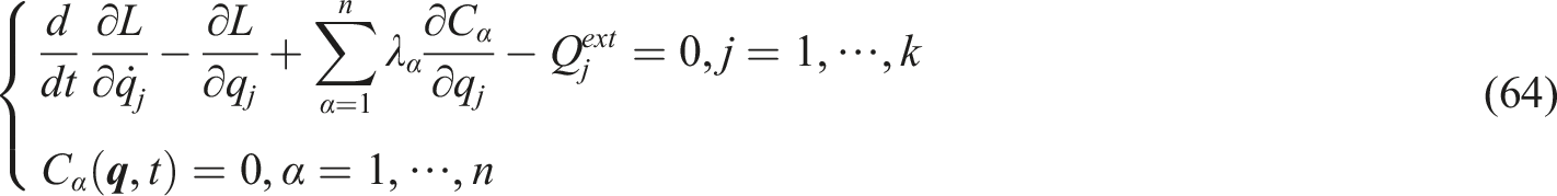
After simplifying equation (20), we get
Based on the traditional Craig-Bampton method, it divides the system degrees of freedom into two parts: boundary degrees of freedom (or interface degrees of freedom)
The relationship between the physical and modal coordinates of a system can be expressed as
Since the frequency of external excitation in the mounting system is much lower than the natural frequency of the member, the overall degree of freedom of the member can be reduced by ignoring the contribution of the main mode of the fixed interface. The degrees of freedom of the member can be reduced from
The relationship between physical and modal coordinates can be simplified to
Low-frequency approximation modal neutral file flexible body verification
Static response result
Comparison of static response results of different fixed interface master modes.
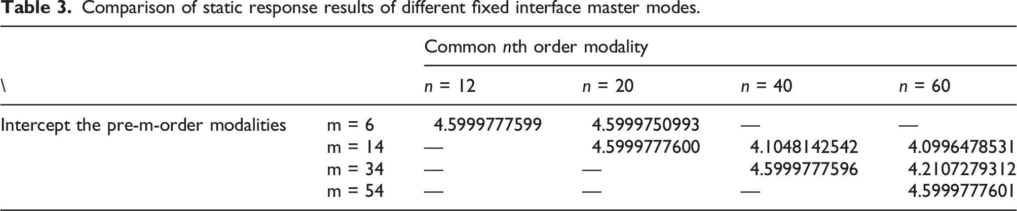
As can be seen from Table 3, the static response results of the MNF flexible body can only obtain accurate results when all the master modes are selected. This is because after modal orthogonalization, all principal modes contain boundary-static constrained modes, and the modal information of each order must be combined to obtain accurate results.
Periodic excitation response results
The periodic excitation response results of MNF modal flexible bodies after reducing the main mode of the fixed interface are verified. As an example of the MNF flexible body of the front mount linkage, the linkage is fixed at one end, and the excitation load F
ex
= 105sin (2πft) N in the tensile direction is applied at one end, and the difference in the displacement results of the tensile end when comparing different modal orders is shown in Figure 6. Comparison of dynamic responses corresponding to different excitation frequencies:(a) f = 1000 Hz (Much below the 12th order modal fundamental frequency);(b) f = 10,000 Hz (Approaching the highest frequency of the 12th order modality);(c) f = 20,000 Hz (Approaching the highest frequency of the 20th order modality).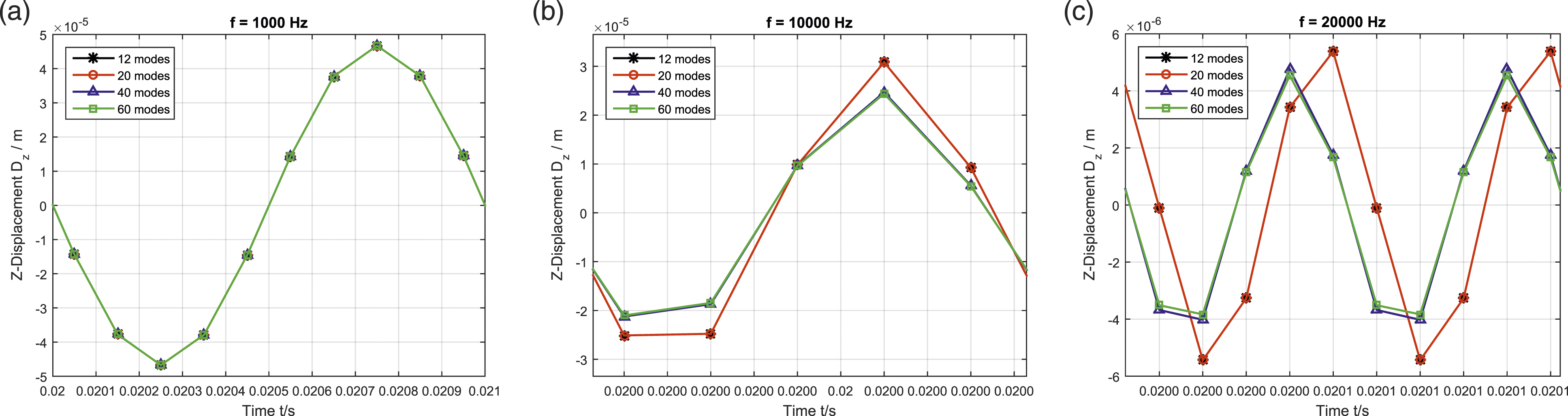
It can be seen from Figure 6 that when the excitation frequency is much lower than the natural frequency of the member, few fixed interface main modes can obtain accurate excitation response results, and when the excitation frequency is close to the low-order frequency of the member, more main modes must be selected to accurately calculate the dynamic response results of the member, which shows that the approximation method under low-frequency excitation is feasible.
Figure 7 shows the distribution of modal frequencies of each order when the MNF flexible body model selects different modal orders, and it can be seen that the more total modal orders selected by the MNF flexible body, the more accurate the corresponding low-order frequency (less than 10,000 Hz), which explains the large deviation of the results of selecting a small number of modal MNF flexible bodies when the frequency of external excitation is close to this frequency. From the frequency results in the Figure 7, it can be determined that when the highest modal frequency of the MNF flexible body is more than 4 times the excitation frequency, the excitation response of the frequency is accurate, that is, when the excitation frequency is less than 1/4 of the fundamental frequency of the flexible body, all the dynamic modes of the flexible body can be ignored. The frequency of the member corresponding to the number of main modes of the different fixed interfaces.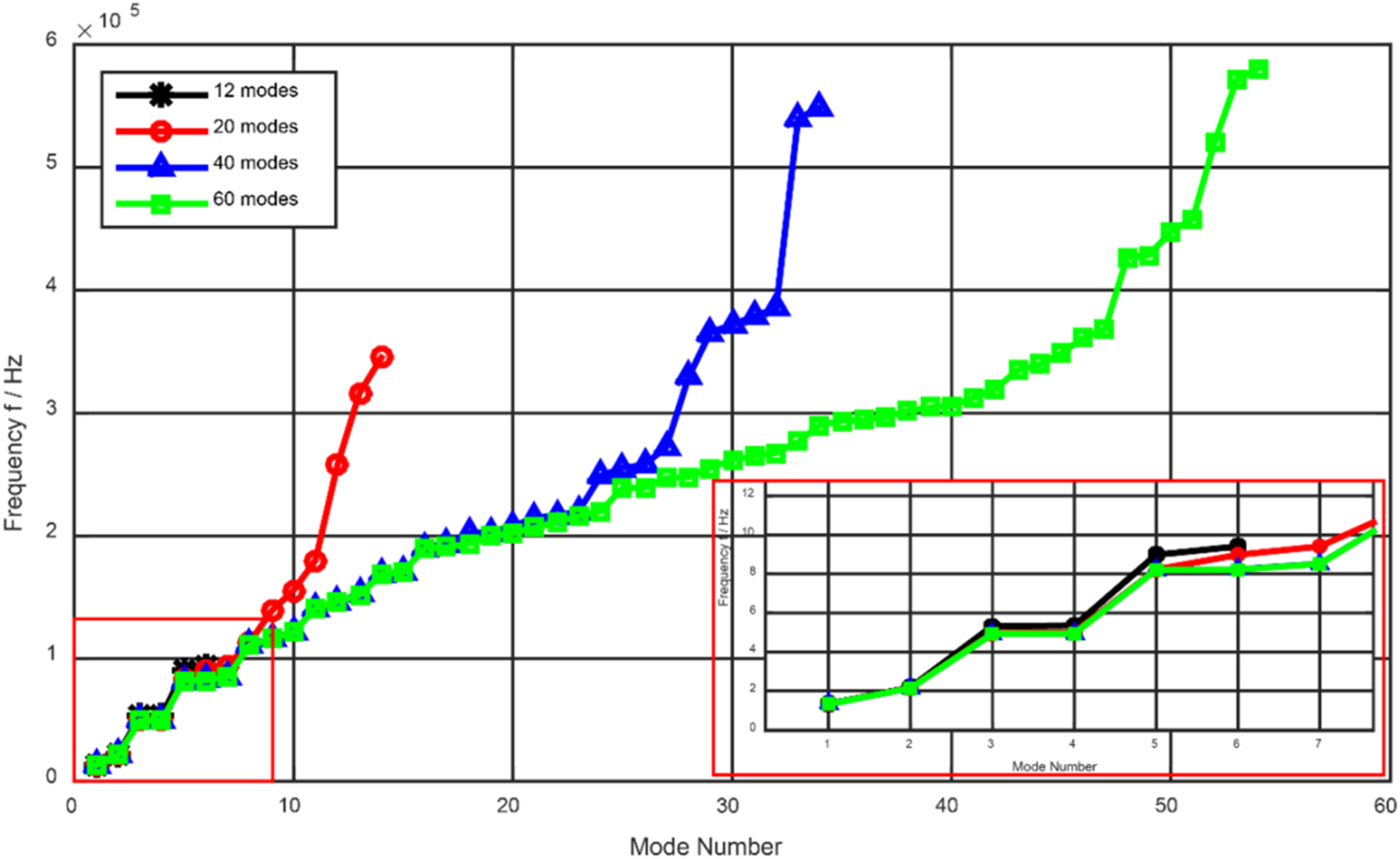
Simulation example
Vibration isolation performance evaluation index of engine mount
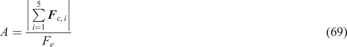
In order to evaluate the vibration isolation effect of the engine mount, the transmittance at each connection point in the mount system is defined as

By modeling and analyzing the mount system, the time domain response of the force on each ball hinge under the unbalanced excitation can be obtained. The force of the ball hinge at the upper end of the left, middle, and right connecting rod of the front mount and the left, middle, and right connecting rod of the rear mount is vector-summed to obtain the time domain response of the force experienced by the hanging joint. In order to further obtain the transmittance of the system, the time domain response of the resultant force on the suspension is FFT transformed, and the first order response amplitude of which the transformed frequency is the same as the excitation frequency is taken as the vibration amplitude of the system after stabilization.
Frequency domain response results and analysis
Based on the theoretical analysis of Section “Establishment of the dynamic equation for the mount”, the established dynamic model of rigid-flex coupling is shown in Figure 8. Dynamics model of the engine mount.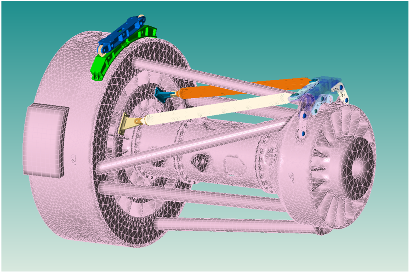
Comparison of the response of low-frequency approximate MNF flexible member and full MNF flexible member
Apply a heading thrust of 23 kN and a gravity of −35 kN to the mount, and apply lateral and vertical sweep excitation loads at the center of gravity of the engine as shown in equations (62) and (63). Measure the transmittance of the four ball hinges of the front mount, as shown in Figure 9. Comparison of transmittance curves of low-frequency approximation MNF flexible body and complete MNF flexible body: (a) front-up-left ball hinge; (b) front-up-right ball hinge; (c) front-down-left ball hinge; (d) front-down-right ball hinge.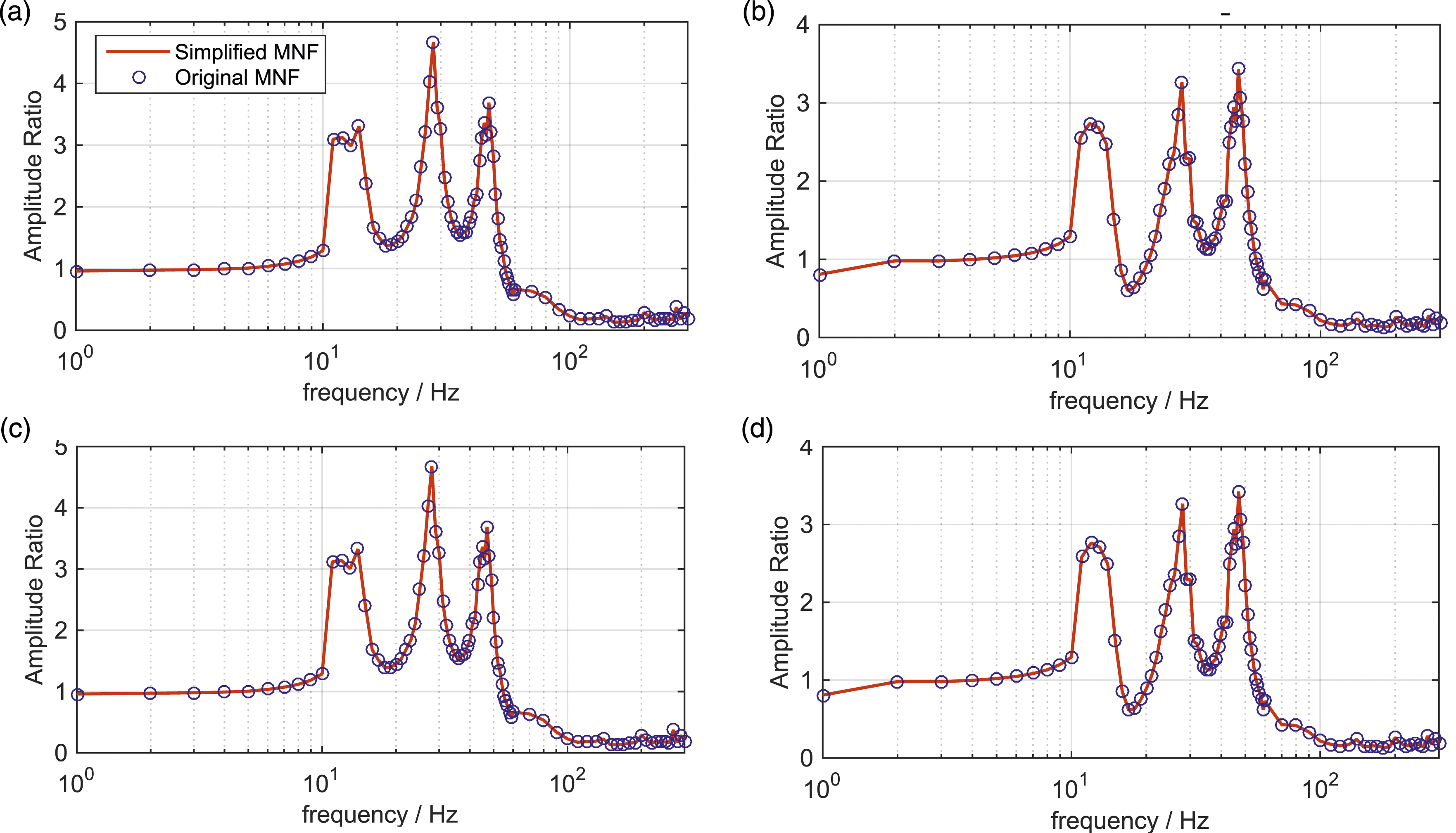
It can be seen that when the excitation condition of the engine mount meets the requirements of the low-frequency approximation method, the rigid-flex coupling model established by the low-frequency approximation method can accurately obtain the dynamic response of the system. Meanwhile, compared with the complete MNF flexible body model, it can reduce the system freedom by more than 2/3, which greatly improves the calculation efficiency.
Vibration isolation efficiency at rotor frequency
Vibration isolation efficiency at low pressure rotor frequency
A heading thrust of 23 kN and a gravity of −35 kN were applied to the mounting system, and fixed frequency excitation at 59 Hz was applied at the low-pressure rotor according to equations (62) and (63), with an excitation amplitude of 1000 N.
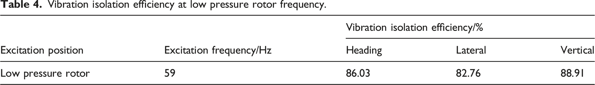
The time domain response of the forces applied to the hanging joint is shown in Figure 10, which by vector sum the forces on the left and right connecting rods of the front mounting section and the ball hinge at the upper end of the left, middle and right connecting rods of the rear mounting section. After FFT according to equations (68) ∼ (70), the three-way vibration isolation efficiency of the mounting section at the low-pressure rotor frequency is shown in Table 4. Three-way response time domain curve under engine mounting low-pressure rotor excitation. Vibration isolation efficiency at low pressure rotor frequency.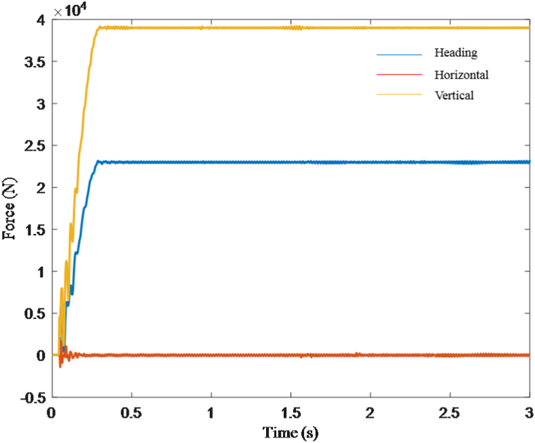
Vibration isolation efficiency at high pressure rotor frequency
A heading thrust of 23 kN and a gravity of −35 kN were applied to the mounting system, and fixed frequency excitation at 248.5 Hz was applied at the high-pressure rotor according to equations (62) and (63), with an excitation amplitude of 1000N.
The time domain response of the forces applied to the hanging joint is shown in Figure 11, which by vector sum the forces on the left and right connecting rods of the front mounting section and the ball hinge at the upper end of the left, middle and right connecting rods of the rear mounting section. After FFT according to equation (68) ∼ (70), the three-way vibration isolation efficiency of the mounting section at the high-pressure rotor frequency is shown in Table 5. Three-way response time domain curve under engine mounting low-pressure curve under engine mounting high-pressure rotor excitation. Vibration isolation efficiency at high pressure rotor frequency.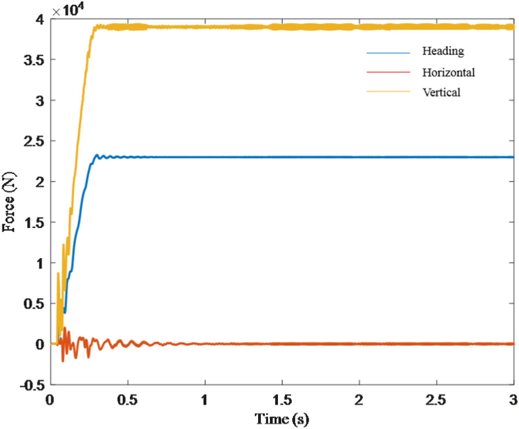

Experimental validation
Test platform
In order to obtain the vibration isolation efficiency at the high and low rotor frequencies of a certain engine mount as shown in Figure 1, and verify the accuracy of the rigid-flexible coupling dynamics model of the engine mount established above, this paper built a verification platform for the vibration reduction and isolation performance of the full-size engine mount (as shown in Figure 12) based on the four-terminal parameter method for the mount as shown in Figure 1, and carried out experimental research. The platform is mainly composed of test base frame, fixed boundary simulator, three-way force sensor, mounting section, engine simulator (rotary excitation tester) and so on. Among them, the three-way force sensor is the standard product. Full-size engine mounting system vibration isolation performance test platform.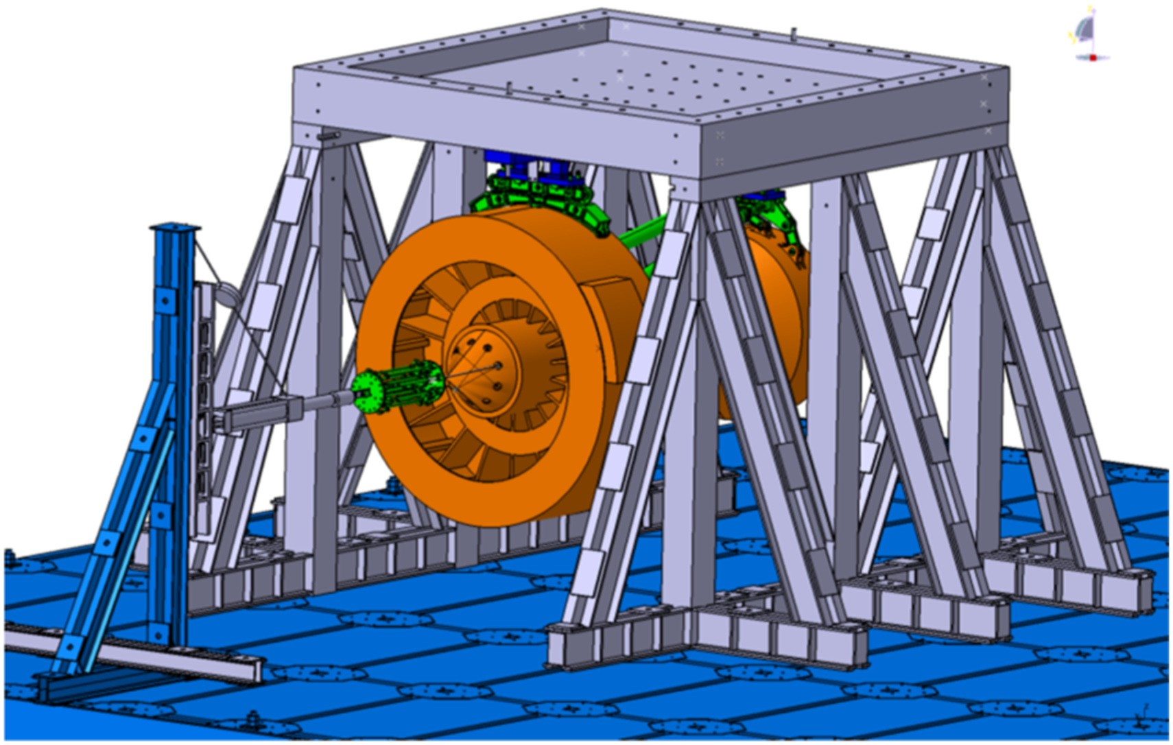
Loading
The load spectrum.
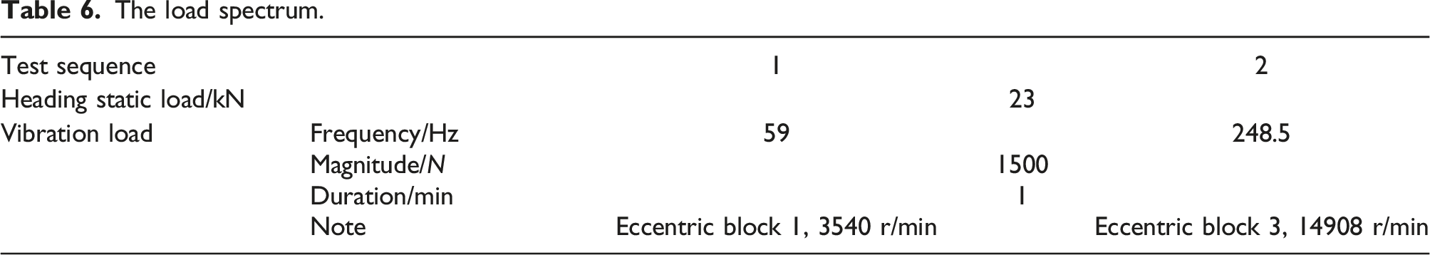
As the transitional loading device of vibration load and thrust load, the engine simulator should be consistent with the inertia parameters (mass, center of mass, moment of inertia, etc.) and interface size of the engine model under test.
The engine simulation part designed in this paper is shown in Figure 13, which is mainly composed of the outer shell of the fake part, the rotating shaft, the supporting disk of the rotating shaft, the eccentric block, the drive motor, the control system, etc. It can not only meet the above basic requirements, but also simulate the basic characteristics of the engine rotational unbalance vibration. Instead of the traditional exciter/shaker excitation method, it can eliminate the influence of the additional stiffness of the boundary, and provide vibration load input for the vibration transmission test of the engine installation system. The maximum driving speed can reach 20,000r/min, and the eccentric block 1 is located at the front support of the tester rotating shaft, the eccentric block 2 is located at the heavy center of the tester, and the eccentric block 3 is located at the support of the tester rotating shaft, which can realize the stepless adjustment of the exciting force of 0N–5000 N. Engine simulator - rotary excitation tester.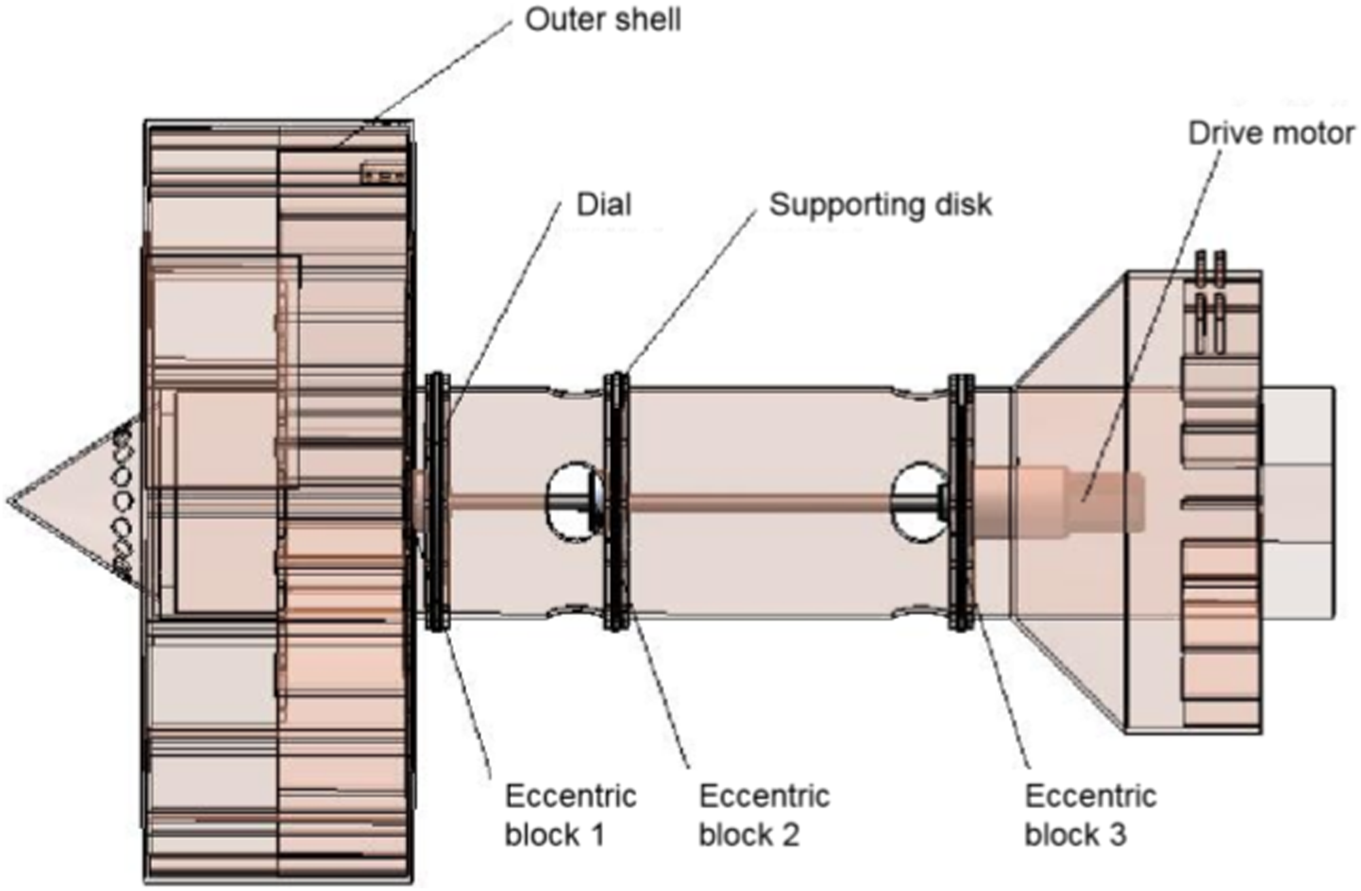
Measuring
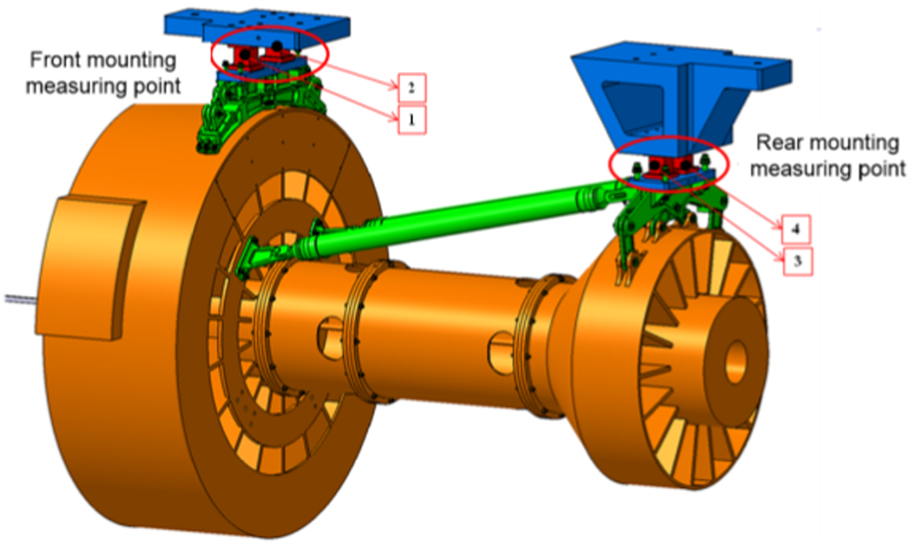
The test measurement is shown in Figure 14, which is mainly composed of a three-way force sensor, a data acquisition system, and a built-in force sensor in the engine simulator. Among them, the three-way force sensor is used to measure the test of point force response, and the distribution is shown in Figure 15, in which 2 three-way force transducers are arranged at the front mounting section and 2 three-way force sensors are arranged at the rear mounting section. The built-in pressure sensors are used for the test of excitation loads and are located near the three eccentric blocks. Schematic diagram of the measurement system. Load measurement point.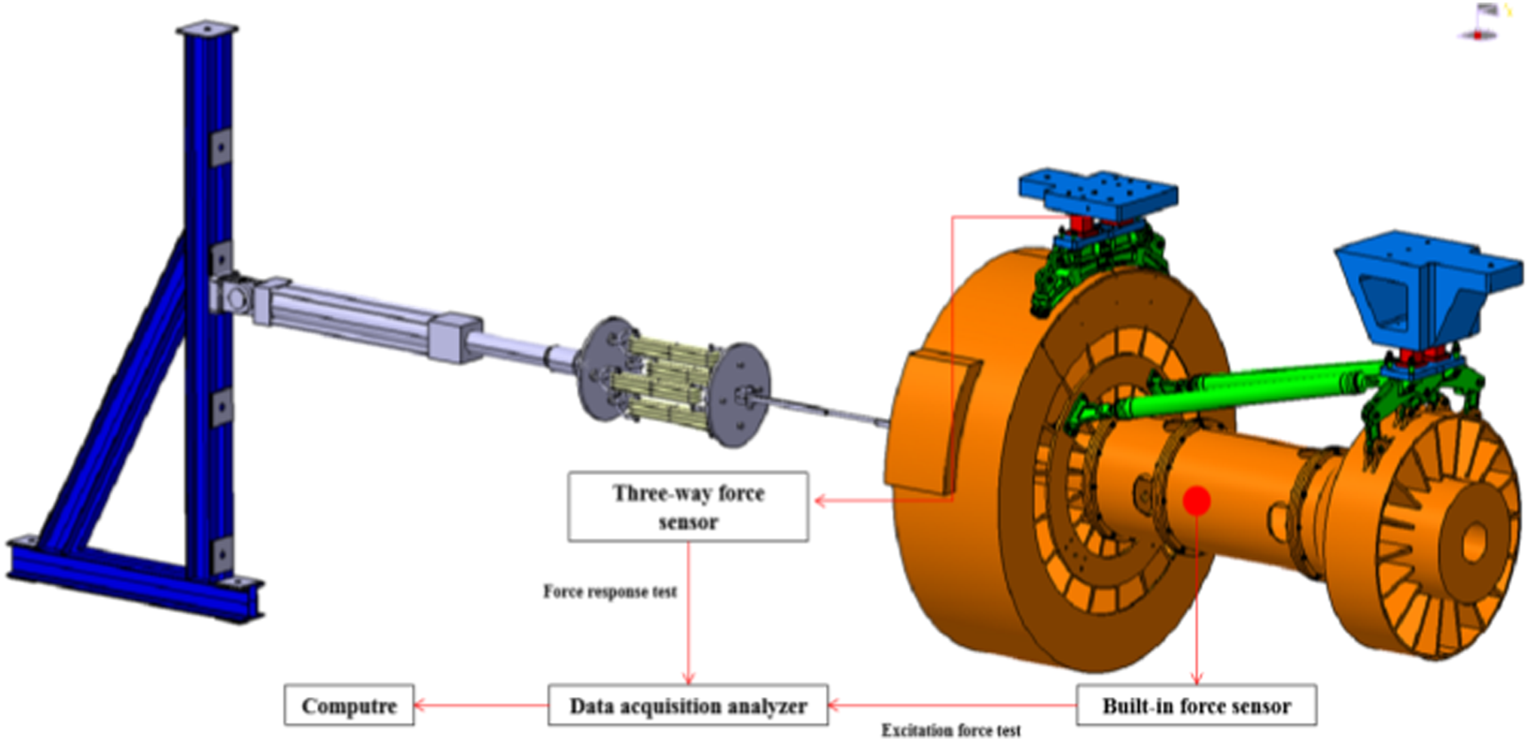
Analysis and comparison of results
The test site is shown in Figure 16. Test site: (a) Test site; (b) low pressure rotor eccentric block;(c) low pressure rotor eccentric block control interface;(d) high pressure rotor eccentric block;(e) high pressure rotor eccentric block control interface.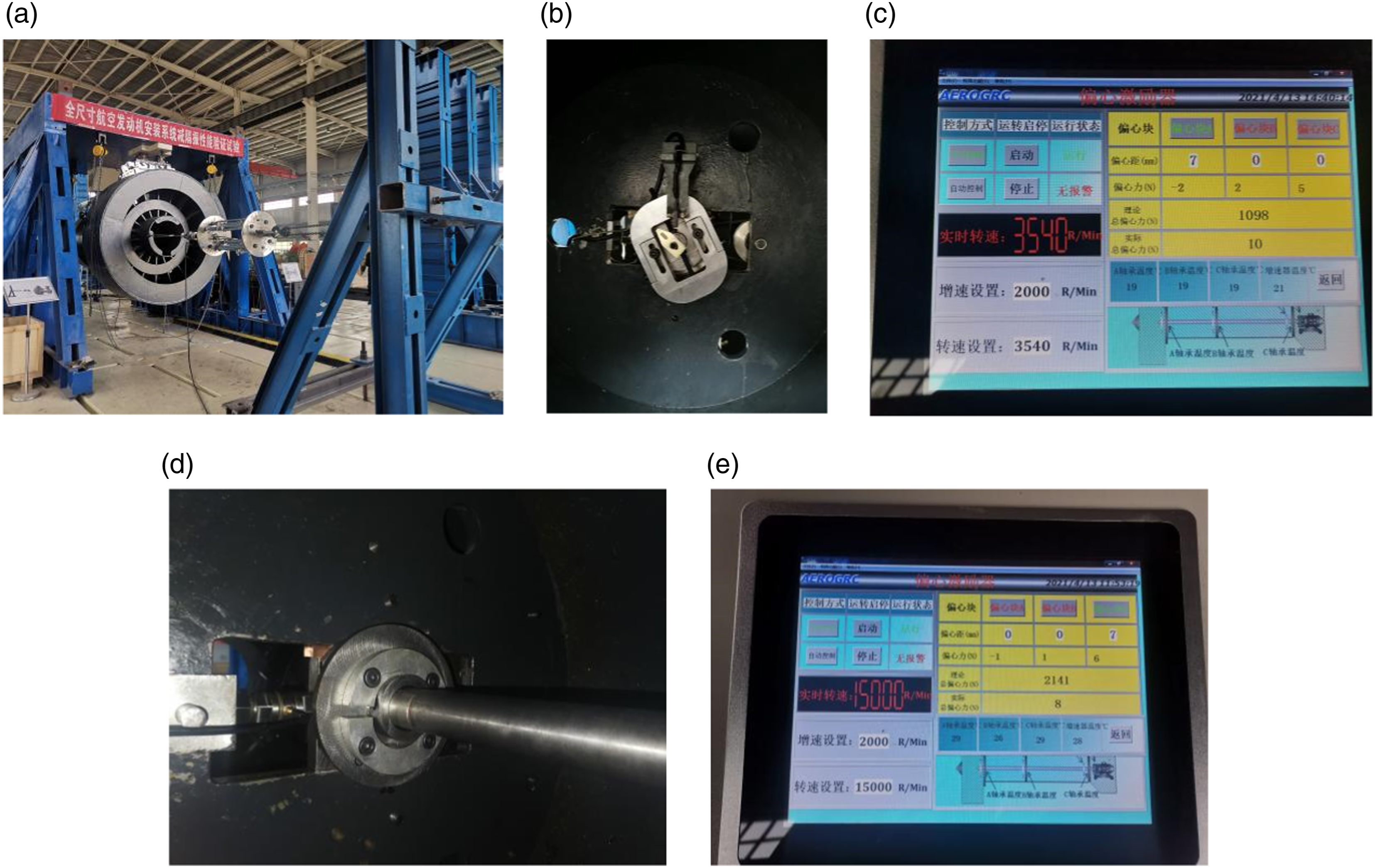
At the low pressure rotor frequency, the excitation versus response time domain curves are shown in Figure 17(a). The amplitude curve is calculated by FFT method as shown in Figure 17(b), where XX represents the lateral response, YY represents the heading response, ZZ represents the vertical response, and ABC represents the excitation data. Response at low pressure rotor frequency: (a) time domain; (b) frequency domain.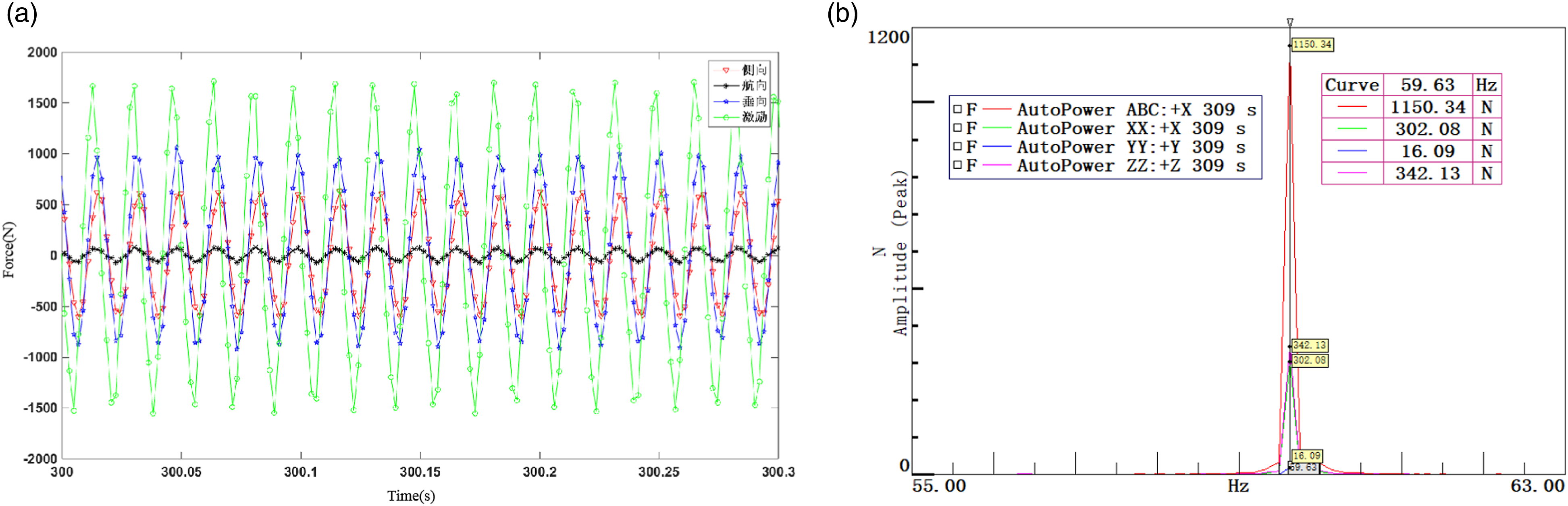
At the high pressure rotor frequency, the excitation versus response time domain curves are shown in Figure 18(a). The amplitude curve is calculated by FFT method as shown in Figure 18(b), where XX represents the lateral response, YY represents the heading response, ZZ represents the vertical response, and ABC represents the excitation data. Response at high pressure rotor frequency: (a) time domain; (b) frequency domain.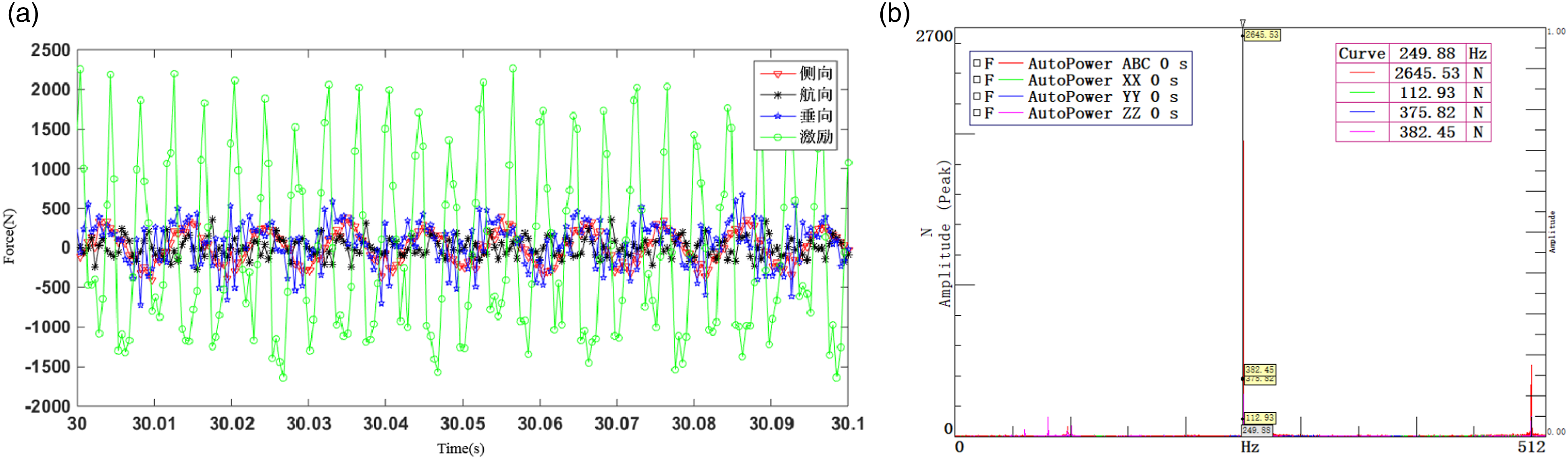
Comparison of simulation and test results.
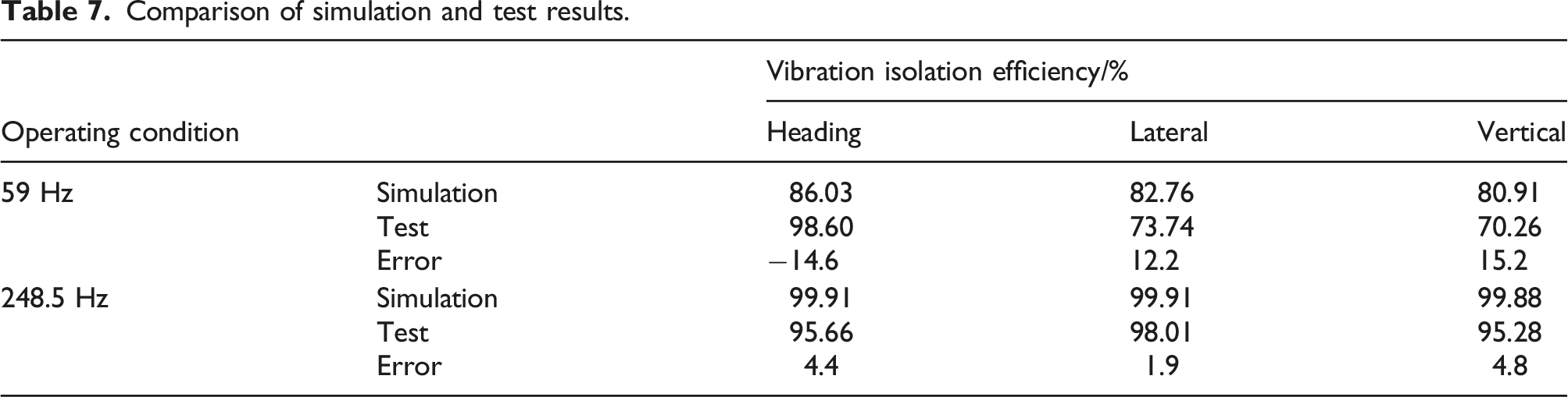
In order to improve the accuracy of calculations and experiments at low rotor frequencies, the relevant causes were further analyzed: (1) During the simulation analysis, due to the complexity of the internal structure of the engine simulation component as a rotating excitation tester, in order to improve the computational efficiency while ensuring a certain level of accuracy, the engine simulation component in the simulation model was rigidized. However, the real engine simulation component cannot be completely rigid, resulting in differences between the test results and the analysis results. (2) During the test, a set of three-dimensional force sensors with high stiffness was installed between the end of the installation segment and the fixed boundary to obtain the vibration response transmitted to the end of the installation segment. However, during the analysis, the end of the installation segment was generally constrained directly, resulting in differences between the test boundary and the simulation boundary, which in turn led to differences between the test results and the analysis results. (3) Further research will be conducted based on real engines and real wings or wing simulation devices.
Conclusion
By using multibody dynamics method, this paper establishes the kinetic theoretical equation for the engine of a turbofan engine, and proposes a low-frequency approximation method for MNF files, which greatly improves the calculation speed on the basis of ensuring the calculation accuracy. At the same time, a full-scale engine mount vibration reduction performance test platform was developed, and the vibration isolation efficiency of a certain engine mount at the high and low pressure rotor frequency was obtained. The results show that the simulation and the test results are very close, and the error at the frequency of the low-pressure rotor is within 15%. At the high-pressure rotor frequency, the error is within 5%. The accuracy of the established rigid-flex coupling model and test is further verified. The dynamic modeling method of rigid-flex coupling of engine mount proposed in this paper and the vibration reduction and isolation performance test platform of full-scale engine mount can provide analysis means and test basis for the localization of engine mount of large passenger aircraft in China.
Footnotes
Declaration of conflicting interests
The authors declare no potential conflicts of interest with respect to the research, authorship, and/or publication of this article.
Funding
The author(s) received no financial support for the research, authorship, and/or publication of this article.