
Abstract
The dynamic performance of three slab ballastless tracks in the China Railway Track System (CRTS), which is supported by a simply supported box girder under various train loads, were comprehensively investigated with refined rigid-flexible coupled models. A refined rigid-flexible coupled model of vehicle-multi layer track-bridge system was developed to investigate the dynamic performance of three various CRTS slab tracks (i.e., CRTS I, II, III) under various conditions of train models, speeds and loads, respectively. The numerical analysis was conducted by using the combination of ANSYS and Universal Mechanism. It shows that the developed refined model has the capability of simulating the vehicle-slab track-bridge interaction with consideration multi-layer track structures, and the model predictions agree reasonably well with the experimentally measured wheel load reduction rate, lateral displacement and lateral acceleration of the bridge under different train speeds. The parameters of derailment system, vertical and lateral acceleration, the wheel-rail contact force, and Sperling index gradually become larger with the increase of the train speed, especially when the speed increases to 350 km/h. In addition, there is a significant increase in vertical wheel-rail contact force while a decrease in Sperling index when the train with full load capacity. Furthermore, the CRTS III slab track has demonstrated a better dynamic performance of track and bridge structures in comparison to CRTS I and CRTS II slab ballastless tracks.
Keywords
Introduction
The ballastless tracks have been developed worldwide in the recent decades due to their advantages of environmental friendliness, stability in both longitudinal and lateral directions, and lower maintenance.1–3 Currently, there are three common types of slab ballastless track structures in China Railway Track System (CRTS) (i.e., CRTS I, CRTS II and CRTS III). The slab ballastless track structure of CRTS I–III consists of three layers (i.e., rail, fastener, track slab, supporting layer, and base plate). The training speed on slab tracks is planned to increase from 350 km/h to 400 km/h in recent years and the train weight is planned to increase to 30,000 tons in near future. Thus, the dynamic performance of the vehicle-slab track-bridge coupling system under the high-speed and weight needs to be further investigated to ensure the safety of the high-speed trains.
There are four main train models of high-speed trains currently operating in China (i.e., CRH2, CRH3, CRH5, and CRH380). The design speed of CRH2 and CRH5 is 200 km/h level with a maximum speed of 250 km/h, while the design speed of the CRH3 and CRH380 is 350 km/h with a maximum speed of 380 km/h. 4 The coupled vehicle-track-bridge dynamic characteristics have been intensively investigated in recent years, most of which mainly focuses on the dynamic behavior of the coupled system under normal train weight and a train speed ranging from 250 to 350 km/h;5–7 the dynamic characteristics of the system under a relatively higher train speed and weight require further research work. Zhai and Chen studied the effects of the ground vibrations on a ballastless track and compared the variety of dynamic response under various high speeds, 8 their results proved the vehicle-track-bridge dynamic interaction and proposed the safety threshold. Qu established the three-dimension spatial coupled model to identify the key factors that affect the mechanical behavior of the coupled CRTS I track-bridge structure, 9 and found that resistance fastenings decrease the maximum additional longitudinal rail force and track structure stress. In addition, Zhou established the three-dimension finite element model of the CRTS II track-bridge structural system to explore the deformation of the system, 10 and indicated that the theory of model is proved by experiment. Furthermore, Liu established the two-dimensional vehicle-track-bridge coupling model and dynamic compliance method to analyze the dynamic responses of the CRTS III track and bridge structure. 11 Their results showed that the CRTS-III damping track system can mitigate the viaduct average acceleration with 60.4%. However, the dynamic performance of different slab tracks in vehicle-track-bridge system under high-speed train is unclear, especially for the 400 km/h and the train operation with full load capacity.
It has been shown that the rigid-flexible coupling method is one of suitable numerical methods for simulating the dynamic behavior.12,13 Dietz studied the vehicle-track-bridge interaction under different train speeds using rigid-flexible coupling method, 14 while Shi used the dynamic theory of flexible multi-body system to evaluate the stability of the vehicle-track-bridge system under daily train loading.15,16 Their results show that the theory could improve the vibration performance by increasing the firing accuracy. In addition, the study of Niu showed that there is a relationship between train load and stiffness. 17 Using an improved three-dimensional finite element (FE) bridge model and a 15 degrees-of-freedom (DOF) train model, Gou studied the effect of the train speed on dynamic performance of the train and found that the bridge resonance is influenced by the train. 18 Other numerical methods were also developed for modeling the dynamic characteristics of a moving load.19,20 Further, the study of Wu indicated that Universal Mechanism (UM) is suitable for modeling the rigid-flexible coupling problems. 21 However, the multi-layer track structures as a single element in the vehicle-track-bridge system without consideration of the interaction between these layers of track were simplified in previous studies, which could lead to the deviation of dynamic performance for track structure.
Therefore, this paper investigates the dynamic performance of multi-layer slab tracks in vehicle-track-bridge system under different train loads and speeds. Firstly, the multi-body dynamic theory was introduced to simulate the vehicle-track-bridge interaction. The refined rigid-flexible coupling model of considering multi-layer different slab track structures were then developed and numerically solved using commercial ANSYS and UM software. Secondly, the dynamic responses of the trains in refined vehicle-CRTS II slab track-bridge system under various train models, speeds, and loads were compared, respectively. Finally, the dynamic performance of refined CRTS I, CRTS II, and CRTS III slab track-bridge structures under high-speed of 350 km/h was analyzed. This study could be helpful to comprehensively understand the interaction and operation risk of the vehicle-track-bridge system.
Rigid-flexible coupling models of vehicle-track-bridge system
Refined rigid-flexible coupling model in vehicle-track-bridge system
The dynamic responses of the vehicle-slab track-bridge system under various train loads are simulated, in which three types of China Railway Track System (i.e., CRTS I, II, and III slab ballastless tracks) are selected. Based on the multi-body theory, Figure 1 illustrates the flow chart of the refined rigid-flexible coupling model of a vehicle-slab tracks-bridge system, where the different vertical components of the train models and three slab track structures are considered to compare the dynamic responses of vehicle-slab tracks-bridge system under various train loads, respectively. It should be noted that the bushing connection is used for the interaction of different layers in track structures, and CAM and SCC are the abbreviations of cement asphalt mortar and self-compacting concrete, respectively. There are four performance measures of the vehicle-track-bridge system used in this study. The details of these four performance measures can be expressed as: Flowchart of the refined rigid-flexible coupling model in vehicle-track-bridge system.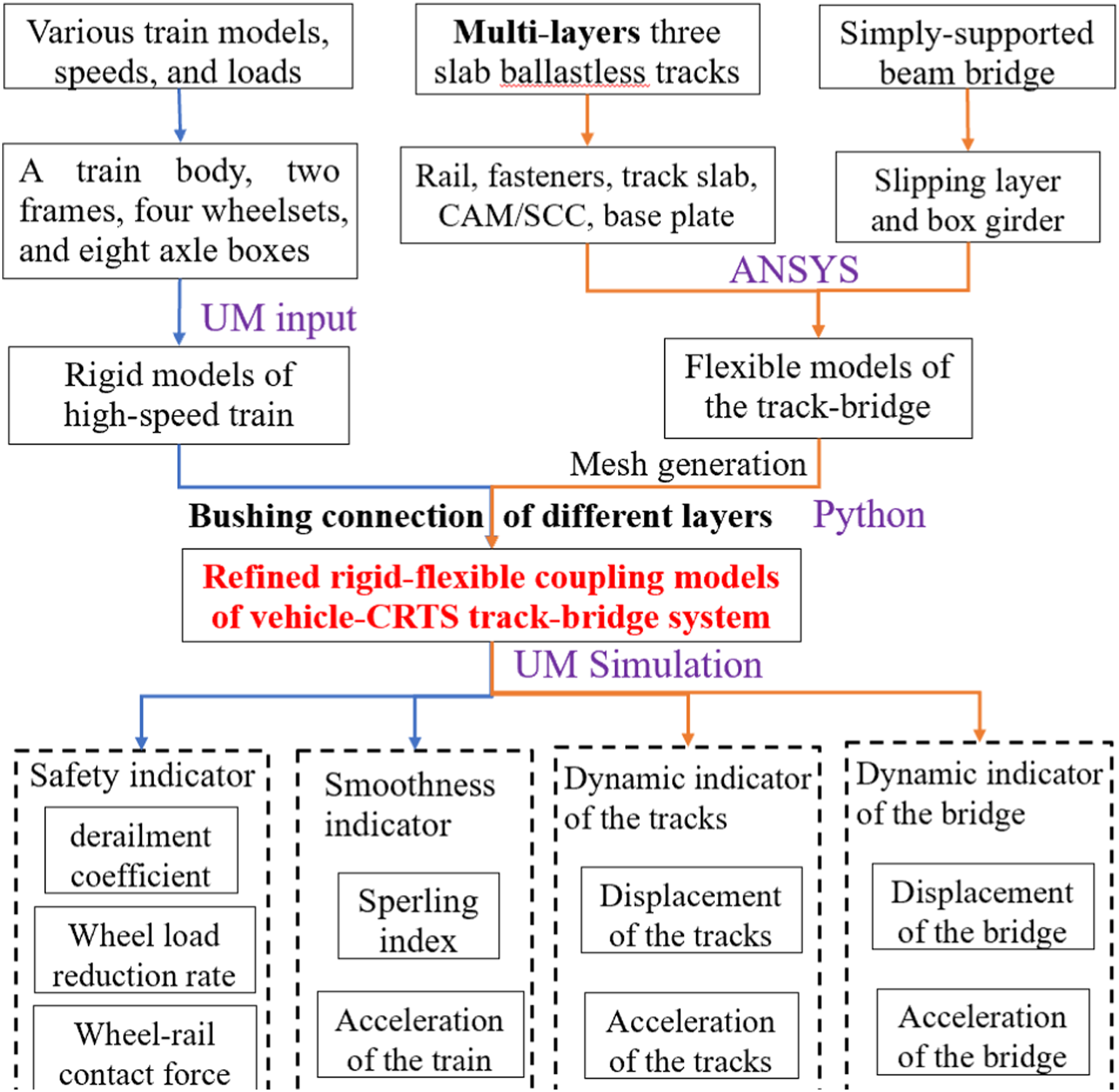
Safety indicator is represented by derailment coefficient, wheel load reduction rate, and wheel-rail contact force
• Derailment coefficient: the ratio of the lateral force and vertical force on the wheel • Wheel load reduction rate: the ratio of the wheel weight of the load reduction side to the average static wheel weight • Wheel-rail contact force (H):
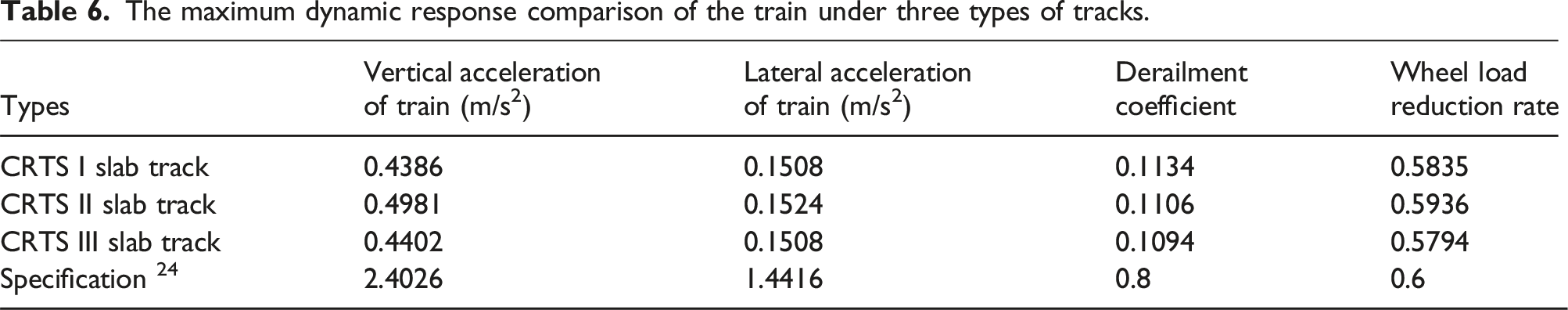
The allowable range of derailment coefficient and wheel load reduction rate is 0.8 and 0.6, respectively. 22
Smoothness indicator is represented by Sperling index and acceleration of the train
• Sperling index (W) • Acceleration of the train

The allowable lateral and vertical acceleration of the train (when the train speed belongs 300∼ 350 km/h) is 0.6 and 1.0 m/s2 (TB 10761-2013).
Dynamic indicator of the tracks represented by displacement and acceleration of the tracks
• Displacement of the tracks • Acceleration of the tracks
The allowable range of lateral displacement is 0.5 mm, and allowable range of vertical displacement is 0.4 mm. The acceleration of the tracks limits to 300 m/s2 (TB 10761-2013).
Dynamic indicator of the bridge
• Displacement of the bridge • Acceleration of the bridge
The allowable range of lateral displacement and acceleration is L/4000 (when the train speed is 350 km/h) and 1.4 m/s2. The allowable range of vertical displacement and acceleration is L/1600 (when the train speed is 350 km/h) and 5 m/s2. 22
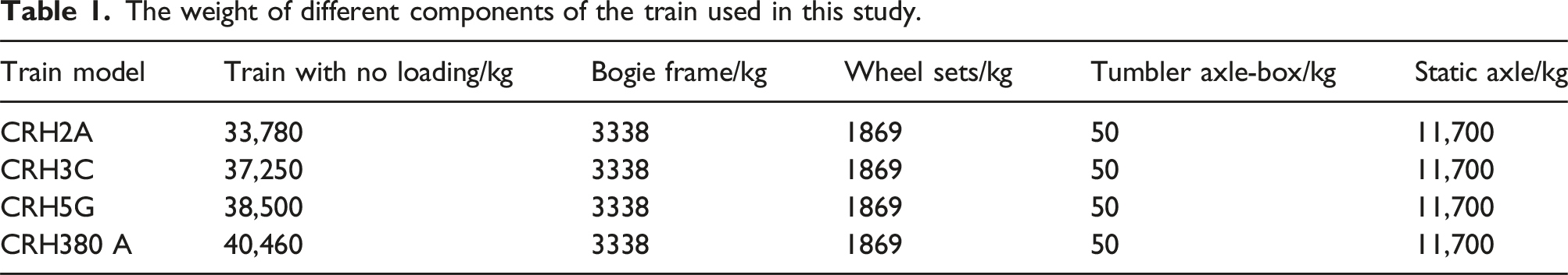
Rigid models of different train models
The weight of different components of the train used in this study.
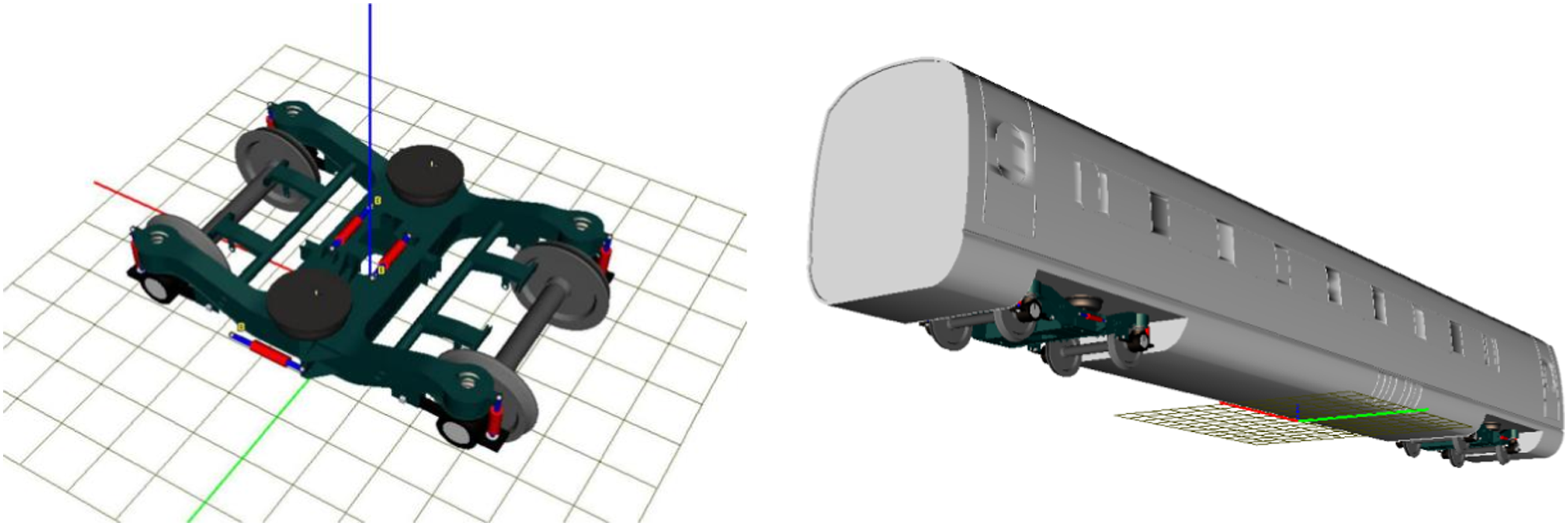
The rigid model of bogie (left) and a single locomotive (right).
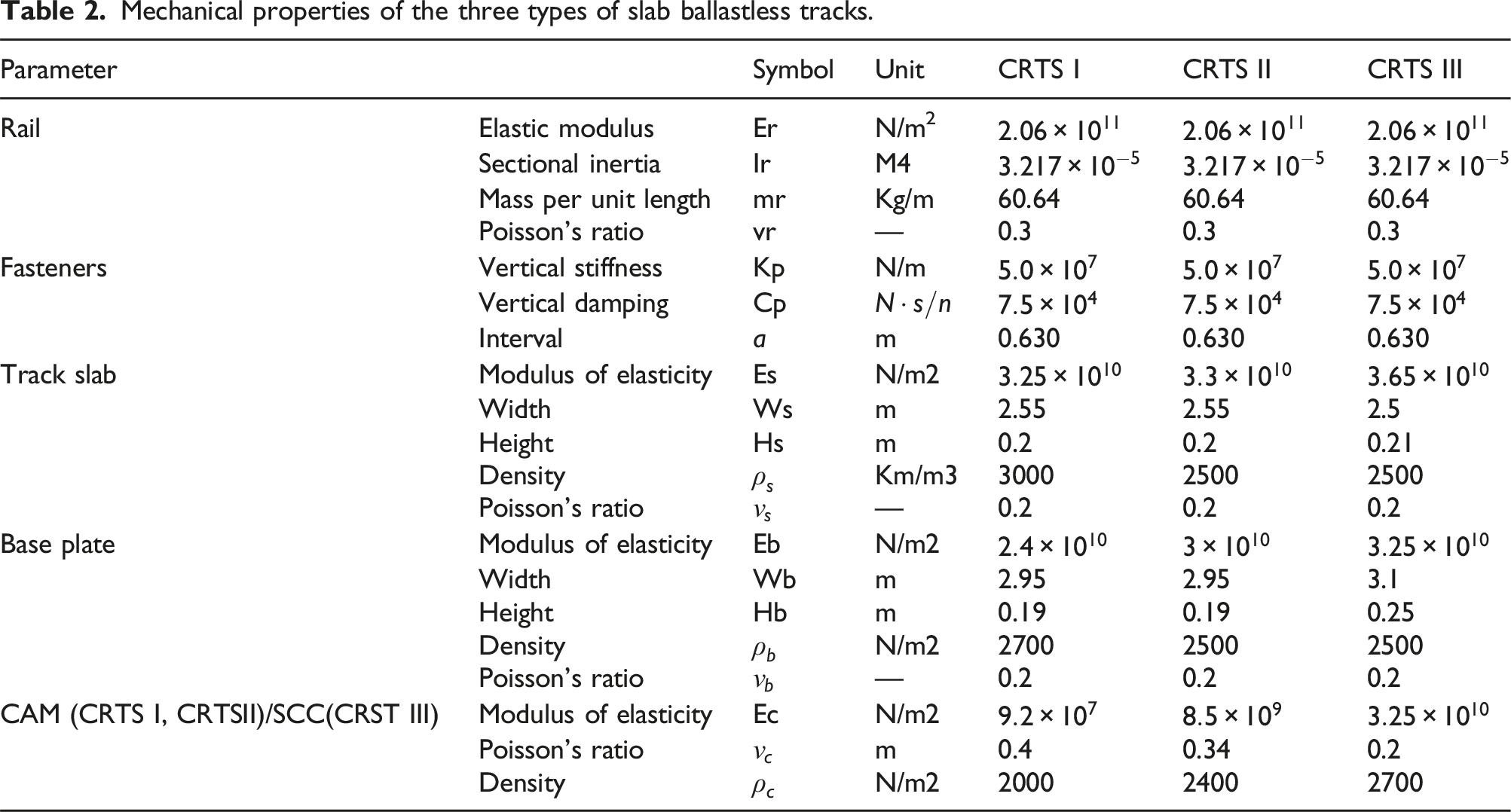
Refined flexible model of the track-bridge structures
Mechanical properties of the three types of slab ballastless tracks.
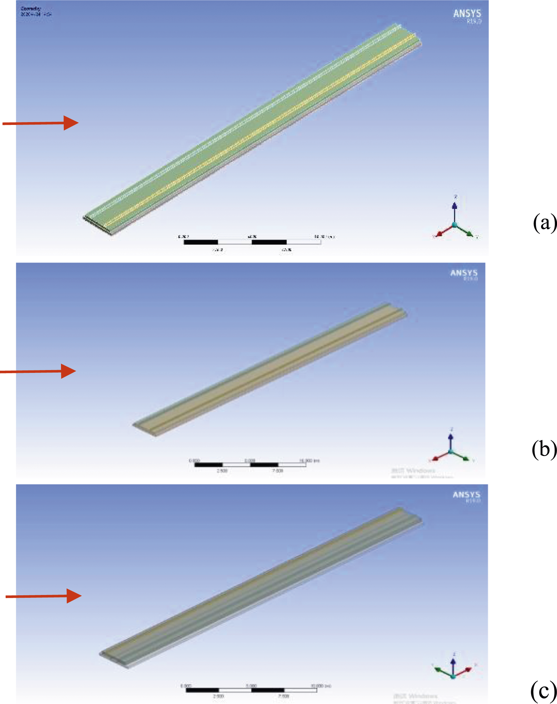
Refined flexible models of slab ballastless tracks: (a) CRTS I; (b) CRTS II; (c) CRTS III.
As shown in Figure 4, the flexible dynamic model of the track-bridge system is composed of a 32 m simply supported prestressed concrete box girder and slab ballastless tracks. The grade C55 concrete is used for the box girder with elastic modulus Flexible models of track-bridge model: 32 m simply supported prestressed concrete box girder (left) and grid of the track-bridge model (right).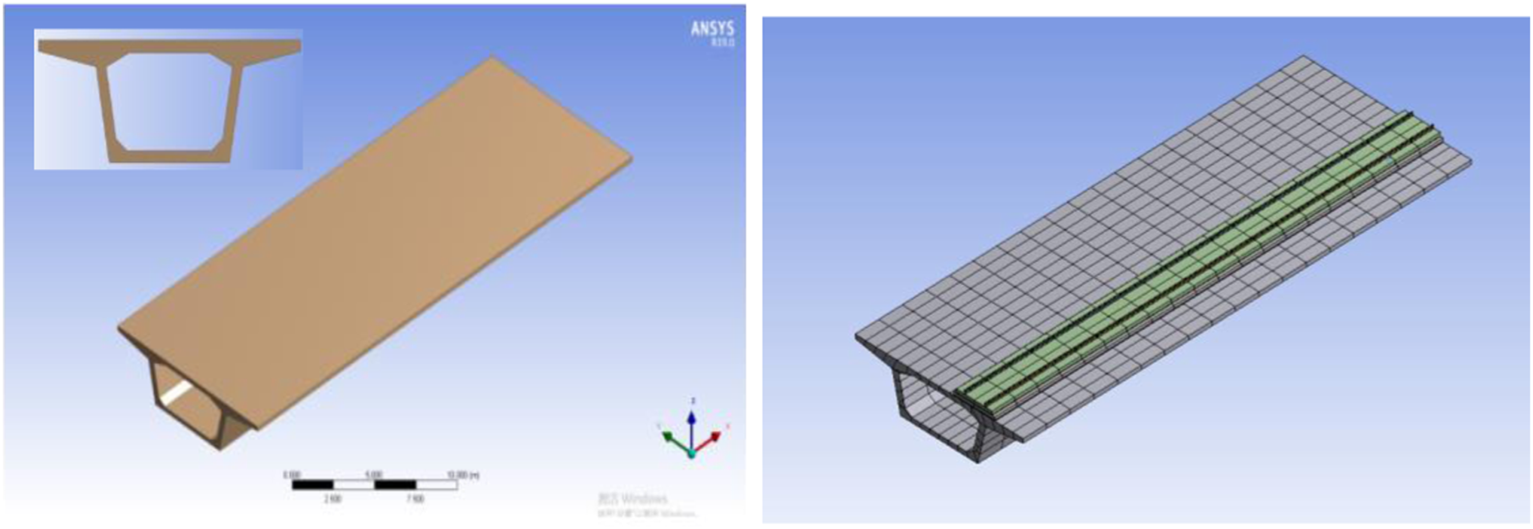
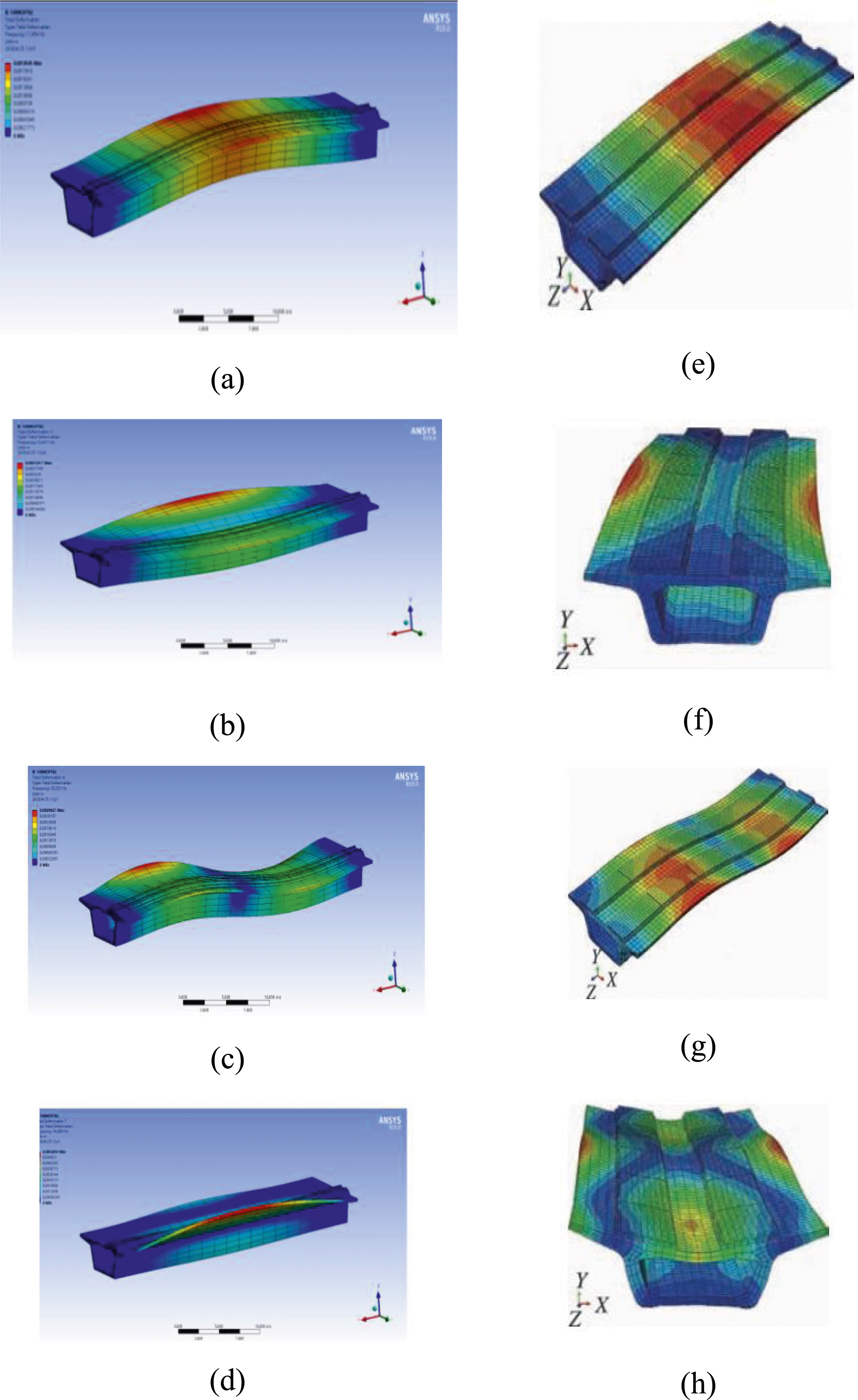
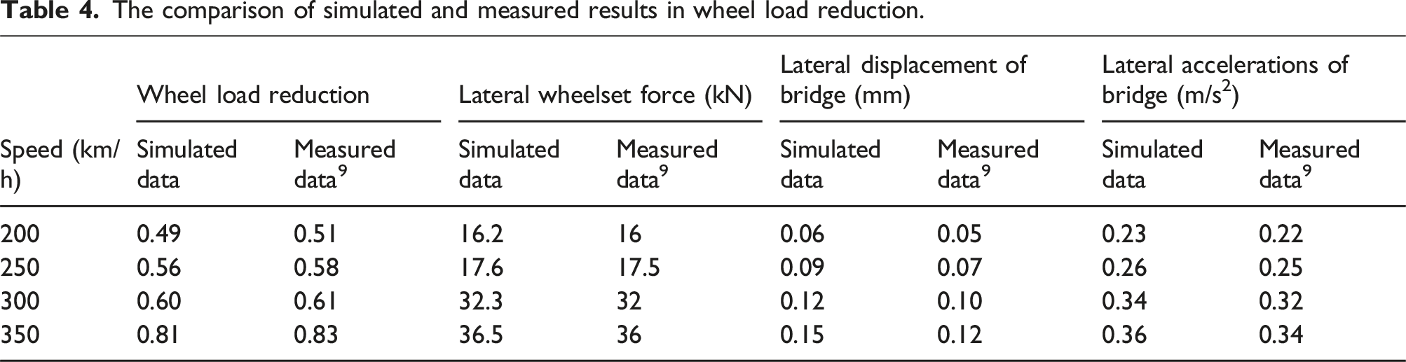
To validate the refined finite element models of the track-bridge structure, the dynamic characteristics of CRTS II track-bridge structures were firstly calculated by the BLOCK LANCZOS method. As shown in Figure 5(a)–(d), the natural frequencies of the first-order symmetrical vertical bending, first-order lateral reverse torsion, anti-symmetric vertical bending, and lateral anti-reverse torsion of CRTS II are 11.45 Hz, 16.41 Hz, 23.33 Hz, and 34.00 Hz, respectively. The experimentally measured CRTS II natural frequencies are 8.88 Hz, 18.19 Hz, 23.03 Hz, and 33.72 Hz in the study of Figure 5(e)–(h), respectively.
23
The reason for these frequency deviations is a result from the difference of a single line on the bridge in our model while two lines on the bridge of Sun’s model. Therefore, the comparison results show that the dynamic characteristics of refined flexible model agree well with the experiment result, which proves that the refined finite element models could reasonably describe the experimentally observed dynamic performance of vehicle-track-bridge. The mode shape of CRTSII track-bridge model: (a) First-order vertical bending vibration; (b) First-order lateral reverse torsion; (c) anti-symmetric vertical bending; (d) lateral anti-reverse torsion; (e–h) The corresponding mode shapes of CRTSII track-bridge model.
23
Refined rigid-flexible coupling models of the vehicle-track-bridge structures
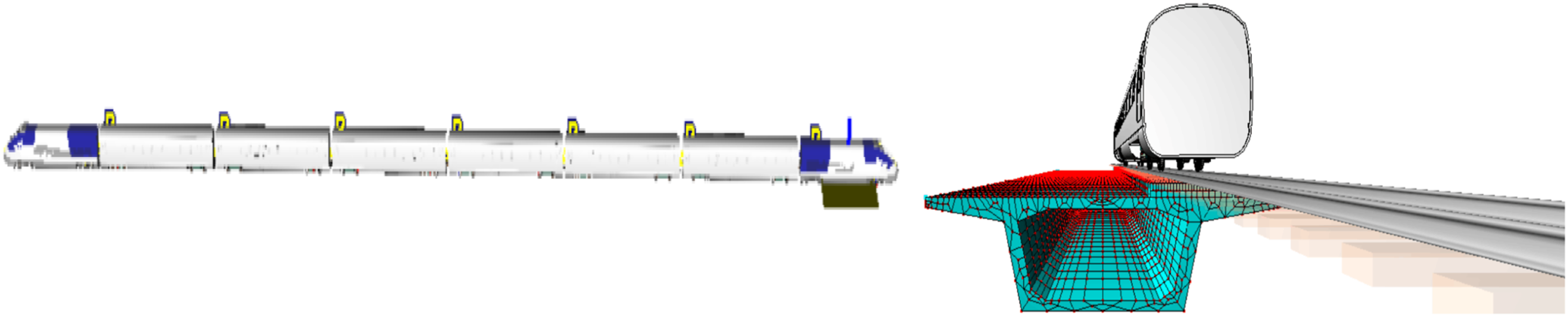
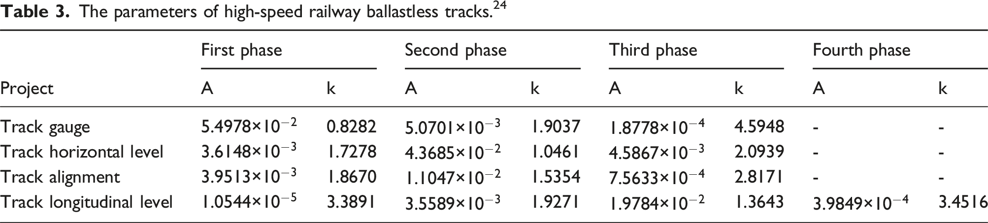
The governing equations of vehicle-track-bridge system were solved by the Newmark-β method to obtain the dynamic response of the system. Figure 6 shows the refined rigid-flexible coupling model of vehicle-track-bridge system with ANSYS and UM with the whole train of eight carriages. In the analysis, the train speed is assumed to be 300 km/h with an initial position of the bridge distance of 32 m and the calculated step of 0.0005 s. Table 3 shows the track irregularity excitation and spectrum obtained from the inversion of the ballastless track irregularity according to specification.
24
The wheel profile is the tread model called LMA, and the steel rail adopts the RAIL60 rail, as well as the PARKPARALLEL algorithm was used to simulate the flexible track system. Refined rigid-flexible coupling models of the vehicle-track-bridge system. The parameters of high-speed railway ballastless tracks.
24
The comparison of simulated and measured results in wheel load reduction.
Dynamic performance of the vehicle-track-bridge
Dynamic indicators of train under various train models
The structural parameters used in modeling dynamic responses of four train models include derailment coefficient, wheel load reduction rate, Sperling index, lateral and vertical acceleration, and wheel-rail lateral and vertical contact forces. Based on the refined rigid-flexible coupling model of the vehicle-track-bridge system, the dynamic responses of four types of high-speed train models are compared with CRH 2, CRH 3, CRH 5, and CRH 380 under the same speed of 200 km/h. Figure 7 shows the safety indexes, smoothness indexes, and dynamic interaction indexes of four trains during operation. It can be seen that the derailment coefficients of CRH 2, CRH 3, CRH 5, and CRH 380 trains are about 0.13 (which are much smaller than the optimum threshold value of 0.6 in Ref. [22]), and the wheel load reduction rates are about 0.5 (which are slight smaller than the allowable value of 0.6). Meanwhile, the lateral and vertical wheel-rail lateral contact force is about 20 KN and 73 KN, respectively. The maximum lateral and vertical accelerations of train models are about 0.25 and 0.95, respectively. Interestingly, the lateral and vertical Sperling indexes are about 0.78 and 0.84, which are much smaller than the optimal allowable value of 2.5. It means the stability requirements are satisfied. With the increase of the body mass of CRH 2, CRH 3, CRH 5, and CRH 380, all the derailment coefficients, the car body accelerations, and Sperling indexes of the train decrease slightly. Although the rate of wheel load reduction and wheel-rail contact force gradually increase, the wheel weight of the load reduction side is lower than the static wheel weight due to the wheel-rail interaction on one or both sides. Dynamic indicators of the train under various train models: (a) Derailment coefficient and wheel load reduction rate; (b) Wheel-rail lateral and vertical contact forces; (c) Lateral and vertical acceleration; (d) Sperling index.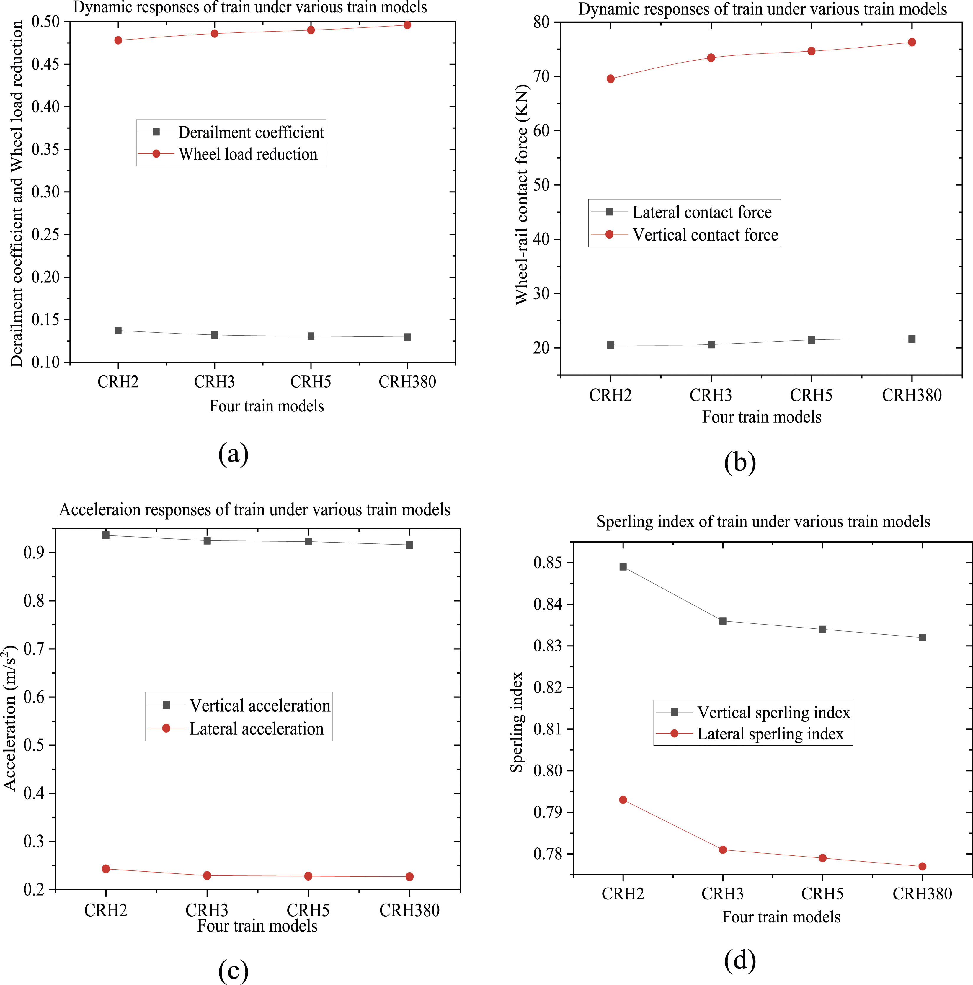
Dynamic indicators of train under various train speeds
Train operation speed is one of the important factors that affect the dynamic performance of the vehicle-track-bridge system. Based on the refined rigid-flexible coupling model of the vehicle-track-bridge system, the dynamic responses of a train need to be further investigated under various train speeds. Five typical train speeds of 200 km/h, 250 km/h, 300 km/h, 350 km/h, and 400 km/h with the interval of 50 km/h were selected, since the train speed of China high-speed railway is defined as larger than 200 km/h, and the maximum train operation speed in future is 400 km/h. The derailment coefficient, wheel load reduction, Sperling index, lateral and vertical acceleration, wheel-rail lateral contact force, and wheel-rail vertical contact force of the CRH380 train under the above five train speeds simulated in the refined model, respectively.
Figure 8 shows the dynamic indicators of the train under various train speeds. Both the derailment coefficient and wheel load reduction gradually increase when the train speed becomes larger, especially at a higher speed of 400 km/h. At the same time, the wheel-rail contact force and accelerations of the train also gradually increase as the train speed increases. As the train speed increases from 250 km/h to 300 km/h, the vertical wheel-rail contact force of the train increases by 24.1%, and the lateral wheel-rail contact force increases by 22.2%. Also, as the train speed increases to 350 km/h, the wheel-rail vertical contact force increased by 20.0% and the wheel-rail lateral contact force increased by 20.3%. Besides, the Sperling index increases with the increase of train speed, and also the train wheel-rail contact force increase could result in significant increase in Sperling index. Thus, the interaction problem between train wheel-rail becomes more prominent with the increase of train speed. In particular, the safety of the train is affected when the speed reaches the range of 350 km/h to 400 km/h. Dynamic indicators of the train under various train speeds: (a) Derailment coefficient and wheel load reduction rate; (b) Wheel-rail lateral and vertical contact forces; (c) Lateral and vertical acceleration; (d) Sperling index.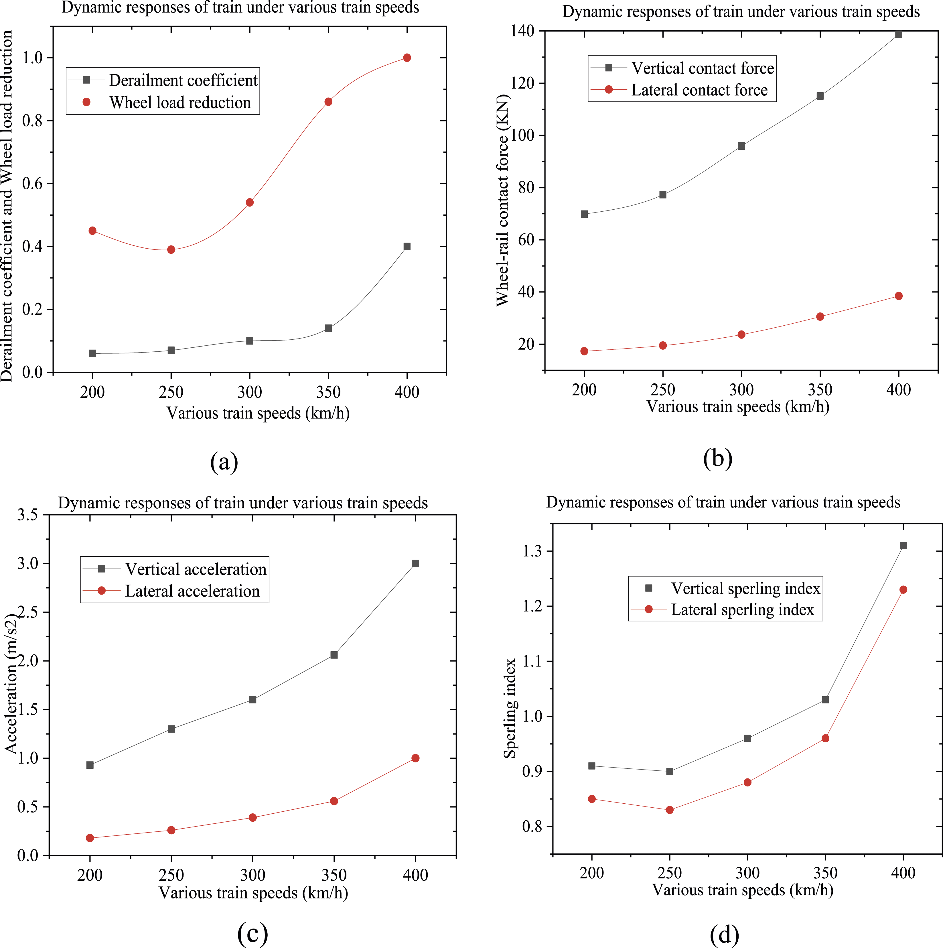
Dynamic indicators of train under various ratios of train loads
The rate of train load in CRH 2.
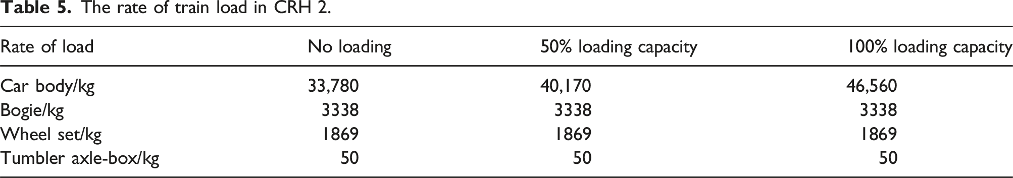
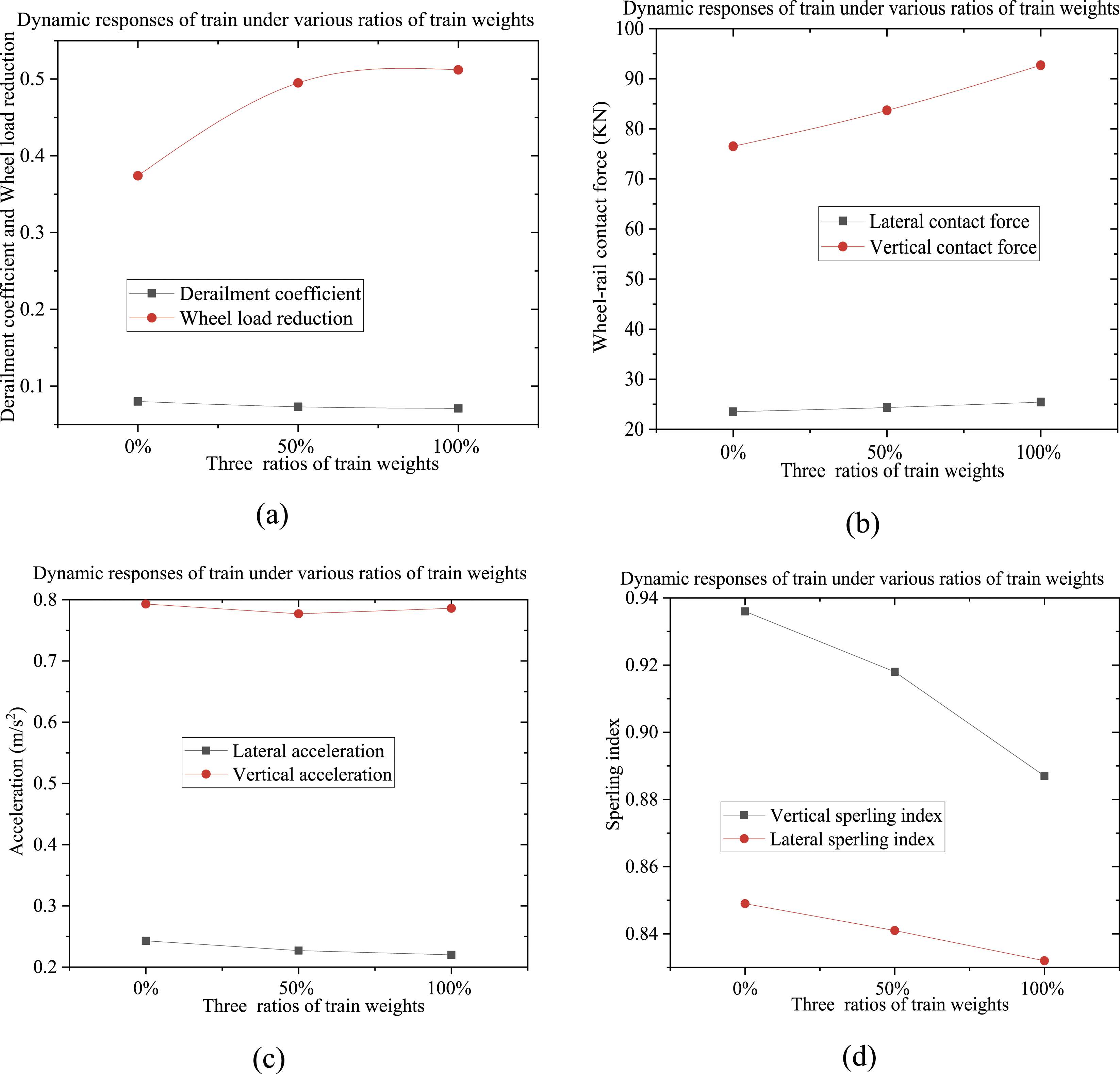
Dynamic indicators of the train with various ratios of train loads: (a) Derailment coefficient and wheel load reduction rate; (b) Wheel-rail lateral and vertical contact forces; (c) Lateral and vertical acceleration; (d) Sperling index.
Dynamic performance of different slab ballastless tracks
Dynamic responses of CRTS I track-bridge structure
Based on the refined rigid-flexible coupling model of the vehicle-track-bridge system, the dynamic responses of the CRTS I track and bridge structures are calculated, respectively. Figure 10 shows the time series of displacement and acceleration of the CRTS I track and box girder. The maximum absolute value in vertical and lateral displacement of the track is 0.69 mm and 0.19 mm, respectively. In detail, the vertical amplitude starts decreasing at the time of 0.25 s and has a short increase during 0.4 s to 0.45 s. Then, it decreases to the minimum value of −0.69 mm at 0.58 s and rebounds to −0.44 mm at 0.68 s. Furthermore, the lateral amplitude increases to a maximum at 0.19 mm within a period of 0.2 s to 0.45 s and has a short decrease to 0.13 mm at 0.58 s. The maximum absolute value of vertical and lateral acceleration of the track is 0.96 m/s2 and 0.89 m/s2, respectively. The vertical acceleration has relatively slight responses and shows the strongest response with −0.88 m/s2 to 0.96 m/s2 during 0.6 s to 0.75 s and gradually decreases as time goes on. The lateral acceleration has relatively slight responses and shows the strongest response with −0.79 m/s2 to 0.88 m/s2 during 0.53 s to 0.72 s and gradually decreases as time goes on. The dynamic responses of ballastless track at CRTS I track-bridge system: (a) Vertical amplitude; (b) Vertical acceleration; (c) Lateral amplitude; (d) Lateral acceleration.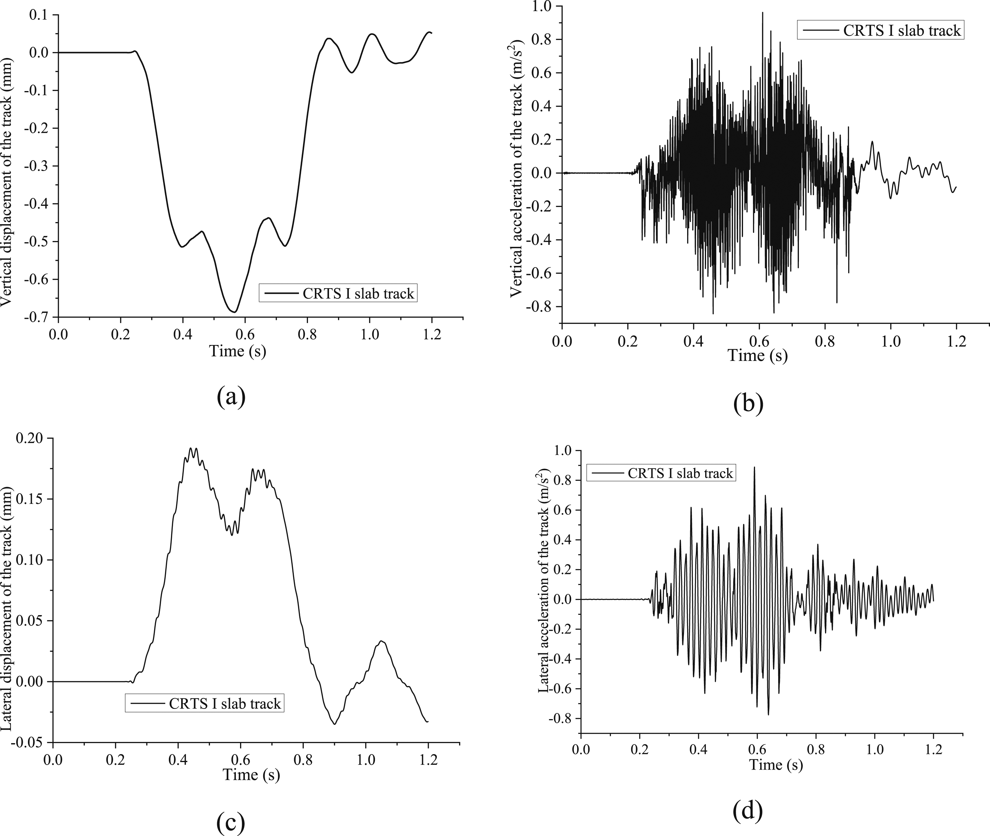
Figure 11 shows the time series of dynamic responses parameters at the box girder bridge within the CRTS I track-bridge system. It shows that the maximum absolute value in vertical and lateral amplitude of the box girder is 0.68 mm and 0.19 mm, respectively. The maximum absolute value in vertical acceleration and lateral acceleration of the box girder is 0.54 m/s2 and 0.23 m/s2, respectively. The vertical amplitude decreases at 0.4 s and has a short increase during 0.4 s to 0.45 s. Then, it decreases to the minimum value of −0.6 mm as shown at 0.58 s and rebounds to −0.44 mm at 0.68 s. The lateral amplitude increases to a maximum at 0.19 mm during the period 0.25 s to 0.45 s and has a short decrease to 0.11 mm at 0.58 s. The vertical acceleration of the box girder shows initial response at 0.22 s and has strong response during 0.37 s to 0.52 s from −0.45 m/s2 to 0.31 m/s2. Then, it has relatively slight responses during 0.51 s to 0.6 s and shows the strongest response with −0.54 m/s2 to 0.45 m/s2 during 0.6 s to 0.9 s and gradually decreases as time goes on. Furthermore, the lateral acceleration shows strong response during 0.25 s to 0.48 s from −0.2 m/s2 to 0.13 m/s2. Then, it has relatively slight responses during 0.48 s to 0.55 s and shows the strongest response with −0.23 m/s2 to 0.23 m/s2 during 0.55 s to 0.72 s and gradually decreases. The dynamic responses of the bridge at CRTS I track-bridge system: (a) Vertical amplitude; (b) Vertical acceleration; (c) Lateral amplitude; (d) Lateral acceleration.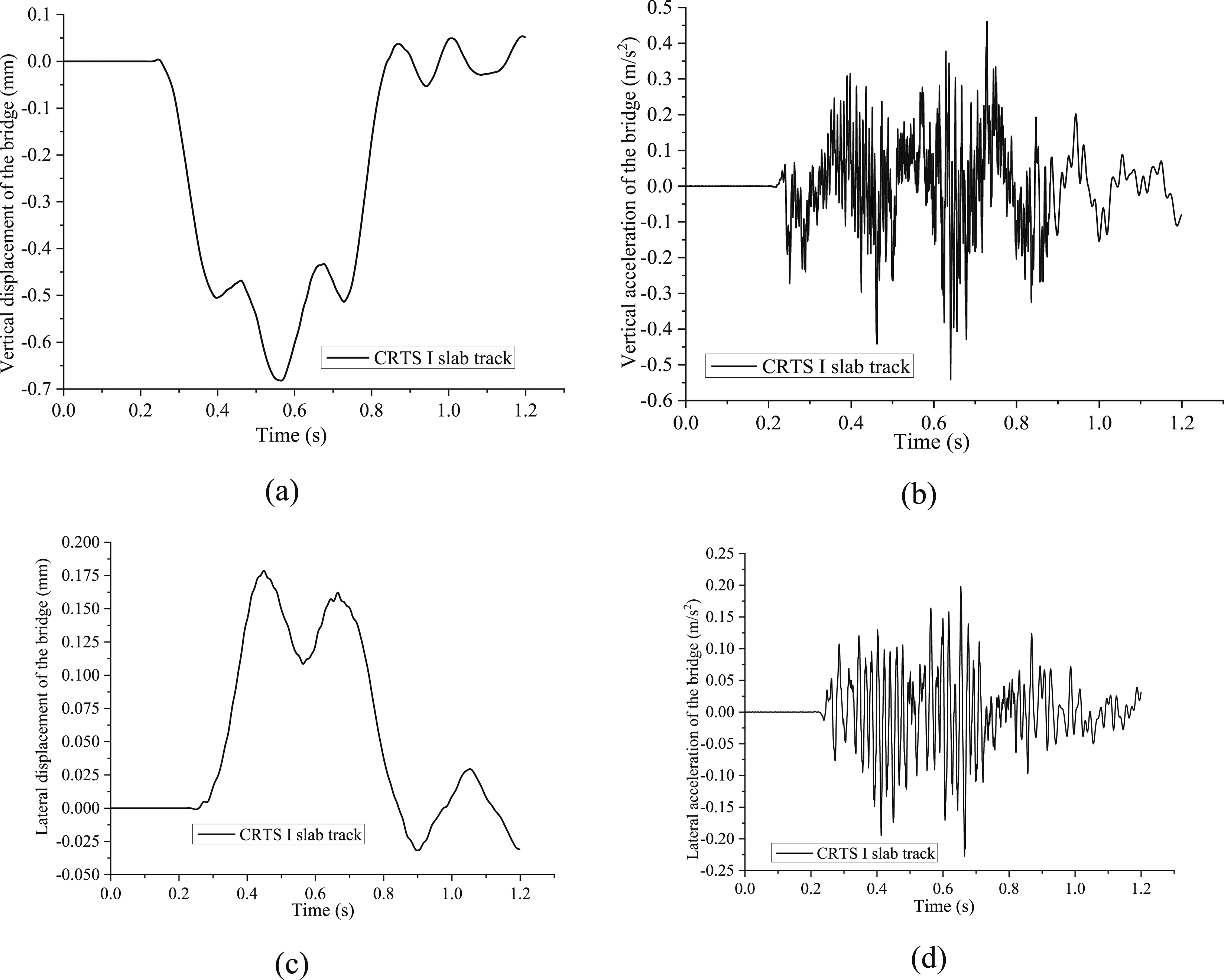
Dynamic responses of CRTS II track-bridge structure
Based on the refined rigid-flexible coupling model of the vehicle-track-bridge system, Figure 12 shows the time series of displacement and acceleration within the CRTS II track and box girder. The maximum absolute value in vertical and lateral displacement of the track is 0.68 mm and 0.18 mm, respectively. The vertical amplitude starts decreasing to −0.52 mm at a time of 0.25 s and has a short increase to −0.48 mm during 0.4 s to 0.45 s. Then, it decreases to the minimum value of −0.68 mm at 0.58 s and rebound to −0.44 mm at 0.68 s, which is closed to the 0.567 mm of the measured maximum displacement of the track. Furthermore, the lateral amplitude increases to a maximum at 0.18 mm within period 0.25 s to 0.42 s and gradually decreases to 0.11 mm at 0.57 s. The maximum absolute value of vertical and lateral acceleration of the track is 1.20 m/s2 and 0.69 m/s2. The vertical acceleration has relatively slight responses during 0.51 s to 0.58 s and shows the strongest response with −1.18 m/s2 to 1.20 m/s2 during 0.58 s to 0.75 s and gradually decreases as time goes on. The lateral acceleration has relatively slight responses during 0.49 s to 0.53 s and shows the strongest response with −0.68 m/s2 to 0.68 m/s2 during 0.53 s to 0.7 s and gradually decreases. The dynamic responses of ballastless track at CRTS II track-bridge system: (a) Vertical amplitude; (b) Vertical acceleration; (c) Lateral amplitude; (d) Lateral acceleration.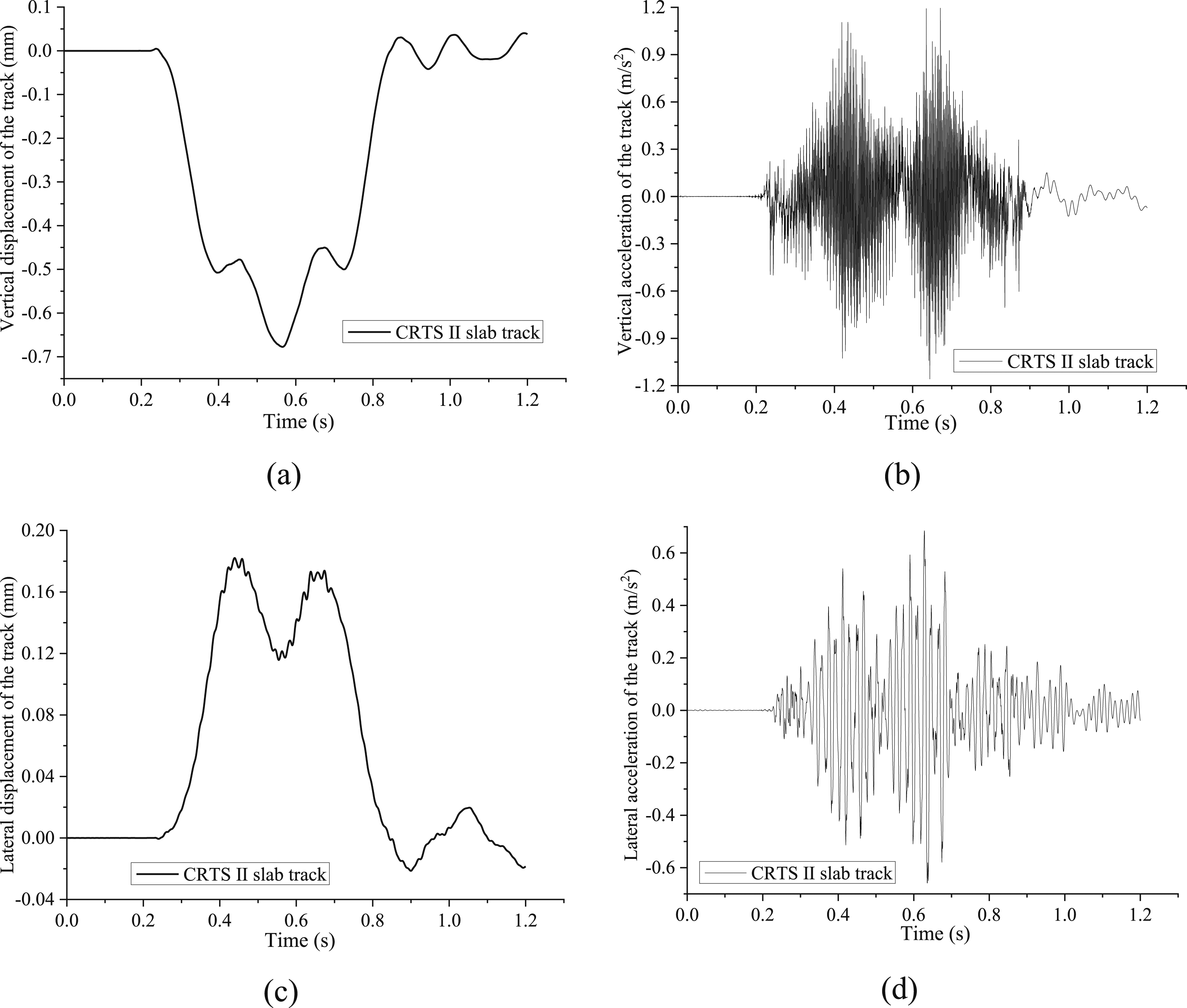
Figure 13 shows the time series of four main dynamic responses parameters at the box girder within the CRTS II track-bridge system (i.e., vertical amplitude and acceleration, lateral amplitude and acceleration). The maximum absolute value in vertical amplitude and acceleration and lateral amplitude and lateral acceleration is 0.67 mm, 0.51 m/s2, 0.18 mm, and 0.19 m/s2, respectively. The vertical amplitude decreases to −0.5 mm at a time of 0.4 s and has a short increase to −0.48 mm during 0.4 s to 0.45 s. Then, it decreases to the minimum value of −0.67 mm at 0.58 s and rebound to −0.45 mm at 0.68 s, which is closed to the 0.565 mm of the measured maximum displacement of the bridge [30]. It decreases to −0.52 mm at 0.72s and rebounds to 0.03 mm at 0.85 s. The lateral amplitude increases to a maximum of 0.18 mm at a period of 0.25 s to 0.45 s and has a short decrease to 0.11 mm at 0.58 s. The vertical acceleration of the box girder has dynamic response starting at 0.22 s and has strong response during 0.32 s to 0.52 s from −0.4 m/s2 to 0.33 m/s2. Then, it has relatively slight responses during 0.52 s to 0.58 s and shows the strongest response with −0.514 m/s2 to 0.45 m/s2 during 0.58 s to 0.88 s and gradually decreases as time goes on. The lateral acceleration shows strong response during 0.32 s to 0.49 s from −0.16 m/s2 to 0.11 m/s2. Then, it has relatively slight responses during 0.49 s to 0.55 s and shows the strongest response with −0.19 m/s2 to 0.13 m/s2 during 0.55 s to 0.88 s and gradually decreases. The dynamic responses of the bridge at CRTS II track-bridge system: (a) Vertical amplitude; (b) Vertical acceleration; (c) Lateral amplitude; (d) Lateral acceleration.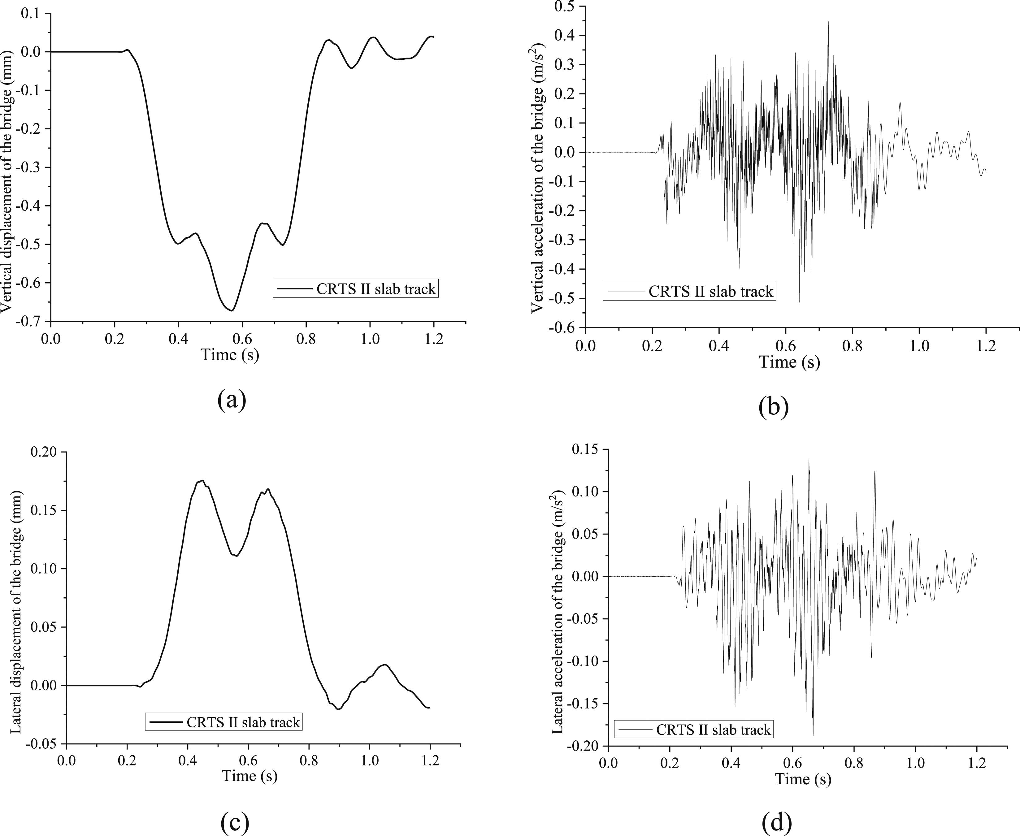
Dynamic responses of CRTS III track-bridge structure
Based on the refined rigid-flexible coupling model of the vehicle-track-bridge system, Figure 14 shows the time series of displacement and acceleration of the CRTS III track and box girder. The maximum absolute value is 0.67 mm, 0.77 m/s2, 0.18 mm, and 1.35 m/s2 with CRTS III ballastless track, respectively. The vertical amplitude starts decreasing to −0.5 mm at a time of 0.4 s and has a short increase to −0.45 mm during 0.4 s to 0.43 s. Then, it decreases to the minimum value of −0.67 mm at 0.58 s and rebounds to −0.42 mm at 0.68 s. Following, it decreases to −0.5 mm at 0.72 s and rebounds to 0.03 mm at 0.85 s. Furthermore, the lateral amplitude increases to a maximum at 0.18 mm within the period 0.25 s to 0.42 s and gradually decreases to 0.11 mm at 0.57 s. The maximum absolute value of vertical and lateral acceleration of the track is 0.77 m/s2 and 1.35 m/s2. The vertical acceleration has slight responses during 0.55s to 0.6s and shows the strongest response with −0.65 m/s2 to 0.77 m/s2 during 0.6 s to 0.9 s and gradually decreases as time goes on. The lateral acceleration has relatively slight responses during 0.30 s to 0.50 s and shows the strongest response with −0.61 m/s2 to 0.65 m/s2 during 0.55s to 0.65s and gradually decreases. The dynamic responses of ballastless track at CRTS III track-bridge system: (a) Vertical amplitude; (b) Vertical acceleration; (c) Lateral amplitude; (d) Lateral acceleration.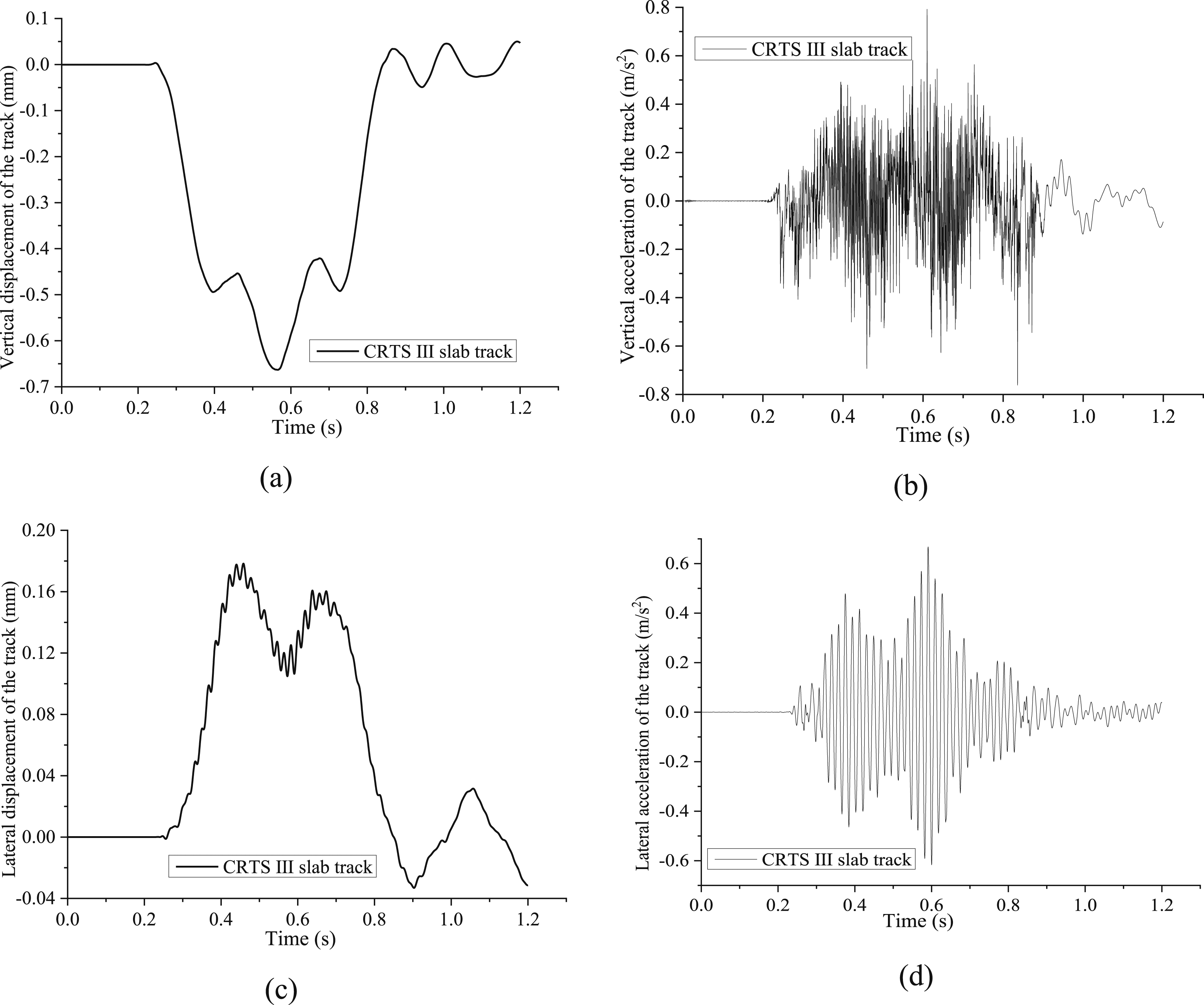
Figure 15 shows the dynamic response at the main beam within the CRTS III track-bridge system. The maximum absolute value in displacement and acceleration is 0.66 mm, 0.47 m/s2, 0.17 mm, and 0.24 m/s2, respectively. The vertical amplitude decreases to −0.5 mm at a time of 0.4 s and has a short increase to −0.45 mm during 0.4 s to 0.45 s. Then, it decreases to a minimum value of −0.66 mm at 0.58 s and rebound to −0.42 mm at 0.68 s. Following, it decreases and rebounds during 0.72 s to 0.85 s. The lateral amplitude increases to a maximum of 0.17 mm at the time period 0.25 s to 0.45 s and has a short decrease to 0.11 mm at 0.58 s. Then, it increases to the value of 0.15 mm at 0.68 s and directly decreases to −0.04 mm at 0.9 s. Following, it decreases at 0.025 mm with 1.05 s and gradually decreases till 1.2 s. The vertical acceleration of the box girder has dynamic response starting at 0.22 s and has strong response during 0.35 s to 0.52 s from −0.45 m/s2 to 0.28 m/s2. Then, it has relatively slight responses during 0.52 s to 0.58 s and shows the strongest response with −0.47 m/s2 to 0.39 m/s2 during 0.58 s to 0.88 s and gradually decreases as time goes on. The lateral acceleration shows strong response during 0.32 s to 0.52 s from −0.22 m/s2 to 0.18 m/s2. Then, it has relatively slight responses during 0.52 s to 0.55 s and shows the strongest response with −0.24 m/s2 to 0.24 m/s2 during 0.55 s to 0.88 s and gradually decreases. The dynamic responses of the bridge at CRTS III track-bridge system: (a) Vertical amplitude; (b) Vertical acceleration; (c) Lateral amplitude; (d) Lateral acceleration.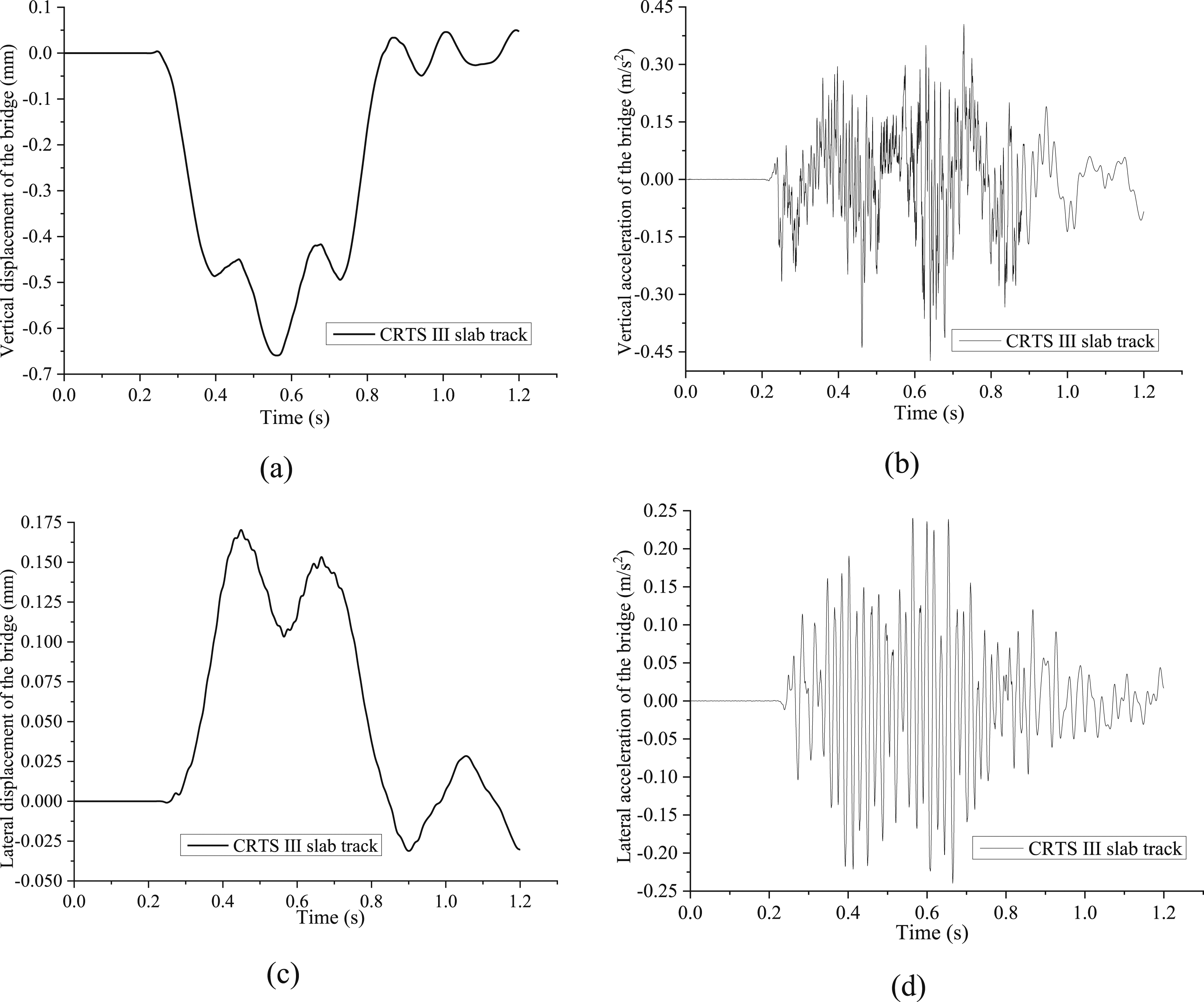
Dynamic responses comparison of three slab tracks
The maximum dynamic response comparison of the train under three types of tracks.
The dynamic responses comparison under the speed of 300 km/h is shown in Figure 16, and the maximum lateral and vertical displacements in the bridge span are about 0.18 mm and 0.68 mm, respectively. It shows the vibration amplitude is relatively small. The lateral and vertical accelerations of the rail-bridge system are 0.20 m/s2 and 0.50 m/s2, respectively. Moreover, Figure 16 shows the value of various dynamic responses from the track-bridge system also satisfied with the safety requirements. In summary, the dynamic performance of the ballastless track follows the descending order: CRTS III slab ballastless track, CRTS II slab ballastless track, and CRTS I slab ballastless track. Furthermore, the wheel load reduction and the horizontal and vertical acceleration of the CRTS III slab ballastless track are slightly greater than CRTS II and CRTS I slab ballastless track. The CRTS III ballastless track is proved to have a better dynamic response in the vehicle-track-bridge system. The maximum responses comparison under three types of track-bridge structures: (a) Lateral displacement response; (b) Vertical displacement response; (c) Acceleration in track structures; (d) Acceleration in bridge structures.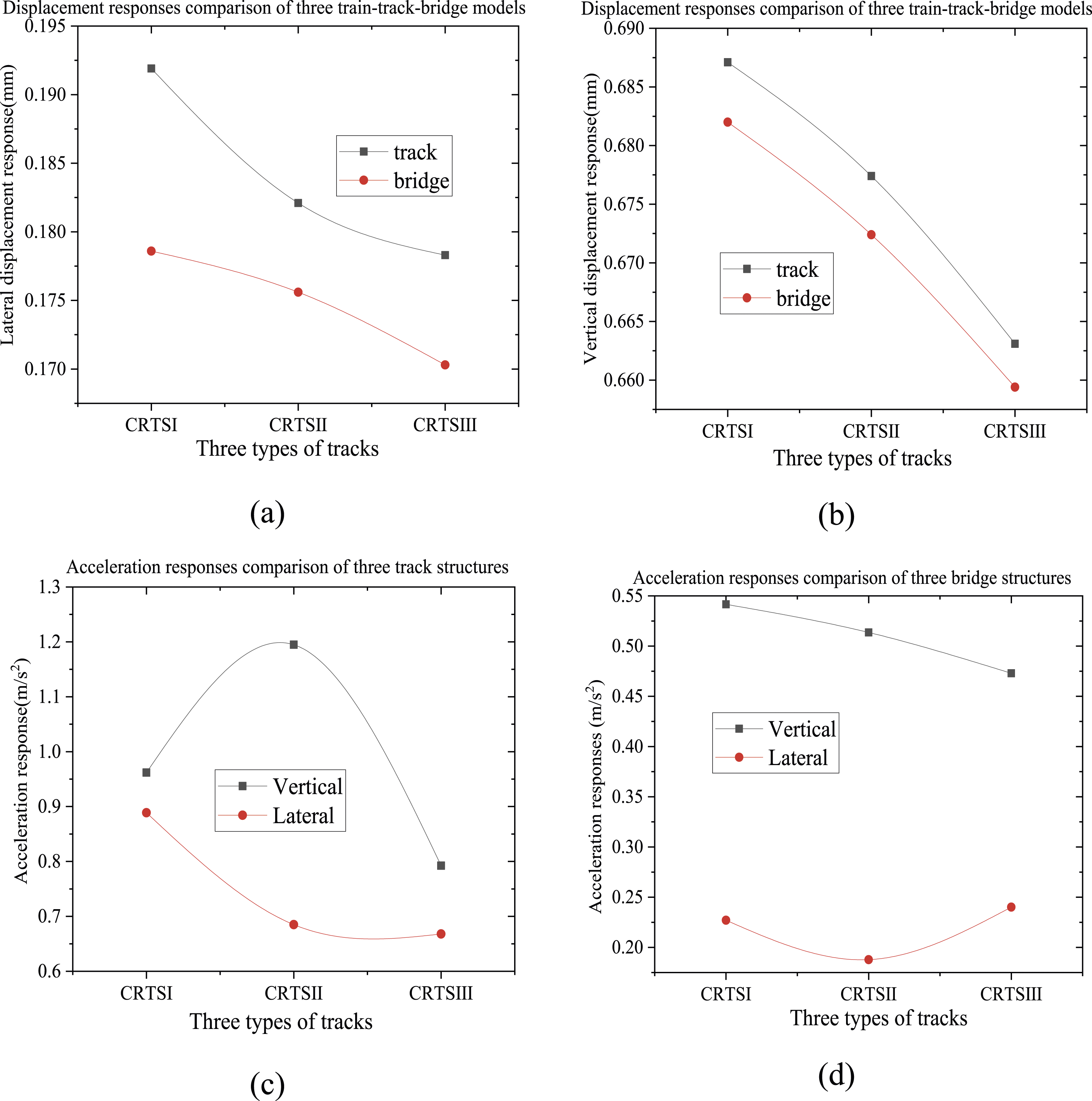
Conclusions
This paper developed the refined rigid-flexible coupling models of vehicle-multi-layer slab track-bridge based on the combination of ANSYS and Universal Mechanism. The dynamic responses of the train and slab track-bridge structures under various train loads were compared. The major conclusions are as follows: (1) The refined rigid-flexible coupled model could effectively simulate the dynamic performance of the vehicle-track-bridge with multi-layer slab track structures; (2) As the train speed increases from 200 km/h to 400 km/h, the parameters of derailment system, vertical and lateral acceleration, the wheel-rail contact force, and Sperling index also become larger, especially when the speed increases to 350 km/h. (3) As the weight of the train increases, the derailment coefficient, lateral and vertical acceleration, and the Sperling index are gradually decreases, while the wheel load reduction rate slowly increases to about 0.5. Furthermore, the lateral force of the wheel axle and the wheel-rail vertical force gradually increases, of which the train safety will be threatened when the train load is 100% loading capacity. (4) The derailment coefficient, wheel load reduction, and vertical and lateral acceleration of the train in the vehicle-track-bridge of CRTS II slab track are larger than those of the CRTS I or CRTS III slab track. Both the displacement and acceleration responses of the track-bridge structures of the CRTS III slab track are slightly smaller than those of CRTS II and CRTS I slab track.
This study mainly compared the dynamic performance of vehicle-track-bridge system with three slab track structures under various train loads without considering structural damage. In the future, the influence of the interface damage of ballastless tracks and the thermal-mechanical effects on the dynamic performance needs to be further explored. Therefore, further research will focus on the complex coupling effect temperature and train loads, and the effects of interface damage on the dynamic performance of the whole vehicle-track-bridge system.
Footnotes
Declaration of conflicting interests
The author(s) declared no potential conflicts of interest with respect to the research, authorship, and/or publication of this article.
Funding
The author(s) disclosed receipt of the following financial support for the research, authorship, and/or publication of this article: The authors gratefully acknowledge support from the National Key Technologies Research and Development Program (No. 2022YFB2603301), National Natural Science Foundation of China (No. 52278311 and 52008264), the Shenzhen Science and Technology Program (No. GJHZ20220913143006012 and GJHZ20200731095802007), in part by the Foundation of Key Laboratory of Large Structure Health Monitoring and Control in Hebei Province under Grant KLLSHMC2108, the State Key Laboratory of Mountain Bridge and Tunnel Engineering (No. SKLBT-ZD2101), Guizhou University Talent Project [2022]68, Guizhou Provincial Basic Research Program (Natural Science) (No. QianKeHeJiChu-ZK[2024]YiBan070), MOE Key Laboratory of High-Speed, Railway Engineering, Southwest Jiaotong University: 2021 Open Fund. Project of Science and Technology Research and Development Program of China Railway Corporation (No. K2022G038 and N2022G033), Guangdong Province Natural Science Foundation (No. 2022A1515010665), National Key Laboratory of Green and Long-Life Road Engineering in Extreme Environment (Shenzhen University), Ministry of Education.