
Abstract
A simplified model of the absorption coefficient of traditional Helmholtz resonators (THR) was established, and the influence of different geometric parameters on the absorption coefficient of THR was analyzed. To realize the low-frequency broadband acoustic structure design, an accurate theoretical model for the sound absorption coefficient of the curled acoustic metasurface (CAM) unit was established. Based on the complex frequency plane method (CFPM), the CAM units with perfect sound absorption at four discrete frequencies were designed. The low-frequency broadband acoustic metasurfaces in parallel under decoupled and coupled conditions were studied, and the thickness is only 12 mm. The high efficiency of sound absorption above 0.8 was achieved in the frequency range of 758 Hz–940 Hz. The experiment verifies the efficient sound absorption effect of the CAM unit and the broadband sound absorption effect under coupled conditions. The research in this paper has a certain potential applications for low-frequency broadband noise control technology.
Keywords
Introduction
Noise control, especially low-frequency wideband noise control technology, has always been a hot and difficult issue in scientific research and engineering application.1–3 Traditional acoustic materials, such as porous materials and microperforated plates, can achieve high-efficiency noise absorption at medium and high frequencies,4–6 but their low-frequency sound absorption capacity is limited by thickness. 7 In order to achieve low frequency and efficient sound absorption, bulky materials and structures are often required, 8 which greatly limits the application of traditional acoustic structures in the engineering field. The Helmholtz resonator can achieve low-frequency noise absorption,9–11 but due to the local resonance mechanism, their efficient sound absorption bandwidth is relatively narrow.
The appearance of acoustic metamaterials has opened up a new direction for low-frequency broadband noise control. Acoustic metamaterials are acoustic materials or structures composed of specially designed artificial acoustic micro-geometric units periodically arranged in elastic media, which have the characteristics of controlling large wavelength with small size.12–16 Acoustic metasurface is a kind of acoustic metamaterial whose thickness is negligible relative to wave length, and is one of the important branches of acoustic metamaterial.17–21 They developed from the initial membrane metamaterial to the metasurface with Helmholtz resonator as the main structure.22–24 The Helmholtz resonator can not only be used for sound absorption, but also widely used in fields such as combustion stability and aerodynamic noise control.25–28
In order to achieve efficient low-frequency broadband sound absorption, the Helmholtz resonator cavity is usually compressed to study acoustic metasurfaces with subwavelength/depth subwavelength characteristics.3,29–35 In terms of structural characteristics, the sound absorbing metasurface can be divided into two categories: bending and curled. Among them, the bending acoustic metasurface replaces the cavity of Helmholtz resonator with a bending structure, which has subwavelength sound absorption characteristics and weak coupled between units, and can achieve high-efficiency sound absorption with low-frequency broadband, but its thickness is relatively thick.3,29–31The curled acoustic metasurface replaces the cavity of Helmholtz resonator with a curled structure, which has deep subwavelength characteristics and strong coupled between units, and can achieve low-frequency broadband sound absorption at ultra-thin thickness, but its efficient sound absorption bandwidth is relatively narrow.32–35
In order to simultaneously achieve ultra-thin thickness and low-frequency broadband efficient sound absorption metasurfaces, and further analyze the sound absorption mechanism and characteristics of metasurfaces under coupled and decoupled conditions, firstly, based on the simplified model of the absorption coefficient for THR unit by the transfer-matrix method, the influence of different geometric parameters on the absorption coefficient of the THR is analyzed. Then, in view of the shortcomings of THR unit in low-frequency broadband sound absorption, the CAMs with deep subwavelength characteristics are proposed. The theoretical model of sound absorption coefficient for the CAMs is established and the low-frequency broadband acoustic metasurface is designed in decoupled and coupled conditions. Finally, the sound absorption effects of the CAM unit and the composite CAM in the coupled conditions are verified by experiments. Finally, the paper is discussed and summarized.
Simplified model of traditional Helmholtz resonators
Although the frequency corresponding to the sound absorption peak can be shifted to the lower frequency by controlling the neck length of the HR unit, the longer the neck length means that the overall geometric thickness of the HR unit is thicker, which undoubtedly limits its application in the field of vibration and noise reduction. Assuming geometric parameters of THR include neck radius r
n
, neck length l
n
, cavity radius r
c
, cavity length l
c
, and radiation space radius r
t
. The structure diagram and sizes of the THR unit are shown in Figure 1(a) and Figure 1(b). Traditional Helmholtz resonator (a) structure diagram of THR; (b) geometric parameters of the THR; (c) the relationship between neck length and absorption coefficient of THR.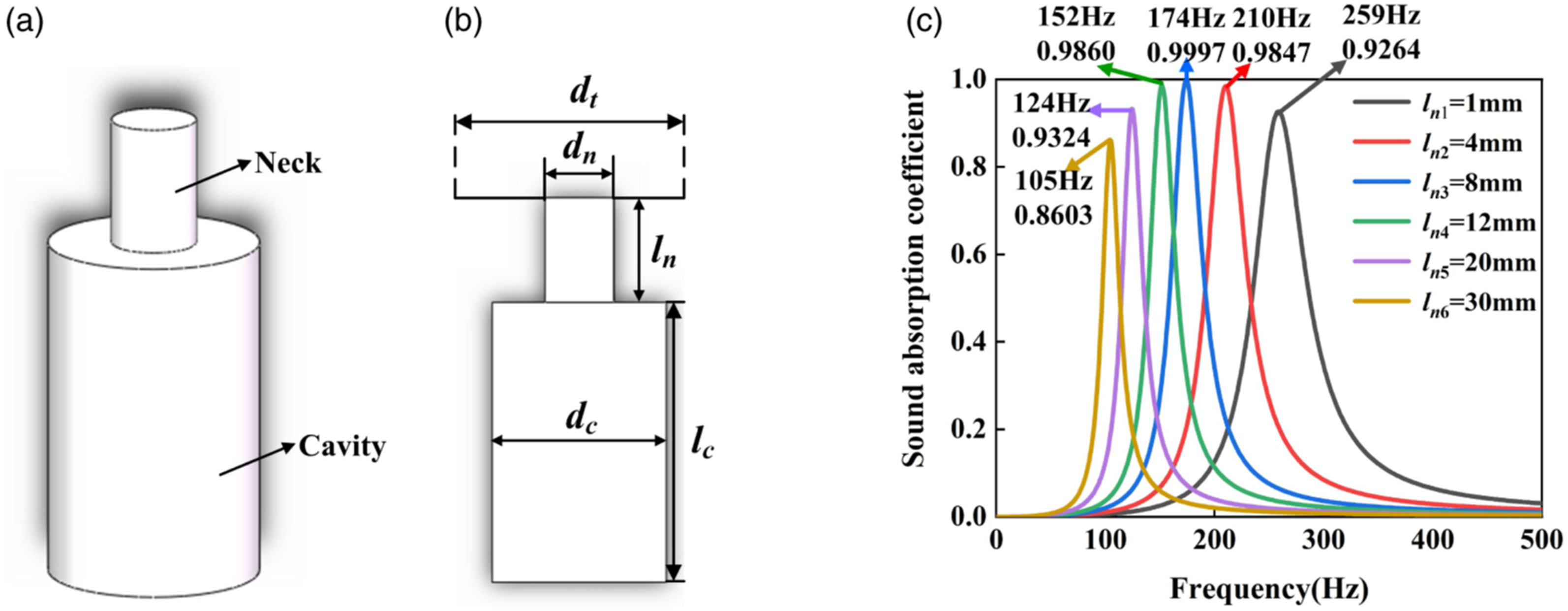
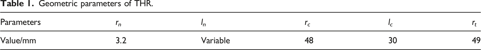
Geometric parameters of THR.
Thermal viscosity equivalent model
When sound waves propagate through the neck and cavity of the THR unit, a strong thermal adhesion effect is generated due to the small diameter of the neck and cavity. 

End acoustic radiation correction model
As sound waves propagate from the neck to the cavity and outer space, the discontinuous interface causes radiation acoustic impedance. The radiation acoustic impedance needs to be corrected, and the correction length is expressed as36,37

Simplified model of traditional Helmholtz resonators unit
Assuming that the sound pressure on the left and end of the THR unit is p1 and p2, and the normal sound velocity is v1 and v2, respectively, the sound wave propagation equation of THR unit can be written as follows:36,37
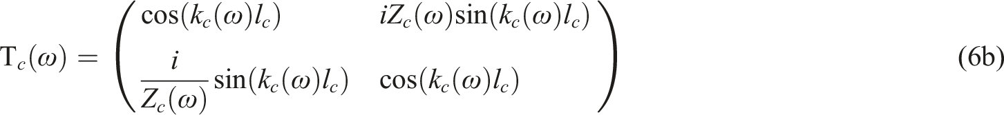
Here, the transfer matrices of the neck and cavity are written as follows:36,37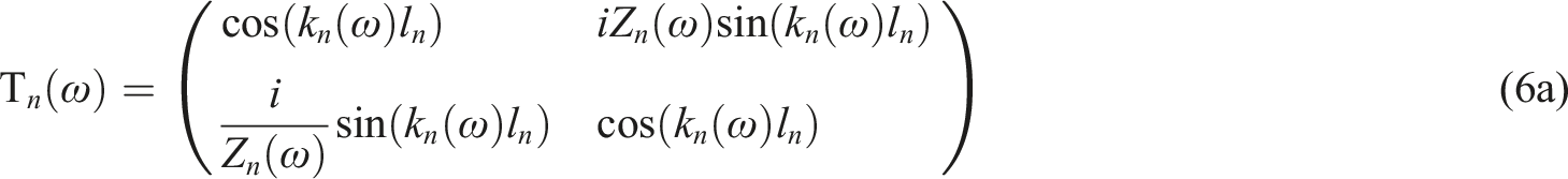
The end length correction matrix can be written as36,37
Due to the closed end of the THR unit, there is 


A simplified model for calculating the sound absorption coefficient of THR unit can be obtained by combining formulas (1)–(9). Substitute the geometric parameters in Table 1 into the simplified model, and change the neck length l n to obtain the sound absorption coefficients of the different THR units, as shown in Figure 1(c).
From Figure 1(c), it can be seen that when the thickness of the cavity is 30 mm and the neck length changes from 1 mm to 30 mm, the corresponding frequency range of the absorption peak range from 105 Hz to 259 Hz, and the range of the absorption peak range from 0.8603 to 0.9997. The efficient sound absorption frequency bands for THR units are relatively narrow, indicating that THR units can only achieve efficient sound absorption in low-frequency narrow bands, and the thickness is relatively thick, which limits the application of THR in low-frequency noise reduction. Considering that the acoustic performance of THR unit is highly sensitive to the neck length, it can be considered to compress the neck and cavity in space to achieve the design of acoustic metamaterial with subwavelength characteristics.
Deep subwavelength curled acoustic metasurface
In the study of THR unit, when the total thicknesses are 31 m–61 mm, the corresponding frequencies of the sound absorption peak are 105 Hz–259 Hz. In order to achieve a lower frequency broadband sound absorption structure design and alleviate the over-resistance problem when multiple units are connected in parallel to achieve broadband sound absorption, we proposed a CAM with deep subwavelength thickness, and the structure is shown in Figure 2. The CAM replaces the acoustic impedance provided by the cavity through curled channel, which allows for the expansion of the cavity with a larger z-value in the three-dimensional space of xyz through spatial curled. Schematic diagram of CAM.
Theoretical modeling of curled acoustic metasurface units
The temperature change has a significant impact on the equivalent acoustic impedance of the Helmholtz resonator.38–40 Due to the small embedded hole in the CAM unit designed in this paper, the strong thermal viscous loss effect of the embedded aperture needs to be considered when calculating the equivalent acoustic impedance of the CAM unit. Geometric parameters of the CAM are shown in Figure 2, the radius is r
a
, the width of curled channel is w, and the height is h. The diameter of the embedded hole is d
n
, the height of the embedded hole is l
n
, the equivalent length of the equal cross-section curled channel is L, and the equivalent length of the variable cross-section curled channel is L1. The total impedance of the CAM unit is 


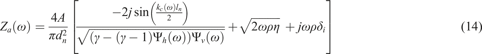
The total acoustic impedance of CAM unit with embedded holes can be expressed as
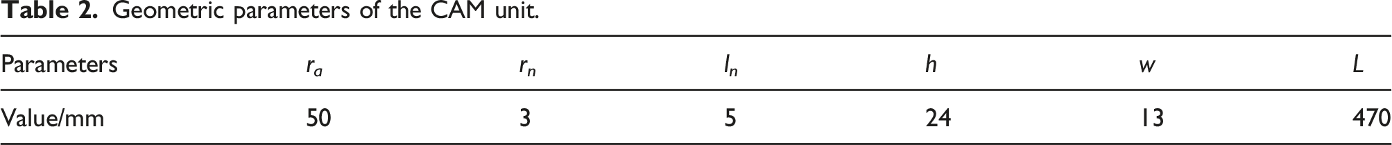
Geometric parameters of the CAM unit.
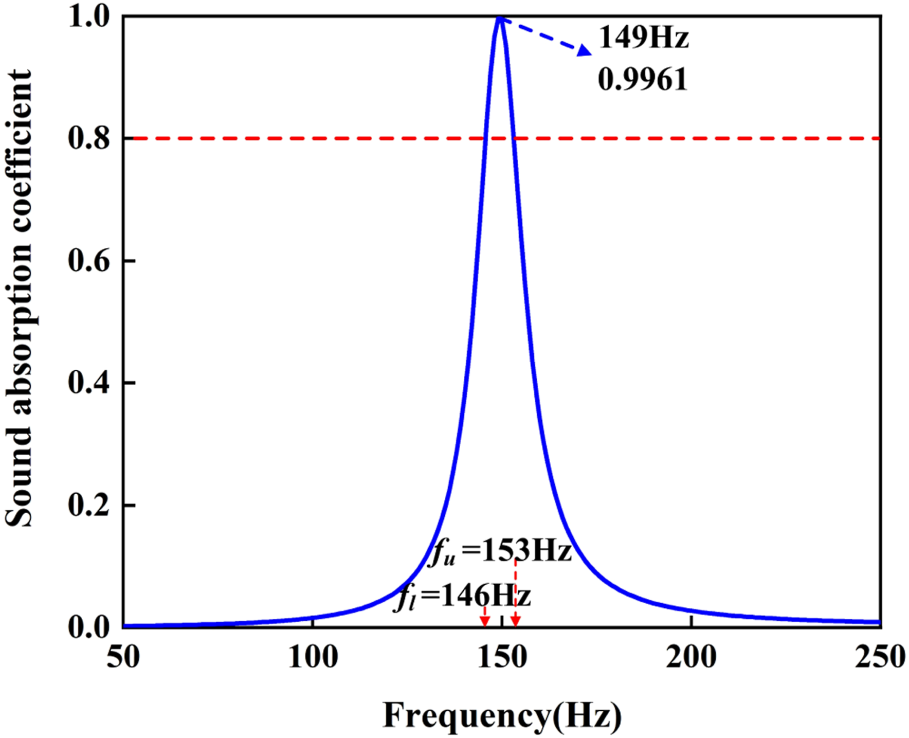
Sound absorption coefficient of CAM unit.
As can be seen from Figure 3, the cavity in the CAM unit is replaced by a curled channel, and the thickness is significantly reduced. The CAM unit after thickness compression can achieve 0.9961 perfect sound absorption at 149 Hz. However, compared with the THR unit, the efficient sound absorption band with a sound absorption coefficient above 0.8 is 146 Hz–153 Hz, which narrows the efficient sound absorption band.
To further analyze the control law of geometric parameters on the sound absorption performance of CAM units, for the geometric parameters in Table 2, keeping the other five geometric parameters unchanged, and changing one of the geometric parameters in gradient to get the influence of six parameters on the CAM units, as shown in Figure 4. The influence of geometric parameters for CAM units on sound absorption coefficients (a) radius r
a
; (b) embedded hole radius r
n
; (c) embedded hole length l
n
; (d) the height of the curled channel h; (e) curled channel width w; (f) equivalent length L of curled channel.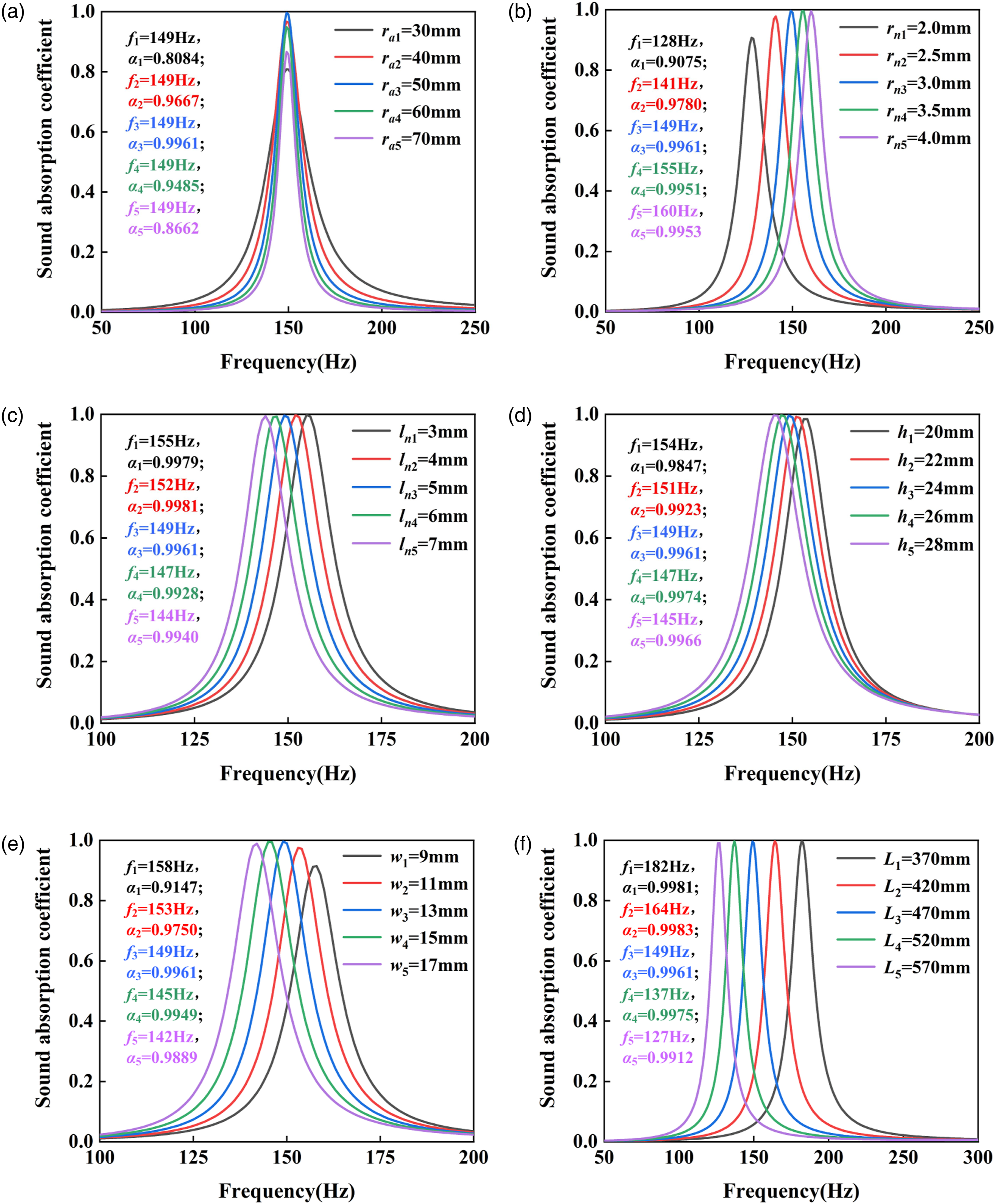
From Figure 4(a), when ra3 = 50 mm, the CAM unit is in perfect sound absorption state, and achieving sound absorption coefficient of 0.9961 at 149 Hz. When r a decreases from 50 mm to 40 mm and 30 mm, the structure is in a state of under-resistance, and the perfect sound absorption state is destroyed. The sound absorption coefficient peak becomes 0.9667 and 0.8084. When r a increases from 50 mm to 60 mm and 70 mm, the structure is in an over-resistance state, and the sound absorption coefficient peak changes to 0.9485 and 0.8662. It can be seen that the change in radiation radius r a only affects the radiation acoustic resistance, but does not affect the acoustic reactance (frequency unchanged). Therefore, the optimization of the sound absorption coefficient can be achieved by adjusting the radiation radius of the CAM unit.
From Figure 4(b), it can be seen that adjusting the neck length r n can achieve the adjustment of acoustic impedance. Using rn3 = 3.0 mm as a reference, perfect sound absorption of 0.9961 is achieved at 149 Hz. When r n decreases to 2.5 mm and 2 mm, due to the reduction of the neck radius, the equivalent acoustic impedance increases, and the CAM unit is in over-resistance state. Therefore, absorption peaks decrease to 0.9780 and 0.9075, respectively, and the corresponding frequencies shift towards low frequencies, which are 141 Hz and 128 Hz, respectively. When r n increases to 3.5 mm and 4 mm, the equivalent acoustic impedance of the embedded hole decreases, and the CAM unit is in under-resistance state. The sound absorption peak decreases to 0.9951 and 0.9953, respectively, and the corresponding frequency shifts towards high frequencies, which are 155 Hz and 160 Hz, respectively. R n can not only control the absorption peak, but also the corresponding frequency of the absorption peak, and has a high sensitivity to the control of absorption coefficient and frequency.
From Figure 4(c), it can be seen that when the embedded hole length ln3 = 5 mm, the CAM unit is in perfect sound absorption state. When the l n decreases to 4 mm and 3 mm, the equivalent acoustic impedance decreases due to the reduction of the embedded hole length. However, due to the small change in neck length, the acoustic impedance change is not significant. The CAM unit is still in perfect sound absorption state, with absorption peaks of 0.9981 and 0.9979, respectively. The absorption peaks correspond to high-frequency shifts, which are 152 Hz and 155 Hz, respectively. When l n increases to 6 mm and 7 mm, the equivalent acoustic impedance of the embedded hole increases. Similarly, due to the small increase in neck length of the CAM, the increase in acoustic impedance is not significant. The CAM unit is still in perfect sound absorption state, with absorption peaks of 0.9928 and 0.9940, respectively. The corresponding frequencies move towards low frequencies as l n increases, with 147 Hz and 144 Hz, respectively.
Figure 4(d) shows the influence of the height h (i.e., the thickness of CAM unit) of the curled channel on the sound absorption coefficient. When h3 = 24 mm, a perfect sound absorption of 0.9961 is achieved at a frequency of 149 Hz. When h is reduced to 22 mm and 20 mm, the CAM unit is in under-resistance state, with absorption peaks of 0.9923 and 0.9847, respectively, and the corresponding frequencies shifted towards high frequencies of 151 Hz and 154 Hz, respectively. When h increases to 26 mm and 28 mm, the equivalent acoustic resistance of the CAM unit remains basically unchanged, so the absorption peaks are 0.9974 and 0.9966, respectively, and the corresponding frequencies shift towards low frequencies, which are 147 Hz and 145 Hz, respectively.
Figure 4(e) shows the influence of the channel width w of the CAM unit on the sound absorption coefficient. When w3 = 13 mm, the CAM unit achieved perfect sound absorption of 0.9961 at 149 Hz. When w decreased to 11 mm and 9 mm, the CAM unit is in an under-resistance state, with absorption peaks of 0.9750 and 0.9147, respectively. The corresponding frequencies shifted towards high frequencies of 153 Hz and 158 Hz, respectively. When w increased to 15 mm and 17 mm, the CAM unit is in an over-resistance state, with absorption peaks of 0.9949 and 0.9889, respectively. The corresponding frequencies are 145 Hz and 142 Hz, respectively.
Figure 4(f) shows the effect of the equivalent length L of a CAM unit on the sound absorption coefficient. When L = 470 mm, the absorption peak of the CAM unit is 0.9961, corresponding frequency is 149 Hz. When L decreases to 420 mm and 370 mm, the equivalent acoustic resistance of the curled channel does not change much, and the absorption peak changes to 0.9983 and 0.9981, respectively. The corresponding frequencies shift towards high frequencies, 164 Hz and 182 Hz, respectively. When L increases to 520 mm and 570 mm, the equivalent acoustic resistance change of the curled channel is still small, and the sound absorption peaks change to 0.9975 and 0.9912, respectively, corresponding to the frequency shift towards low frequencies of 137 Hz and 127 Hz.
Geometric parameters of CAM units for equal and variable cross-sections.
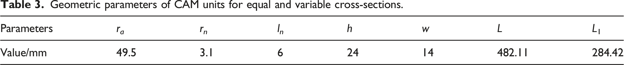
According to the geometric parameters in Table 3, the zero-pole distribution and sound absorption coefficients of the large CAM unit with an inner diameter of 49.5 mm are shown in Figure 5(a) and Figure 5(b). Large sample of CAM unit. (a) Zero-pole distribution diagram; (b) sound absorption coefficient of CAM unit.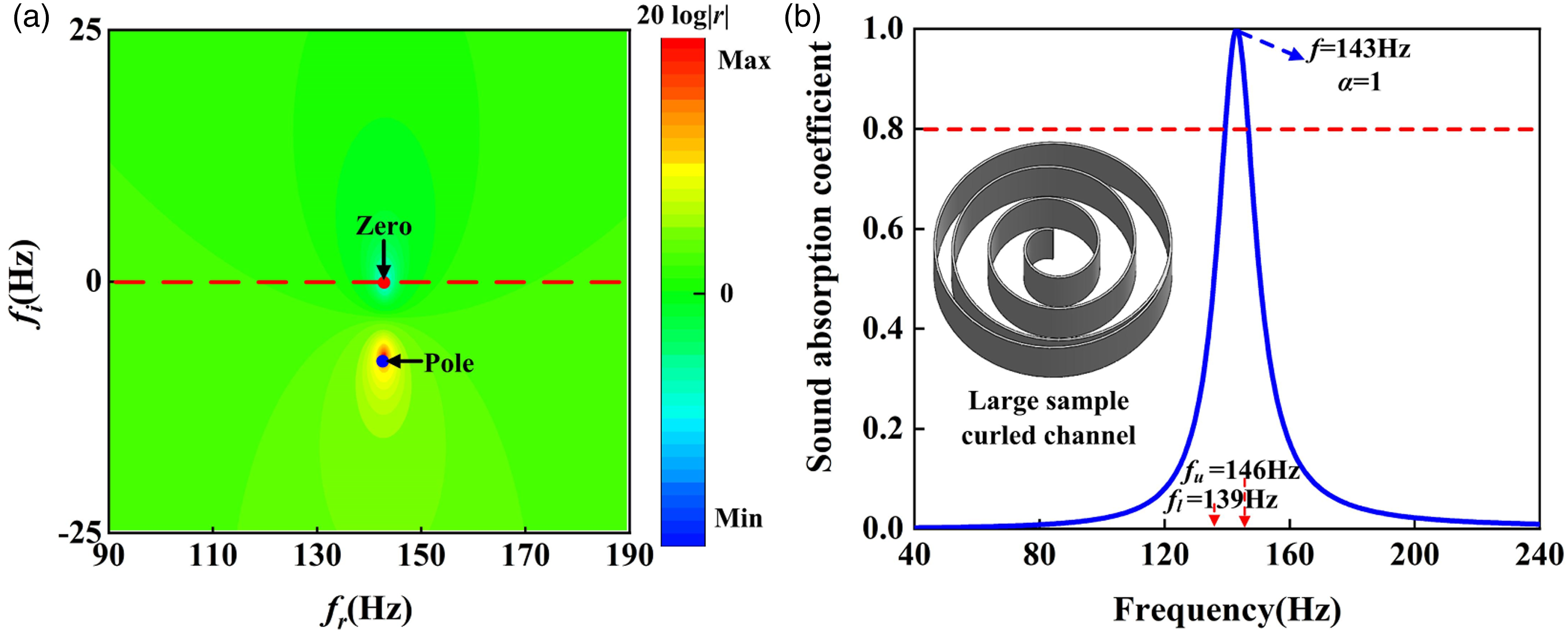
From Figure 5(a), it can be seen that the zero point of the logarithmic reflection coefficient of the CAM unit in Table 3 is located on the real frequency axis, corresponding frequency is 143 Hz. This indicates that the CAM is in a critical loss state, achieving perfect sound absorption at 143 Hz. The illustration in Figure 5(b) shows the curled channel of the CAM unit. From the sound absorption coefficient curve, it can be seen that the CAM unit has achieved perfect sound absorption at 143 Hz. At the same time, the lower limit frequency for the sound absorption coefficient above 0.8 is 139 Hz, the upper limit frequency is 146 Hz, and the bandwidth is 7 Hz. This indicates that in order to achieve low-frequency and broadband perfect sound absorption not only require a large number of CAM units, also require that the two-dimensional plane space of a single unit along the xy direction is large enough.
Experimental verification of curled acoustic metasurface units
To further validate the theoretical model, a large sample of the CAM unit obtained using 3D printing technology based on the geometric parameters in Table 3 is shown in Figure 6(a). Using an acoustic impedance tube with an inner diameter of 99 mm from B&K Denmark, the absorption coefficient of CAM sample is obtained based on the transfer function method. The experimental testing system and platform are shown in Figure 6(b). The sound absorption coefficients obtained from the theoretical and experimental results of the CAM unit are shown in Figure 6(c), the experimental testing site is shown in Figure 6(d). Experimental results of a CAM large sample (a) 3D printed CAM sample; (b) impedance tube sound absorption coefficient testing system; (c) theoretical and experimental results of sound absorption coefficients for the CAM large sample; (d) sound absorption coefficient testing platform and testing site.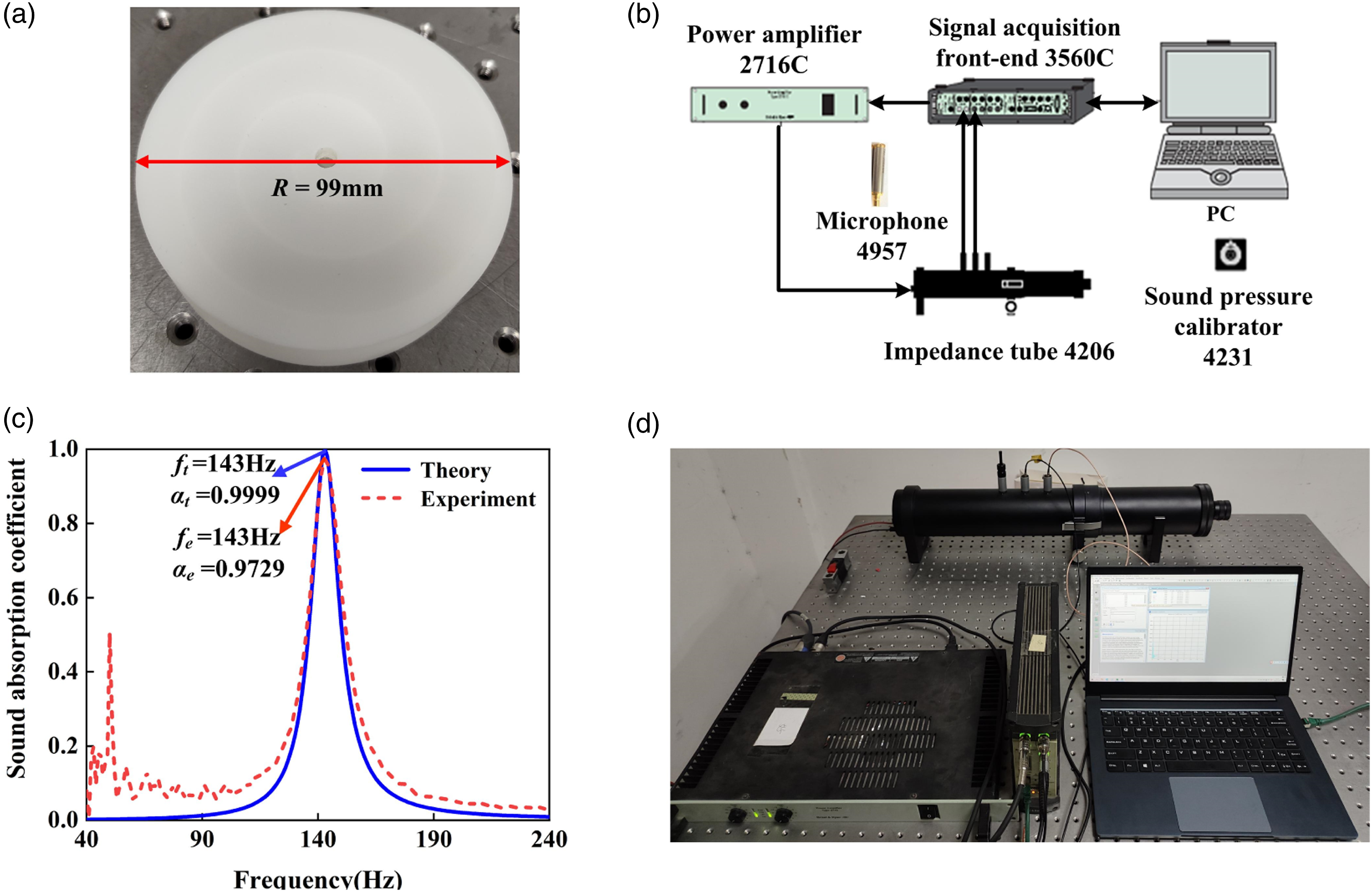
From Figure 6(c), it can be seen that the theoretical model and experimental results of the sound absorption coefficient are in good agreement at the sound absorption peak and corresponding frequency. However, on the sound absorption coefficients on both sides of the peak sound absorption frequency, the experimentally tested sound absorption coefficient is better than the theoretical model calculation results. This is because the 3D printing material uses epoxy resin, which is constrained by the material and geometric wall thickness, making it difficult to meet the completely ideal fully rigid boundary. The small deviation on the peak of the sound absorption coefficient is an error caused by printing accuracy. The consistency between theoretical and experimental results proves the accuracy of the theoretical model.
Theoretical design of low-frequency broadband curled acoustic metasurface
Geometric parameters of four CAM units.
Based on the geometric parameters in Table 4, the complex frequency plane method and theoretical models are used to obtain the zero-pole plots and sound absorption coefficients of four CAM, as shown in Figure 7(a)–(h). Zero-pole diagram and sound absorption coefficients of CAM units (a) zero-pole distribution of unit 1; (b) sound absorption coefficient of unit 1; (c) zero-pole distribution of unit 2; (d) sound absorption coefficient of unit 2; (e) zero-pole distribution of unit 3; (f) sound absorption coefficient of unit 3; (g) zero-pole distribution of unit 4; (h) Sound absorption coefficient of unit 4.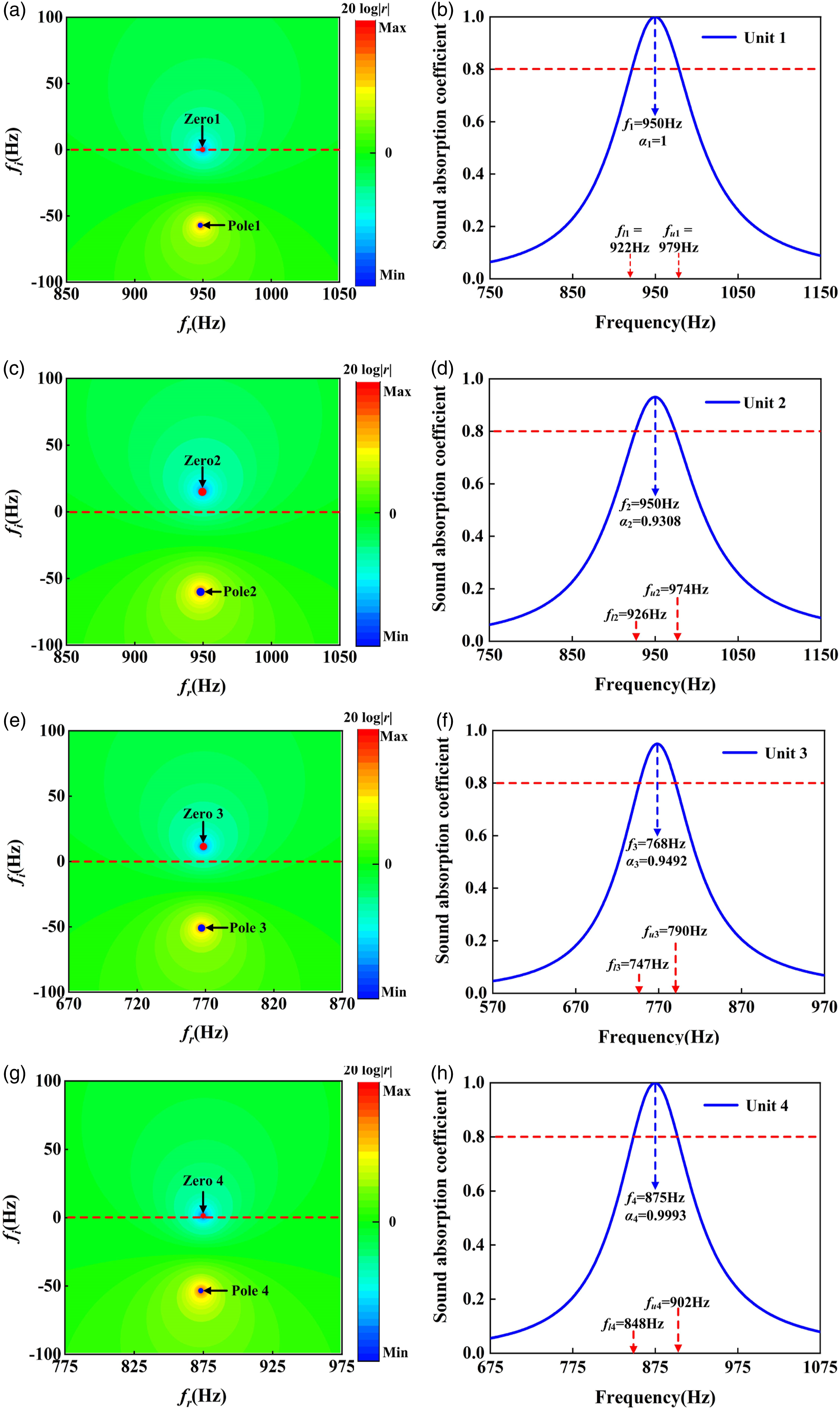
From Figure 7(a), it can be seen that the zero point of unit 1 is located on the real frequency axis, corresponding frequency is 950 Hz. This indicates that unit 1 is in a critical coupled state at a frequency of 950 Hz, and achieving perfect sound absorption. The sound absorption coefficient of unit 1 in Figure 7(b) verifies this point. From the figure, it can be seen that unit 1 has a sound absorption coefficient of 1 at 950 Hz, and the efficient sound absorption frequency band with a sound absorption coefficient above 0.8 is 922 Hz–979 Hz, efficient sound absorption bandwidth is 57 Hz. Similarly, from Figure 7(c), it can be seen that the absorption peak of unit 2 is at 950 Hz, but the zero point is located in the positive plane of the complex frequency plane. Unit 2 is in an under-resistance state and does not achieve perfect absorption. Figure 7(d) shows that unit 2 reaches its peak absorption coefficient at 950 Hz, with an absorption peak of 0.9308. At the same time, the efficient absorption frequency band of unit 2 is 926 Hz–974 Hz and the bandwidth is 48 Hz.
From Figure 7(e), it can be seen that unit 3 is still in an under-resistance state, and the absorption peak appears at 768 Hz. Figure 7(f) shows that the peak absorption coefficient is 0.9492, and the efficient absorption frequency band above 0.8 is 747 Hz–790 Hz, with an efficient absorption bandwidth of 43 Hz. In Figure 7(g), the zero point of unit 4 is very close to the real frequency axis, indicating that unit 4 is infinitely close to perfect sound absorption. From Figure 7(h), it can be seen that unit 4 achieved a sound absorption coefficient of 0.9993 at 875 Hz, and the efficient sound absorption frequency band above 0.8 is 848 Hz–902 Hz, with a bandwidth of 54 Hz.
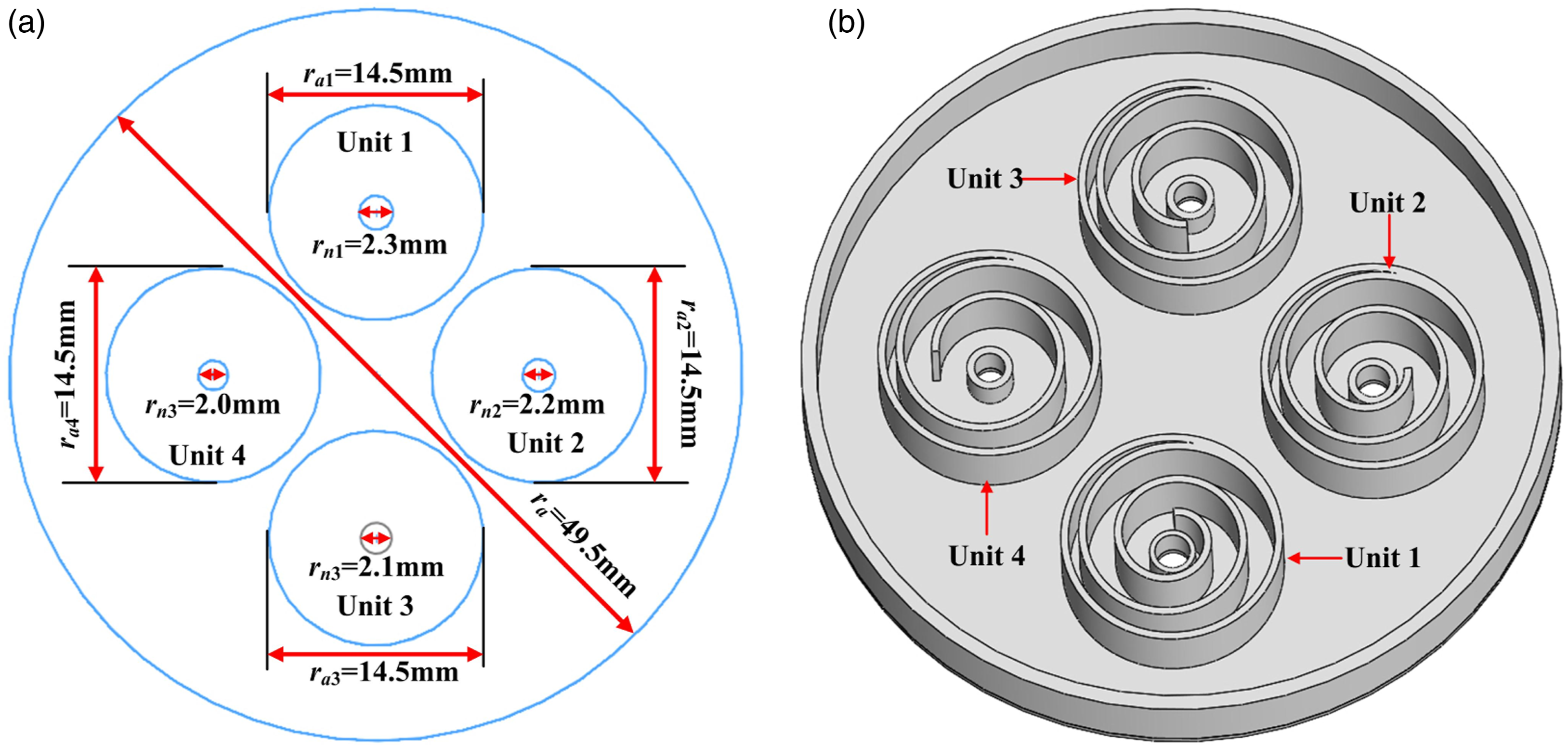
In order to further achieve low-frequency broadband sound absorption, this paper proposed an ultra-thin composite CAM composed of four discrete CAM units in a coplanar manner. To facilitate the experimental verification of a 99 mm impedance tube, the four CAM units in Figure 7 are used as the basic units. The coplanar broadband composite CAM is shown in Figure 8(a), and the actual structure is shown in Figure 8(b). When these CAM units are combined in parallel, the normalized total acoustic impedance of broadband ultra-thin CAM can be expressed as Schematic diagram of broadband ultra-thin CAM (a) coplanar metasurface; (b) coplanar metasurface structure diagram.
Therefore, the reflection and absorption coefficients of the broadband composite CAM can be obtained as follows:
Assuming that when these four CAM units are connected in parallel, they are decoupled (i.e., without considering the increase in equivalent acoustic impedance caused by radius changes), then combining equations (15) and (16) can obtain the zero-pole and sound absorption coefficients of the composite decoupled CAM by the four CAM units in Table 4, as shown in Figure 9(a) and (b). If the equivalent acoustic impedance correction caused by the increase in radius during multi-unit composite is considered, the zero-pole and absorption coefficients of the coupled composite CAM are shown in Figure 9(c) and (d). Zero-pole distributions and theoretical sound absorption coefficients of decoupled and coupled broadband composite CAM.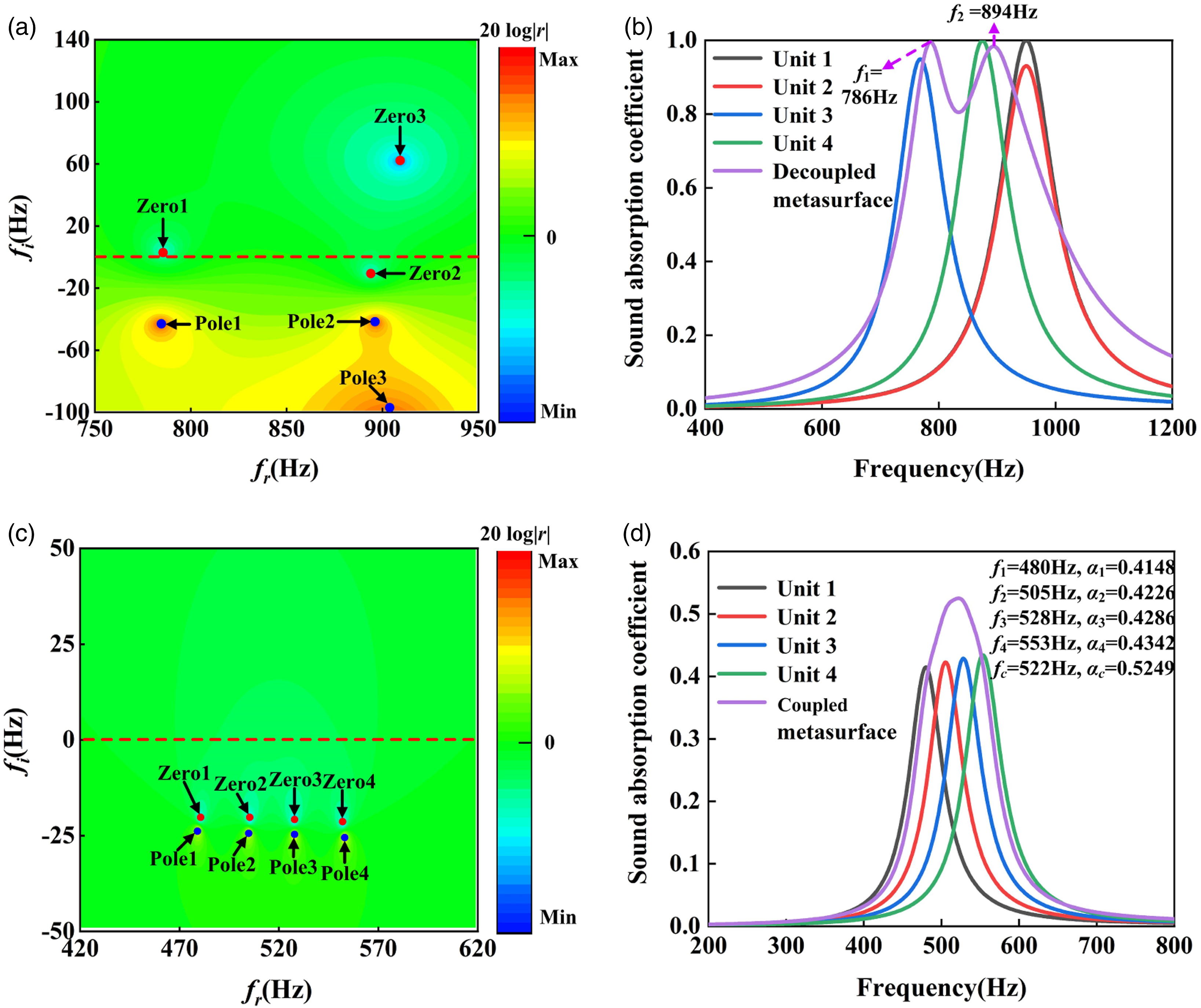
From Figure 9(a), it can be seen that when four units in different states are to be combined in parallel to form a broadband CAM, if the change in the geometric radius during parallel recombination is not considered, there are three zero-pole pairs on the composite CAM, because the absorption peak of units 1 and 2 correspond to the same frequency. Among them, zeros 1 and 2 are very close to the real frequency axis, indicating that the corresponding frequencies are close to perfect sound absorption, while zero 3 deviate far from the real frequency axis and are in an under-resistance state. Figure 9(b) shows the sound absorption coefficient of the decoupled composite CAM. It can be seen that quasi-perfect sound absorption close to 1 are achieved at frequencies of 786 Hz and 894 Hz, respectively. This corresponds to the zeros 1 and 2 in Figure 9(a). From the perspective of the operating frequency, the main contributions to these two absorption peaks are units 3 and 4, while units 1 and 2 are in an under-resistance state after parallel connection due to the same absorption peak.
Figure 9(c) shows the zero-pole distribution when considering the increase in equivalent acoustic impedance caused by the increase in the radius of the multi-unit composite CAM. When the radius increases and a new equivalent acoustic impedance increment is introduced, the composite CAM exhibits four zero-pole pairs, and all zeros are in an over-resistance state. The zero point is away from the real axis of frequency, indicating that the over-resistance state is more severe and the sound absorption coefficient is poor. From Figure 9(d), it can be seen that when considering the increase in acoustic impedance caused by changes in the radius of the composite CAM, units 1–4 are in an over-resistance state. Among them, the absorption peak of unit 1 decreases from 1 to 0.4286, and the corresponding frequency shifts from 950 Hz to 528 Hz. Similarly, the absorption peak of unit 2 decreases from 0.9308 to 0.4342, the corresponding frequency shifts from 950 Hz to 553 Hz, and the absorption peak of unit 3 decreases from 0.9492 to 0.4148, corresponding frequency decreased from 768 Hz to 480 Hz, the absorption peak of unit 4 decreased from 0.9993 to 0.4226, and corresponding frequency decreased from 875 Hz to 505 Hz. Therefore, when these four over-resistance CAM units are combined, although broadband sound absorption can be achieved, their absorption peak has decreased to 0.5249. This is because the radius of composite CAM increases, and due to the constant radius of the embedded holes in the unit, the equivalent sound radiation impedance caused by the variable cross-section increases. Each component unit is in an over-resistance state, resulting in a significant decrease in the sound absorption coefficient. The broadband sound absorption CAM after multi-unit composite is also in an over-resistance state, and the sound absorption coefficient also shows a significant decrease. As a result, it is difficult to achieve broadband and efficient sound absorption on composite broadband CAM with multiple units in parallel.
Experimental verification of composite broadband curled acoustic metasurface
In order to verify the theoretical design of four CAM units and the over-resistance problem of composite broadband CAM after four units are connected in parallel, we prepared four CAM units 1–4 with an inner diameter of 29 mm and a broadband CAM with an inner diameter of 99 mm using 3D printing technology based on the geometric parameters in Table 4. The testing systems for small and large samples are shown in Figure 10(a) and (b), respectively. The theoretical and experimental absorption coefficients of units 1–4 with an inner diameter of 29 mm are shown in Figure 10(c)–(f). The theoretical and experimental sound absorption coefficients of the coupled composite CAM with an inner diameter of 99 mm are shown in Figure 10(g). In order to ensure the decoupled condition of various units for the composite CAM, a frame is added to the surface of the composite CAM as a control method, and the theoretical under ideal decoupled condition and experimental sound absorption coefficients of the composite CAM with a frame are shown in Figure 10(h). Experimental verification of the sound absorption coefficient for CAM. (a) An impedance tube testing system for measuring the sound absorption coefficient of CAM units with an inner diameter of 29 mm; (b) impedance tube testing system for composite CAM absorption coefficient with an inner diameter of 99 mm; (c) theoretical and experimental sound absorption coefficient of unit 1; (d) theoretical and experimental sound absorption coefficient of unit 2; (e) theoretical and experimental sound absorption coefficient of unit 3; (f) theoretical and experimental sound absorption coefficient of unit 4; (g) theoretical and experimental sound absorption coefficients of coupled composite broadband CAM; (h) theoretical and experimental sound absorption coefficients of decoupled composite broadband CAM.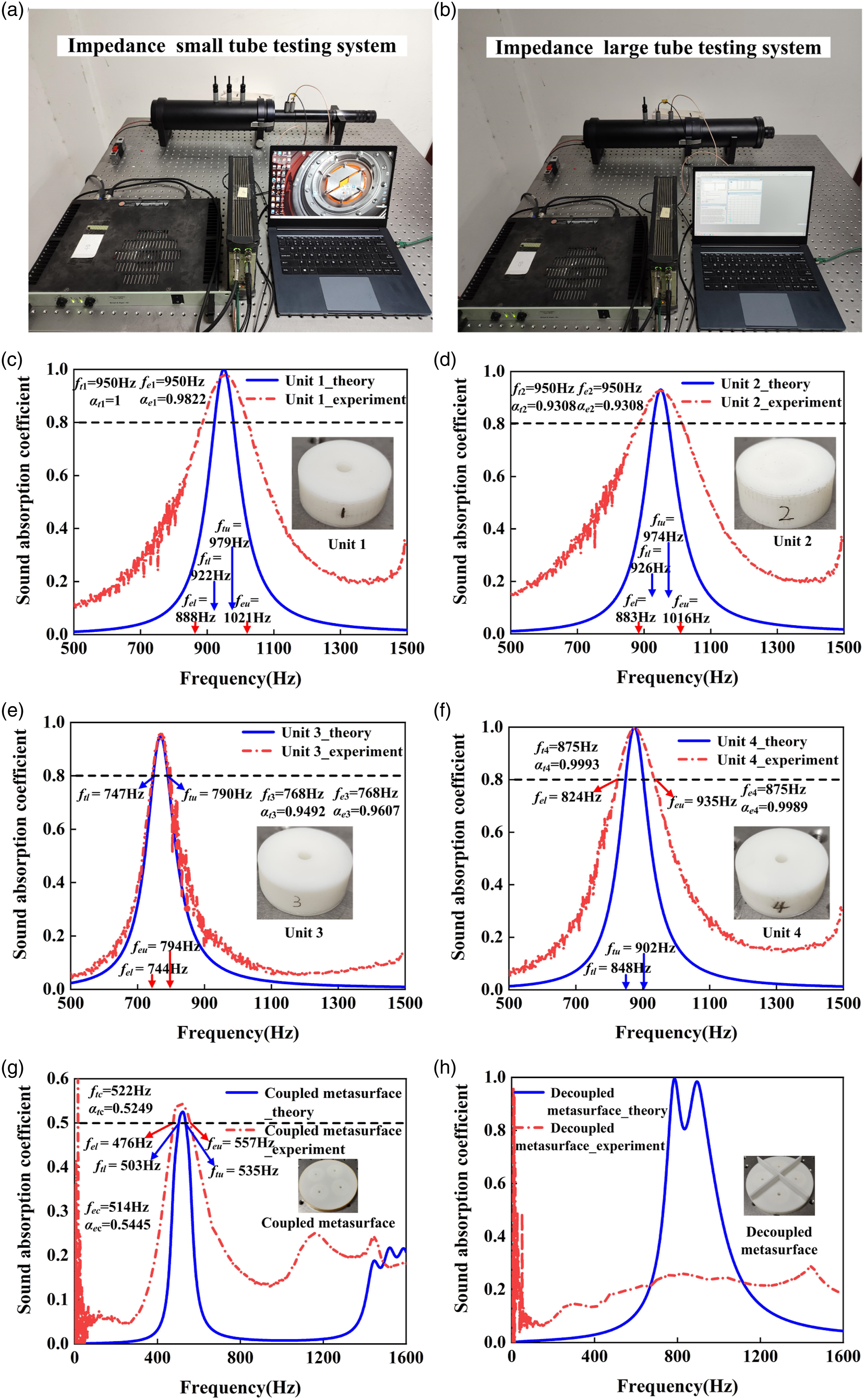
Figure 10(c) shows the theoretical and experimental sound absorption coefficients of the CAM unit 1, and the illustration shows the experimental sample of unit 1 prepared by 3D printing technology. The theoretical absorption peak of unit 1 is 1, corresponding frequency is 950 Hz. The efficient absorption frequency band with absorption coefficient above 0.8 is 888 Hz–1021 Hz, while the experimental absorption peak of unit 1 is 0.9822, corresponding frequency is 950 Hz. The efficient absorption frequency band with absorption coefficient above 0.8 is 922 Hz–979 Hz. From the absorption peak and corresponding frequency, the theoretical and experimental results are basically consistent, but for the efficient absorption bandwidth with absorption coefficient above 0.8, the bandwidth of experimental testing is higher than the theoretical model calculation results. This is because in the process of solving the sound absorption coefficient in the theoretical model, the boundary condition used is a rigid non-transmission boundary. However, when using 3D printing technology to process the sample, the matrix material is resin, which means there is a small amount of leakage sound. Therefore, it appears in the frequency band outside the corresponding frequency of the absorption peak. The experimental sound absorption coefficient is better than the theoretical model calculation results. Similarly, from Figure 10(d), the theoretical absorption peak of unit 2 is 0.9308, corresponding frequency is 950 Hz, while the experimental absorption peak is 0.9308, corresponding frequency is 950 Hz. The theoretical and experimental absorption peaks and corresponding frequencies are completely consistent, but the theoretical efficiency absorption frequency band of unit 2 is 926 Hz–974 Hz, which is lower than the experimental efficiency absorption frequency band of 883 Hz–1016 Hz. This phenomenon further validates the deviation of theoretical and experimental absorption coefficients beyond the absorption peak caused by the ideal conditions of the theoretical model. As the design of curled broadband CAM mainly considers the perfect absorption frequency band, the deviation beyond the absorption peak can be ignored.
Figure 10(e) shows the sound absorption coefficient of unit 3 for theoretical and experimental results. The theoretical model calculates a sound absorption peak of 0.9492, corresponding frequency is 768 Hz. The experimental test results show that unit 3 achieved an absorption peak of 0.9607 at 768 Hz. At this time, the theoretical efficient sound absorption frequency band is 747 Hz–790 Hz, and the experimental efficient sound absorption frequency band is 744 Hz–794 Hz. The theoretical and experimental efficient sound absorption bandwidth of unit 3 is also very close. This is because unit 3 has a relatively thick wall thickness due to changes in the length of the curled channel, which is closer to the hard sound field boundary conditions in the theoretical model. Figure 10(f) shows the theoretical and experimental absorption coefficients of unit 4. The theoretical absorption peak of unit 4 is 0.9993, which appears at 875 Hz, while the experimental absorption peak is 0.9989, which also appears at 875 Hz. The theoretical and experimental absorption peak frequencies are basically the same. Similarly, due to the ideality of boundary conditions, the theoretical efficient absorption frequency band of unit 4 is 848 Hz–902 Hz, which is lower than the experimental, 824 Hz–935 Hz. Overall, the experimental test results of units 1–4 verified the accuracy and reliability of the theoretical model.
In Figure 10(g), the theoretical and experimental sound absorption coefficients of the coupled broadband composite CAM are presented, which are composed of units 1–4 and take into account the increase in composite radius and the introduction of impedance increment. The radius of the multi-unit composite CAM increases, while the embedded aperture of each unit remains unchanged. The equivalent acoustic radiation impedance of the mutation interface increases, and the composite units are in an over-resistance state. Therefore, although the multi-unit parallel connection method can achieve broadband sound absorption, its sound absorption coefficient will decrease. From Figure 10(g), after four nearly perfect sound absorbing units are connected in parallel, their theoretical absorption peak is 0.5249, corresponding frequency is 522 Hz. This indicates that the increase in sound resistance causes the structure to be in an over-resistance state, resulting in a lower sound absorption coefficient, while the increase in sound impedance causes the sound absorption frequency to shift to a lower frequency. Similarly, the absorption peak of the experimentally tested composite CAM is 0.5445, corresponding frequency is 514 Hz. The absorption peak and corresponding frequency of the theoretically and experimentally tested coupled composite CAM are basically the same. However, due to the previous research finding that the theoretical efficient sound absorption broadbands of CAM units are lower than the experimental results, after combining multiple units to form a broadband CAM, the experimental result shows that the sound absorption coefficient above 0.5 is still higher than the theoretical results in terms of sound absorption bandwidth.
In order to solve the problem of equivalent acoustic impedance increase caused by the increase of composite radius, this paper uses 3D printing technology to form a resin-based isolation frame on the surface for the composite CAM, as shown in the illustration in Figure 10(h). The red curve in the figure is experimental absorption coefficient of the composite CAM that attempts to achieve unit decoupled condition using a frame structure. The blue curve is the theoretical absorption coefficient of the ideal decoupled composite CAM. From the figure, it is not feasible to use an additional structure to achieve decoupled condition between each unit and thus achieve broadband absorption. Because after using frame separation, the sound absorption of the experimental result indicates that the composite CAM is still in a severe over-resistance state and has not achieved broadband efficient sound absorption. This provides a reference for future research work on offsetting unit over-resistance problems by adjusting the geometric parameters of the unit and the degree of freedom of the composite CAM.
Discussion and conclusion
In this paper, the THR was taken as the research object, and a simplified model for calculating the absorption coefficient of THR was established. Furthermore, the influence of geometric parameters on the sound absorption performance of THR unit was analyzed. In order to achieve low-frequency sound absorption structures, a CAM with deep subwavelength characteristics composed of embedded holes and curled channels was proposed. Based on the complex frequency plane method, four discrete CAM units with a thickness of only 12 mm and sound absorption coefficients above 0.9 in the 768 Hz–950 Hz frequency range were designed. A composite broadband deep subwavelength acoustic metasurface was studied, which was paralleled by four discrete units. The acoustic performance of the composite CAM under decoupled and coupled conditions was theoretically calculated, achieving efficient sound absorption above 0.8 in the 758 Hz–940 Hz frequency range under decoupled conditions. Furthermore, the sound absorption of the composite CAM under decoupled and coupled conditions was experimentally verified. This study has certain guiding significance for the design of multi-unit composite acoustic metasurfaces, and provides theoretical and practical reference value for multi-degree of freedom low-frequency broadband noise control technology.
Footnotes
Author contributions
Baozhu Cheng: Conceptualization, methodology, simulation, investigation. Jiesen Zhang: writing of the original manuscript, visualization; Jiaqi Sun: Software, validation, manuscript revision; Yang Liu: Writing - review & editing, funding acquisition; Bin Li and Hong Hou: Supervision, funding acquisition.
Declaration of conflicting interests
The author(s) declared no potential conflicts of interest with respect to the research, authorship, and/or publication of this article.
Funding
The author(s) disclosed receipt of the following financial support for the research, authorship, and/or publication of this article: This work was supported by the National Natural Science Foundation of China (Grant Nos. 12174314, 12204201).
Data Availability Statement
The datasets used and/or analyzed during the current study are available from the corresponding author upon reasonable request.