
Abstract
The impedance matching is essential in producing high-intensity acoustic waves. This paper studies the impedance calculation methods of modulators and double-chamber Helmholtz resonators based on fluid mechanics, aeroacoustics, and electro-acoustic analogy principles. The results: ① The impedance expression of the resonators is derived. ② The impedance variation law of the chamber volume, the stator size, the air supply pressure, the air supply flow, and the working frequency is calculated. ③ The impedance-matching design scheme of the two-chamber Helmholtz low frequency and high acoustic intensity generator is given. Based on the experimental results of the high acoustic intensity generating device that the author has manufactured in the closed space, the correctness of the impedance calculation and matching design scheme in this paper is verified. This method has guiding significance for the design of high-intensity acoustic generating devices in confined space.
Introduction
Airflow modulation acoustic generators, 1 called airflow modulators, have high acoustic generation efficiency and intensity. The airflow loudspeaker can reach an acoustic power of 10 thousand watts. The low-frequency aerodynamic high-intensity acoustic source is a kind of airflow-modulated acoustic wave generator. Low-frequency aerodynamic high-intensity acoustic sources can be used for boiler ash removal, 2 airport bird repelling, 3 biological effect experiments, 4 etc.
Most theoretical studies on aerodynamic sound generation are theoretical calculations of aerodynamic noise in open space. It is mainly used for the acoustic generation of the aerodynamic loudspeakers, wings, rotors, and other structures in the fluid sound 5 or high-pressure jet. 6 In the 1960s and 1970s, Meyer 7 studied the acoustic principle of modulators. Yang et al. 8 simulated the acoustic source region of the helicopter rotor High-Speed Impulsive (HSI) noise by solving Navier–Stokes equations, and the acoustic near-field is simulated by solving the Linearized Euler Equations (LEE) based on the Runge–Kutta Discontinuous Galerkin (RKDG) method. Yangzhou et al. 9 derived the on-surface source terms of the aeroacoustic sources of a two-bladed propeller emanating the far-field noise based on the Ffowcs Williams and Hawking’s equation for low Mach number flows and constant rotating propellers. Zhang et al. 10 conducted a noise reduction study of an airfoil with a bioinspired ridge-like structure. They take the K-Epsilon model to capture the stable flow field, and the large eddy simulation (LES) model is used for the turbulence transient simulation with the initial value of the steady flow field. Shao et al. 11 calculated the noise signal of the jet noise characteristics of the fighter’s double S-bend nozzles at the far-field monitoring points with the Ffowcs Williams–Hawkings (FW–H) method. Then, the sound source characteristics of the double S-bend nozzle are analyzed. To dissipate noise generated by thermoacoustic instabilities, Zhao et al. 12 conducted some perforated liners with different porosities by experimental and numerical investigations. Zhao et al. 13 evaluated the aeroacoustics damping performance of an in-duct perforated orifice with a bias flow regarding acoustic power absorption and reflection coefficients. Zhao et al. 14 studied the aeroacoustics damping performances of 11 in-duct perforated plates in a cold-flow pipe with a variable Mach number by experiment. Mu et al. 15 investigated the near-field and far-field noise pressure levels and directivity of the two nozzles using the Lighthill equation excited by a quadrupole under fluid input. Zhao et al. 16 studied the dynamic flame–acoustics–heater interaction by numerical simulation.
In the 19th century, the German scientist Helmholtz invented the “Helmholtz resonator” to study resonance problems. The Helmholtz resonator is a vibroacoustic system with specific practical applications in production and life. However, few pieces of literature have been on its related application research in recent decades. The following are several major relevant literatures. Zhao et al. 17 studied the application of Helmholtz resonators in acoustic dampers to stabilize unstable combustion systems. Zhao and Li 18 developed a feedback control strategy for mitigating combustion instabilities using a Helmholtz resonator with an oscillating volume. Guan et al. 19 studied the acoustic damping performances of double-layer in-duct perforated plates at low Mach (Ma) and Helmholtz number (He). By experimental and theoretical studies, Guan et al. 20 evaluated aeroacoustics damping performances of off-axial double-layer in-duct orifices at low Mach and Helmholtz numbers. Panton 21 conducted a comparative study on the influence of various nozzle shapes of the resonator on the resonance response. Dequand et al. 22 studied the throat characteristics of Helmholtz resonators driven by reciprocating pistons. Dequand et al. 22 considered self-sustained oscillations of the grazing flow along the neck of a Helmholtz-like resonator and carried the numerical simulations based on the Euler equations for inviscid and two-dimensional compressible flows. 23 Jungowski and Grabitz 24 studied the oscillation mechanism of the Helmholtz resonator by experimental and numerical investigations. Liu et al. 25 investigated the turbulent flow past a 120°-impinging edge Helmholtz nozzle. They proposed a modified theoretical model to obtain the oscillation frequency range. Guan et al. 26 presented a modified design of a Helmholtz resonator and evaluated the effect of implementing a rigid baffle in its cavity. Boesch et al. 27 constructed a high-intensity infrasound generation device using an airflow modulator and a Helmholtz resonator. The single-chamber resonator system does not consider the impedance matching between the modulator and the resonator, and the generated acoustic intensity is only greater than 140 dB. The double-chamber resonator system considers the impedance matching between the modulator and the resonator and achieves an acoustic intensity greater than 155 dB. 28 The author of this paper, Ming-Rong et al. 29 used the approximate theory to investigate the maximum sound pressure level, sound power, and airflow efficiency of this airflow modulator. The working mechanisms of the infrasonic acoustic generator consisting of a modulator and a Helmholtz resonator were studied by FLUENT numerical simulations. Although the above work gives the impedance data of the modulator and the resonator, and also uses the electro-acoustic analogy to calculate the resonator impedance, it does not give a specific calculation method of the resonator impedance, nor does it give the change rule of the impedance when the main parameters change.
Combining the airflow modulator and the Helmholtz resonator can produce high-intensity, low-frequency acoustic waves in the resonator. According to the principle of acoustic radiation, in the process of acoustic wave propagation, if the impedance does not match, the acoustic wave will be reflected, resulting in the loss of acoustic energy in propagation. So far, the theoretical research of aeroacoustics technology has rarely involved impedance calculation. It may be because the acoustic wave radiated into the air is more about the impedance matching between the radiator, such as the horn, and the air. The modulator impedance only needs a smooth transition with the horn impedance. Usually, it can be achieved by ensuring that the inner wall connection between the modulator outlet and the horn inlet is smooth and continuous. However, to generate high-intensity acoustic waves in a closed space with a modulator, the impedance matching between the modulator and the closed space is essential, and the impedance calculation and matching scheme design are much more complicated.
In this paper, the calculation method of the impedance of the airflow modulator is studied, and the impedance variation law when the main parameters change is calculated. Based on the electro-acoustic analogy, the impedance calculation formula of the two-chamber Helmholtz resonator is derived. The impedance variation law is when the absorption coefficient and volume change are studied, and an impedance-matching design scheme of a high-intensity low-frequency generator in a closed space is given.
Impedance calculation of high-intensity acoustic generator in enclosed space
System overview
The whole system of the low-frequency and high-intensity acoustic generator in the closed space studied in this paper mainly includes the air compressor, the modulator part, and the resonator part (Figure 1). The air compressor is used as the air source, and the compressed air is supplied to the airflow modulator after entering the air chamber. The acoustic wave generated by the modulator enters the resonators connected to the ambient air by an exhaust pipe. The exhaust pipe is also the resonance tube that causes resonance. The resonator is designed based on the Helmholtz principle. The double resonator structure is adopted, and the two resonators are connected through the resonance tube. The purpose of this device is to generate high-intensity acoustic waves in the resonator. Therefore, whether the impedance of the modulator outlet matches the impedance of the resonators is related to the intensity and efficiency of the generated acoustic wave. Schematic diagram of the system composition.
Impedance calculation method of the modulator
To calculate the impedance of the modulator, the working principle of the modulator and its exhaust area must be understood. Figure 2 shows the schematic diagram of the internal structure of the modulator. The inner cylinder is the stator, and the outer cylinder is the rotor. The inner cylinder is connected to the air chamber through the pipeline, and the outer cylinder rotates at a specific frequency under the drive of the servo motor. When the square holes on the outer cylinder and the square holes on the inner cylinder intersect, it will exhaust. The jet generated by the periodic exhaust generates a specific frequency of acoustic waves, which propagates outward from the outlet of the modulator after convergence. It may be said that the fundamental frequency of the acoustic wave is the working frequency. The axial length of the square hole on the setter and the rotor is L. Ignoring the wall thickness, the radius of the stator and rotor can be set to r. Suppose the same exhaust area is divided into several nozzles evenly distributed on the circumference. In that case, it is convenient for mechanical processing and is also conducive to the stability of the modulator operation. There are n square holes with arc length Schematic diagram of the modulator.

It can be deduced that the exhaust area of a single cycle as
The fluid Mach number can be derived from the fundamental equations of thermodynamics

The local sound velocity of the fluid can also be derived as
From the ideal gas law, it can be derived as

Thus, the mass flow changing with time through the modulator nozzle can be obtained as

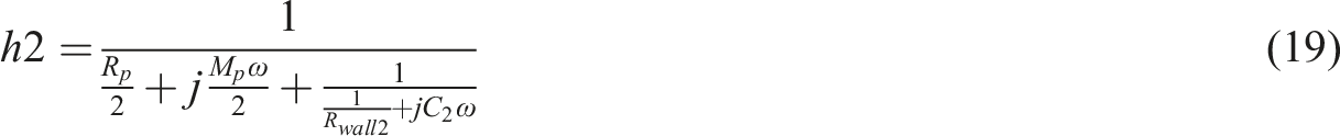
Comprehensive formulas (3)–(6) can be reduced to

Then, the mass flow of the nozzle can be converted into the volume flow

According to the principle of fluid mechanics, the pressure of the air chamber changing with time can be deduced

Similarly, the time-varying temperature in the air chamber can be given as

When the modulator works at a single frequency, the impedance changes periodically according to the working frequency, and the impedance in a cycle also changes. Using the definition of the modulator impedance in Ref. 28 : in a cycle, find out the maximum flow value and then find out the corresponding pressure. Pressure divided by flow is the impedance of the modulator. The impedance matching is considered when the flow is the largest modulator impedance.
Impedance calculation of the resonator based on electro-acoustic analogy
The electro-acoustic analogy has been widely used in the design of acoustic devices such as loudspeakers. It can transform complex acoustic problems into electrical problems and facilitate the analysis of the relationship between various parameters. The equivalent circuit of the Helmholtz resonator part of the system shown in Figure 1 is shown in Figure 3. Assume that the resonator wall is rigid and satisfies that the linearity of the resonator is much smaller than the acoustic wavelength. Equivalent circuit of the double-chamber resonator.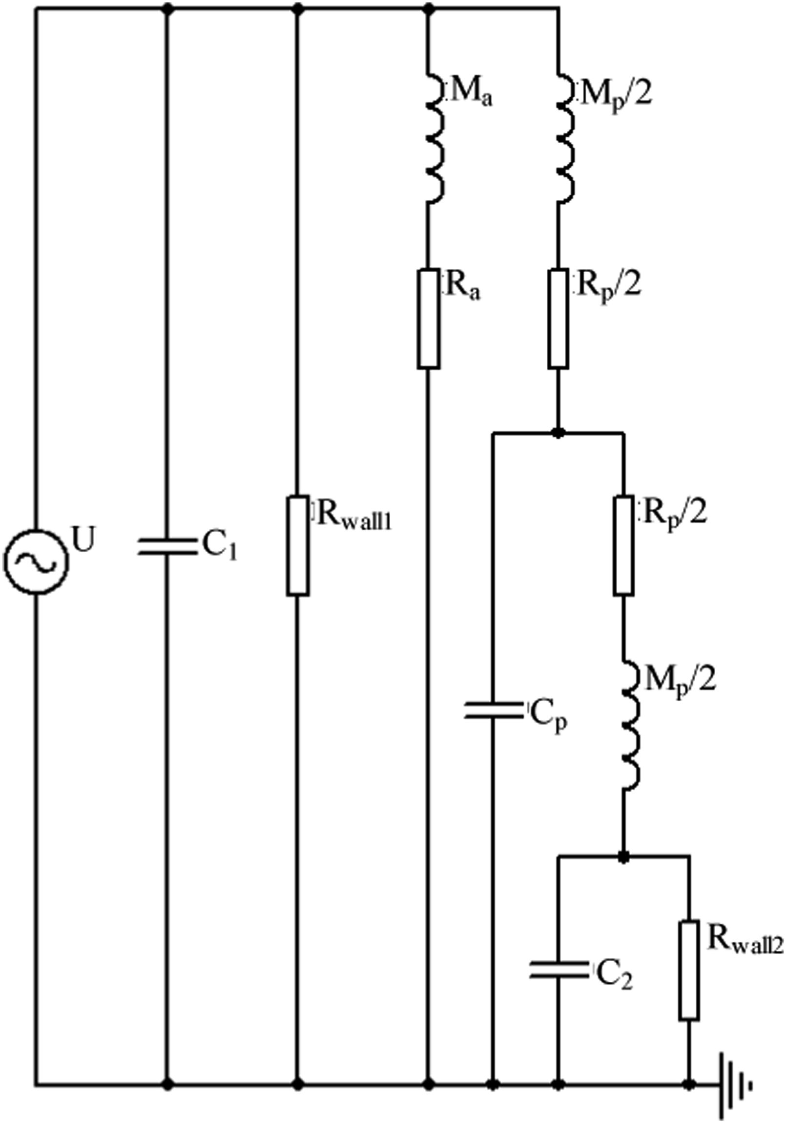
When the resonator operates, the internal air will compress and expand, which can be analogized to capacitance

The air column inside the resonance tube is similar to the “piston” of reciprocating motion, which can be analogous to the inductance

The influence of wall surface and air friction can be analogized to resistance

The acoustic resistance caused by the kinematic viscosity of the fluid in the resonance tube is

The acoustic resistance caused by the dynamic viscosity of the fluid in the resonance tube is

Thus, the total resistance of the fluid in the resonance tube is

Let the inductance of the resonance tube


Application in the design of the high-intensity acoustic generator
Impedance calculation of the modulator
The basic design parameters of the modulator are as follows: the radius of the stator and the rotor tube is 0.14 m, the axial length of the square hole on the stator and the rotor tube is 0.3 m, the width of the square hole on the stator tube is 0.075 m, and the width of the square hole on the rotor tube is 0.075 m. The number of nozzle groups is 2. The air source parameters are air supply pressure 130 kPa and air supply flow 1 m3/s. The chamber volume is 0.25 m3.
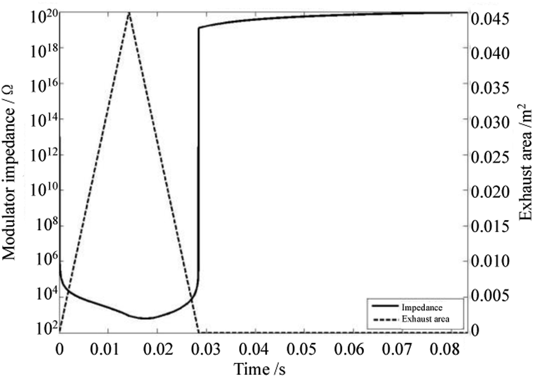
If the working frequency is 12 Hz, the exhaust area, chamber pressure, and nozzle flow can be calculated as shown in Figure 4. It can be seen that the pressure, flow, and exhaust area of the air chamber change periodically according to the working frequency. The pressure of the air chamber reaches the maximum at the beginning of the exhaust, and the pressure of the air chamber reaches the minimum before the end of the exhaust process. The nozzle flow reaches the maximum before the exhaust area reaches the maximum. According to the ratio of the nozzle flow at each time to the corresponding chamber pressure value, the single-cycle impedance result shown in Figure 5 can be calculated. It can be seen that the impedance gradually decreases with the increase of the exhaust area, and the impedance is infinite when the nozzle is closed. Due to the effect of the chamber, the impedance is not necessarily the smallest when the exhaust area is the largest. According to the modulator impedance definition, the modulator nozzle’s maximum flow is 3.687 m3/s, and the corresponding air chamber pressure is 8290.4 Pa, so the impedance of the modulator is 2248.3 Ω. Calculation results of the multi-period characteristic parameters of the modulator. Impedance calculation results of the single period.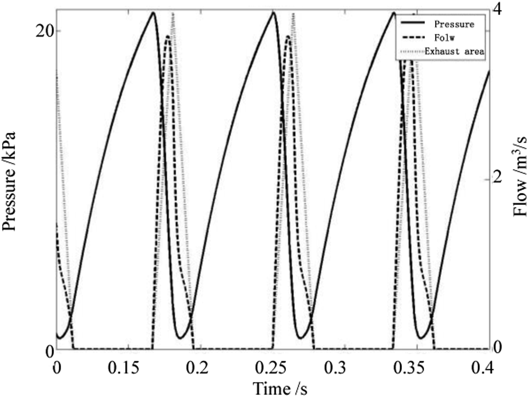
The law of the modulator impedance changing with the main parameters
From the previous theoretical analysis, the main parameters affecting the impedance of the modulator are chamber volume, stator opening size, air supply pressure, air supply flow, and working frequency. The basic parameters of the modulator are the same as the basic parameters of the modulator of this paper. In addition to the working frequency, the working frequency is 12 Hz when calculating the other parameters. The curves of the modulator impedance with these parameters are calculated, respectively. Figures 6–10 are the calculation results. It can be seen that ① Air chamber volume change. Calculate the impedance when the air chamber volume changes in the range of 0.05∼0.5 m3. It can be seen that as the volume of the air chamber increases, the impedance decreases continuously. The impedance is about 4800 Ω at 0.05 m3, and the impedance is about 1500 Ω at 0.5 m3. ② Stator width change. Calculate the impedance when the stator width changes in the range of 0.04∼0.19 m. It can be seen that the larger the stator width is, the smaller the impedance is. When the stator width is greater than 0.06 m, the impedance of the modulator is less than 2300 Ω, and the impedance decreases slowly. The impedance reduction rate is larger when the stator width is less than 0.06 m. ③ Air supply pressure change. Calculate the impedance when the air supply pressure changes in the range of 110∼500 kPa. It can be seen that the greater the supply pressure, the greater the impedance, and the impedance of the modulator is less than 2400 Ω when the supply pressure is less than 150 kPa. When the air supply pressure is greater than 150 kPa, with the increase of pressure, the impedance increase rate decreases, and the curve tends to be gentle. ④ The change of air supply flow. Calculate the impedance of the air supply flow in the range of 0.03∼1.6 m3/s. It can be seen that the larger the volume flow rate is, the larger the impedance is. When the volume flow rate is 0.4∼1.6 m3/s, the impedance of the modulator is greater than 2000 Ω, and the impedance increases slowly. ⑤ Working frequency change. Calculate the impedance when the working frequency changes in the range of 1∼25 Hz. It can be seen that the impedance decreases with the increase in working frequency. The impedance is about 6400 Ω at 1 Hz and 1500 Ω at 25 Hz. The law of impedance changing with the air chamber volume. The law of impedance changing with the stator hole width. The law of impedance changing with the air supply pressure. The law of impedance changing with the air supply flow. The law of impedance changing with working frequency.
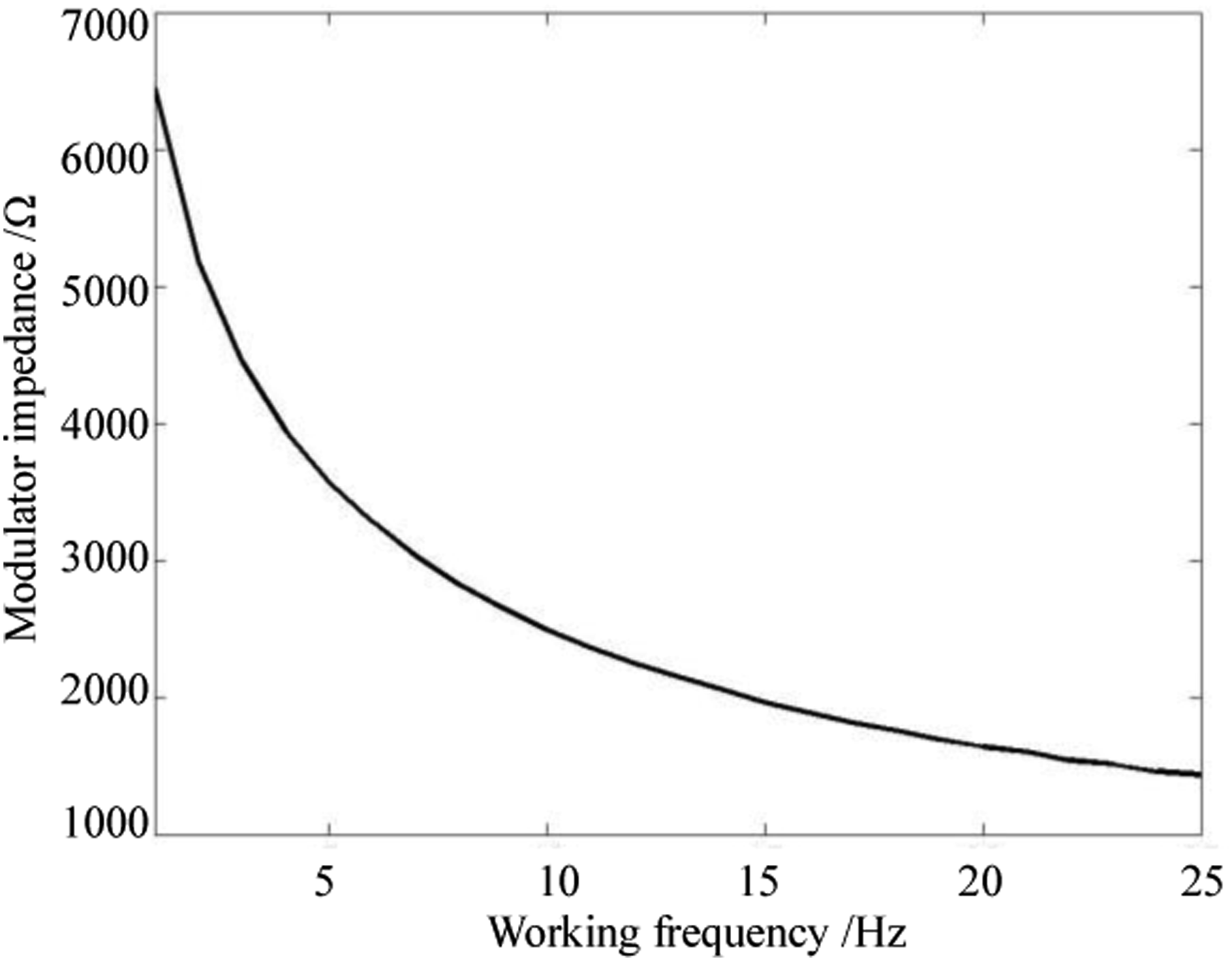
Based on these changes, it can be seen that increasing the volume of the air chamber, increasing the width of the stator, reducing the air supply pressure, reducing the air supply flow, and increasing the working frequency can reduce the impedance of the modulator.
Impedance calculation of the resonator
The two chambers of the double-chamber Helmholtz resonator have the same shape, which is 1.5 m wide, 1.3 m deep, and 1.6 m high, and the total volume is about 6.2 m3. Two resonance tubes with a radius of 0.125 m and a length of 1.4 m are used, and an exhaust pipe with a radius of 0.125 m and a length of 6 m is used.
The resonator has two resonance frequencies. For the convenience of description, the larger value is called the high-end resonance frequency, which is the resonance frequency of the resonance structure composed of the resonance tube inside the resonator and the two resonators. The smaller value is the low-end resonance frequency, which is the resonance frequency of the resonance structure composed of the exhaust pipe and the two resonators.
The inner wall of the resonator is coated with paint on the rigid wall. According to the sound absorption coefficient table of commonly used building materials, the sound absorption coefficient of similar materials at 125 Hz can be found to be 0.01. It can be predicted that the sound absorption coefficient of the inner wall of the resonator is less than 0.01. Still, considering the sound absorption effect of the object in the resonator, the actual sound absorption coefficient of the inner wall of the resonator is estimated to be about 0.01. It is advisable to take 0.013 as the sound absorption coefficient to calculate. Figure 11 shows the calculation results. It can be seen that there are two pronounced resonance peaks in the impedance curve. The low-end resonance frequency is 0.7 Hz, with an impedance of 2454.8 Ω. The high-end resonance frequency is 12.8 Hz, with an impedance of 2335.8 Ω. Impedance curve of the resonator.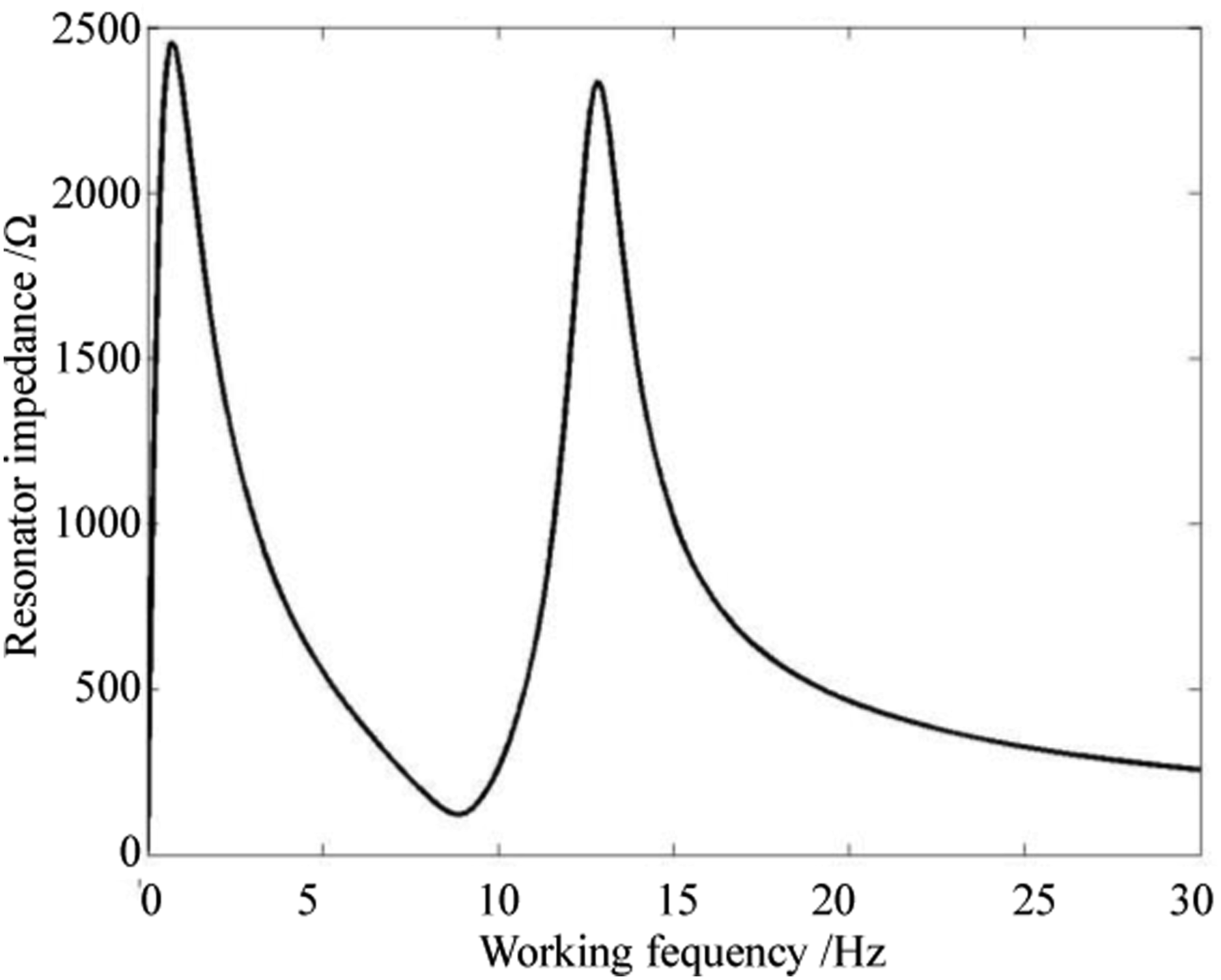
The law of the resonator impedance changing with the main parameters
Similarly, the law of the resonator impedance changing with the sound absorption coefficient of the inner wall of the resonator shown in Figure 12 can be calculated. In Figures 12 and 13, f-high represents the high-end resonance frequency, and f-low represents the low-end resonance frequency. It can be seen from Figure 12 that the size of the two resonance frequencies of the resonator changes regularly with the sound absorption coefficient:① As the sound absorption coefficient increases, the impedance of both resonance frequencies decreases.② When the sound absorption coefficient is less than 0.017, the impedance of the low-end resonance frequency is greater than that of the high-end resonance frequency, and the smaller the sound absorption coefficient, the greater the gap. ③ When the sound absorption coefficient is greater than 0.017, the impedance of the high-end resonance frequency is greater than that of the low-end resonance frequency. The gap is the largest when the sound absorption coefficient is about 0.09 and gradually decreases. The law of the resonator impedance changes with the inner wall’s absorption coefficient. The law of the resonator impedance changing with the volume.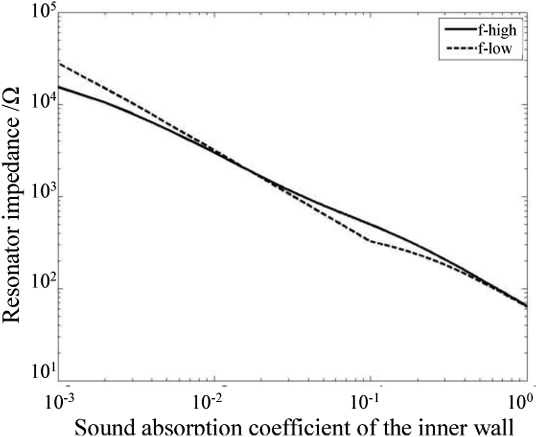
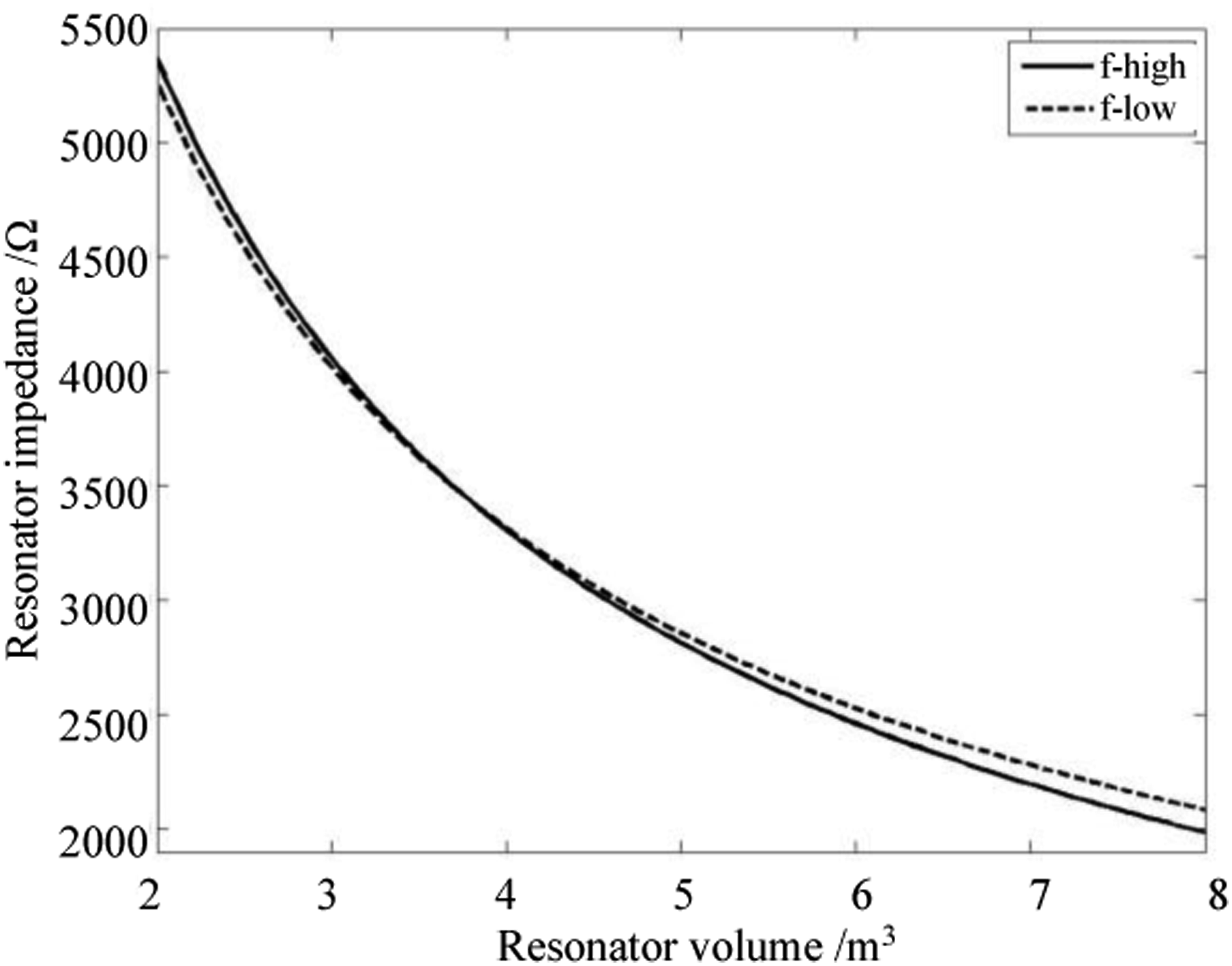
In addition, the resonators are set as two cubes with equal side lengths, the main exhaust pipe is a circular tube with a radius of 0.125 m, and the resonance tubes are two circular tubes with a radius of 0.125 m. The volume of continuous change in the range of 2∼8 m3 is calculated, which is the volume sum of two cubes. The purpose is to calculate the law of the resonator impedance changing with the volume at the same resonance frequency and automatically calculate the length of the required resonance tube and the exhaust pipe during the calculation process. Figure 13 is the result of the calculation of fixing the high-end resonance frequency at 12 Hz and the low-end resonance frequency at 1 Hz. It can be seen that the impedance decreases with the increase in the volume of the resonator. The impedance is about 5300 Ω when the volume is 2 m3, and the impedance is about 2100 Ω when the volume is 8 m3. When the volume is less than 3.8 m3, the impedance of the high-end resonance frequency is greater than the impedance of the low-end resonance frequency. When the volume is greater than 3.8 m3, the impedance of the high-end resonance frequency is less than that of the low-frequency resonance frequency.
Combining these two laws, it can be seen that increasing the sound absorption coefficient of the resonator’s inner wall and increasing the resonator’s volume can reduce the resonator’s impedance.
Impedance-matching design and experimental verification
Impedance-matching design
It can be seen from the previous analysis that the impedance of the modulator and the resonator will change with the change in geometric size, air source, sound absorption coefficient, and other parameters. The air source parameters and the sound absorption coefficient in the resonator may change to a certain extent during use. If the measuring instrument or other items are placed in the resonator, the volume of the resonator will decrease. Therefore, impedance matching should be considered within a range of matching rather than a single numerical matching.
For the working frequency in the range of 5∼15 Hz, the impedance of the modulator can be controlled in the range of 2000∼3000 Ω by selecting appropriate design parameters. Similarly, the resonator impedance can be maintained in the 2000–3000 Ω range.
The design parameters of the modulator are taken as the modulator parameters of this paper, and the impedance is 2248.3 Ω when the working frequency is 12 Hz. The design parameters of the resonator are taken as the resonator parameters of this paper. When the sound absorption coefficient of the inner wall of the resonator is 0.013, the impedance of the high-end resonance frequency of 12.8 Hz is 2335.8 Ω. In this way, the impedance matching of the working frequency of 12 Hz is realized. Although the impedance and resonance frequency of the modulator and the resonator will change in practical applications, the range of change should not be large, and impedance matching can be achieved within a specific range.
Experimental verification
According to the above impedance-matching design scheme, a low-frequency and high-intensity acoustic generator with a 6.2 m3 double-chamber resonator as the main body is designed and verified based on the closed space high-intensity acoustic generator manufactured by the author of this paper. 29 The experimental results show that when the high-end resonance frequency is 11 Hz, the intensity of the 11 Hz acoustic wave in the resonator reaches 160 dB, and the low-end resonance frequency is less than 3 Hz. The intensity is much larger than the intensity of 11 Hz, indicating that the impedance of the low-end resonance frequency is greater than that of the high-end resonance frequency. It proves the conclusion that the impedance of the high-end resonance frequency is less than the impedance of the low-frequency resonance frequency when the volume is greater than 3.8 m3. It also shows that the sound absorption coefficient of the inner wall of the resonator should be less than 0.017, and the sound absorption coefficient of 0.013 taken in the calculation of this paper is also basically reasonable.
Boesch et al. 28 achieved an acoustic intensity greater than 155 dB (13 Hz) with impedance matching, while in their early device HILF1, the modulator impedance was about 70 kΩ, which did not match the resonator with an impedance of about 2000 Ω, so the acoustic intensity in the resonator was only more than 140 dB. 27 In contrast, the impedance-matching scheme in this paper achieves a high acoustic intensity of 160 dB (11 Hz), which proves that the matching scheme of this paper is successful.
Discussion and conclusions
In this paper, the impedance calculation formula of the double-chamber Helmholtz resonator based on electro-acoustic analogy is derived, and the laws of the impedance changing of the modulator and the resonator with the main parameters are calculated. The results show that the impedance of the modulator can be reduced by increasing the air chamber’s volume, increasing the stator’s width, reducing the air supply pressure, reducing the air supply flow, and increasing the working frequency. Increasing the resonator’s inner wall’s sound absorption coefficient and the resonator’s volume can reduce the resonator’s impedance. The impedance-matching design of the low-frequency and high-intensity acoustic generator is given. The experimental results show that the impedance calculation method and impedance-matching design of the modulator and the resonator are correct. If FLUENT and other software are used for numerical simulation, the details of the acoustic generation process can be obtained, but only for the simulation of a particular parameter. It is challenging to analyze the change of acoustic generation law caused by parameter change because the workload and time-consuming of multiple simulations of changing parameters are enormous. The theoretical calculation method in this paper cannot give the detailed process and characteristics of acoustic wave generation. Still, it can quickly and accurately analyze the influence of multiple parameters on acoustic intensity. Therefore, this method has particular guiding significance for designing high-intensity acoustic generators in closed spaces and can effectively improve acoustic generation efficiency and intensity.
Footnotes
Acknowledgements
The authors wish to thank Professor Guozhen Guo, associate Professor Jin Wang, and Shenglong Xu for their support and help in this work.
Author contributions
All authors contributed to the study’s conception and design. Material preparation, data collection, and analysis were organized and managed by Mingrong Dong. All the authors took part in the experiment. Baoguo Zhang and Mingrong Dong wrote the first draft of the manuscript. All authors commented on previous versions of the manuscript. All authors read and approved the final manuscript.
Declaration of conflicting interests
The author(s) declared no potential conflicts of interest with respect to the research, authorship, and/or publication of this article.
Funding
The author(s) received no financial support for the research, authorship, and/or publication of this article.
Data availability statement
The data supporting this study’s findings are available from the corresponding author upon reasonable request.