
Abstract
Due to the incurred damages to the combustors, large-amplitude self-sustained thermoacoustic oscillations are unwanted in many propulsion systems, such as liquid/solid rocket motors and aero-engines. To suppress these thermoacoustic oscillations efficiently, the mechanism of thermoacoustic instability needs to be clarified. Following the previous experimental work, the transitions to instability in a Rijke-type thermoacoustic system with an axially distributed heat source are studied numerically in this paper. The URANS numerical method is utilized and verified by means of a mesh sensitivity analysis. The influences of the axially distributed heater length, the heater location, and the mean flow velocity on the nonlinear dynamic behaviors of thermoacoustic oscillations are evaluated. To explore the corresponding mechanism behind these influences, the principle of acoustic energy conservation has been applied. The acoustic energy gains from the thermal-acoustic coupling are quantified via Rayleigh’s integral, and their phase differences are calculated by the cross-correlation function. The acoustic damping induced by the vortex dissipation is qualitatively analyzed by the characteristics of the flow fields in the Rijke tube. Finally, as the heater length, the heater location, or the mean flow velocity is varied, three mechanisms of the transitions to instability in a Rijke-type thermoacoustic system are identified.
Keywords
Introduction
Energy conversion from heat to sound is desirable in thermoacoustic engines (TAEs)1–4 due to its advantages in fewer moving parts and non-exotic materials compared to internal combustion engines, steam turbines, etc. Nevertheless, it is unwanted in aero-engines and land-based gas turbines5–8 for the incurred large-amplitude thermoacoustic oscillations which would cause severe damages, such as jet panel ablation and structural vibration. The heat to sound energy conversion is generally caused by the coupling between the heat release rate pulsation and the internal acoustic field in the combustion chamber.9–12 With the increasing stringent requirement of low-emission and high combustion efficiency, combustion instability becomes more popular in the new generation of gas turbines. To suppress and predict thermoacoustic oscillations in combustion systems,13,14 it is essential to figure out the mechanism of thermoacoustic instability.
Considering the fact that the actual energy conversion from heat to sound is complex by the interactive coupling between flow, temperature, and acoustic field in real combustion systems, direct investigation of the mechanism of thermoacoustic instability would encounter long periods and expensive costs. It is believed that the study on the generation mechanism of the Rijke-type thermoacoustic instability could facilitate the understanding of thermoacoustic instability occurring in the more complex practical system.15–19 Based on a bifurcating Rijke-type combustor, Zhao evaluated the performance of the Helmhotlz resonator 20 and a multi-input/single-output tuning strategy 21 on damping self-sustained thermoacoustic oscillations, and the amplitudes of the limit cycle oscillations were simultaneously reduced in the two outlet branches. In addition, Zhao 22 introduced a temperature-variable heat exchange into the Rijke-type thermoacoustic system which utilized an ammonia/hydrogen combustion system as a heater source. After evaluating the damping capability of the heat exchange on the thermoacoustic oscillations, it was found that this approach was not a potential way to deal with the unfavorable oscillation in the practical engines.
Previous work generally chose some compact heater to provide the unsteady heat release rate. Matveev 23 designed a thin nickel-chromium alloy screen to predict the stability boundary of the horizontal Rijke tube thermoacoustic system in terms of the heater power and air flow rate. Li 24 introduced the classic n-τ model via the Dirac function to represent the compact energy source, analyzed the influence of the flow-acoustic coupling strength and the averaged temperature ratio before and after the combustion zone, and explained how these factors affect the response of the Rijke tube. Chow 25 evaluated the stability of the system in terms of a hydrodynamic region adjacent to the flame holder and concluded that the frequency of thermoacoustic oscillations strongly depends on the location of the hydrodynamic region. Balasubramanian 26 studied the influence of non-normality and nonlinearity on thermoacoustic responses, in which the heat release rate of the heating element is modeled by a modified King’s Law and introduced via the Dirac function. Based on the same theoretical model, Subramanian 27 obtained the nonlinear bifurcation diagrams in terms of heater power and heater location, and found that increasing the heater power would make the thermoacoustic system more prone to large-amplitude oscillation, and the unstable heater location for the compact heater source is around 0.15∼0.4. Zhao28,29 took the temperature distribution caused by laminar premix flame into account and predicted the most “dangerous” position by analyzing the maximum transient growth rate of acoustic energy.
However, it is worth noting that most previous researches on Rijke-type thermoacoustic systems have been limited to an infinitely thin heat source. In theoretical analysis, the unsteady heat release is regarded as a single concentrated plane and is usually represented by a form of the Dirac delta function. In the experimental studies, the heat source can be provided by thin flakes with small thicknesses. But in the real propulsion system, the combustion process in the combustor chamber is distributed over a nontrivial length of the combustor. For example, in a solid rocket engine with a large amount of aluminum propellant, the metal fuel cannot burn out on the thin combustion surface initially, and it would distribute near the centerline of the combustor and take reaction in a large region in the axial direction. The distributed combustion process would couple with the acoustic waves and be one of the main energy sources for driving thermoacoustic oscillations. 30 In aero-engine annular combustors 31 and liquid rocket engines, 32 the combustion process involves a series of physical and chemical processes, including injection, atomization, evaporation, premixing, and chemical reaction, which elongates the reaction zone in the longitudinal and tangential directions. Therefore, in real thermoacoustic systems, the combustion region is always distributed.
In recent years, the effects of distributed heat sources on thermoacoustic instability have attracted more and more attention. Li33,34 studied the effect of non-uniform circumferential and axial distribution of heat release rate on a thermoacoustic system by establishing a three-dimensional thermoacoustic model. It was found that the non-uniform circumferential distribution has a significant effect on the oscillation frequency and growth rate. The longer the heat source axially distributed interval is, the greater the maximum transient growth rate is, thus increasing the possibility of triggering instability. Du 35 conducted an experimental study on tangential heat source distribution in the Rijke tube, and the experimental data proved that there was a dangerous spacing to maximize the stability boundary and the amplitude of thermoacoustic oscillations. Dowling 36 applied the linear stability theory to study the effect of an axially distributed heat source on the longitudinal instability in a tube with the inlet choked and the outlet opened, and found that the length of the axial heat source has a significant effect on the frequency of thermoacoustic oscillation when the temperature ratio across the heater is larger. Li 37 designed a coiled-wire heater source to represent the axially distributed heat source and studied the transition to instability in a Rijke tube. The influences of the characteristics of heat source, mass flow rate, and tube materials on the nonlinear dynamic behaviors and stability boundaries are evaluated. To reproduce the nonlinear thermoacoustic oscillation numerically in the open-open and closed-open Rijke tube, Hantschk38,39 proposed a banded heater with multiple-concentric constant-temperature rings as a heater source and chosen a thermal conductivity which is 10 times higher than the reasonable value in a Rijke tube. Zhao 40 used the similar heater source in a convection-driven T-shaped thermoacoustic system model and studied the nonlinear coupling between unsteady heat release and acoustic disturbances.
Following our previous experimental investigations in Ref. 37, this paper utilizes the method of numerical simulation to explore the internal mechanism for the large-amplitude pressure oscillation in the Rijke-type thermoacoustic system with an axially distributed heat source. Firstly, the geometric configuration and the numerical methodology are described Secondly, the effects of the axially distributed heater length, heater location, and the mean flow velocity on the stability of the thermoacoustic system as well as the related mechanisms are discussed. Finally, the main conclusions are summarized.
Numerical methodology
Geometric configuration
A Rijke-type thermoacoustic system with an axially distributed heat source is studied. The configuration is shown in Figure 1. It is comprised of a straight tube with both ends opened and a heating element inside. The tube has an overall length of 1 m and a diameter of 50 mm, and it is placed horizontally to work as an acoustic resonator. An axis-symmetric annular heater band with a blockage ratio of 0.46 is placed at Schematic of a Rijke-type thermoacoustic system and the computational grid in the region of the heating element. A 2D axis-symmetric model is applied.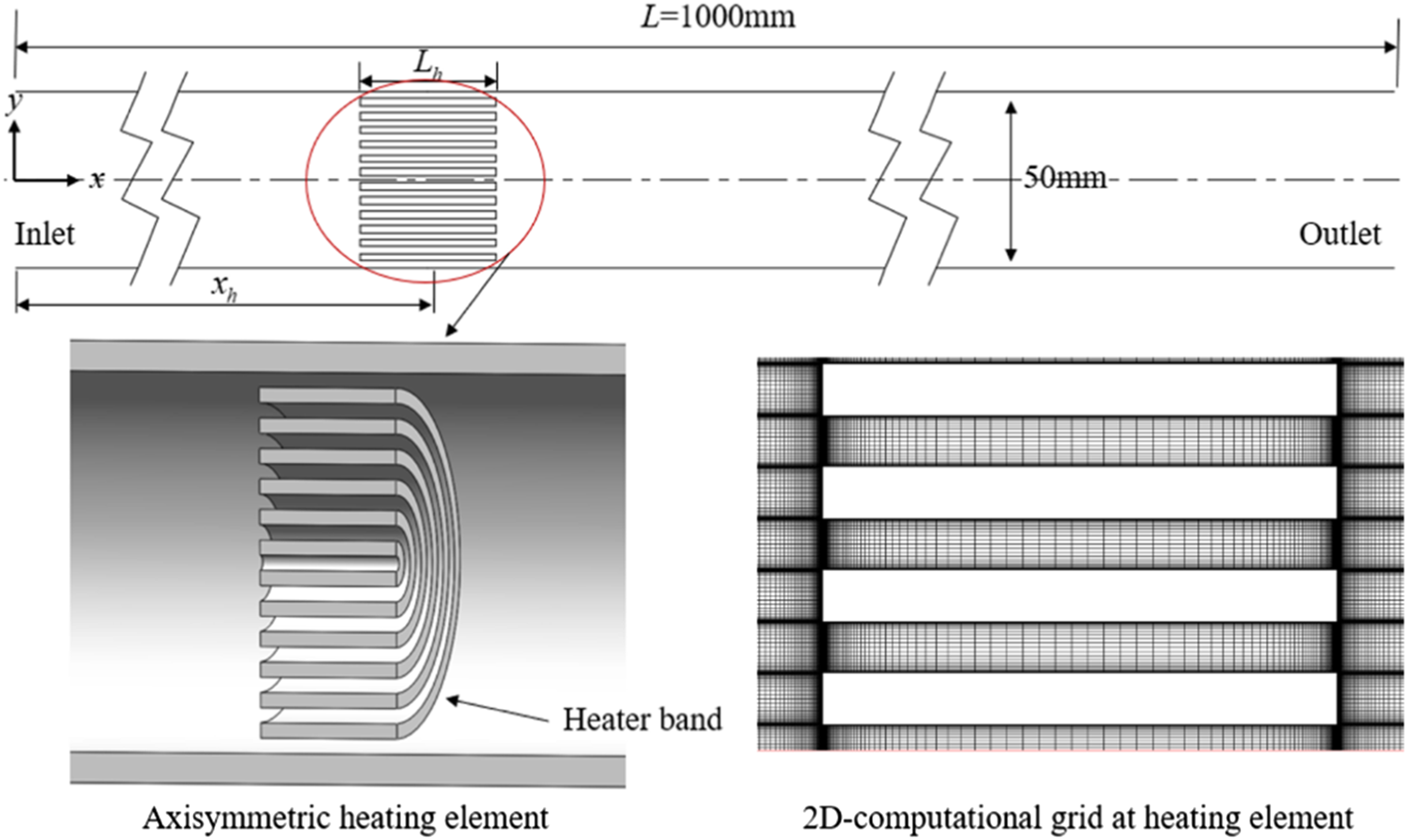
Governing equations
In this paper, 2D numerical investigations of the unstable pressure oscillations and heat oscillations in the Rijke-type thermoacoustic system are conducted by the URANS (unsteady Reynolds Averaged Navier–Stokes) method.
41
For compressible flows, the mean fluid variables can be represented as


To model the Reynolds stresses, a Boussinesq hypothesis
42
is used, that is


The transport equations for the SST k-ω model are given as


Numerical algorithm and boundary conditions
To solve the above governing equations, the finite volume method is utilized. The Back-Euler difference method is employed for the temporal difference. The second-order central difference scheme and second-order upwind scheme are used in spatial difference to discretize the diffusion terms and convection terms, respectively. The PISO algorithm for the pressure-linked equations is adopted to solve the pressure field.
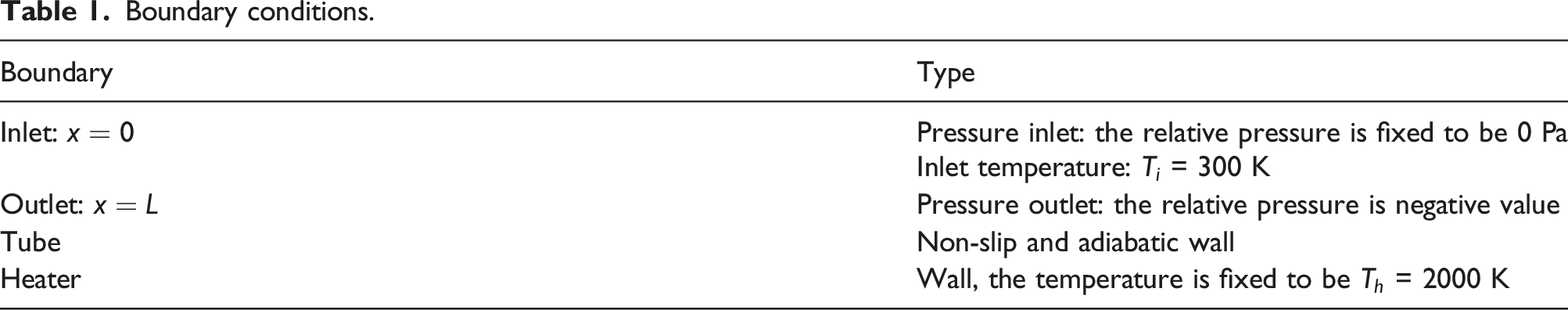
Boundary conditions.
During the calculation, a better initial flow field was obtained by steady-state calculation first, and then transient calculation was carried out. The time step was set as
Model dependence study
To monitor the system response within the Rijke tube, nine evenly distributed points are set up along the Rijke tube, as is shown in Figure 2. Here P1 and P9 are placed at the inlet and outlet of the Rijke tube, respectively. Distribution of monitoring points along the tube.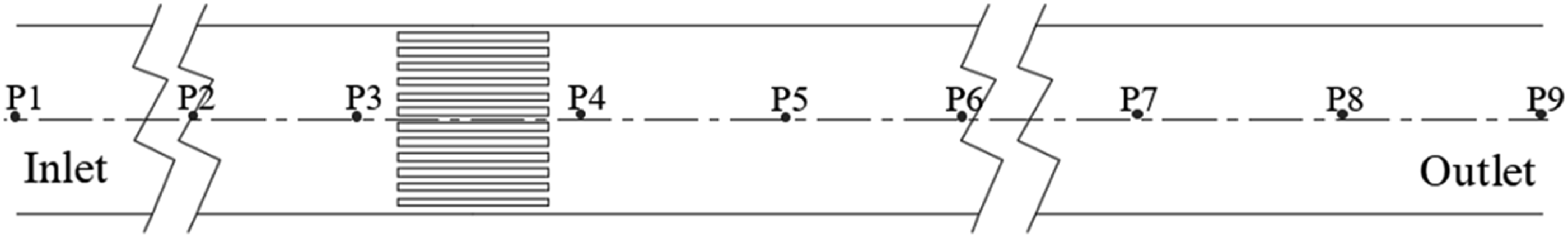
The grid adopts regular quadrilateral structures in the 2D model. The numerical method is verified by means of a mesh sensitivity analysis. Six different computational meshes, ranging from 100,000 to 320,000 node numbers, are evaluated for two-dimensional grid verification. The thermoacoustic system is first configured as follows: the axial heat source location is Comparison of the most excited pressure amplitude 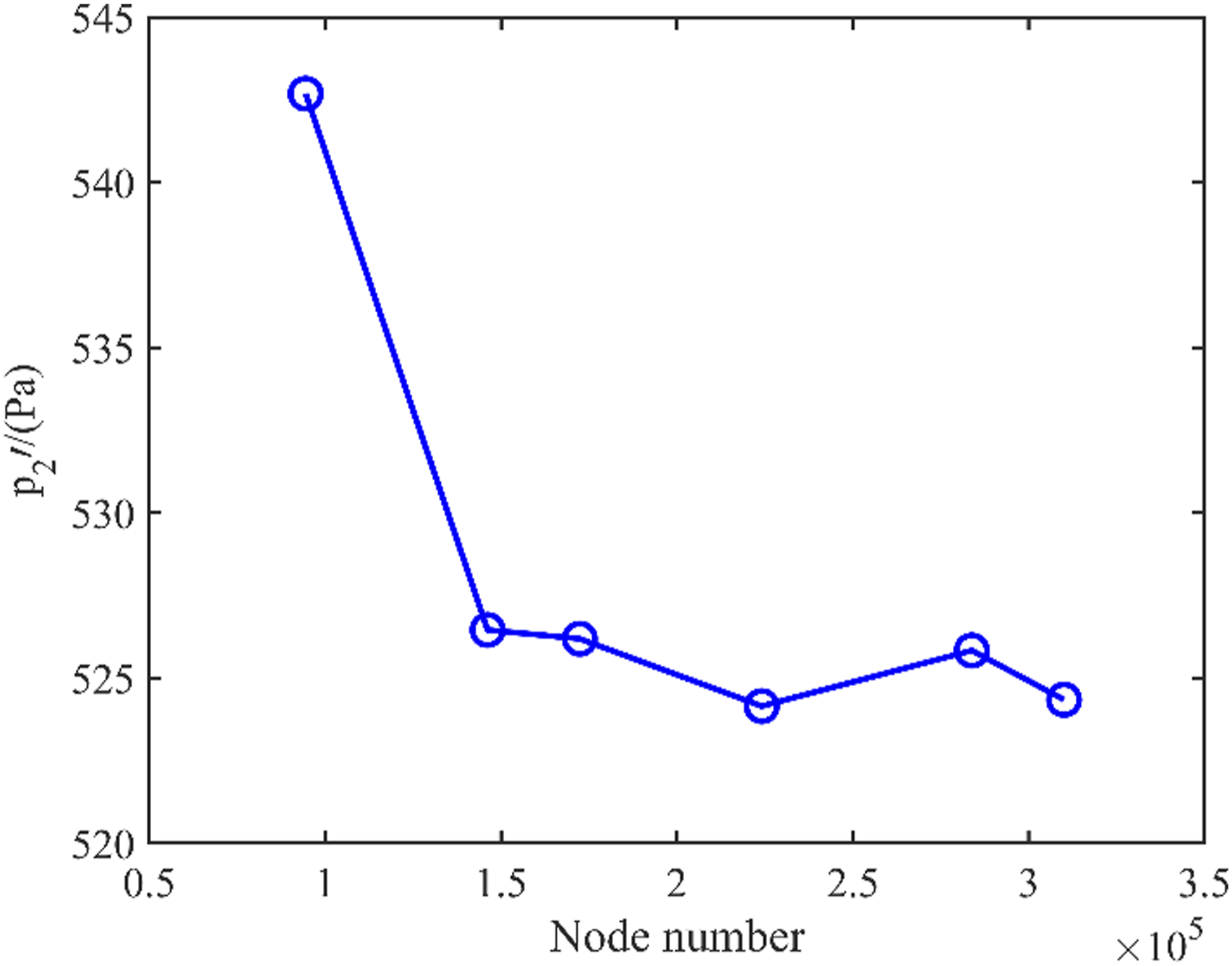
Results and discussion
The parameters involved in this paper mainly include: (1) the axial heat source location x
h
, (2) the axial heat source length L
h
, and (3) the mean flow velocity
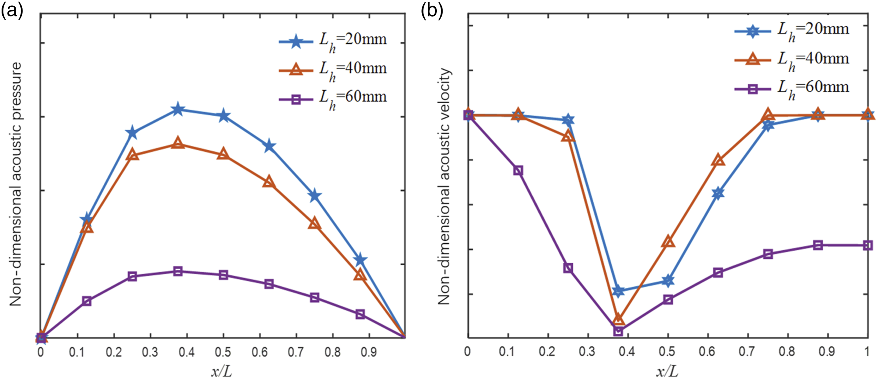
Figure 4 shows the time traces of acoustic pressure via the previous numerical model, and both of the exponential growth and large-amplitude pressure oscillation are observed. Figure 5 shows the acoustic pressure mode shape and corresponding acoustic velocity mode shape when the heater length is varied. It can be seen that the acoustic pressure is maximized near the center of the tube (Figure 5(a)), and the acoustic velocity is maximized at both ends of the tube. Due to the occurrence of the heat source and the flow disturbance, the acoustic velocity node is shifted to the upstream part. Time evolution of the self-sustained acoustic oscillation. (a) The non-dimensional acoustic pressure mode shape 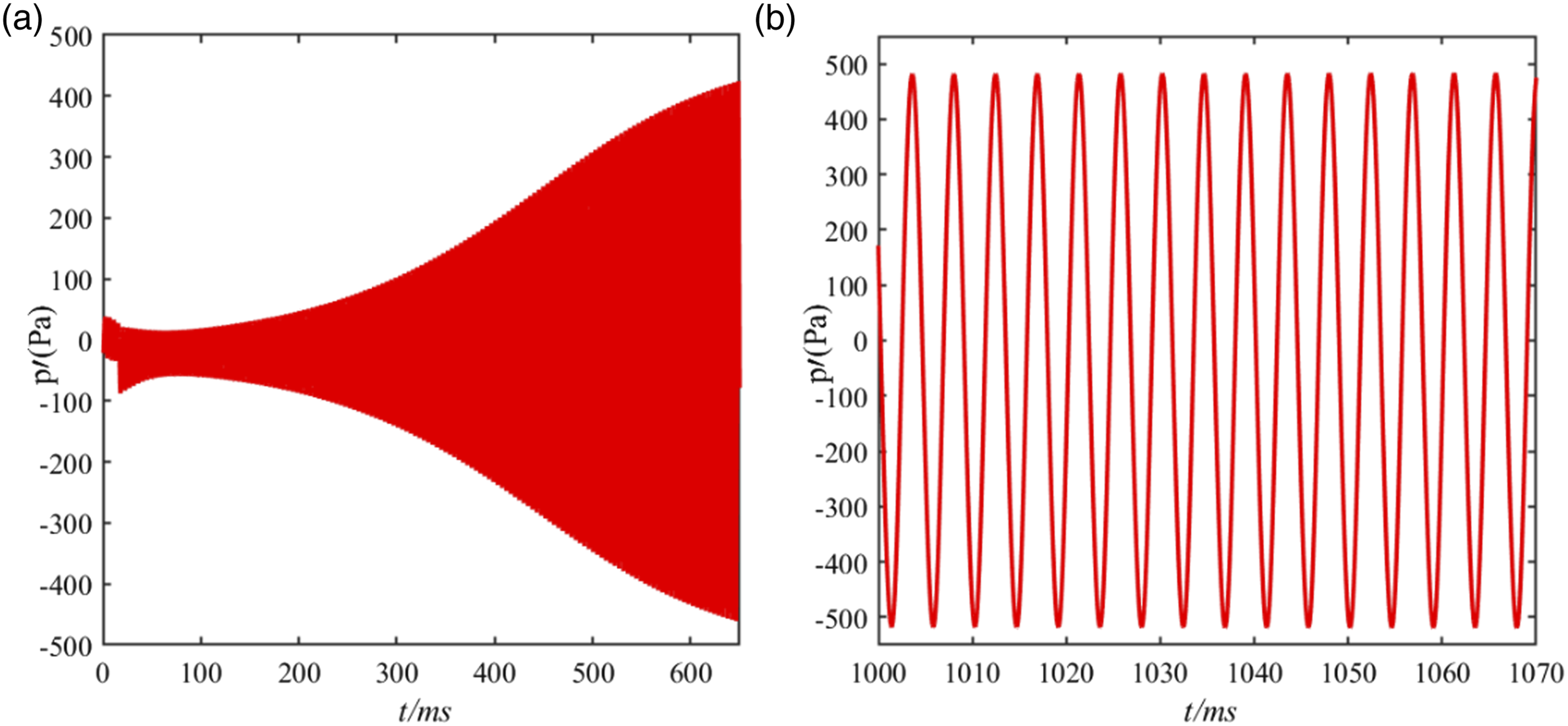
Effects of the axial heater location
Then, the effects of the axially distributed heat source location on the stability of the Rijke-type thermoacoustic system are investigated in Figure 6, as the heat source length is Amplitude of thermoacoustic oscillation under different heat source locations, as 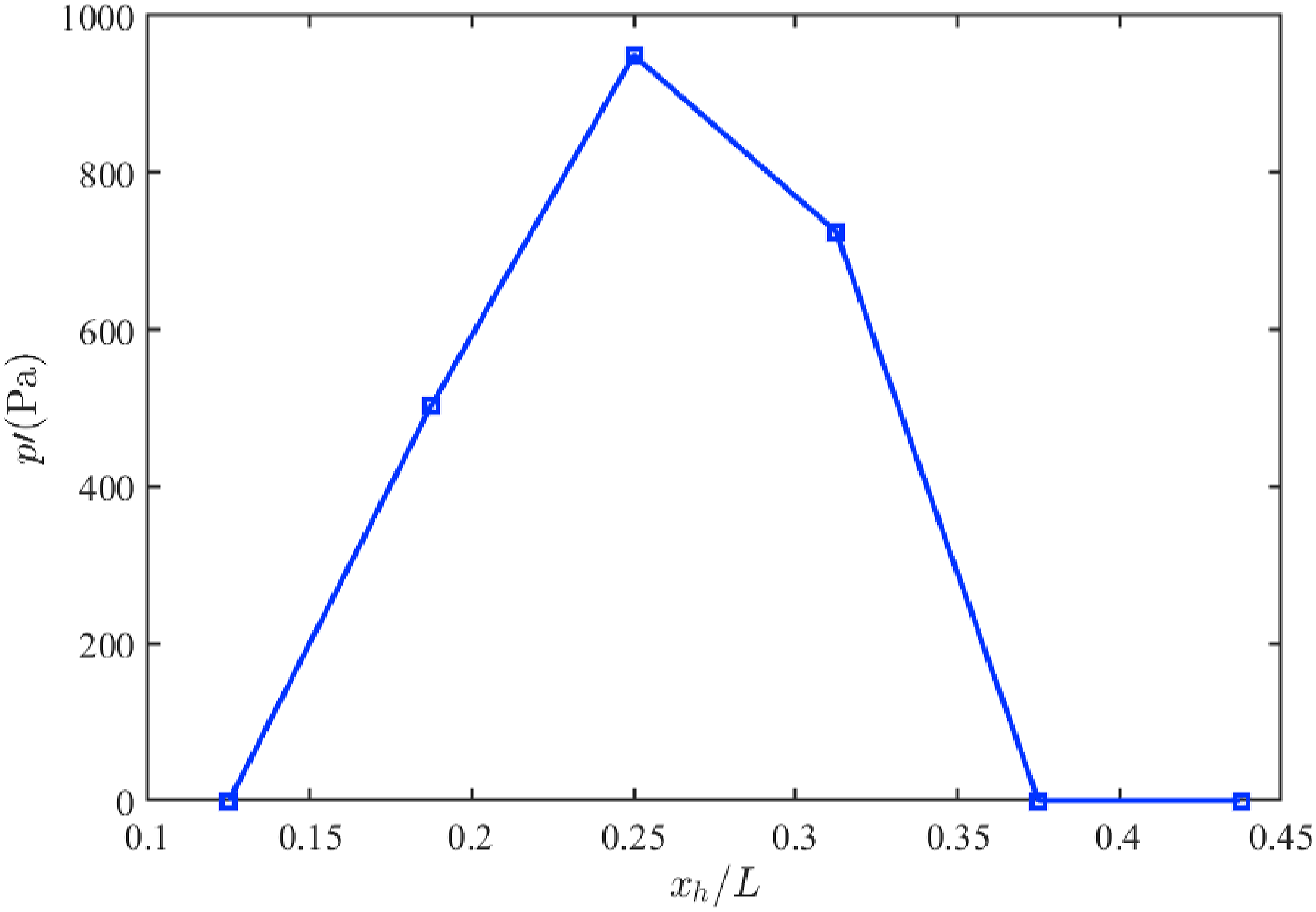
To explore the mechanism behind the variation trends further, the principle of energy conservation is applied. Here, the acoustic energy gain from the coupling between the unsteady heat release rate and acoustic pressure can be evaluated by the Rayleigh’s criterion,
43
and it has been mathematically derived40,44,45 and explicitly expressed as
Based on the cross-correlation function, the phase difference between acoustic pressure oscillation and heat release rate oscillation of a thermoacoustic system can be obtained via the following expression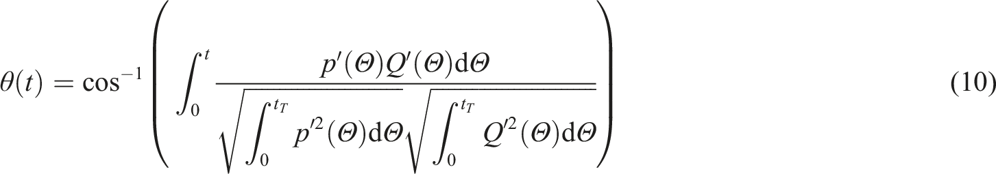
Figure 7(a) evaluates the cross-correlation function (a) The cross-correlation function for the acoustic pressure and unsteady heat release rate; (b) Acoustic pressure pulsation and heat release rate pulsation, as 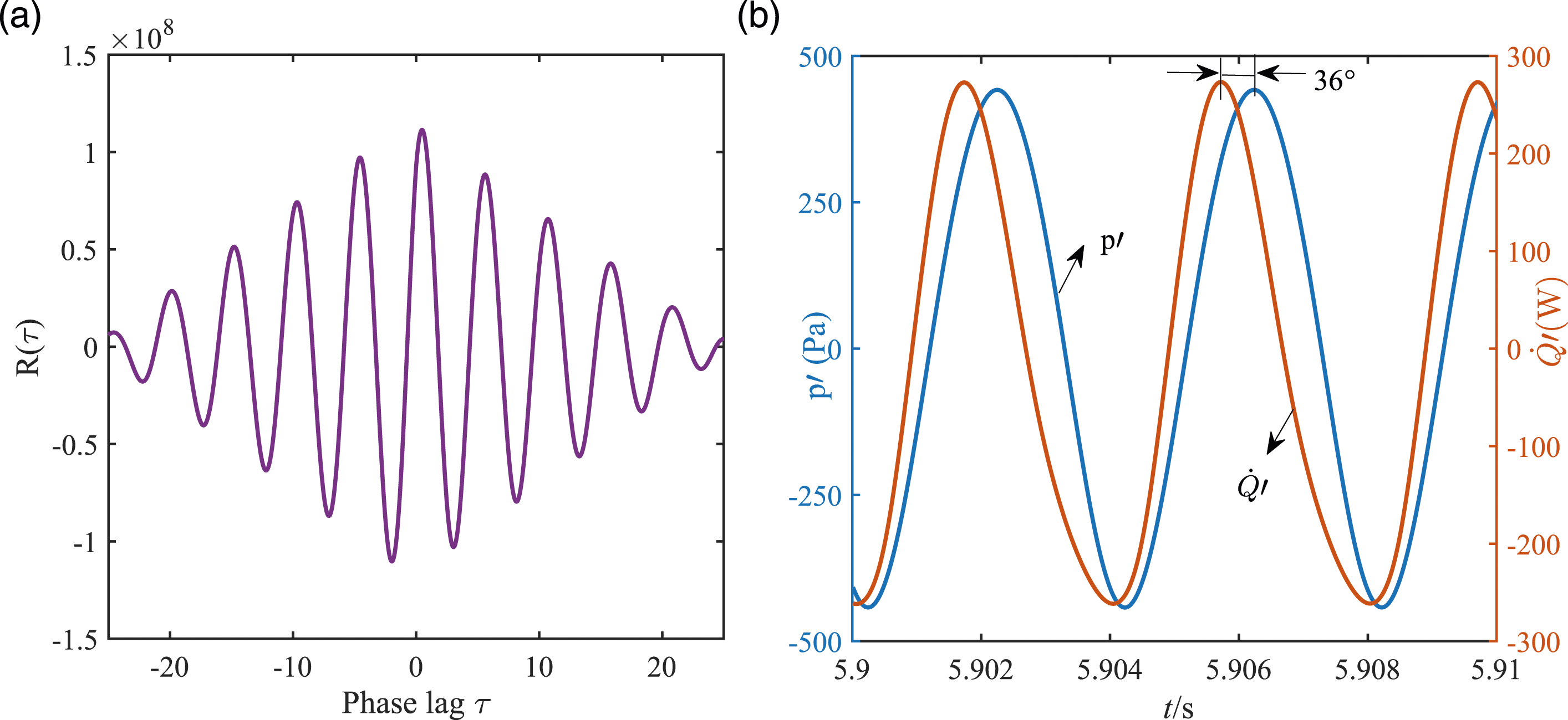
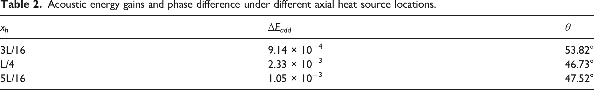
Acoustic energy gains and phase difference under different axial heat source locations.
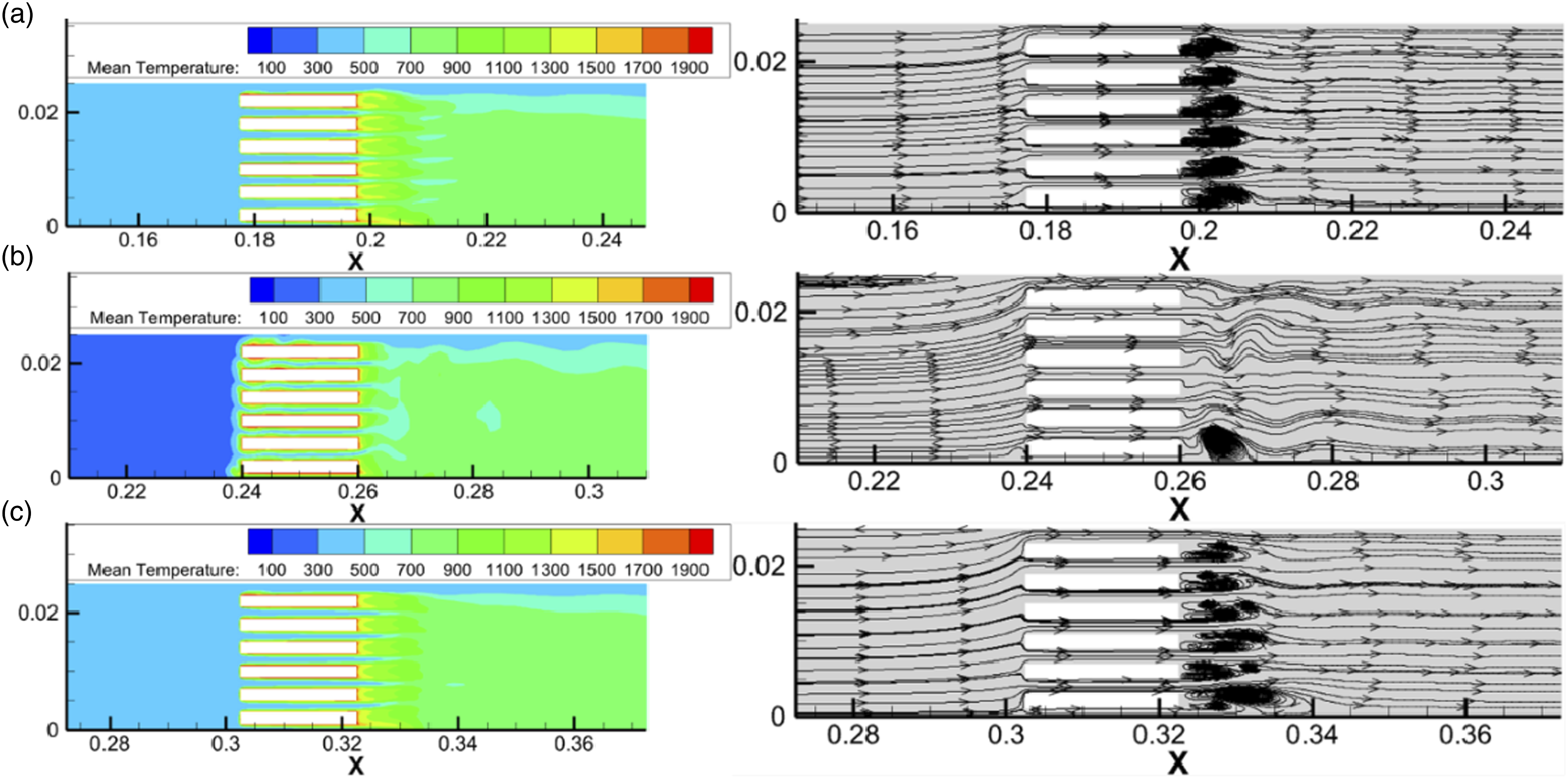
The time-averaged temperature contour and time-averaged flow field near the heating element under different axial heat source locations, as
For the effects of the axial heat source location on the frequency of thermoacoustic oscillations, Figure 9 shows that the thermoacoustic oscillation frequency is decreased, as the heater is moving downstream. It can be seen from Figure 10 that the hot region is decreasing, when the heat source moves downstream, which results in a decrease in the mean temperature and mean sound speed. Therefore, the resonant frequency of the acoustic oscillation in the tube declines. Thermoacoustic oscillation frequency under different axial heat source locations, as The time-averaged temperature contour under different axial heat source locations, as 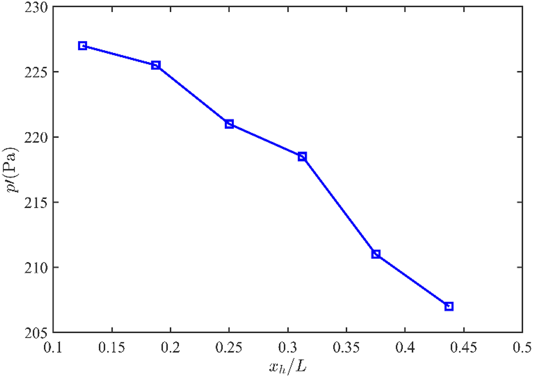
Effects of the axial heater length
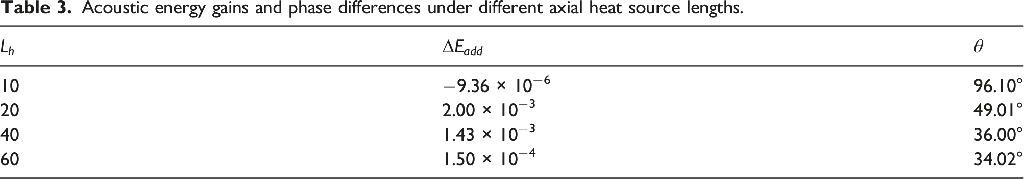
Second, the effect of the axial heat source length on the stability of the Rijke-type thermoacoustic system is studied numerically in Figure 11. The amplitude of pressure oscillation in the tube increases first and then decreases gradually, when the axial heat source length is increased. There is an optimal axial heat source length, which makes the thermoacoustic oscillation being most intense. Amplitude of thermoacoustic oscillation under different axial heater lengths, as 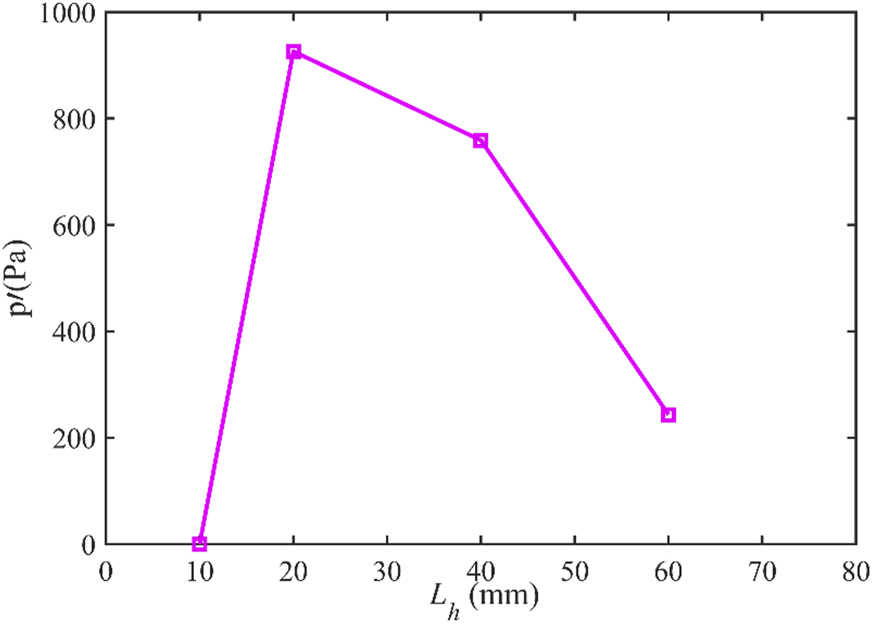
Acoustic energy gains and phase differences under different axial heat source lengths.
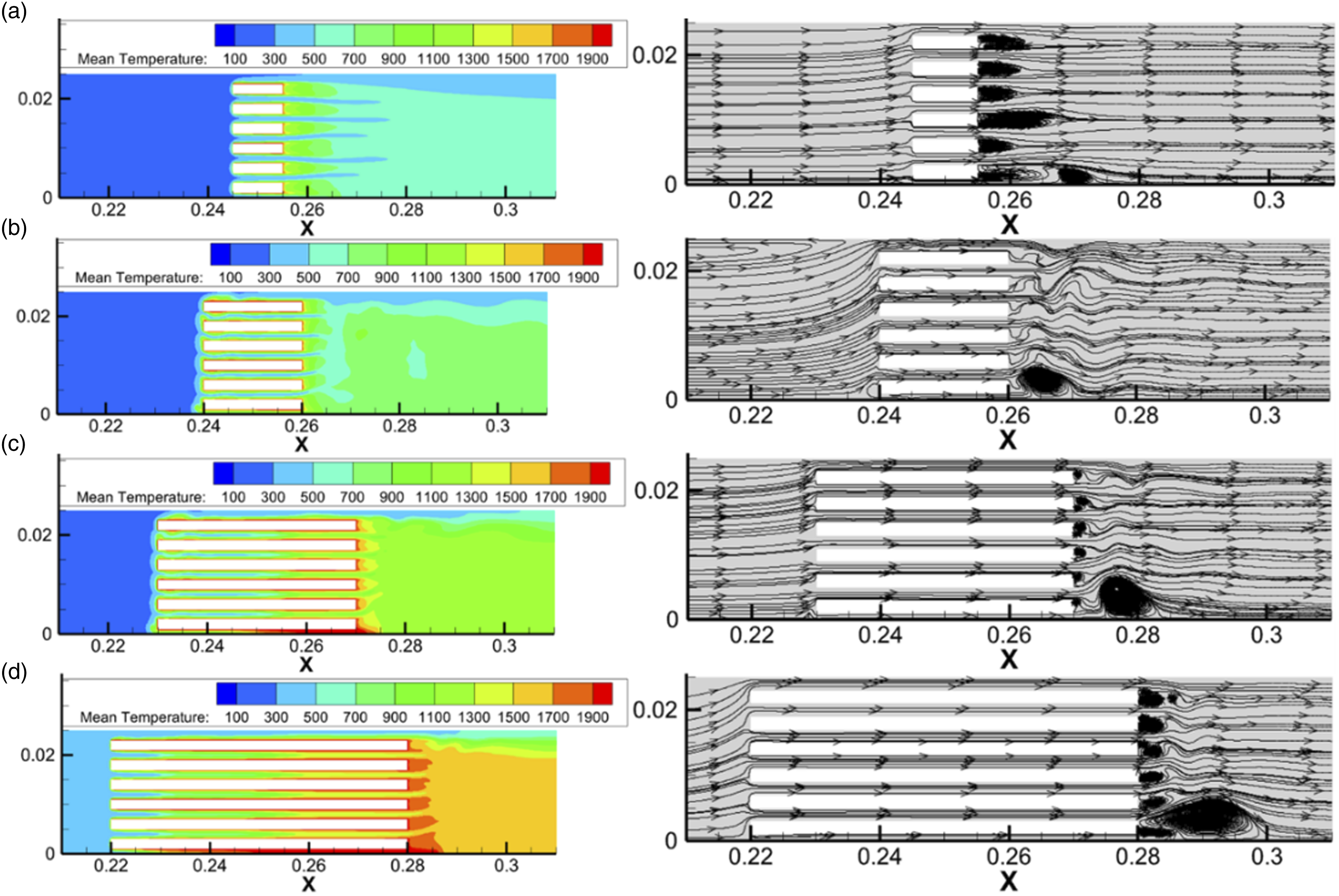
The time-averaged temperature contour and time-averaged flow field near the heating element under different axial heat source lengths, as
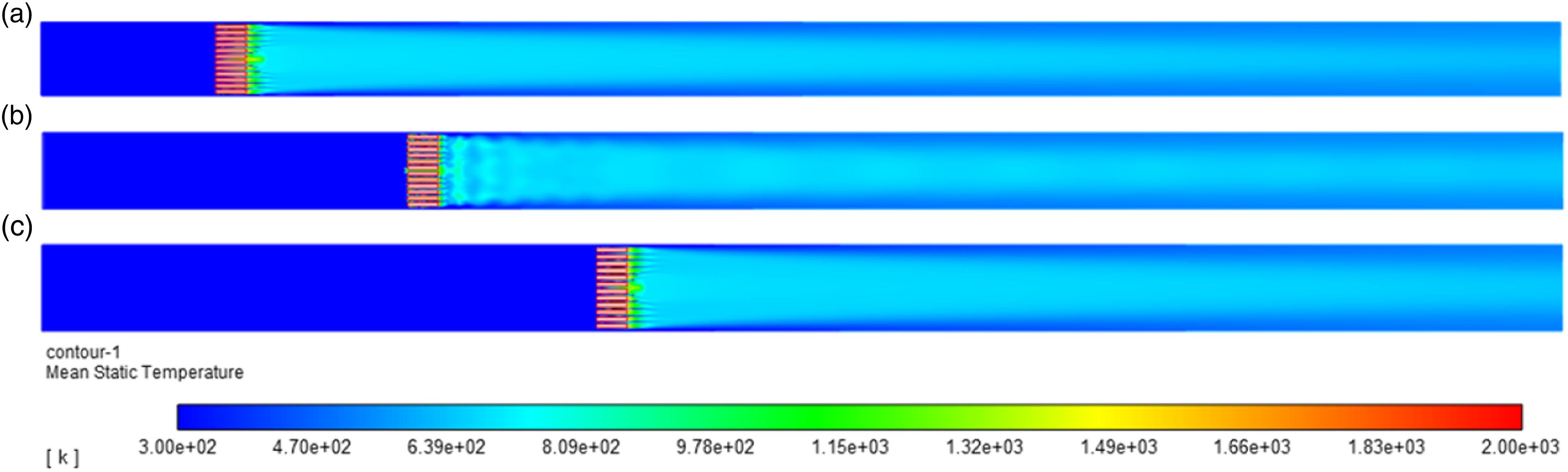
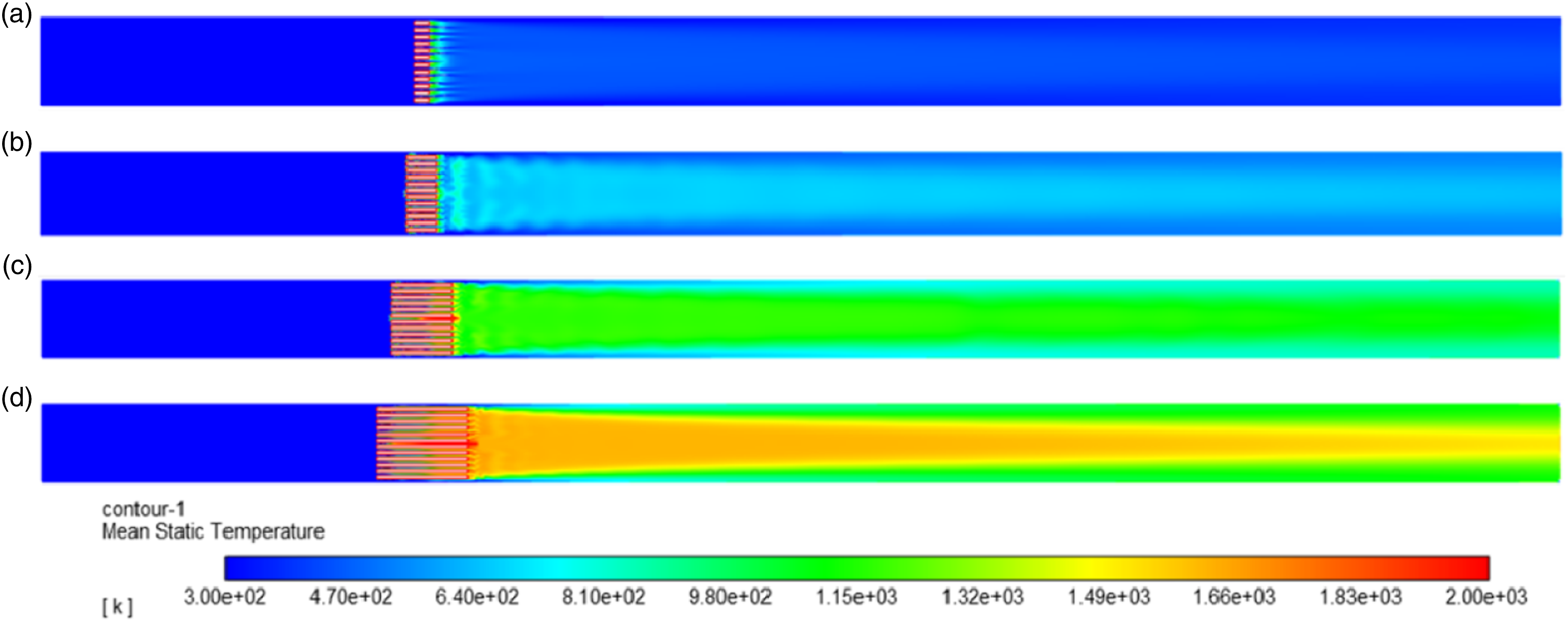
Then, the frequency of the thermoacoustic oscillation is evaluated in Figure 13. The curve shows that the frequency of pressure oscillation in the Rijke tube is increased, as the axial heat source length is increased. The reason behind this is explored in Figure 14, where the temperature contours are illustrated in the whole tube. It can be seen that, when the airflow passes through the heat source, the mean gas temperature increases obviously, and then decreases to a relatively stable value. With the increase of the length of the axial heat source with constant temperature, more heat energy is transferred, resulting in an average temperature rise downstream of the heater source. Finally, a larger sound speed ( The frequency of thermoacoustic oscillation under different axial heat source lengths, as The time-averaged temperature contour under different axial heat source lengths, as 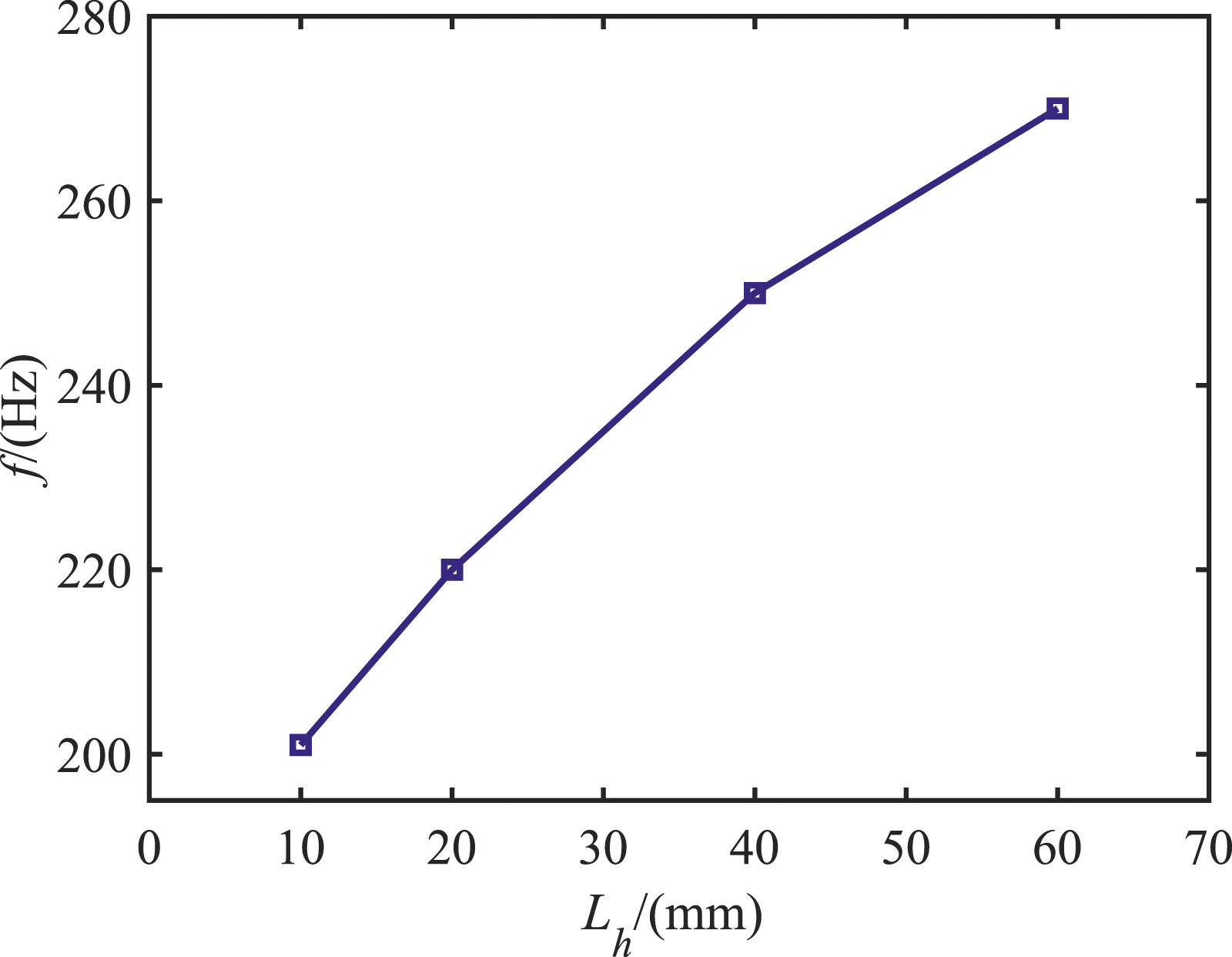
Effects of the mean flow velocity
Last, the influence of the mean flow velocity on the stability of the Rijke-type thermoacoustic system is studied in Figure 15, as the axial heat source location is configured at Amplitude of thermoacoustic oscillation in different mean flow velocities, as 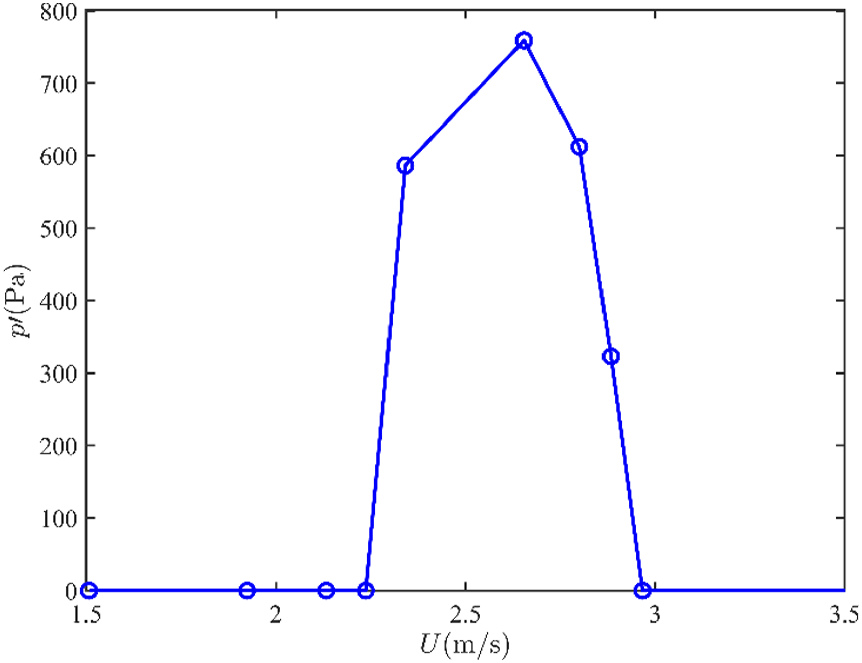
Furthermore, the influence of the axial heater length on the stability range of the Rijke-type thermoacoustic system is studied in Figure 16. It can be seen that the unstable velocity interval is decreased with the increase of the heat source length, and the unstable velocity interval for the longer heat source length is trapped in that for the shorter heat source length. These trends are similar with the experimental measurement in Ref. 37. The main difference is the configuration with Variation curves of the amplitude of thermoacoustic oscillation with mean flow velocity under different axial heat source lengths, as 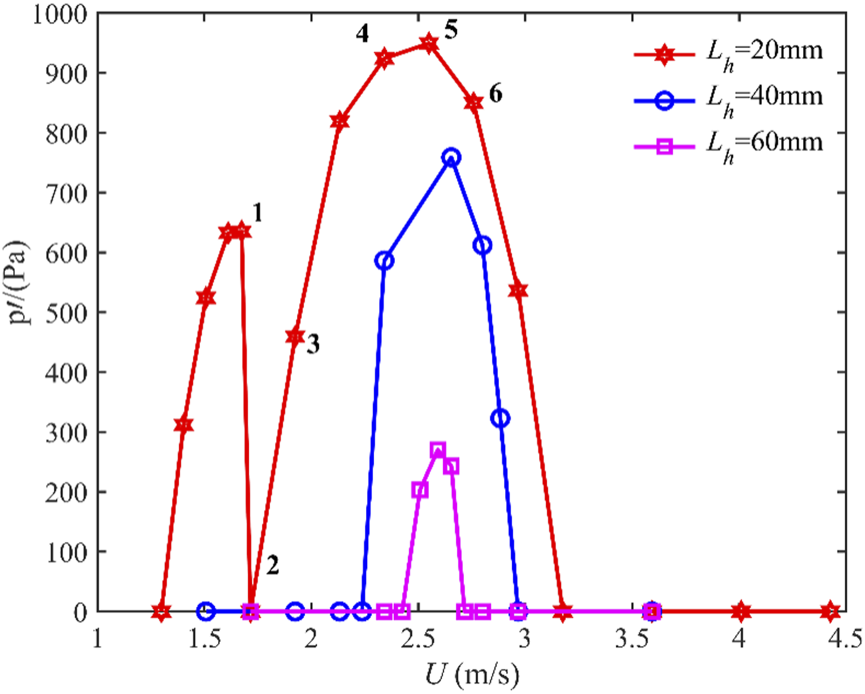
Acoustic energy gains and phase difference under different flow velocities.
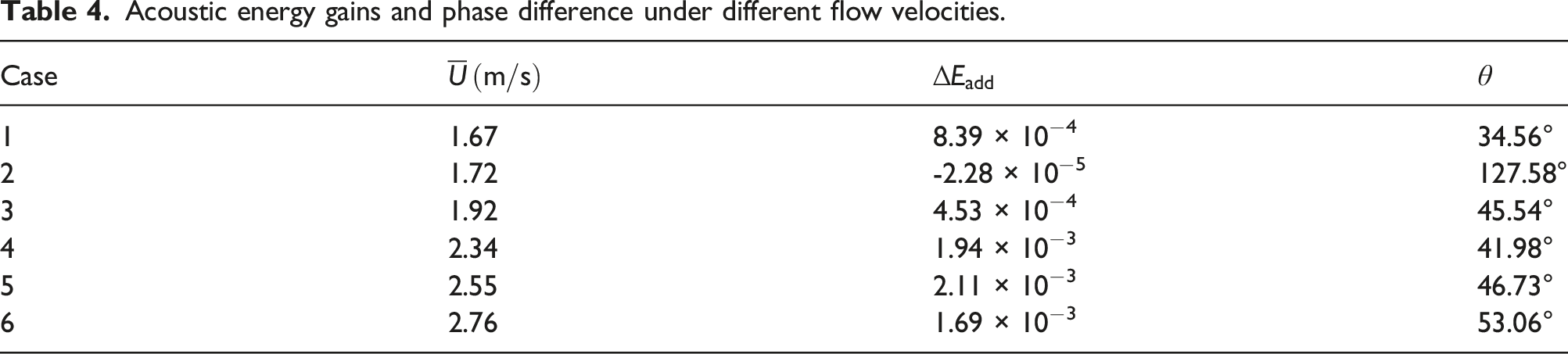
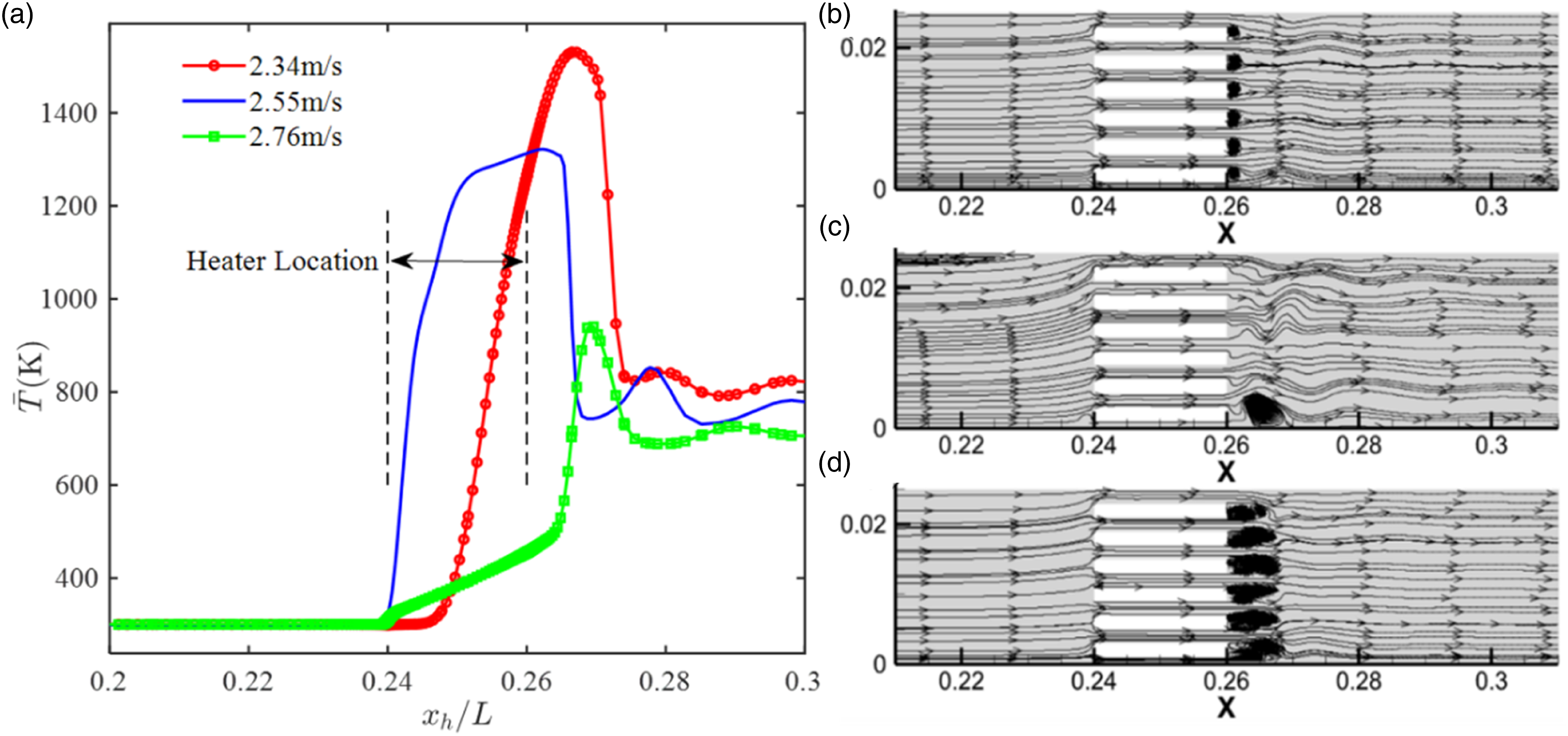
Then, the effects of the mean flow velocity on the acoustic model shape and the mean temperature distribution are further studied. It can be seen from Figure 17 that increasing the mean flow velocity would decrease the acoustic pressure value inside the heater location where the acoustic intensity is maximum in the axial direction. In addition, when The effects of the mean flow velocity on acoustic pressure and acoustic velocity for the low mean flow velocity. The time-averaged temperature and time-averaged flow field near the heating element under different incoming flow velocities, as 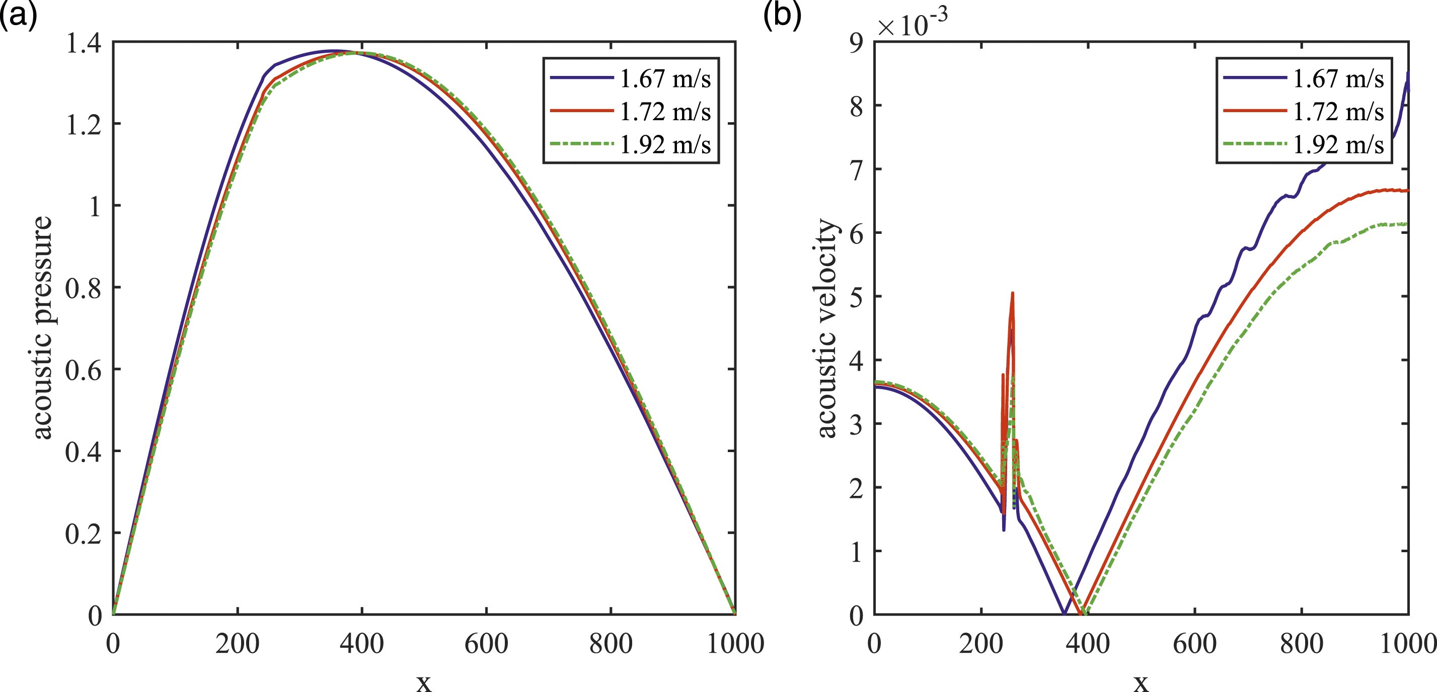
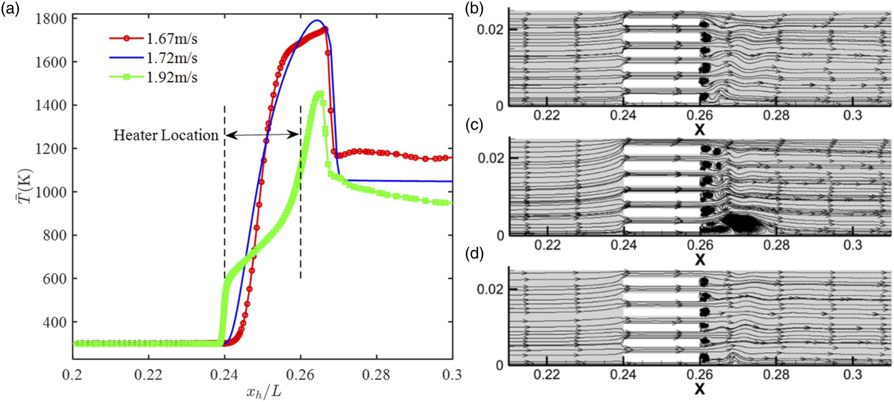
When the mean flow velocity is increased to a large value, that is, The effects of mean flow velocity on the acoustic pressure and acoustic velocity for the large mean velocity. The time-averaged temperature contour and time-averaged flow field near the heating element under different incoming flow velocities, as 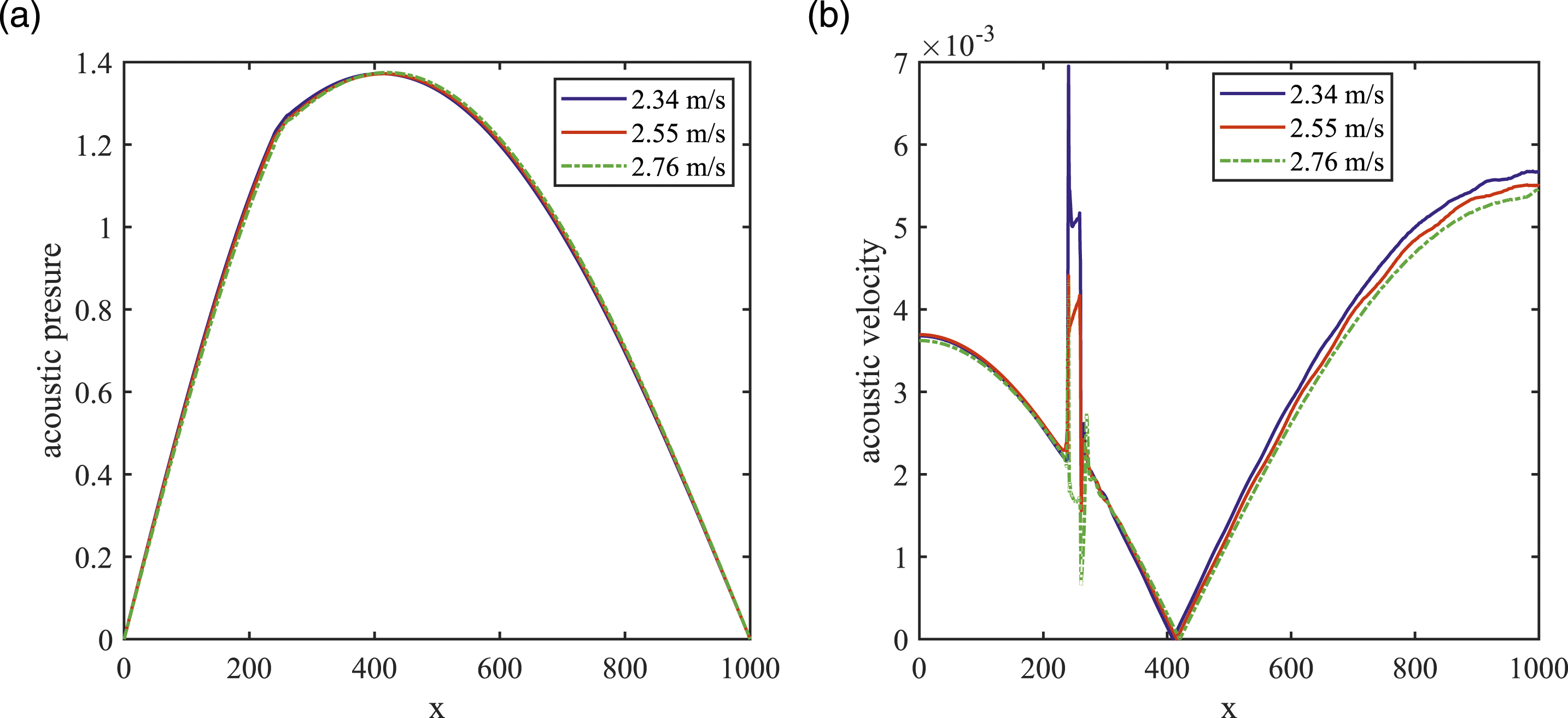
Conclusions
In this paper, a Rijke-type thermoacoustic system with an axially distributed heat source is studied numerically and experimentally. It has been found that the response of the thermoacoustic system is mainly determined by the characteristics of the acoustic waves as the axially distributed heater location is varied. Comparative, the increase of the heater length would lead to large vortices and large acoustic damping, and characteristics of the flow field determine the system response. Furthermore, the influence of the mean flow velocity is further evaluated, and found that, as the mean flow velocity is small, the response of the thermoacoustic system is dominated by the thermoacoustic interaction. However, as the mean flow velocity is large enough, the variation in the flow field and the mean temperature field is dominant, and the phase difference responds nonlinearly as the acoustic energy gain is increased. Last, there are some sensible length and location of the axially distributed heat source and mean flow velocity to incur maximum amplitudes of thermoacoustic oscillation.
Footnotes
Declaration of conflicting interests
The author(s) declared no potential conflicts of interest with respect to the research, authorship, and/or publication of this article.
Funding
The author(s) disclosed receipt of the following financial support for the research, authorship, and/or publication of this article: This study is supported by Young Scientists Fund (Grant number: 52006012).