
Abstract
This paper presents analytical and numerical studies on the active assignment of poles to a planetary gear system for vibration control in order to avoid resonance. This involves feeding back the displacement and velocity to add active stiffness and damping, respectively. A rotating frame of reference has been adopted in order to describe the dynamics over a broad range of rotational speed. As an illustration, the closed loop poles were assigned to the translational directions of the sun gear first and thereafter the carrier. This can be achieved by placing the actuators on the outer race of their bearings mounted onto their shafts. The controller was designed such that the closed loop poles can be assigned considering the rotational speed. In this way, it is possible to apply a robust pole-placement that is insensitive to the rotational speed. Numerical examples, where sensors and actuators were collocated, are presented to demonstrate the feasibility of the method when applied to a physical system. The results shows that the active control force and power required for the system, when rotating, can be determined using a rotating frame of reference and transformed for practical implementation. In addition, the same conjugate poles were assigned to the carrier and sun gear and the optimal place to apply control forces was discovered. This depends upon the control power required to shift the poles from one location to another. The results show that more control power will be required to shift the poles of the system when poles were assigned to the sun gear, where higher active bearing stiffness was required. Therefore, the optimal place to assign poles in this case is the carrier due to lower control power required to shift the system poles.
Introduction
It is necessary to develop techniques that can control the dynamics of rotating systems after their design and construction. The two major approaches to do this are either by passive modification or active control of the system. Passive modification involves changing the physical properties of the system by modification of the passive elements namely: mass (including rotational inertias), stiffness and dissipation (typically viscous damping). Passive control can also be achieved by using high contact ratio (HCR) gears. It has been shown that the use of HCR leads to reduction in noise level by 10 dB. 1 Active vibration control involves changing the dynamics of a vibrating system by typically applying equal but opposite active forces to counter the effect of an excitation force. According to Wonham, the dynamic behaviour of a system can be adjusted by using multiple control forces. 2 Also, to ensure stability, all the poles (natural frequencies) of a system must lie on the left-hand side of the s-plane.
Planetary gears are widely used in many applications, such as mechanical power transmission in aircraft, turbines automotive systems etc. It comprises a carrier, ring, sun and multiple planet gears. It has a better load carrying ability than the parallel axis gears and a coaxial arrangement of the transmission shafts. This leads to its compact layout. Different speed ratios can be obtained by typically keeping one of the central members (i.e. either carrier, ring or sun gears) stationary. Therefore, they are versatile in their applications. However, with all the advantages aforementioned, planetary gears can vibrate during operation due to transmission error and variation in the mesh stiffness. Transmission error is the distance between the actual position of the output gear and the position it would occupy if the gear drive were perfect. 3 This means for no transmission error, the speed ratio of the meshing gears remain constant throughout the mesh cycle. Transmission error may be caused by tooth deformation, misalignment of shaft, geometrical error in tooth profile, etc. Lin and Parker developed a linear time invariant model where the excitation force is due to static transmission error. 4 Inapolat and Kharaman determined the dynamic response of a compound planetary gear used typically in automatic transmission using a static transmission error. 5 Also, during operation the teeth of the mating gears continuously enter and exit the mesh. This phenomenon results in fluctuation of mesh stiffness between the teeth. However, there are some cases were the mesh stiffness is assumed to be constant over a mesh cycle. For instance, Lin and Parker developed a linear time invariant (LTI) model where they assumed that the mesh stiffness is constant when determining the natural frequencies and mode shapes of a planetary gear system. 4
Vibration control of planetary gear is necessary to avoid any form of failure associated with vibration. These failures can cause breakdown of machines where planetary gears are used for torque transmission. In particular, for planetary gear systems it is very important to ensure that the mesh frequency does not coincide with any of the natural frequencies of the system and their harmonics to prevent resonance. Resonance is a phenomenon, which can ultimately cause structural failure of the system. Hence, if one can shift the poles of a planetary gear system then one can avoid resonance.
Some researchers have conducted investigations into how to reduce vibration gear systems passively and actively. Seager 6 shows that it is possible to neutralize some difficult harmonic components by suitably choosing the number of teeth on the sun gear and the number of planet gears. Parker 7 studied the effectiveness of phasing the planet gear. Planet phasing involves choosing the number of teeth such that there will be self-equilibration of the mesh forces which lead to reduction in the net forces and torques acting on the system; this is analogous to synchrophasing for propeller driven aircraft excitations. Phasing reduces vibration at some harmonics of the mesh frequency. Kharaman 8 developed models which includes parameters like the planet position angle, number of planet gears, phasing relationship (defined by the position angle) and the number of teeth to investigate the mesh phasing for planetary gear sets. A passive method to reduce transmitted vibration generated by gear mesh was presented by Richard and Pines. 9 They designed a periodic shaft comprising identical elements which are connected together to create stop and pass band regions in the frequency spectra. The vibration due to the gear mesh transmitted to the bearing support was reduced at different rotational speeds. Tharmakulasingam 10 showed that the transmission error, which can cause gear vibration, could be significantly reduced in spur gears with tooth profile modification (tip relief). Experimental investigation and validation of the benefits of planet phasing were carried out by Gawande and Shaikh. 11 The results show that the dynamic planetary gear response can be minimized using such phasing.
Farshad et al. 12 presented a global optimization approach on minimization of vibration of planetary gear using tip relief. Bahk et al. 13 stated that reduction in vibration response is not guaranteed by tooth profile modification (TPM). For some mesh phase choices, the response may grow continuously using (TPM). Therefore, it is important to consider the mesh phase when using a TPM approach for planetary gear vibration reduction. For the vibration modes, TPM may reduce the dynamic response of some while increasing the dynamic response of others. Thus, they concluded that the operating speed and the active modes should be considered when designing the optimal tooth profile modification for gear vibration reduction.
For active vibration control of gears, Montague et al. 14 presented a feedforward control method of controlling mesh vibration in parallel axis gear. Piezoelectric actuators were mounted 20° to the common tangent to the pitch circles, such that they are collinear with the line of contact. A vibration reduction of 70% was achieved at 4500 Hz. Rebbeci et al. 15 used an adaptive feedforward controller to determine the required amplitude and phase of the control force. This control force was applied to the feet of the gearbox housing. The results from the active vibration control experiment show that the housing vibration was reduced at the first three harmonics of the gear mesh frequency. Dogruer et al. 16 designed a nonlinear controller with a feedforward loop to reduce the effect of time-varying mesh stiffness of a single stage spur gearbox. This was achieved by modulating the input torque of the driving gear such that it compensates for the periodic change in mesh stiffness. They also used a pole placement method (PI controller) to control linear dynamics of a single stage spur gearbox. However, the rotational speed of the system was not included in the control law. The pole placement method has not been previously applied to a planetary gear system, which has a much more complicated dynamic behaviour because of multiple teeth contacts at the sun-planet and planet-ring meshes.
This study presents mainly the theory for pole placement applied to planetary gears using an active vibration control method. Mottershead et al. 17 developed the theory of pole placement using output feedback, whilst Lin and Parker developed an analytical model for planetary gear. 4 Lin and Parker have used a linear time invariant (LTI) model to characterize unique properties of planetary gears. The natural frequencies and mode shapes are determined for linear time invariant case. The translational, rotational and planetary mode types predicted using the lumped parameter model which is time–invariant was subsequently validated. 18 Another LTI model was used to determine the free torsional vibration characteristics of compound planetary gear sets. 19 Kharaman also developed an LTI model to simulate the dynamic behaviour of a single stage planetary gear with helical gears. 20 Similarly in this study, the natural frequencies are determined for a linear time invariant case. One of the main objectives is to shift these natural frequencies so that it will not coincide with the mesh frequency to avoid resonance.
The effect of pole placement on the dynamic behaviour of planetary gears is investigated as well the influence of the rotational speeds on the closed loop poles. It is assumed that resonance can be avoided in planetary gears if one or more of the natural frequencies can be shifted to a desired location, such that it will not coincide with the mesh frequency or frequency of any external excitation. The control forces and powers required to shift the poles in a planetary gear system were also determined considering the rotational speed of the system. The pole placement method, applied to rotating machinery, has the advantage of allowing for a robust placement of the pole insensitive to rotational speed variations. Pole placement involves assigning the closed loop poles of a dynamic system at the desired locations in the complex s-plane. The placement can be done for stability or shifting the natural frequencies to avoid resonances which can cause fatigue or failure. This can be achieved, for example, by actively adding stiffness using displacement feedback in the control strategy. Likewise, damping can be actively added to the system using velocity feedback in the control strategy. It is also possible to combine the displacement and velocity feedback strategies (or output feedback) when controlling the vibration of a system. In this case, the natural frequencies can be shifted and the response at resonance frequencies can be damped simultaneously. According to Mottershead et al., collocated sensor-actuator arrangement is possible when using output feedback. 17 This is achievable if the characteristic nonlinear equation containing the gain terms is formulated.
However, the application of pole placement control strategy to planetary gearing and rotating machinery in general is not straightforward. The relative rotation of the parts of the planetary gear system, as well as the application of control actuator which are usually stationary, allow for multiple configurations of the control system which require a new derivation of the theory. Considering the current technology, actuators cannot easily rotate with planetary gears in order to control vibration. It is hereby demonstrated for the first time that the control force required using a rotating frame of reference can be determined. This can be transformed into the equivalent control force in a fixed frame of reference for implementation. Numerical examples will be demonstrated, using a rotating frame of reference to formulate the model and determine the feedback gains by pole assignment. Moreover, the controller design is such that the poles can be assigned considering the rotational speed of the reference frame. The pole placement method where the rotational speed of the reference frame is being considered in the control law is rare in the literature. The next stage is to determine a robust adaptive feedback gain, which allows fixing some poles irrespective of the rotational speed.
In this paper, the efficacy of the pole placement procedure for the design of a feedback controller is proven in the case of transmission error between the sun and planet gear. A mesh excitation whose frequency (mesh frequency) is the product of the rotational speed of the carrier and the number of teeth on the stationary ring gear has been used. At the same time, two control forces were used to assign poles on the vertical and the horizontal directions of the sun gear only. The same was repeated on the carrier for a second case. The s-plane shows how the poles shift after closed loop poles have been assigned to the system.
Pole Placement application to a rotating machinery
This section deals with the theoretical analysis of pole placement using a rotating frame of reference. The dynamic model of a planetary gear for the pole assignment analysis is shown in Figure 1. The carrier, ring, sun and planet gears are assumed to be rigid bodies and the connections between the sun-planet and ring-planet are represented by linear springs acting along the pressure line. For this study, the mesh stiffness is assumed to be constant over a mesh cycle. The bearing stiffnesses are represented by two perpendicular linear springs and they are assumed to be isotropic. The system is assumed to be well lubricated; therefore, the frictional forces at the contacts are ignored. The components are rotationally symmetric about their centreline, that is, they remain the same after any angular rotation. The two planet gears are identical and the angle between them is 180°. The translational coordinates of the carrier (c), ring (r) and sun (s) are denoted by The dynamic model of a planetary gear system showing the rotating frame of reference attached to the carrier at the centre.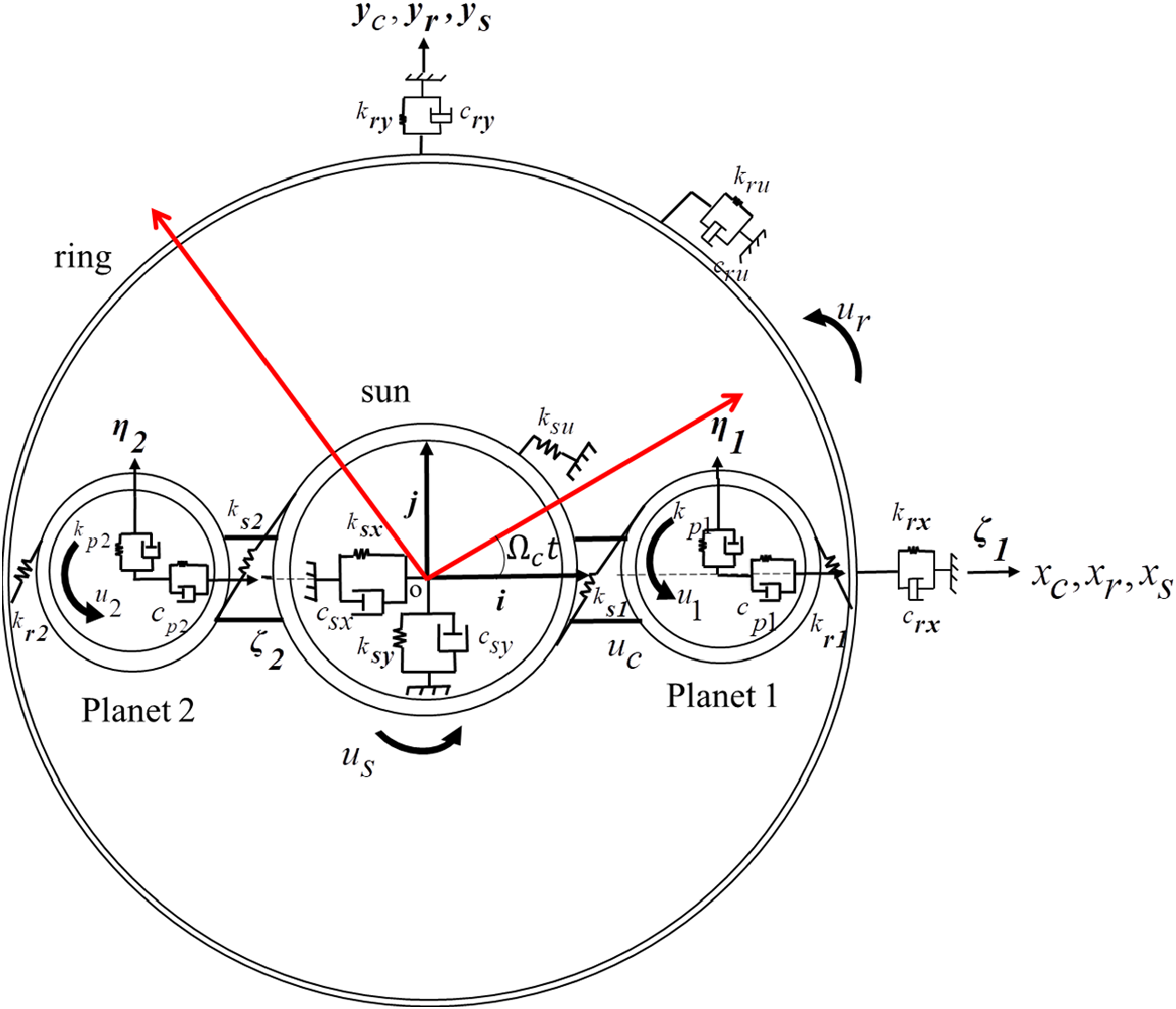
The equations of motion of the rigid bodies were obtained using a rotating frame of reference fixed to the carrier centre with origin
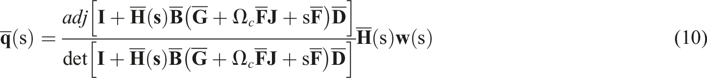
For pole placement, the second order equation of motion for the planetary gear system using a rotating frame of reference is written in the Laplace domain as according to Mottershead et al.
17
and Lin and Parker
4


The displacement vector is denoted by

The feedback control law using a rotating frame of reference is written as


The carrier and sun gear are denoted by subscripts c and s because the control forces were applied to one of them in each case.
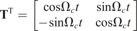
From Equation (4), the control force using a rotating frame of reference can be transformed into a fixed frame of reference using the transposed form of the transformation matrix


The closed loop inverse dynamic stiffness matrix is written as

The open loop inverse dynamic stiffness matrix is written as

Pre-multiplying Equation (9) by Equation (6), one obtains
The corresponding eigenvalues

*The corresponding eigenvalues

The method of pole placement to a planetary gear will be demonstrated in the next section.
Numerical examples of pole assignment
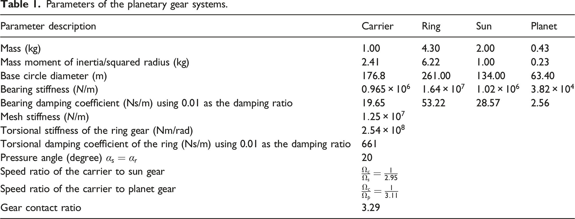
Parameters of the planetary gear systems.
Pole assignment to the sun gear
Two pairs of complex conjugate poles were assigned to the sun gear using two actuators supplying feedback control forces The control force being applied to the sun gear in the x and y directions. They are shown in blue arrows in both directions.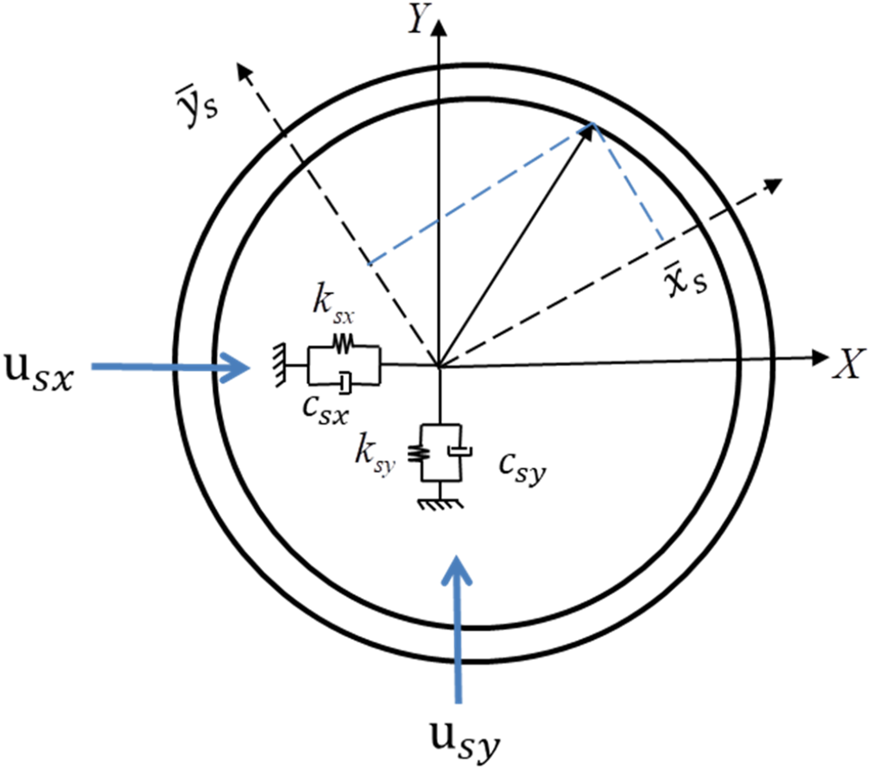
Two pairs of complex conjugate poles at
The actuator distribution matrix 
The open-loop inverse dynamic stiffness matrices are written as

The characteristic equation was solved using the ‘fsolve’ routine in MATLAB to determine feedback gains 
The result was validated using a state space representation written as: 
which yield the following closed loop poles obtained for a carrier speed of 100 rpm
The poles are the same as the closed loop poles assigned. The displacement per unit mesh excitation for both the horizontal and vertical directions are shown in Figure 3. Displacement per mesh excitation force of the sun gear in the (a) x and (b) y directions with and without control due to mesh excitation using a rotating frame of reference at a carrier speed of 100 rpm. The initial and the modified displacement per mesh excitation are plotted in red and blue respectively.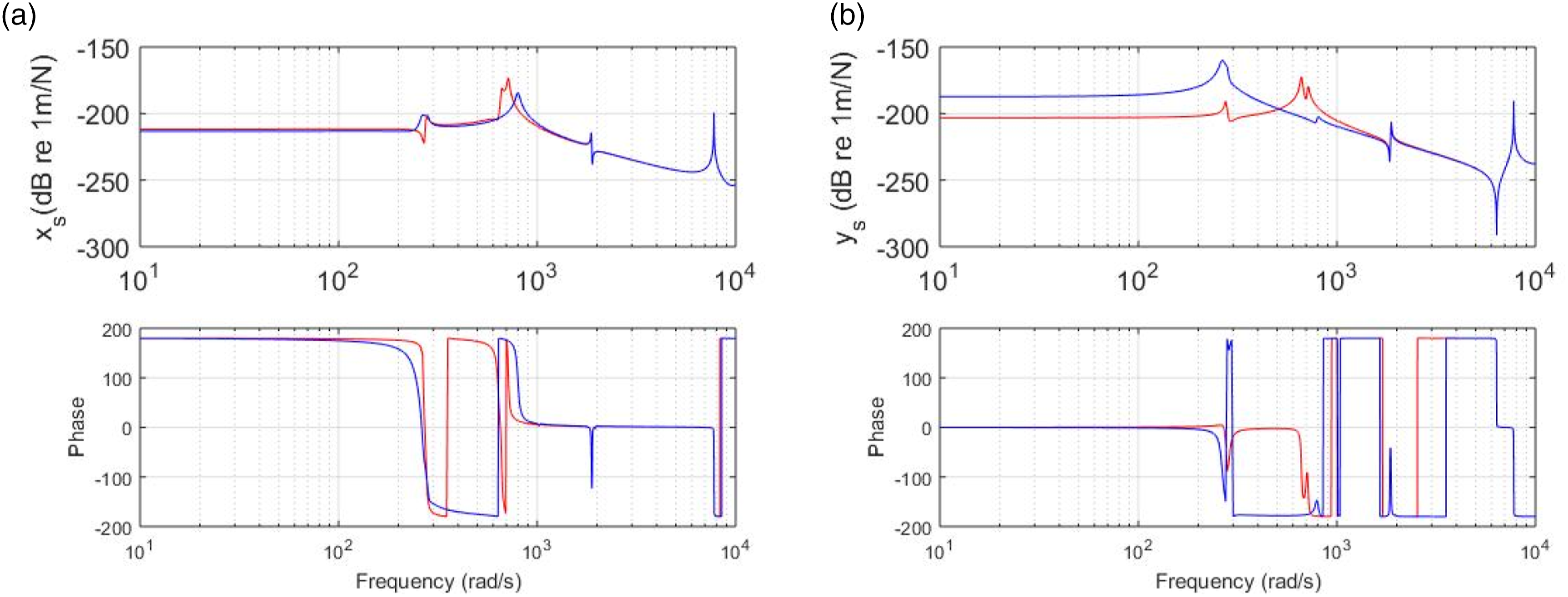
The result in Figure 3(a) which is the displacement of the sun gear in the horizontal direction, shows that a pole was shifted from
Figure 4 shows the three pairs of conjugate poles which were shifted. They are poles of the translational modes because the poles were assigned to the sun gear in the translational The s-plane showing the locations of the initial and the modified poles when the control forces were applied to the sun gear using a rotating frame of reference at 100 rpm.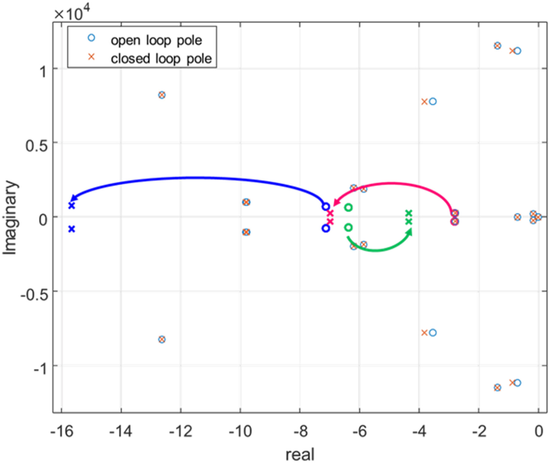
The control force per mesh excitation force (normalised) and absolute control force are shown in Figure 5 by blue and orange lines respectively. Control forces applied on the sun gear in both the (a) x and (b) y directions using a rotating frame of reference at a carrier speed of 100 rpm.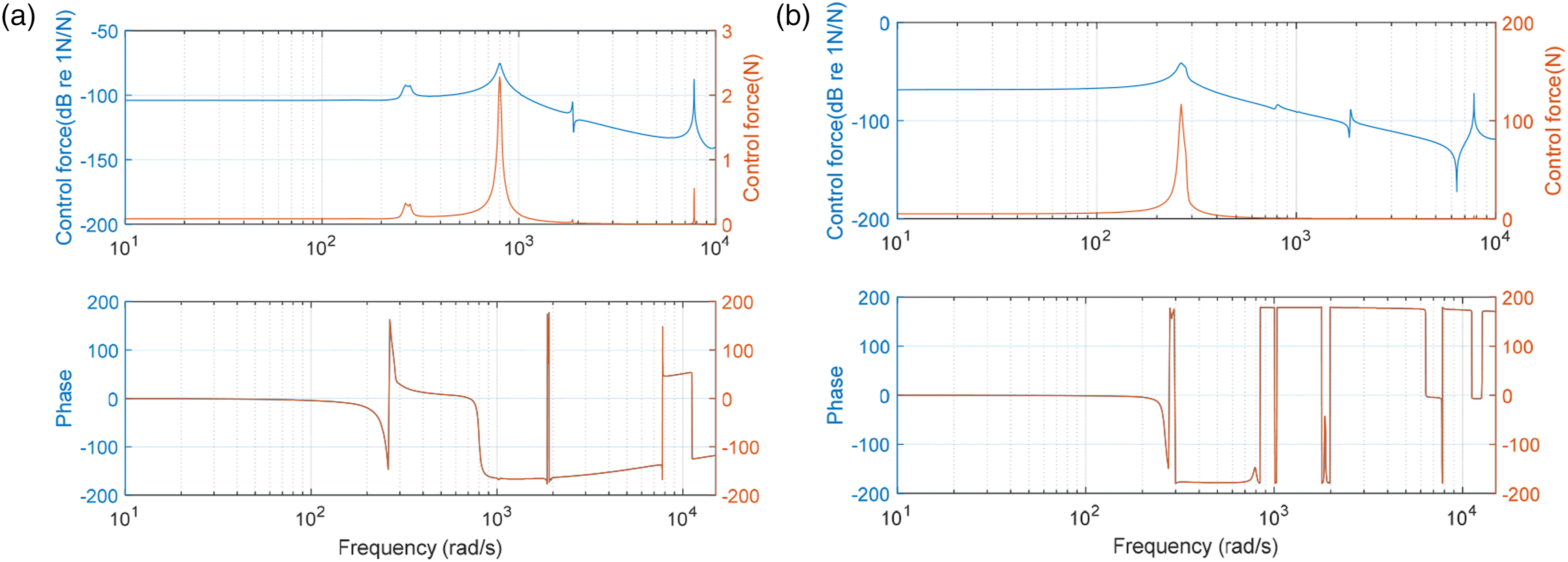
The control forces required depend on the control gains
Bobrovnitski
22
gives the expressions for both the real and imaginary parts of the complex power flow. The control power using a rotating frame of reference is determined by multiplying the control force by the Hermitian conjugate of velocity in a Laplace domain as written in Equation (14).
The active control power is the real part of equation (
In addition, the mean square control force using a rotating coordinate is also considered. This is given by
Although the mean squared force, active and reactive powers are shown in Figure 6, it is the active power that is the main interest in this study. This is because it gives the real active control power required to shift the poles from one location to another. Figure 6(b) shows the active control power required by the sun gear in both the x and y directions. Very small magnitudes of the active control power are required to shift the poles in both directions. (a) Mean square control force (b) Active control power (c) Reactive control power required by the sun gear in both the x (to the left) and y directions (to the right) using a rotating frame of reference when the rotational speed is 100 rpm.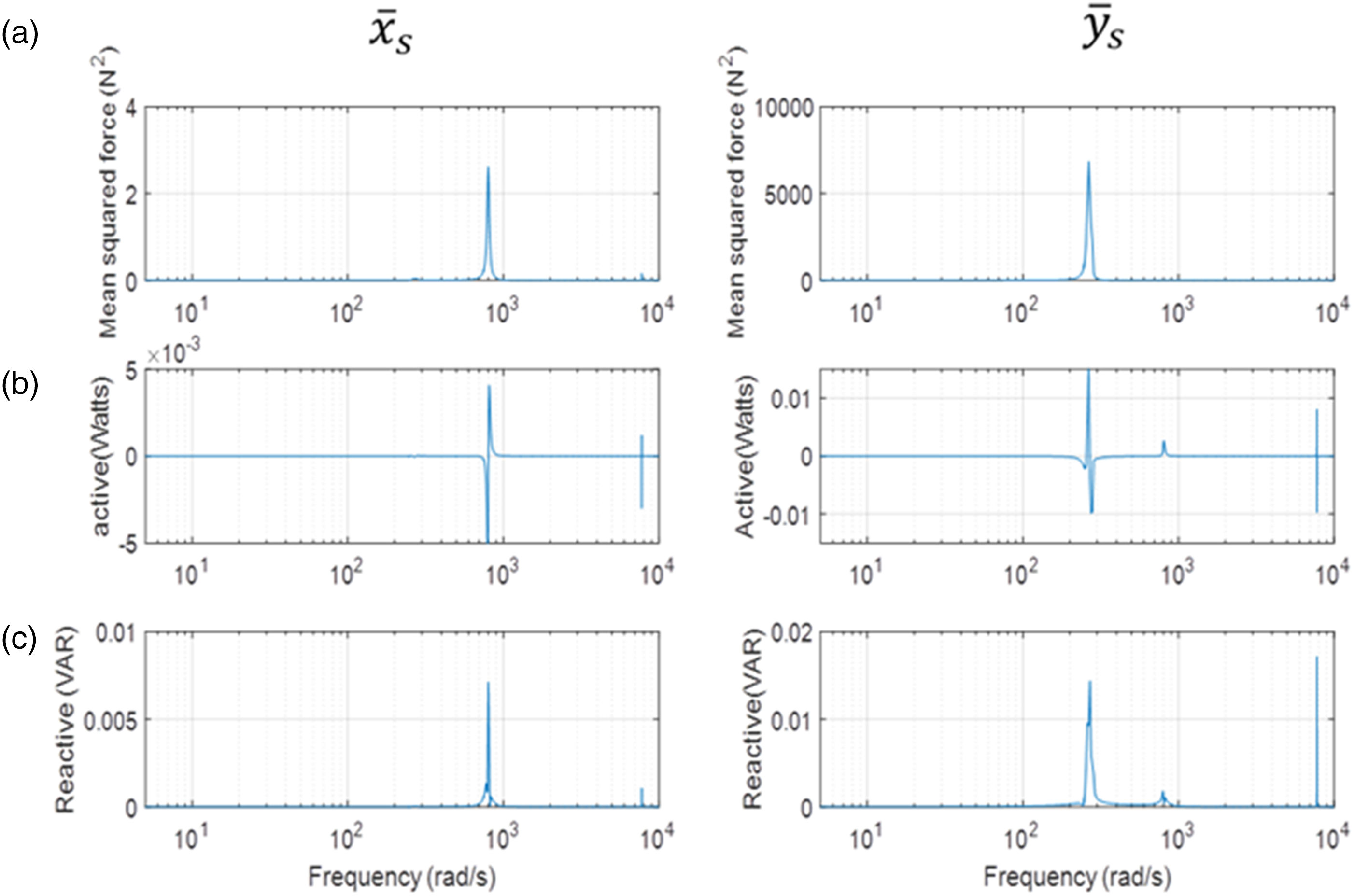
Pole assignment to the carrier
The method of pole placement was consequently applied to the carrier only in the 
The results were validated by using the state-space equation written in equation (13), and this yields
Figure 7(a) shows the displacement per mesh excitation of the carrier in x direction where the pole of the first excited translational mode is shifted from Displacement per mesh excitation of the carrier in the (a) x and (b) y directions with and without control due to mesh excitation using a rotating frame of reference. The initial and the modified displacement per mesh excitation are plotted in red and blue respectively.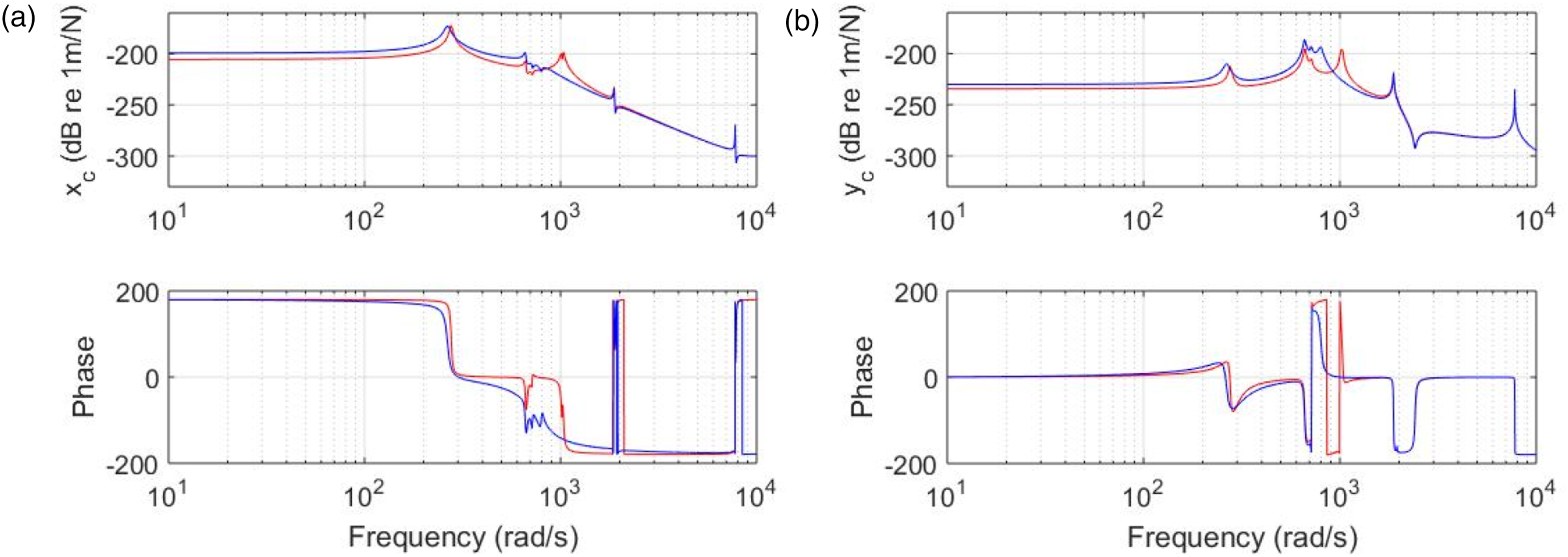
The conjugate poles, which were shifted after pole placement, are shown in Figure 8. The two assigned poles and other poles can be seen before and after modification. The magenta line shows the pole shifted from The s-plane showing the locations of the initial and modified poles when the control forces were applied to the carrier using a rotating frame of reference.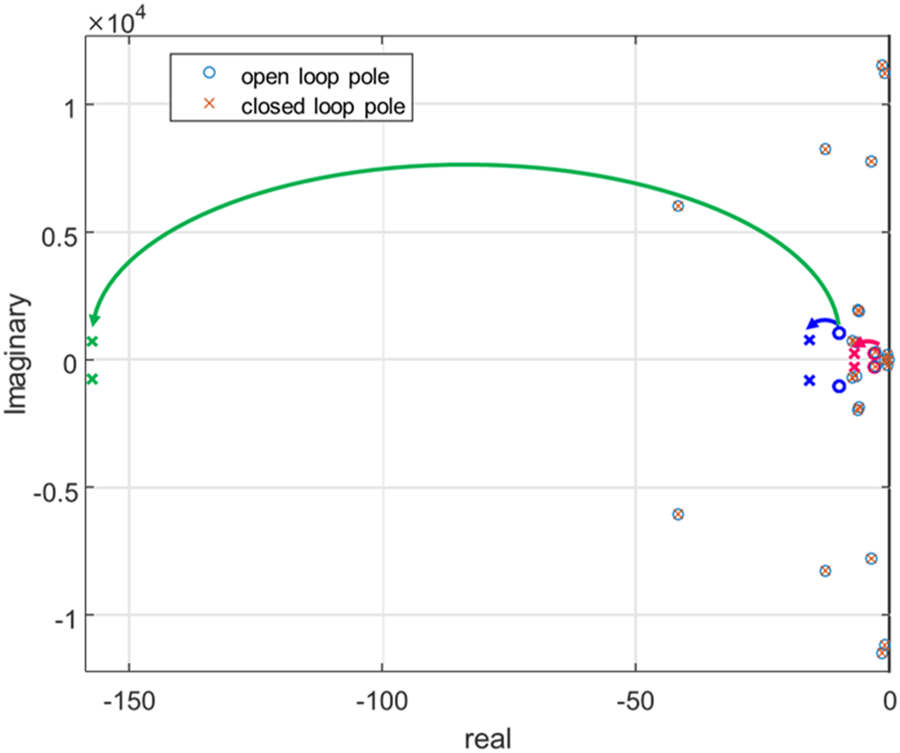
The normalised (blue line) and absolute (orange line) control forces are shown in Figures 9(a) and (b). A force of 15.6 N is required in the x direction to shift the pole from 276.75 to 265 rad/s, while a force of 1.04 N is required to shift the pole from 1023.7 to 800 rad/s in the Control forces applied on the carrier in both the (a) x and (b) y directions using a rotating frame of reference.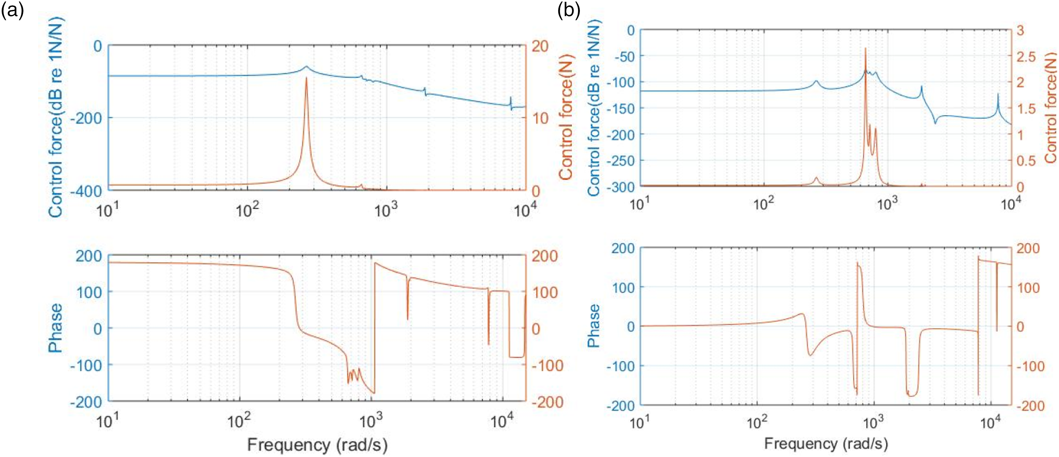
The active control power required by the carrier is relatively higher than that required by the sun gear in both the (a) Mean square control force (b) Active control power (c) Reactive control power required by the carrier in both the x (left hand side) and y (right hand side) directions using a rotating frame of reference at a carrier speed of 100 rpm.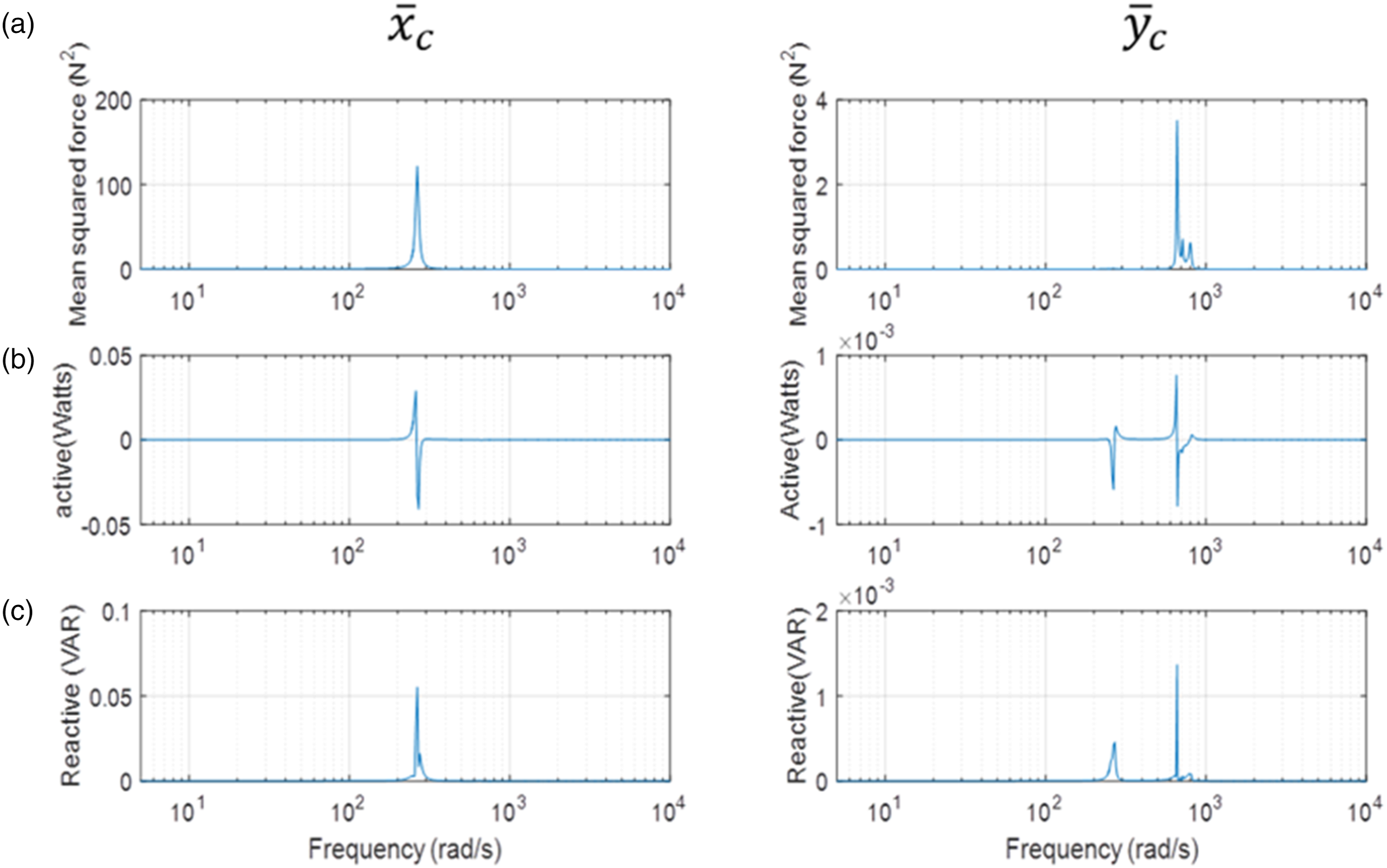
For a high margin between the open and closed loop poles, the control effort required to be applied to the sun gear is higher because it has higher support stiffness. This is not the case for the low margin between the open and closed loop poles, where the control effort required by the carrier is higher. Therefore, the optimal place to apply control in the planetary gear system considering the control effort required depends on the initial location of the poles and the desired final shifted pole location in the
It has been shown by numerical examples that the poles can be assigned and the control forces and powers can be obtained. This means a pole can be assigned using a rotating frame of reference where the accelerometers are rotating with the system at a particular carrier speed. However, since the actuators cannot rotate with the system in practice, so the control force and power required to shift the pole using a rotating frame of reference can be transformed using a fixed frame of reference for a more practical implementation. This is due to the fact that the accelerometers and actuators are typically stationary when using a fixed frame of reference.
Effect of the carrier speeds on the closed loop poles at constant gains
The conjugate closed loop poles and their corresponding control gains at different rotational speeds.
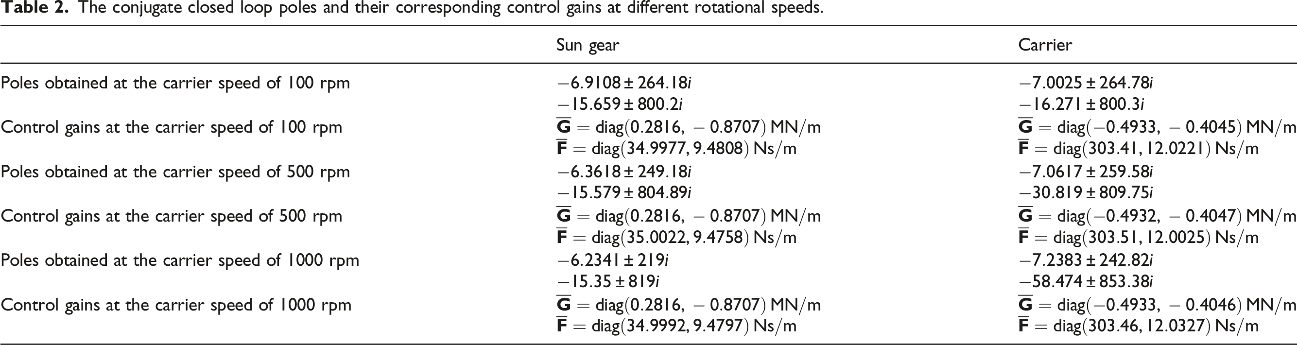
The closed loop poles obtained, which produce approximately the same feedback gains, are not the same at the three different speeds. For instance, the two conjugate closed loop poles for sun gear at 100, 500 and 1000 rpm are different for approximately the same gains (Table 2, column 2). It shows that the imaginary part of the first pole changed from 264.18 to 249.18 when the speed was increased from 100 to 500 rpm. This later changed from 249.18 to 219 rad/s when the speed was further increased from 500 to 1000 rpm. This is the same for the second pole which changed from 800 to 804.89 and subsequently to 819 rad/s. However, it shows that the increase in speed does not have a significant effect on the real side of the poles which determines the level of damping in the system. The same thing is applicable to the carrier except that the increased speed leads to significant change in the real side of the second closed loop pole.
The influence of the rotational speed on the closed loop poles assigned to the carrier is studied considering constant gain at 1000 rpm. Figure 11 shows clearly the results from 0 to 1000 rpm. Figure 11(a) shows that for the first pole at Effect of the carrier speed on the poles for constant feedback gains at 1000 rpm when the poles were assigned to the carrier. The blue solid line indicates the first pole while the orange dashed line indicates the second pole. (a) Real part of the poles (b) Imaginary part of the poles. The effect of the rotational speed on the control gains at constant poles assigned to the sun gear. (a) gains 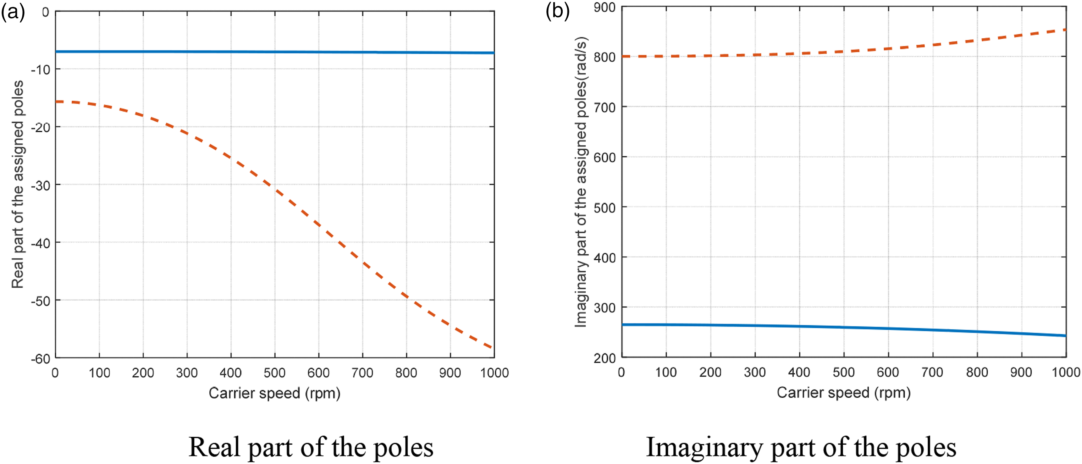
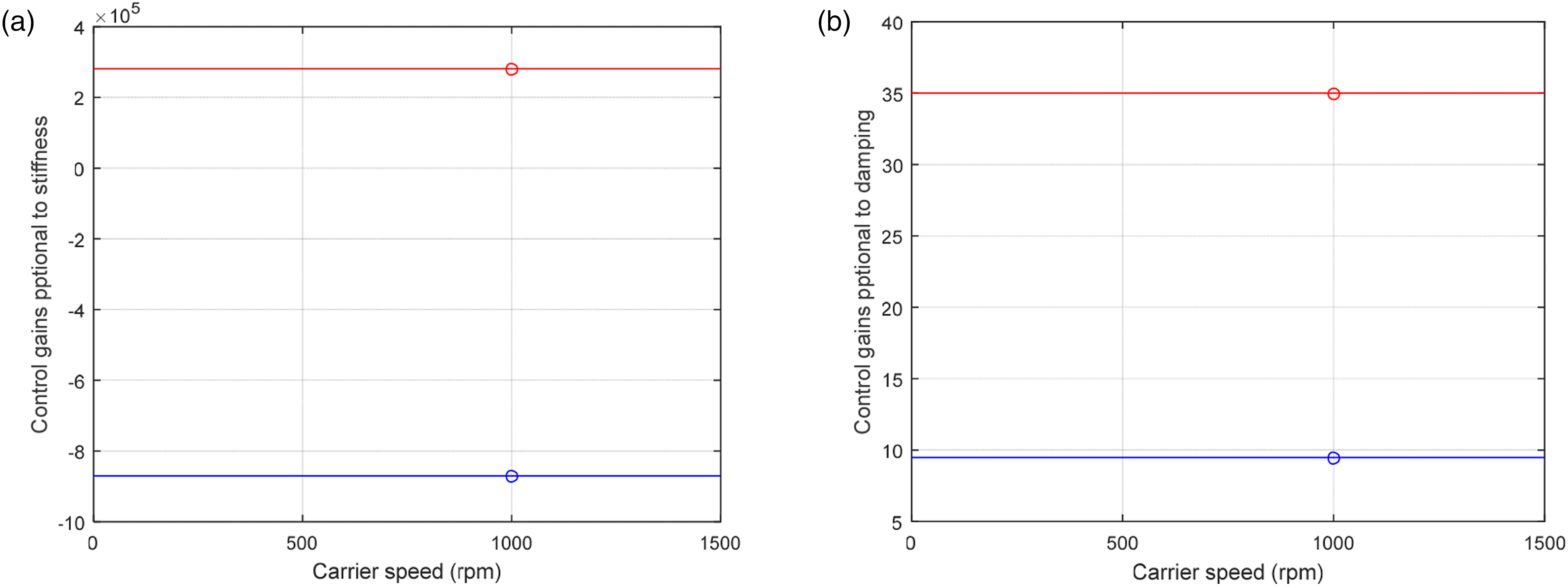
Effect of the rotational speed on control gains for constant specified closed loop poles
This section focuses on the effect of the rotational speed on the control gains. In this case the closed loop poles at 1000 rpm were fixed at their locations. Figure 12 shows that the gains are not changing when varying the rotational speed above or below 1000 rpm. This implies that the performance of the controller can still be guaranteed when varying the rotational speed with the closed loop poles remaining invariant. Therefore, one can predict that pole placement method is a robust method considering the insensitivity of the gains to the rotational speed.
Discussion
In this study, the theory of pole placement has been extended to the vibration control of planetary gear such that the required active control force and power can be predicted considering the rotational speed of the system and the feedback gains (Figures 5, 6, 9 and 10). The equivalent active control force and power required for instance at 500 and 1000 rpm can then be determined by transforming to a fixed frame of reference for a practical implementation. This is achievable because the control system was designed such that the control force and power required can be obtained at any rotational speed.
This investigation has numerically demonstrated how a pole placement method can be used to actively control the vibration of a planetary gear system. The controller was designed such that the closed loop poles can be assigned using either fixed or rotating frames of reference. Therefore, for a rotating planetary gear system, the feedback gains can be determined at a particular rotational speed using a rotating frame of reference and then transformed to equivalent gains in a fixed frame of reference for implementation.
The control force and power required (which depend mainly on the active stiffness and damping) can then be determined at each frequency, therefore the kind of actuator required for the control experiment can be known. The numerical predictions show that the assigned poles of lower frequencies corresponding to translational modes are shifted to avoid resonance with the addition of damping to reduce the response in both x and y directions. The predicted control forces required for the method are small; therefore, actuators with low control force will be suitable for practical implementation.
In addition, for the same poles assigned to the sun gear and carrier, it shows that sun gear requires more control force and power. The active bearing stiffnesses added in each case are responsible for this phenomenon. Although the control force and power depend on the active stiffness and damping added, but for a system like planetary gears whose bearing stiffness is significantly high compared to the support damping, active stiffness mainly dictates the values of the control forces required. For instance, the active stiffness added to the sun gear in x direction is 0.2816 MN/m while 0.5 MN/m was removed from the carrier in the same direction when the same poles were assigned. The active damping added to sun gear in the same direction is 35 Ns/m while that of the carrier is 303.46 Ns/m. With more damping added to the carrier in this direction, the control force required is lower than that required to be applied to the sun gear.
Also, this study unlike previous studies shows how the control force and power required to control the vibration of the system can be obtained in a rotating frame of reference. This force can be subsequently transformed to equivalent forces in fixed frame of reference for a practical implementation. Considering the current technology, sensors and actuators cannot easily rotate with the planetary gear components in practice. Montague et al.
14
show that the control force can be transmitted to the gear shaft through the bearings which are fitted in adaptors (stators). Similarly for this study, the actuators can be mounted on the sun gear bearing adaptor in x and y directions in order to apply the control force (Figure 13). This can also be applied to the carrier through its bearing adaptor. Planetary gear system showing locations where sensors and actuators can be attached on sun and carrier shafts.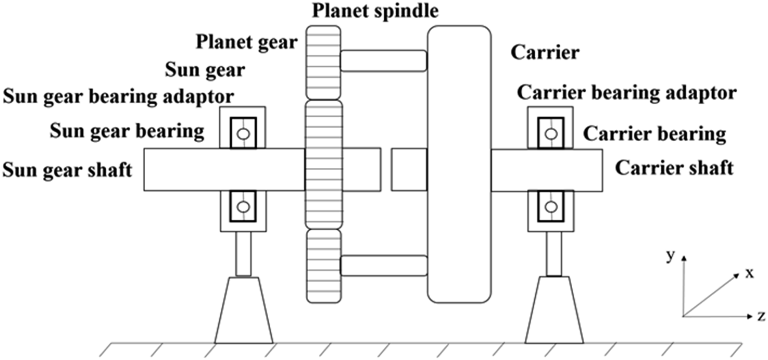
For the case of active control method by velocity feedback, it is different from pole placement. This is because the feedback gains are not assigned to shift the poles of the system to particular locations in the s-plane, unlike the pole placement method. Instead, velocity feedback primarily is applied to increase the dissipation. The poles in this case may not be shifted to desired locations and still be an issue.
The main source of vibration in gear train with low contact ratio is the variation in mesh stiffness which occurs when the number of pairs of teeth in mesh is changing. This parametrically excited vibration can be effectively reduced using a high contact ratio gears. Although, some papers have also addressed passive control method like tooth profile modification and mesh phasing.1,6,7,8,10,12 In many cases, these methods of passive modifications may be difficult to achieve because it may require design modifications and further manufacturing work. This may also take more time to achieve and may not be cost-effective. Therefore, another method that can be used is active vibration control as proposed in this work, where some modern devices (actuators, sensors, controller, etc.) are used to mitigate the planetary gear system vibration.
Conclusions
The theory of pole placement in active vibration control has been extended to control the vibration of planetary gear in this study. This pole placement method considers output feedback and this was presented and numerically implemented. The controller was designed such that the closed loop poles can be assigned using a rotating frame of reference to control vibration of a planetary gear system. The feedback gains, active control forces and powers can be obtained at any rotational speed using a rotating coordinate. These control parameters can then be transformed into a fixed frame of reference to obtain their equivalents for practical implementation. The insensitivity of the control gains to the rotational speed was demonstrated showing the robustness of the method. First and foremost, the same poles were assigned to the sun gear only and subsequently the carrier in the x and y (translational) directions. Three open loop poles corresponding to translational modes out of eight were shifted with two control forces applied either on the carrier or sun gear. This shows that the method is suitable to actively control the mesh vibration of a planetary gear system.
The study shows that for this vibration control method, the control forces required by the actuators are not high; hence, actuators with low control forces and displacement will be suitable for practical implementation.
The optimal places to mount the actuators in order to apply control force on either the carrier or the sun gear was determined considering the control power required after assigning same conjugate poles on them. For comparison, the control power required by the sun gear to shift the poles is higher because the active stiffness required to be added is higher. Therefore, the optimal place to apply control force depends on the control force and power required to shift the poles from one location to another. For the same conjugate poles assigned to the sun gear and carrier in this study, the optimal place to apply control force is the carrier. This is because the control force required to shift the pole of the system in order to avoid resonance is relatively lower when poles are assigned to the carrier.
Footnotes
Acknowledgements
The authors would like to appreciate the Tertiary Education Trust Fund (TETFUND), Nigeria, Institution of Mechanical Engineers, United Kingdom and University of Southampton, United Kingdom for studentship support.
Declaration of conflicting interests
The author(s) declared no potential conflicts of interest with respect to the research, authorship, and/or publication of this article.
Funding
The author(s) disclosed receipt of the following financial support for the research, authorship, and/or publication of this article: This work was supported by the Tertiary Education Trust Fund and University of Southampton, United Kingdom.