
Abstract
Considering the comprehensive effect of the internal non-inertial system of planetary gear transmission (PGT) and external non-inertial system of the body, combined with the modified Heywood formula and Hertz formula, a calculation model for the dynamic bending stress and contact dynamic stress of the PGT in a non-inertial system (NIS) is proposed. The stress non-inertial coefficients (KNI) describing the influence of the additional effects on the dynamic stress in the non-inertial system are defined. Additionally, the variation law of non-inertial coefficients under two typical non-inertial conditions of variable-speed horizontal flight and somersault motion was studied. The effect of gear installation and manufacturing errors on the non-inertial coefficients under two maneuvering conditions was analyzed. The results indicated that non-inertial coefficients increase with an increase in the maneuverability of the body, and the variable-speed horizontal flight and somersault motion have significant effects on the changing trend of non-inertial coefficients with the gear installation and manufacturing errors. Compared with the gear error, the effect of the NIS has a significant influence on the non-inertial coefficients.
Introduction
In general engineering dynamics, the earth can be approximated as an inertial system, and a reference system that performs variable-speed linear motion or curvilinear motion relative to the inertial reference system of the earth is called a non-inertial system (NIS). 1 An aircraft changes the flight trajectory by changing the acceleration, realizing several maneuvers such as hovering, climbing, and rolling. It is a typical NIS. Planetary gear transmission (PGT) is widely used in aviation owing to its high transmission ratio, high reliability, and compact structure.2,3 The planetary gear rotates while revolving with the planet carrier; therefore, the PGT is a NIS, that is, an internal non-inertial system (INIS). When the PGT moves in space following the body, it is affected by the external non-inertial system (ENIS); that is, the components of the PGT are under the action of the dual NIS. For aviation PGTs that work under extreme conditions such as high speed, heavy load, and high vibration, the NIS has a significant impact on its stress, deformation, gear meshing, and other dynamic behaviors. Therefore, it is necessary to study the additional effect of the NIS of maneuvering flight on the PGT, and to ensure good environmental adaptability as well as safe and reliable operation of the PGT in the transient posture and arbitrary motion path.
The bending dynamic stress of the gear tooth root and the contact dynamic stress of the gear pair are the direct reflections of the load-carrying capacity of the gear, as well as the direct cause of fatigue failure, such as gear tooth fracture, tooth surface pitting, and tooth surface spalling. The additional effects of NIS as well as gear installation and manufacturing errors may significantly change them, which poses a major threat to the safety and reliability of an aircraft. Therefore, it is crucial to improve the load-carrying capacity of PGT in a highly maneuverable NIS that analyzes the additional effects of typical NIS environments such as variable-speed horizontal flight and somersault motion on the dynamic stress of the PGT.
In the existing literature, the study of dynamics in the NIS is mainly concentrated in the engine rotor-bearing system. Soni et al. 4 studied the vibration response of a magnetic suspension rotor system during pitch, roll, and yaw, and they proved the superiority of the new control method in the stability control of a magnetic suspension rotor system under moving conditions by comparing the system stability during motion. Dakel et al. 5 established a single-rotor shafting finite element model based on the Timoshenko beam element. By deriving the Lagrangian equation of motion, they established that the basic rotation not only caused changes in the system parameters but also generated additional external force vectors. Basic translational motion only generates additional force vectors. Using rotor stability diagrams, Campbell diagrams, steady-state response, and motion trajectories, they studied the dynamic characteristics of two different rotor configurations: symmetric and asymmetric. Duchemin 6 used a multi-scale method to study the stability of the rotor system when performing sinusoidal rotation and perform experimental verification. Yang et al. 7 studied the nonlinear response of a rigidly supported cracked rotor system under maneuvering flight conditions. Three ways for rotor responses going to chaos were summarized. Han et al. 8 established a dynamic model of an aero-engine single-rotor shafting-ball bearing system based on the Timoshenko beam element, simulated the flight maneuver state as an additional damping matrix, stiffness matrix, and load vector, and they studied the multi-period, irregular, and transient vibrations. The results indicated that both the beginning and end of the maneuvering flight could cause a transient response. As a nonlinear system with self-excitation characteristics, the gear transmission system exhibits significant differences in the dynamic behavior of the engine rotor system. Currently, research on the dynamics of gear transmission systems under NIS is only in the preliminary stage. Parker9–11 conducted a series of studies on parallel shaft gear transmissions, including modeling methods, internal and external excitation, structural parameters, and their corresponding vibration behaviors. Han et al. 12 deduced the motion equations of the spur gear pair system under the excitation of basic motions such as roll, pitch, and yaw based on the energy theorem and Lagrangian principle, and they discussed the effect of various basic rotations on the amplitude–frequency response of the gear. Qiu et al. 13 deduced the translation-torsion-axial dynamics model of the PGT under the basic pitching motion, and they studied the effect of the additional damping, stiffness, and external force excitation caused by the pitching motion on the dynamic response of the system. The results indicate that the motion of the body introduces more excitation frequencies to increase the system vibration and increase the risk of system resonance. Wei et al.14–16 considered the comprehensive influence of the INIS and ENIS, and they constructed a kinematic and dynamic model of the gear system in any space motion state of the body in the NIS. They deduced the time-varying influence function of gravity on the carrier in the NIS, derived the additional inertial force and the additional gyro moment, and initially revealed the law of motion change and dynamic response of the transmission system under the condition of the NIS. In addition, multi-excitation and nonlinear factors are being considered more and more comprehensively to capture their coupling effects under NIS conditions.17,18
For gear dynamic stress, Kahraman et al.19–21 studied the effect of the thickness of the ring gear flange, the number of planetary gears, and the error of pinholes on the time-domain history of the dynamic stress of the tooth root of the ring gear through experiments. Cornell 22 obtained the modified Heywood formula by simplifying the Heywood formula, and proved the modified formula by comparing different pressure angles, transmission ratios, tooth numbers, and load contact positions corresponding to the tooth root dynamic stress test, finite element, and analytical results. Li et al. 23 analyzed the tooth load, load sharing rate, contact stress, root bending stress, transmission error, and mesh stiffness of spur gears, and they discussed the effect of the contact ratio on the gear strength and basic performance. R. Ramadani et al.24,25 discussed the influence of a gear body structure on gear vibrations induced by meshing, and a new precise closed loop test rig was designed and produced to measure experimentally vibrations. Zhang et al. 26 established a large-load marine helical gear meshing finite element model based on the explicit dynamics finite element method, simulated the dynamic stress changes of the helical gear under various working conditions, and analyzed the effect of the working condition changes on the dynamic stress. The results indicate that the speed and center distance errors of the helical gear pair have a significant influence on the dynamic stress of the tooth root. He et al. 27 proposed a numerical model of intersecting bevel gears to evaluate the dynamic stress distribution and dynamic transmission error, and they calculated the dynamic contact characteristics of involute and non-involute bevel gears using the three-dimensional dynamic contact finite element method. Zhou et al. 28 developed a gear test bench that can wirelessly measure the dynamic tooth root stress of a light-load spur gear drive and wirelessly send or receive the tooth root strain, speed, and torque signals of the gear shaft. Tsai and Ye 29 proposed a PGT gear tooth load contact analysis method and studied the effect of the torsional stiffness of the sun gear and planet carrier on the contact stress distribution. Wang et al. 30 used the modal superposition and Newmark beta time integration methods to calculate the dynamic characteristics of the ring gear, and they verified the validity of the calculation method by comparing it with the experimental results.
This study establishes a dynamic stress calculation model of the PGT in a NIS and defines a parameter describing the influence of additional effects on the dynamic stress of gears under a motorized NIS—the stress non-inertial system coefficient (KNI). In addition, we conducted an in-depth study on the influence of gear installation and manufacturing errors on the stress non-inertial coefficients under the two typical non-inertial conditions of the airframe in variable-speed horizontal flight and somersault motion.
Dynamic model of planetary gear system in a non-inertial frame
Coordinate system setting
Considering that the internal meshing position of the gear system rotates with the planet carrier, the dynamic model of the PGT is established in the planet carrier follow-up coordinate system, and the kinematic analysis of each component is performed in the multi-coordinate system. As shown in Figure 1(a), all the degrees of freedom of the sun gear shaft, ring gear, and translational degrees of freedom of the planet carrier shaft are defined in the planet carrier follow-up coordinate system (INIS), oc-xcyczc. All degrees of freedom of the planetary gear and pin are defined in the planetary carrier follow-up coordinate system (the origin is at the center of the planetary gear), op-ξηzp. The torsional degrees of freedom, θc, of the planet carrier and all degrees of freedom of the housing are defined in the coordinate system o0-x0y0z0. As shown in Figure 1(b), body motion is defined in the body follow-up coordinate system, o1-x1y1z1. The ground fixed coordinate system, O-XYZ, is used to describe the rotation of the carrier around itself and the change in spatial position and posture. Here, o1 represents the center of gravity of the aircraft; the flying direction of the aircraft is the same as vertical axis o1y1; axis o1z1 is perpendicular to the vertical axis o1y1, and the direction is vertically downward; horizontal axis, o1x1, is perpendicular to axis o1y1 and axis o1z1; each axis of coordinate system o0-x0y0z0 is parallel to the corresponding axis of coordinate system o1-x1y1z1. Coordinate systems of the system. (a) Gear rotor system (b) Housing.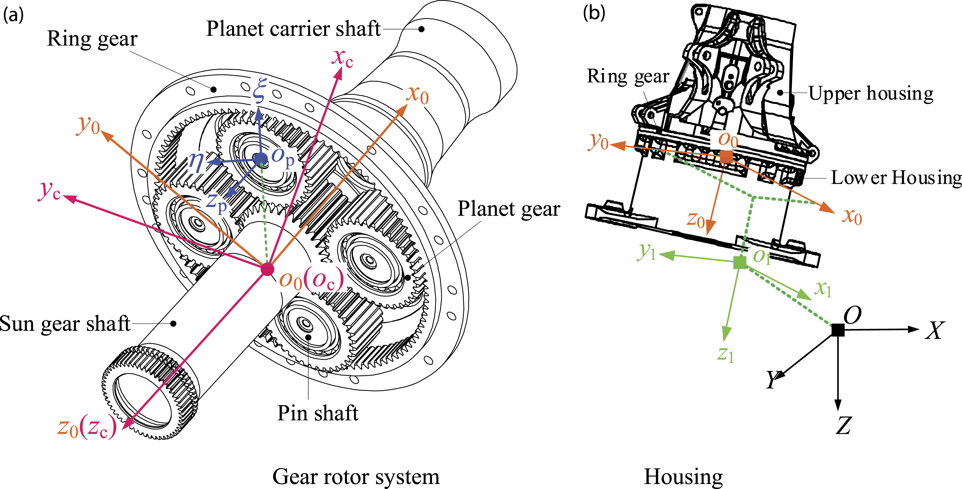
Kinematics analysis in NISs
Central component
The sun gear, ring gear, and planet carrier are the central components. For the sun gear shaft, the coordinate system is shown in Figure 2(a) when only the INIS conditions are considered. Node Ms represents the real-time position of the sun gear shaft node. The radius vector of moving point Ms in coordinate system oc-xcyczc is Coordinate system of sun shafting under NIS. (a) Internal NIS (b) Internal NIS (node axial distribution). (c) External NIS for maneuvering flight.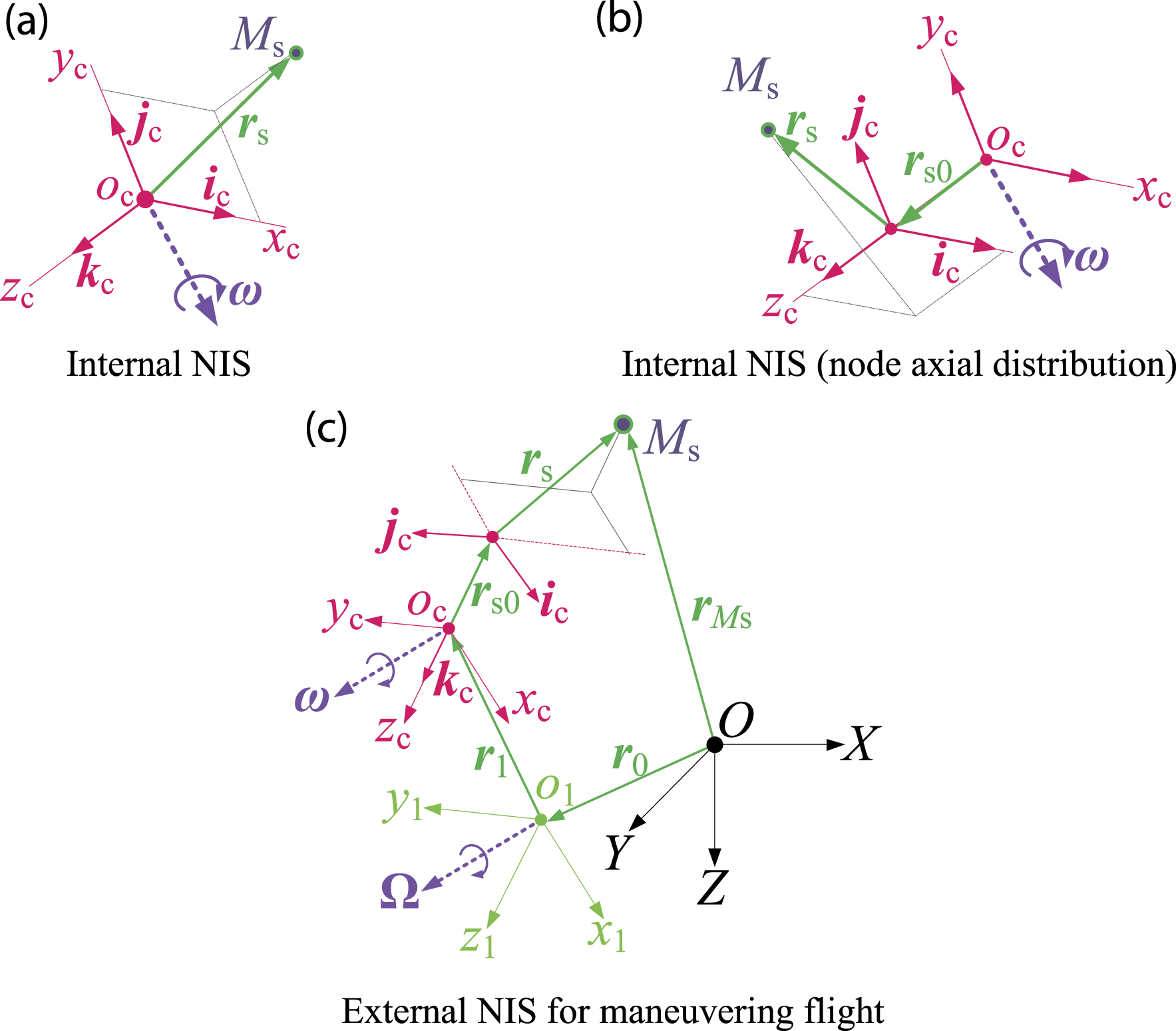
As shown in Figure 1, when the node finite element method is used to model the shaft system, the nodes of the sun gear shaft are distributed along the direction of its axis. Therefore, the sun shaft axis node Ms in coordinate system oc-xcyczc has a radius vector of
The second derivative of


Because

The planet carrier shaft and the sun gear shaft belong to the same central component, and the node settings are similar; therefore, their absolute acceleration equations are similar. Conversely, the ring gear does not have an initial radius vector because it has only one node in the axial direction. Therefore, when only the INIS conditions are considered, the absolute acceleration of the ring gear node is similar to that in equation (4).
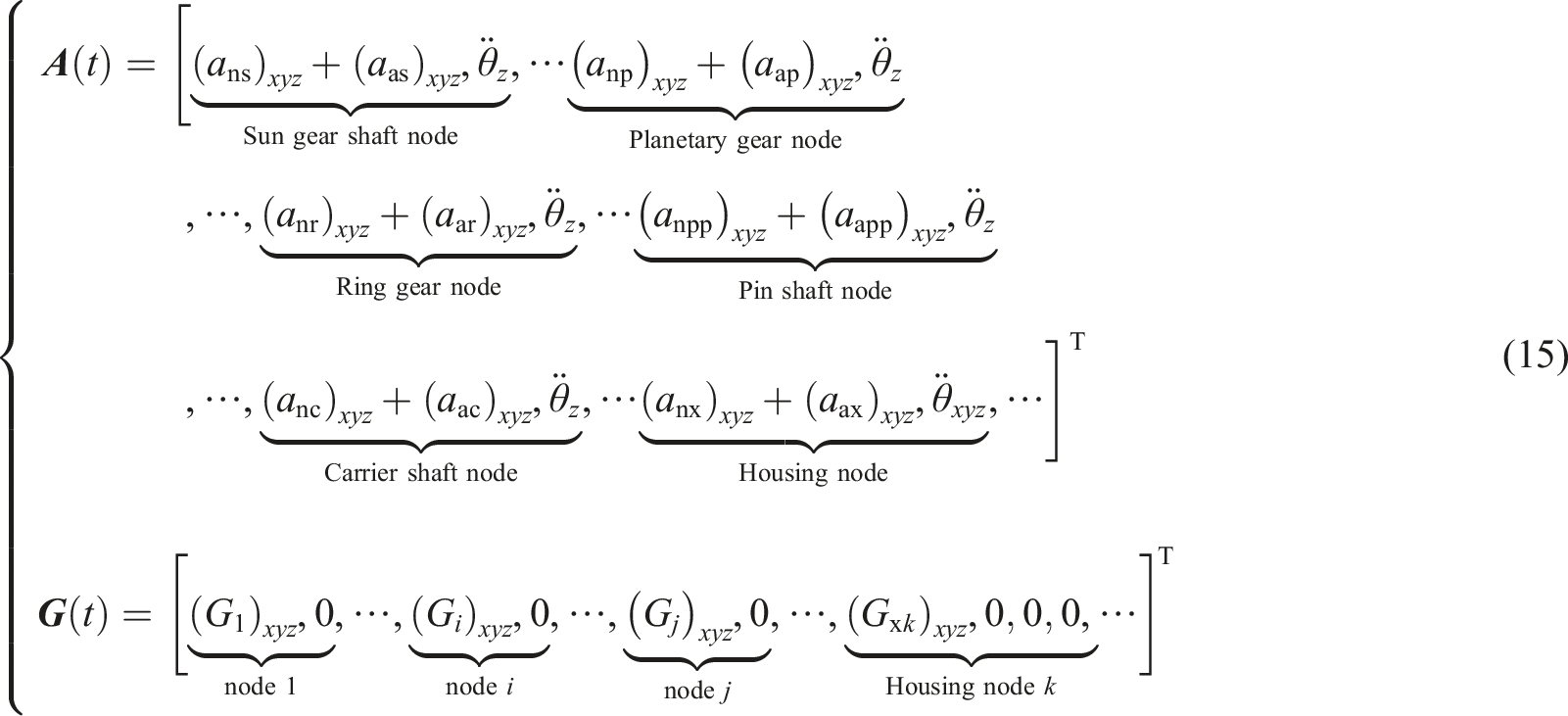
In contrast, according to Figure 2(c), considering the additional effects of the ENIS conditions of maneuvering flight, the radius vector of the sun gear axis node Ms in the ground fixed coordinate system O-XYZ is

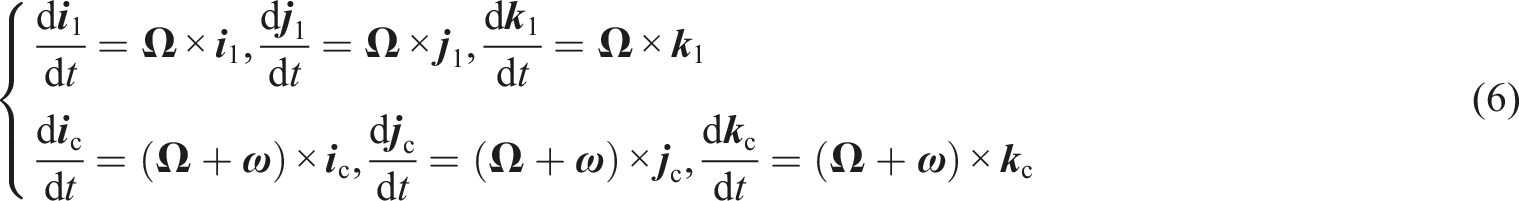
The derivative of the unit vector of o1-x1y1z1 and planet carrier follow-up coordinate system o-ξηzp with respect to time t is given according to equation (6), where
Taking the second-order derivation of

Similar to the case of considering only the INIS, the coordinate system of the planet carrier shaft node and the absolute acceleration additional items under the ENIS are similar to the sun shaft axis node. The additional items of absolute acceleration of the ring gear and planet carrier shaft nodes are given according to equation (8) and equation (9), respectively, where


Planetary gears and pin shaft
In contrast to the central component, the degrees of freedom of the planetary gears and pin shaft nodes are defined in the planetary carrier follow-up coordinate system, op-ξηzp. Considering the planetary gear, as shown in Figure 3, planetary gear node Mp is located on the equivalent base circle of the planet carrier. Its initial radius vector Coordinate system of the planet under NIS. (a) INIS (b) ENIS for maneuvering flight.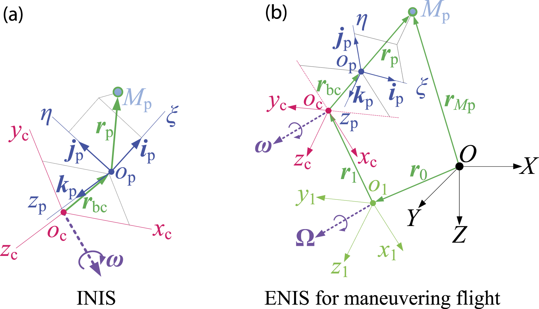
When only INIS is considered, the radius vector of the moving point, Mp, in coordinate system op-ξηzp is

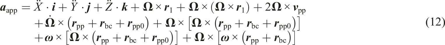
Compared with the planetary gears, the pin shaft nodes are axially distributed along the opzp direction of their axis; therefore, moving point Mpp has an initial radius vector
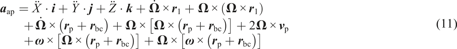
According to Figure 3(b), the radius vector of the planetary gear moving point Mp in fixed system O-XYZ is
System-level dynamics model
The author has established a detailed PGT dynamics model,
8
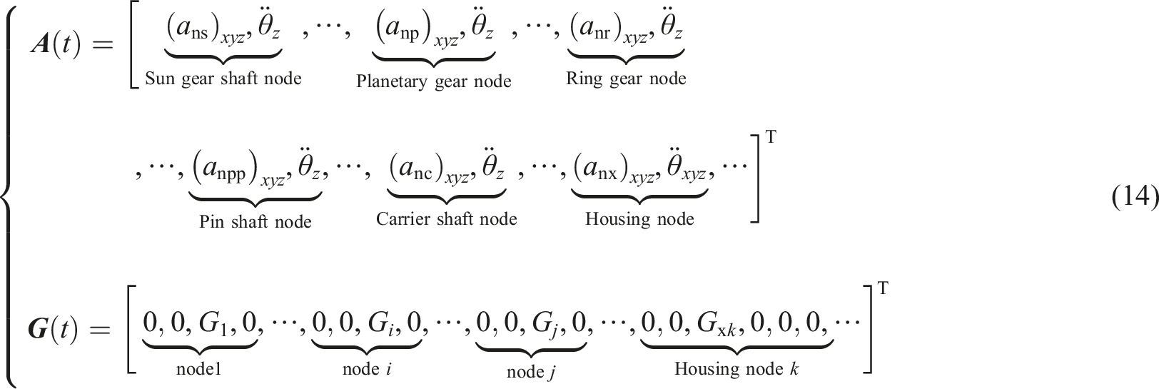
using the nodal finite element method and poly condensation technology to model the dynamics of the shafting and housing structures. Thereafter, the shafting and casing structures were coupled to establish a system-level dynamics model. The coupling dynamics equations of the system are as follows:

When only considering the INIS conditions,
Dynamic stress calculation model
Solving equation (13) yields the meshing force, Fmj, at any meshing position j. According to equation (16), the load distribution coefficient, Lsf
kj
, between the teeth of the tooth pair k (k = 1, 2) at meshing position j in the ideal meshing state can be obtained, where K
kj
represents the meshing stiffness of the tooth pair k at meshing position j. Thereafter, the meshing force of tooth pair k at meshing position j is F
kj
= Lsf
kj
· Fmj. Finally, the modified Heywood formula
14
in equation (17) and the Hertz contact stress formula in equation (18) are used to calculate the dynamic root bending stress and dynamic contact stress, respectively.


In equation (17) and equation (18), σFkj, σHkj, and ρ
kj
represent the maximum dynamic bending stress, dynamic contact stress, and comprehensive curvature of tooth pair k at meshing position j, respectively.
As shown in Figure 4, for an external gear whose basic parameters are known, the base circle radius, Rb, pitch circle radius, Rp, pitch circle pressure angle, α, pitch circle tooth thickness, sp, pitch circle to line of action, S, tooth root circle radius, Rr, and root fillet radius, rf, can be obtained. Thus, the load angle α
j
, tooth thickness hL, tooth thickness hf at the peak position of the tooth root stress, and height lf can be obtained according to equations 19–22. Schematic diagram of the modified Heywood formula parameters of the external gear.


Stress non-inertial system coefficient
The additional effect of the NIS has a significant impact on the dynamic stress of planetary gears. To quantify the influence of the additional effects of NIS on the dynamic stress of train gears to facilitate the design of the PGT, the stress non-inertial system coefficient (KNI) is defined, including the bending dynamic stress non-inertial system coefficient KNIFw2 and the contact dynamic stress non-inertial system coefficient KNIHu. In equation (29), “NI” represents a non-inertial system, w2 = s, p, pr, r, and “pr” represents the planetary gear that participates in internal meshing.
Take KNIFs as an example, which is the non-inertial coefficient of the bending dynamic stress of the sun gear, to illustrate the specific calculation method. First, the minimum value of the root mean square (RMS) value of the bending dynamic stress at the root of the sun gear in INIS,
Non-inertial coefficients of stress during variable-speed horizontal flight and somersault motion
Variable-speed horizontal flight
Variable-speed horizontal flight is the most common maneuver. As shown in Figure 5, the airframe flies in a straight line along the OY direction with acceleration ae. “ae < 0” and “ae > 0” indicate decelerated horizontal flight and accelerated horizontal flight, respectively. Schematic diagram of plane flight with variable speed.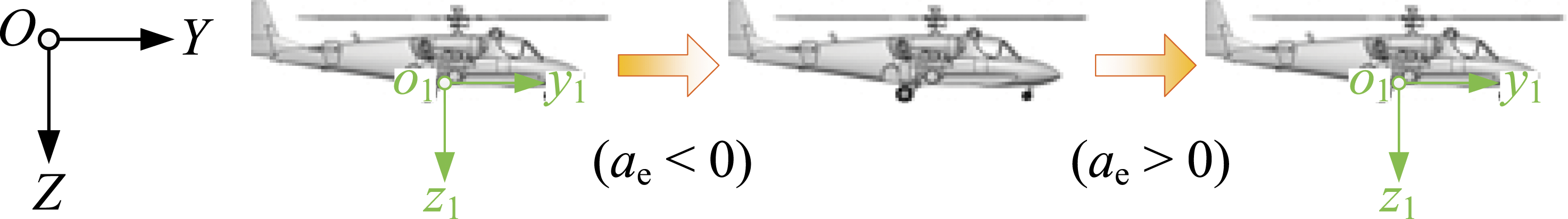
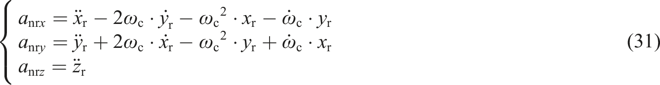
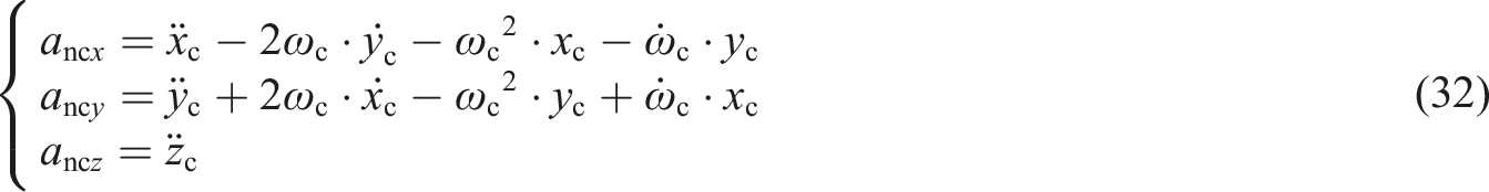
When only the INIS conditions are considered, the absolute acceleration equation of the sun gear shaft node is given according to equation (30).

The absolute acceleration equations of the ring gear and planet carrier shaft nodes are the same as those of the sun gear shaft nodes, according to equation (31) and equation (32), respectively.
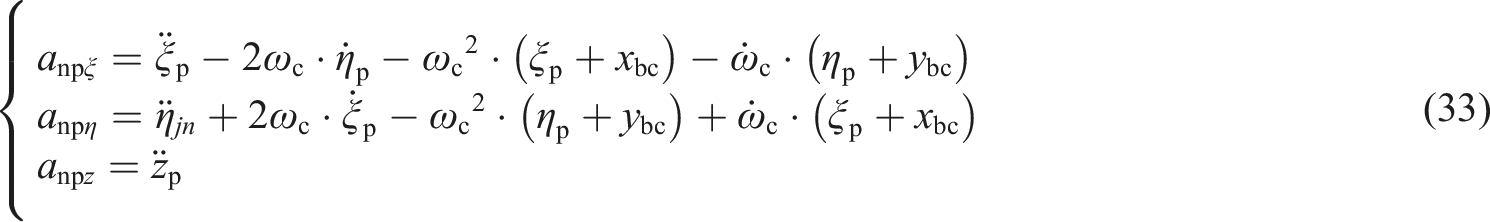
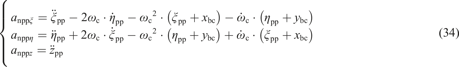
The absolute acceleration of the planetary gear node under INIS conditions is given according to equation (33), and the pin node is the same as the planetary gear node, as in equation (34).
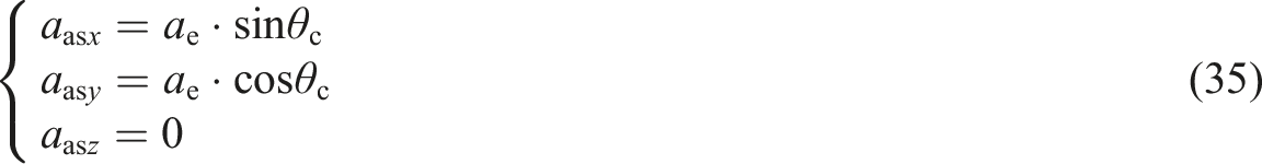
The additional term of absolute acceleration of the sun gear shaft during variable-speed horizontal flight is given according to equation (35), where θc = ωc · t.
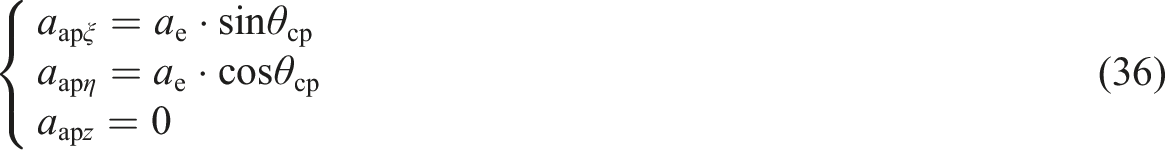
The additional items of the absolute acceleration of the gear ring and planet carrier shaft nodes are the same as those of the sun gear shaft node. Similarly, the additional terms of the absolute acceleration of the planetary gear and pin shaft node are the same. For the planetary gear node, as in equation (36), where θcp = φm1 + θc.
Because the body does not rotate relative to the ground coordinate system, the components of gravity on each coordinate axis do not change. In addition, according to equations 35, and 36, the axial distribution of the sun gear shaft, planet carrier shaft, and pin shaft nodes will not add an additional load.
According to equation (29), the non-inertial coefficients of the bending stress of each gear and the non-inertial coefficients of the gear pair contact stress under the condition of airframe variable-speed flight are shown in Figure 6. KNI of gear stress during variable-speed plane flight. (a) External gearing (b) Internal gearing.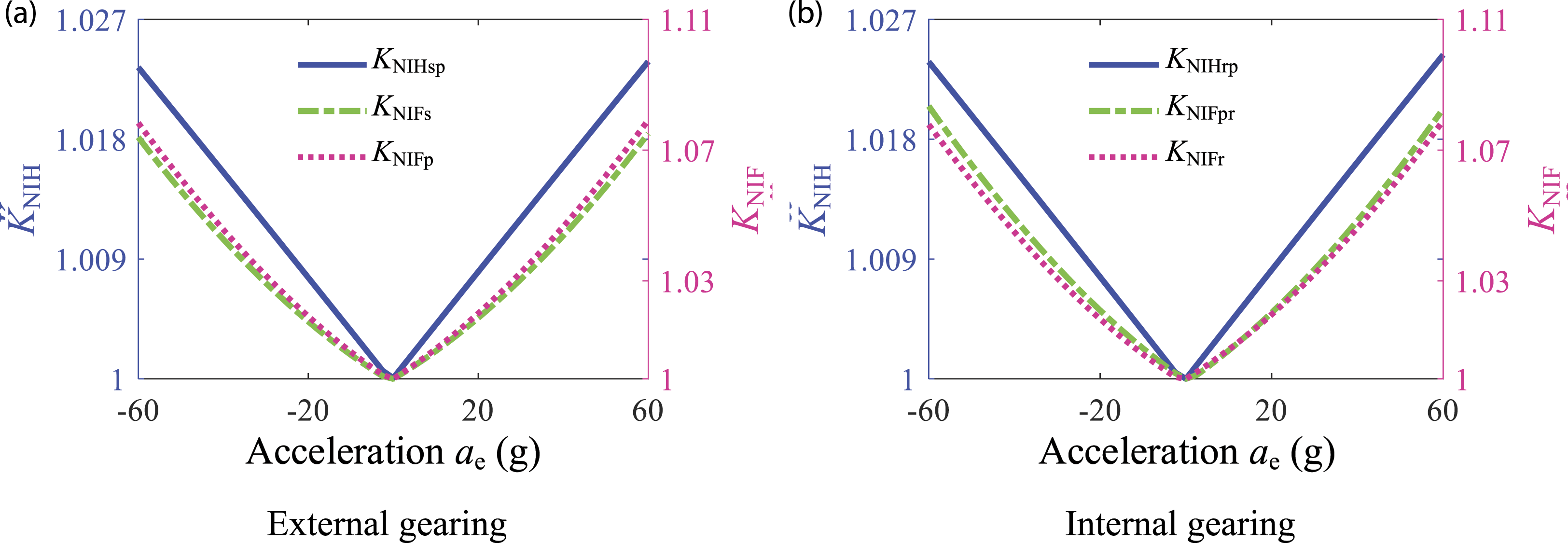
According to Figure 6, with an increase in |ae|, the non-inertial coefficient of the bending stress increases non-linearly, and the non-inertial coefficient of contact stress increases linearly.
Somersault movement
Compared with variable-speed horizontal flight, somersault motion covers maneuvers such as jumping, inverted flight, diving, and it is an important indicator for measuring the maneuverability of an aircraft. As shown in Figure 7, when the body turns somersaults, it turns and flies around the OX axis of the ground fixed coordinate system at the turning angular velocity, Ωd, and turning radius, R, and it completes a circular trajectory flight in a vertical plane. Schematic diagram of somersault movement.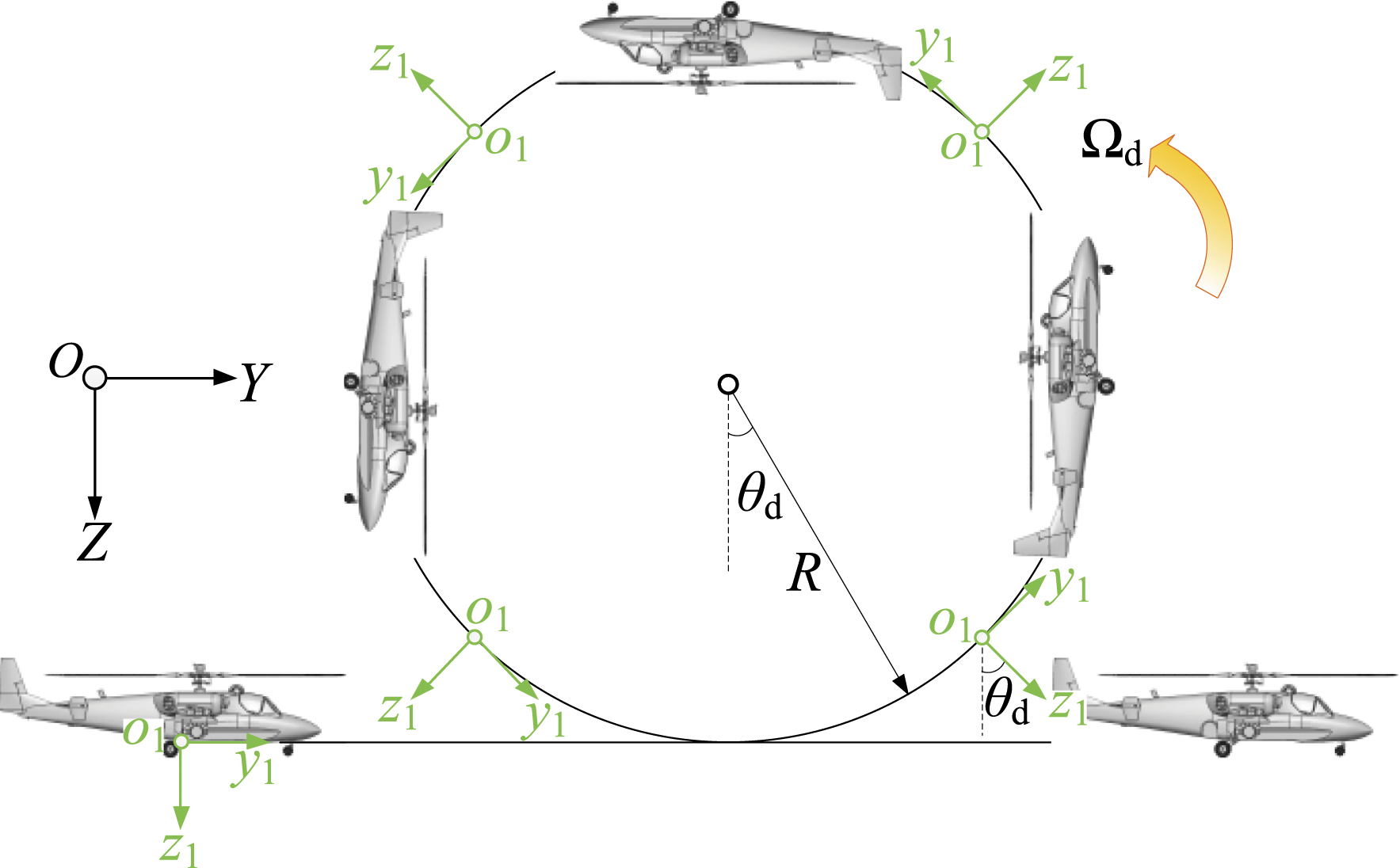
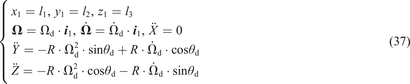
The relative motion parameters of somersault movement are given according to equation (37), where θd = Ωd · t.
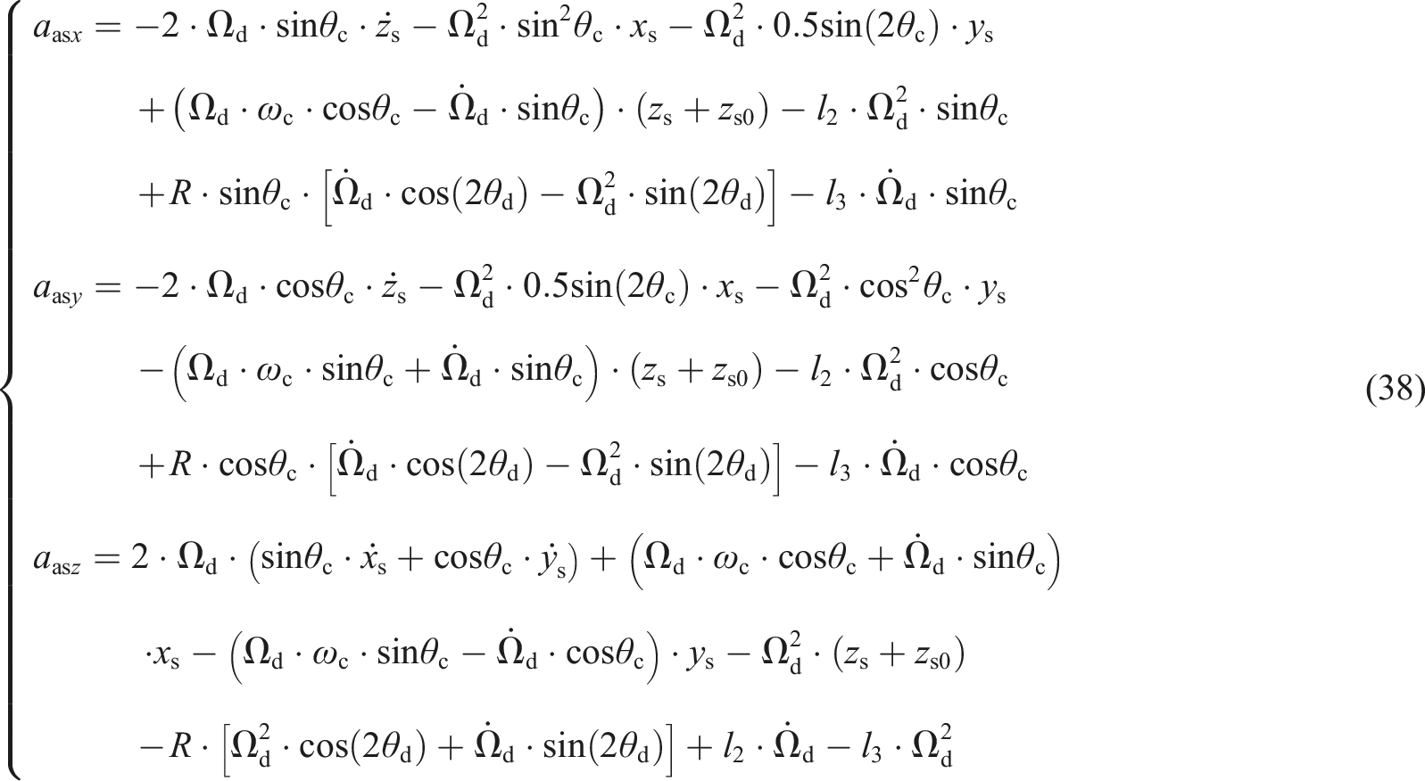
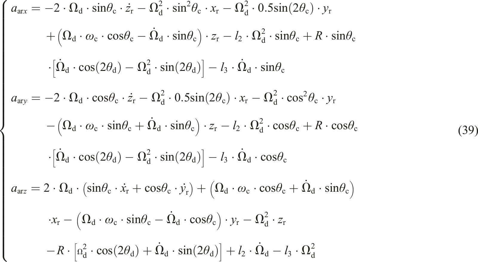
The additional term of the absolute acceleration of the sun gear shaft node is given according to equation (38), and the additional term of the acceleration of the planet carrier shaft node is the same. The ring gear node has no additional items owing to the axial distribution of the nodes, as shown in equation (39).
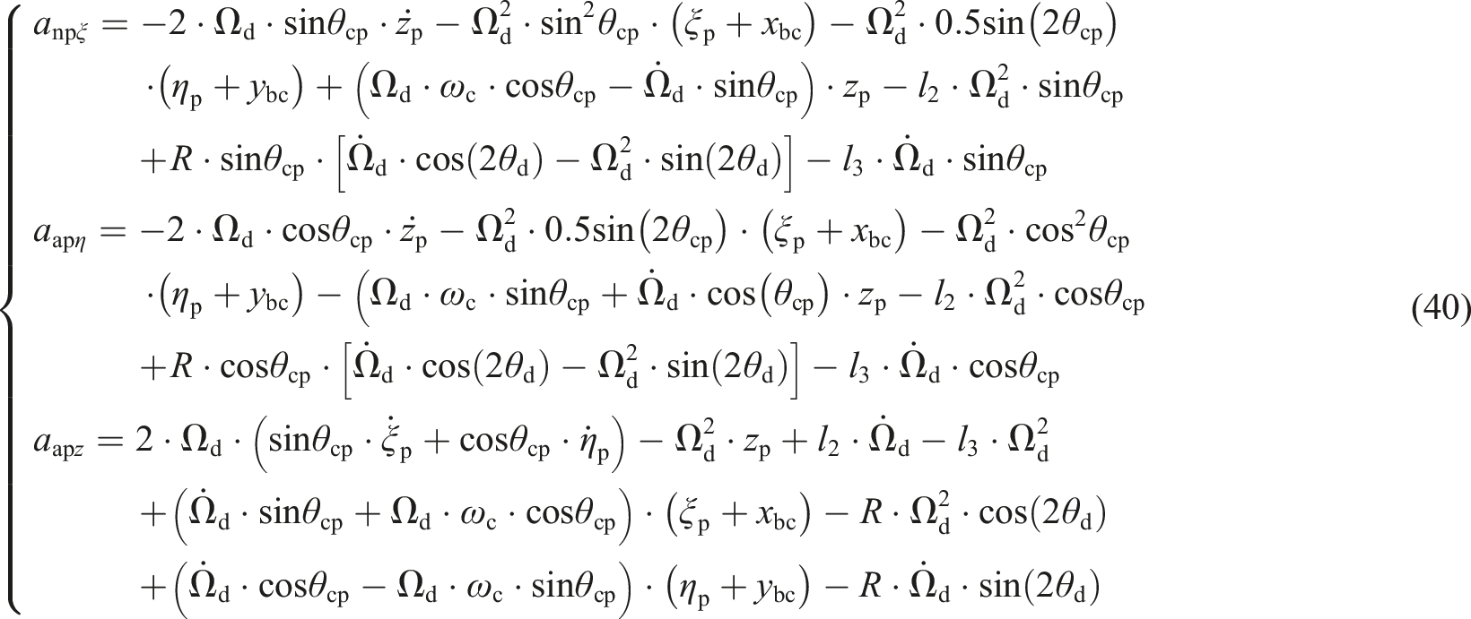
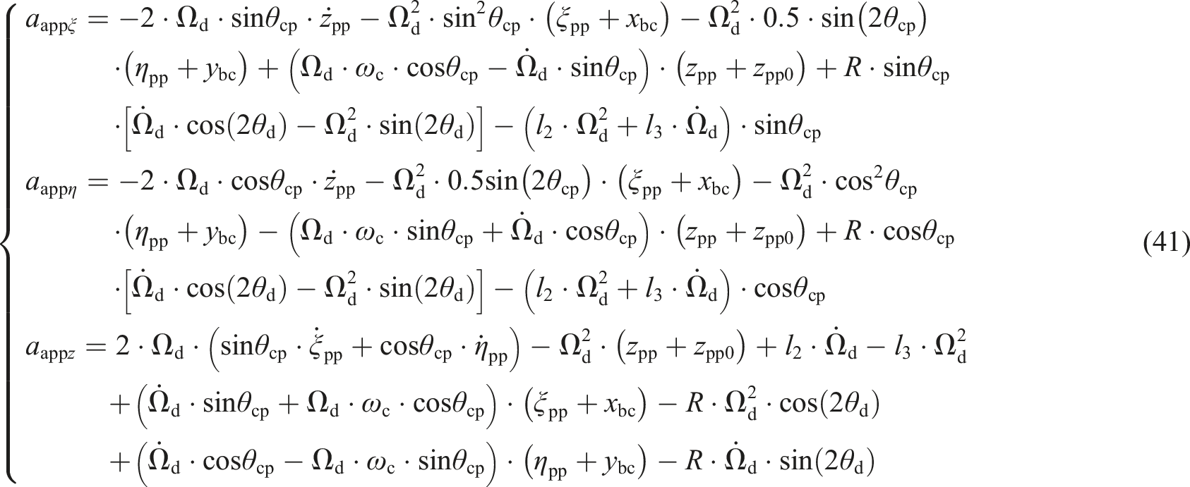
The additional items of the absolute acceleration of the planetary gear and pin shaft nodes are given according to equation (40) and equation (41), respectively.
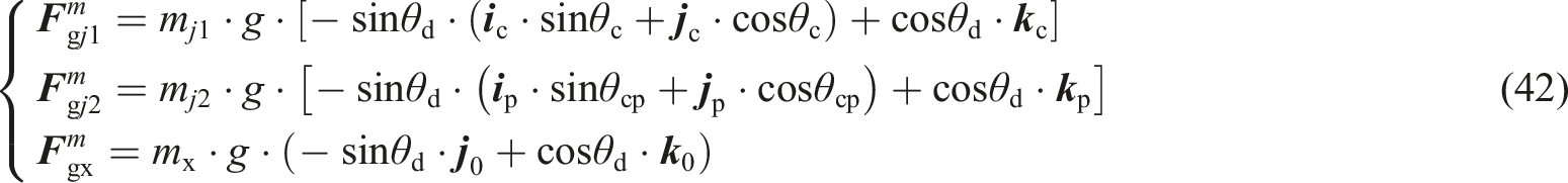
In addition, the gravity component of each member changes under the condition of the somersault motion, and the time-varying gravity component of each member is as follows:
The change law of the stress non-inertial coefficients of the planetary gear system when the body turns somersaults is shown in Figure 8. KNI of gear stress in somersault motion. (a) External gearing (Different turning radius) (b) Internal gearing (Different turning radius). (c) External gearing (Different angular velocity) (d) Internal gearing (Different angular velocity).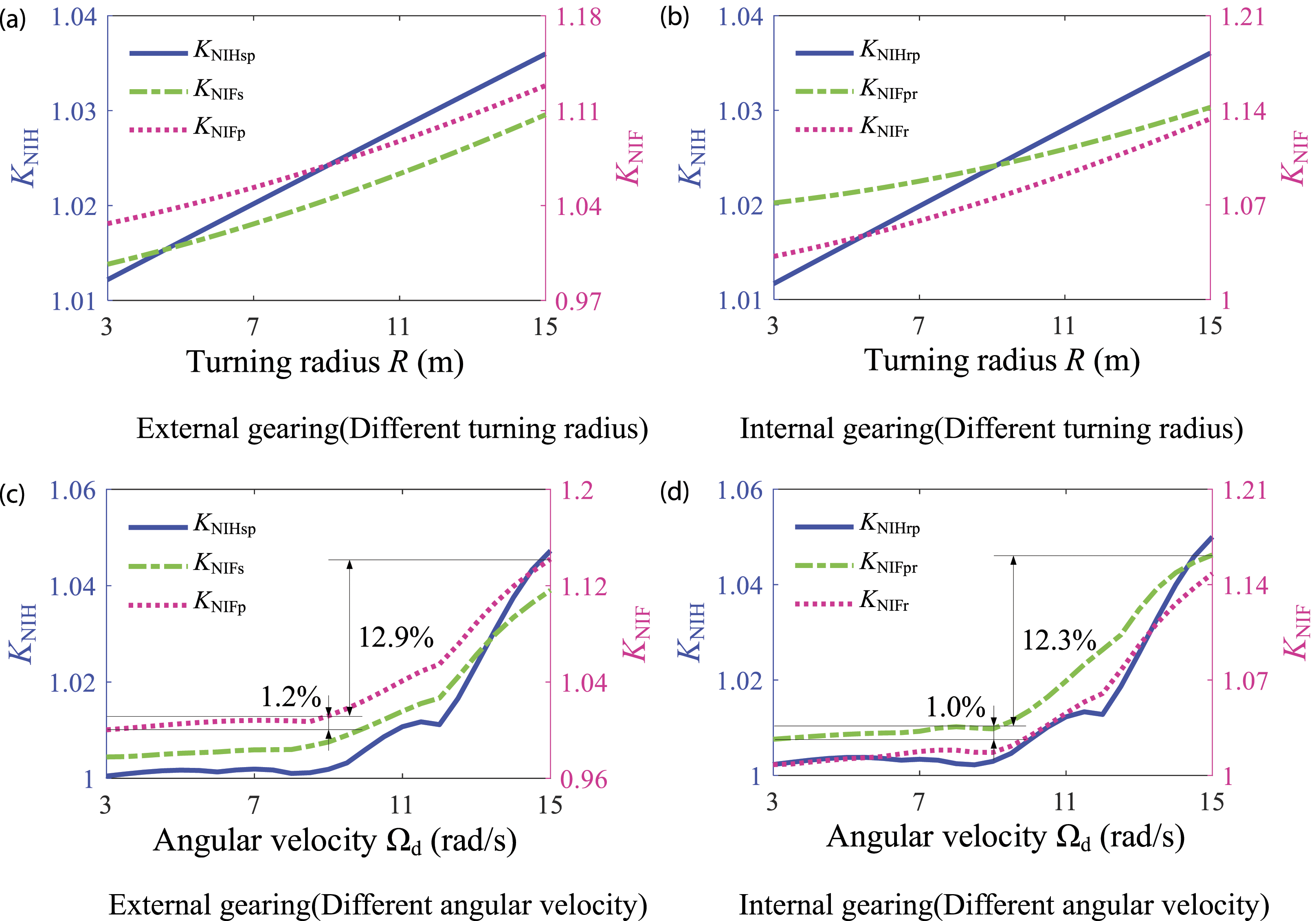
When the aircraft is in somersault motion, the external non-inertial effects on the transmission system will be greatly changed due to the changes of rotation angular velocity and turning radius. The inertial force brought by the non-inertial environment and gravity together affect the meshing state of the gear system, change its meshing force, and then change its contact stress and bending stress. Figure 8 shows that the change in the non-inertial system coefficient under the influence of the turning radius is relatively simple, and it increases linearly with the increase in R. The change in the non-inertial system coefficients under the influence of the turning angular velocity is more complicated, and KNIF and KNIH increase non-linearly with the increase in Ωd. The coefficient of the stress non-inertial system exhibits a small change in [3,9] rad/s and a large change in [9,15] rad/s. The KNIFp involved in external and internal gearing changes by 1.2% and 1.0% within [3,9] rad/s, respectively, and within [9,15] rad/s, they vary by 12.9% and 12.3%, respectively.
Effect of installation and manufacturing errors on the coefficient of non-inertial system of stress
Here, we consider the planetary gear tooth root bending stress non-inertial coefficient (KNIFp) and internal meshing contact stress non-inertial coefficient (KNIHrp) for discussion.
Installation and manufacturing errors
Installation error
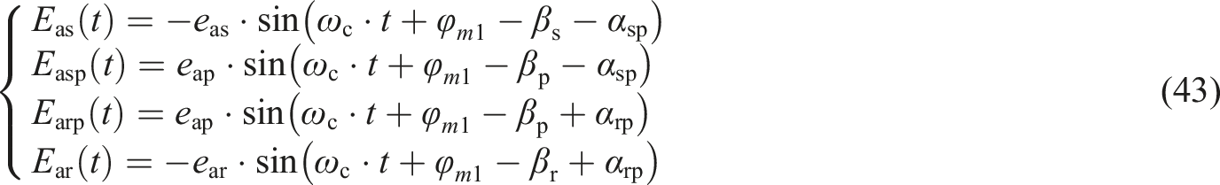
Installation error is the deviation between the theoretical rotation axis and the actual installation rotation axis of the gear produced during the assembly of the gear. According to the relationship between the installation error and the meshing line in Figure 9, the projection displacement of each gear installation error on the meshing line is given according to equation (43), where eas, eap, and ear represent the installation error values of the sun, planetary, and ring gears, respectively, and βs, βp, and βr represent the initial phase angle of the installation error of the sun, planet, and ring gears, respectively. Projection diagram of gear installation error to meshing line. (a) Installation error of sun gear (b) Installation error of planet gear (c) Installation error of ring gear.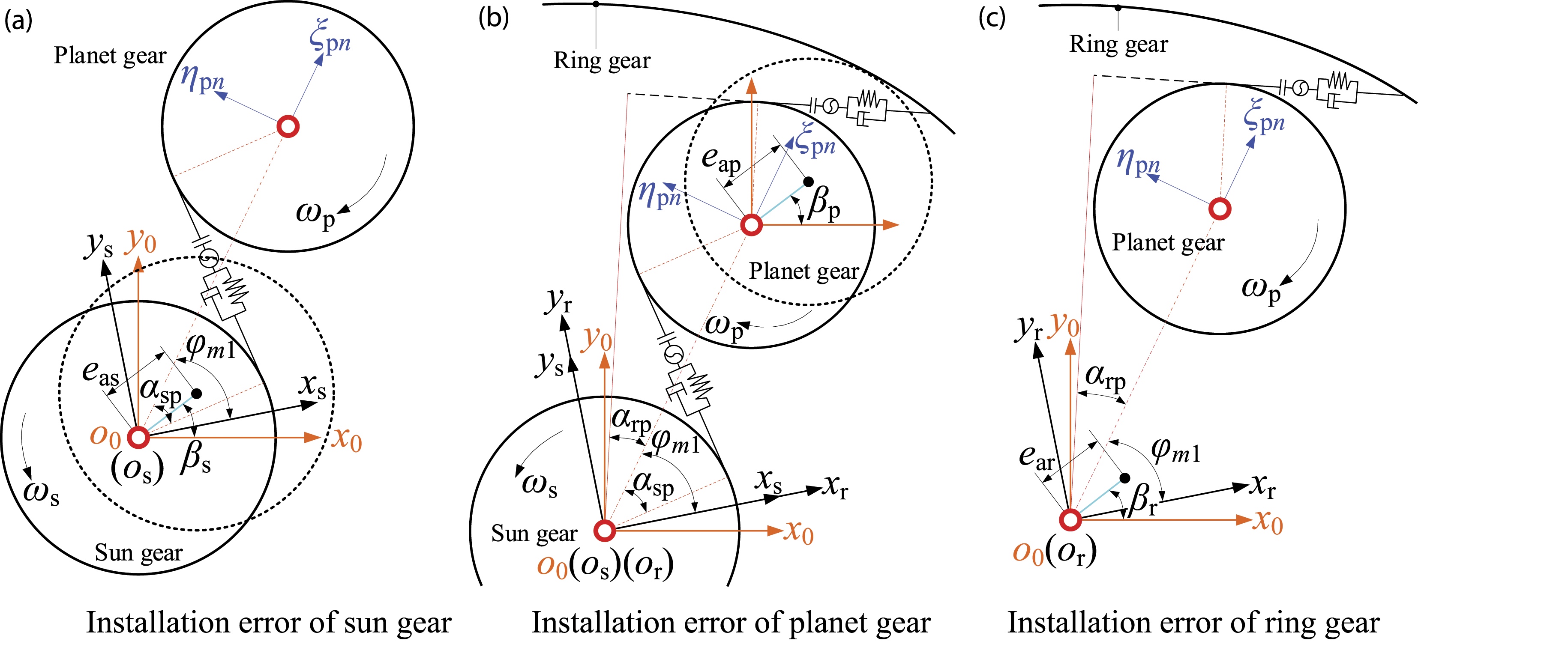
Manufacturing error
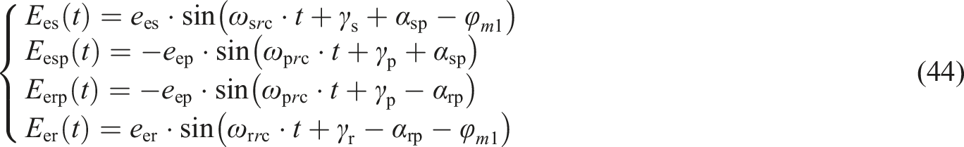
Manufacturing error is the deviation of the geometric center of the component from the actual center of rotation produced during the processing of the gear. Similar to the projection derivation process of the installation error on the meshing line, the manufacturing errors of the sun, planetary, and ring gears are projected on the meshing line, according to equation (44).
When only the INIS conditions are considered, the component manufacturing eccentricity error will cause an unbalanced force


Effect of errors on the KNI under the variable-speed horizontal flight
Installation error
The variation trend of the stress non-inertial coefficient of the airframe with the gear installation error during horizontal flight with variable speed is shown in Figure 10. Effect of gear installation error on KNI of gear stress during variable-speed plane flight.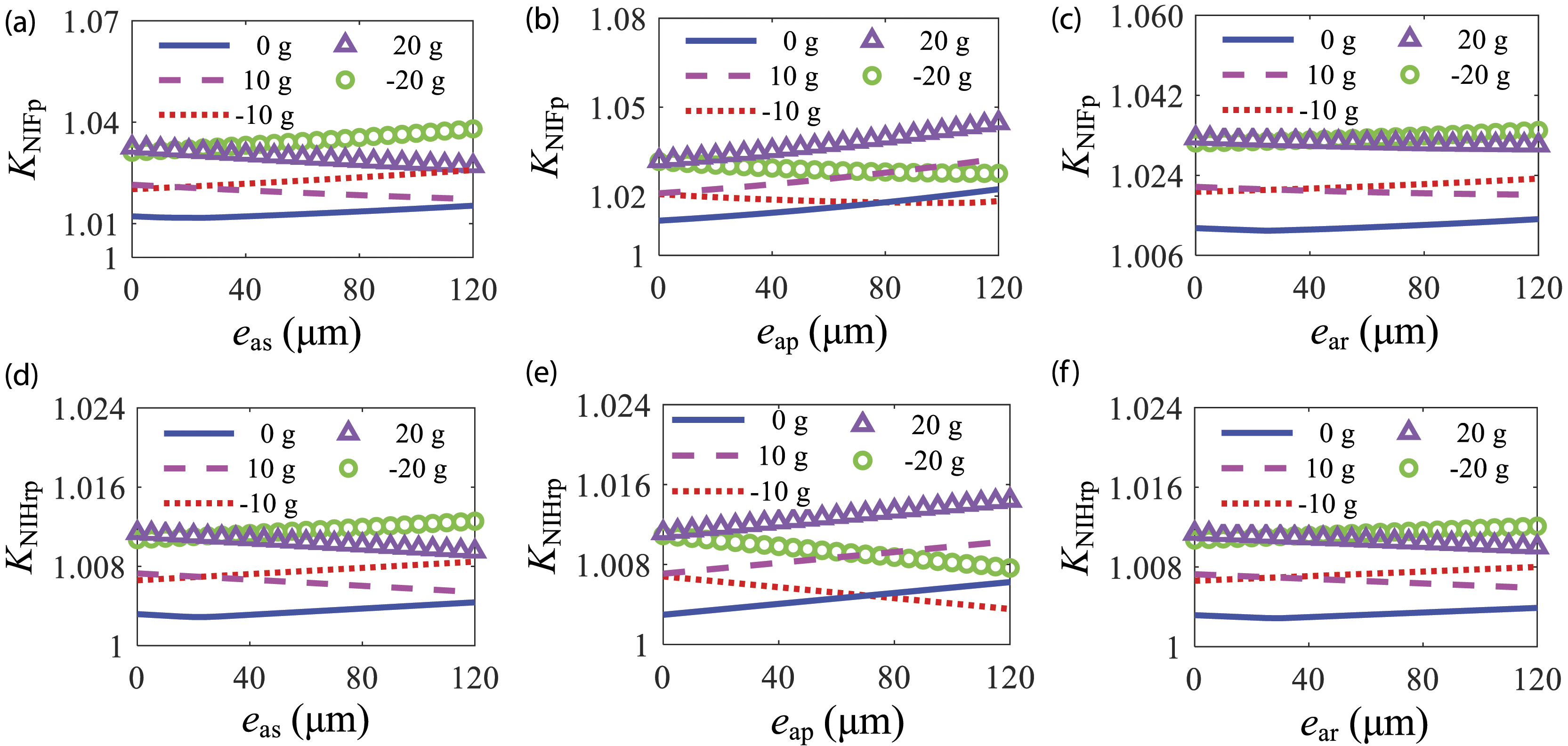
Installation error refers to the deviation between the theoretical rotation axis and the actual installation rotation axis generated during the assembly of the gear component. The deviation direction of the installation rotation axis from the theoretical rotation axis does not rotate with the gear rotation, which will cause displacement excitation. When ae = 0 g, the stress non-inertial coefficients KNIFp and KNIHrp first decrease and then increase with an increase in the installation error of the sun (eas) and ring (ear) gears, and they increased with an increase in the installation error of the planet gear (eap). When the horizontal flight is accelerated, KNIFp and KNIHrp decrease linearly with the increase in eas and ear, and they increase with the increase in eap. The changing trend during deceleration and horizontal flight is opposite to that during acceleration and horizontal flight.
Manufacturing error
Manufacturing error refers to the deviation between the geometric center of the component, the center of mass and the actual center of rotation generated during gear processing. The deviation direction of the actual center of rotation and the center of mass from the theoretical geometric center of the component rotates with gear rotation. The deviation between the geometric center of the component and the actual center of rotation will generate displacement excitation, and the deviation between the center of mass and the actual center of rotation will generate centrifugal force, resulting in unbalanced excitation.
When the airframe is flying at a variable speed, KNIFp and KNIHrp change slowly with the manufacturing error of the sun (ees) and planetary (eep) gears, as shown in Figure 11. KNIFp increases non-linearly with an increase in ees and eep. KNIHrp decreases as ees and eep increase when ae ≥ 0 g, and it increases as ees and eep increase when ae < 0 g. The variation of KNIFp and KNIFp with gear ring manufacturing error (eer) varies with ae: they decrease first and then increase with the increase in eer during uniform flight, non-linearity decreases with the increase in eer during acceleration flight, and non-linearity increases with the increase in eer during deceleration flight, as shown in Figure 11(c) and Figure 11(f). Effect of gear manufacturing error on KNI of gear stress during varied-speed plane flight.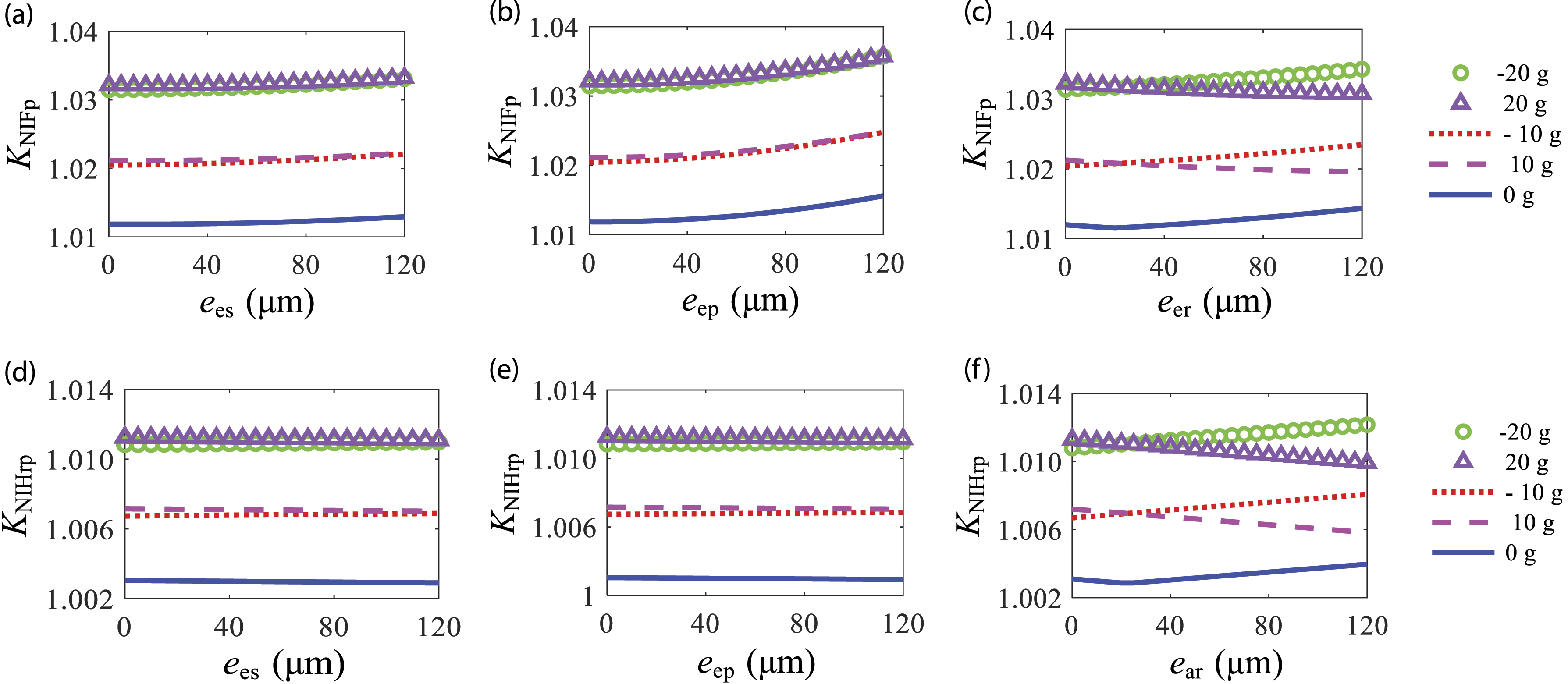
Effect of errors on the KNI under somersault motion
Installation error
When the body somersaults, the turning angular velocity of the body changes the trend of KNI of gear stress with gear installation errors, as shown in Figure 12. Similar to the previous article, a larger turning angle speed corresponds to a larger non-inertial coefficient. However, when the gear installation error is too large, this rule may be changed. The main reason is that the additional excitation brought by the installation error can offset some non-inertial system effects, but this change is relatively small. Compared with the error, the turning angle speed has a greater impact on the non-inertial system coefficients. Effect of gear installation error on KNI of gear stress under somersault motion.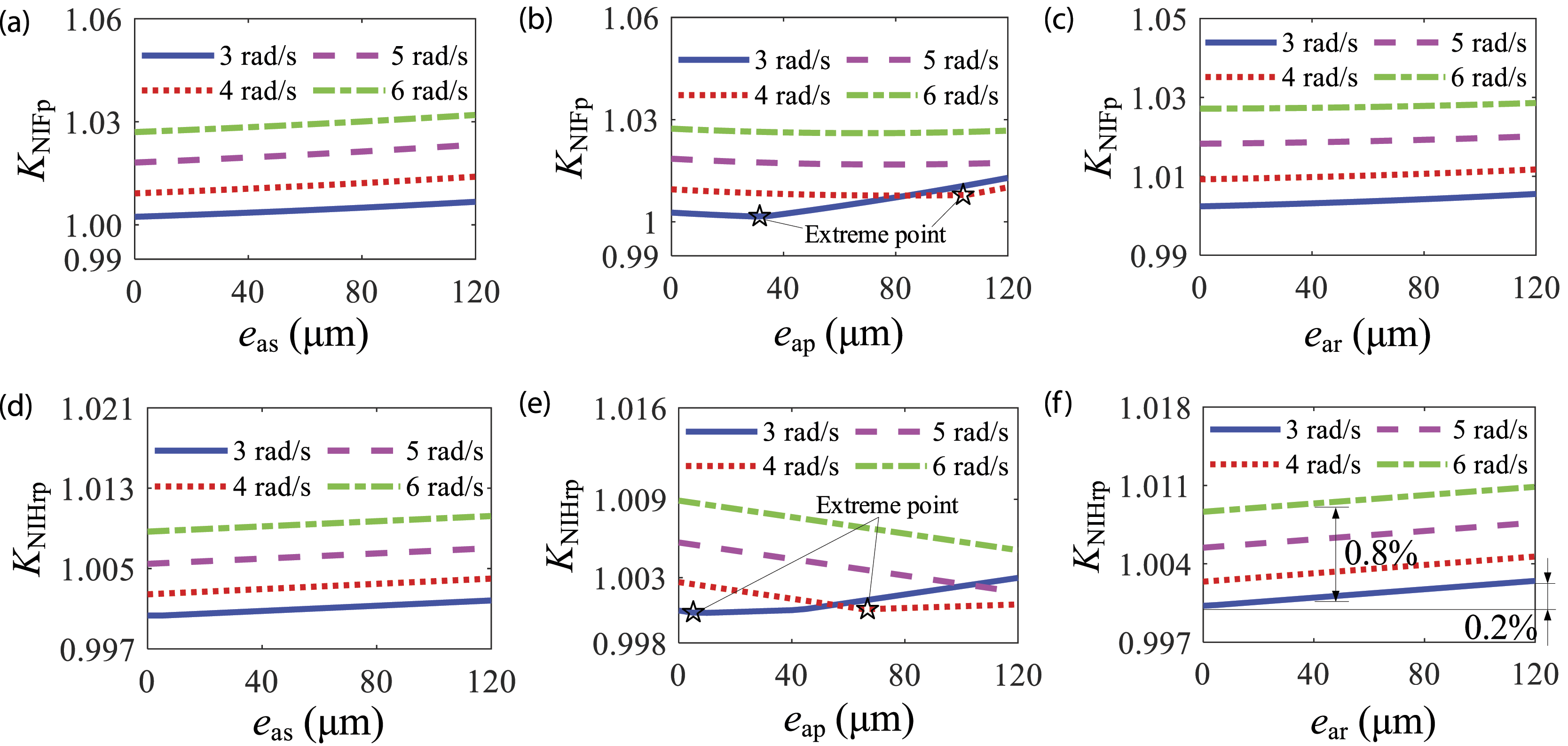
When the body turns somersaults at an angular velocity of [3,6] rad/s, KNIFp and KNIHrp increase linearly with an increase in the installation error of the sun (eas) and ring (ear) gears. When Ωd ∈ [3,4] rad/s, KNIFp and KNIHrp first decrease and then increase with an increase in the installation error of the planetary gear (eap), and the extreme points of the curve move to the right with the increase in Ωd. When Ωd increases to 5 rad/s, KNIFp and KNIHrp decrease with an increase in eap.
Manufacturing error
The unbalanced force generated by the gear manufacturing error will affect the meshing state of the transmission system, but the influence on different parts of the transmission system is not completely the same, especially the gear ring manufacturing error, which is contrary to other laws. The reason is that the centrifugal force caused by the manufacturing error of the gear ring is not in the same direction as the external inertial force. Figure 13 shows the variation trend of KNIFp and KNIHrp with gear manufacturing errors under different flipping angular velocity conditions. According to Figure 13(a) and Figure 13(d), the values of KNIFp and KNIHrp corresponding to different Ωd are quite different, but the change is slower with the increase in the manufacturing error of the sun gear (ees), and the changing trend is similar. The trend of KNIFp and KNIHrp with eep does not change under the influence of the flip angular velocity: non-linearly increases with the increase in eep, as shown in Figure 13(b) and Figure 13(e). KNIFp increases with eer, and KNIHrp decreases with eer, as shown in Figure 13(c) and Figure 13(f). Effect of gear manufacturing error on KNI of gear stress under somersault motion.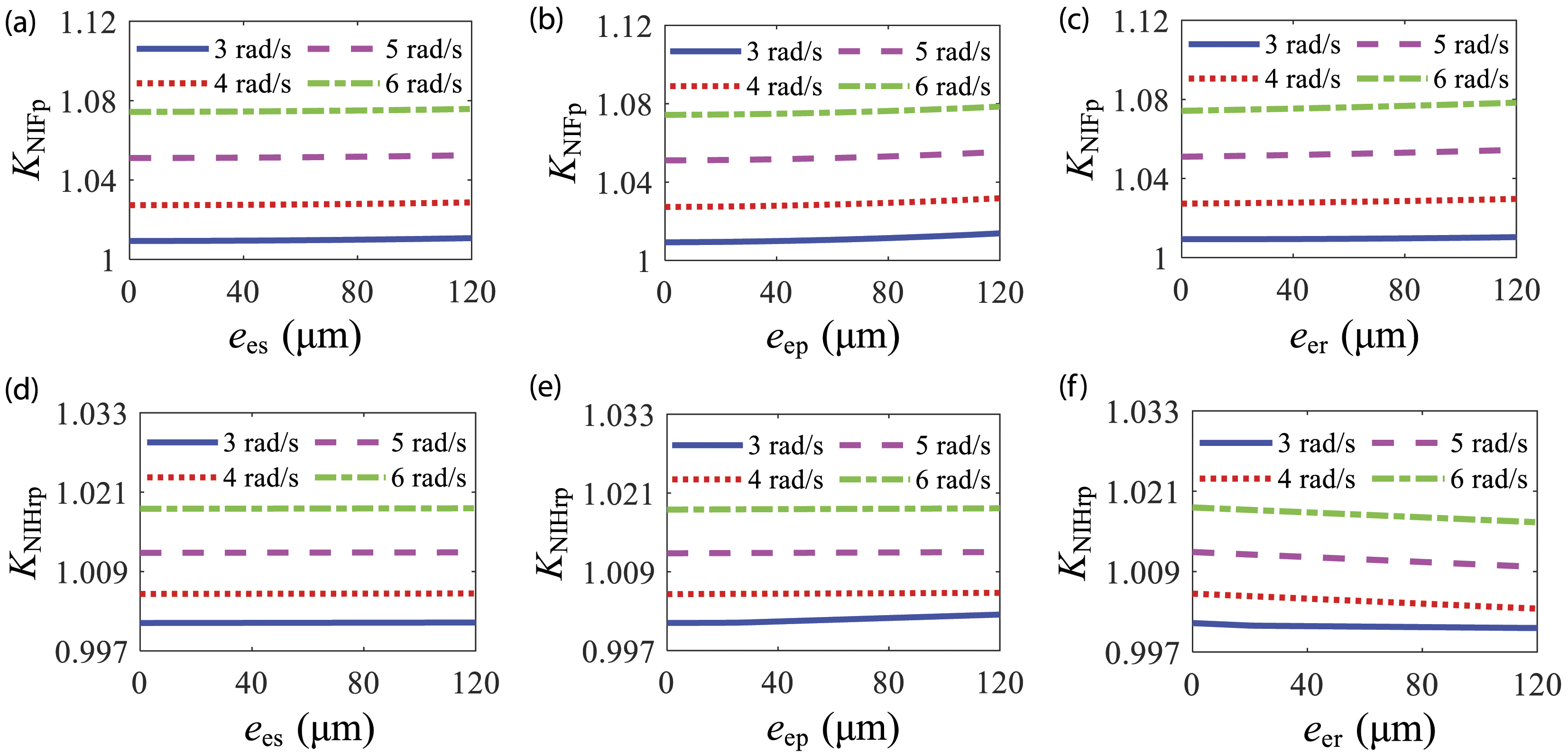
It can be observed from Figures 10–13 that the increase in gear error will affect the stress non-inertial coefficient, but the NIS effect produced by maneuvering flight is significantly more affected. As shown in Figure 12(f), when the body is in somersault motion and the ring gear manufacturing error increases from 0 to 120 μm, KNIHrp increases by 0.2%. When the error is constant and the turning angular velocity increased from 3 rad/s to 6 rad/s, KNIHrp increased by 0.8%. According to Figure 8, when the turning angular velocity increases, the stress non-inertial coefficient changes significantly.
Conclusion
This work considered the complex combination of INIS and ENIS, and studied the effect of high maneuvering conditions on the dynamic stress of PGT. The specific conclusions are as follows: (1) The dynamic and dynamic stress calculation models of the PGT under NIS are established, and the dynamic stress of each gear tooth root bending and the contact dynamic stress of each gear pair under NIS conditions were obtained. (2) The stress non-inertial coefficients are defined, and the influence of the airframe’s variable-speed horizontal flight and somersault motion state on the stress non-inertial coefficients is discussed. The results indicate that the stress non-inertial coefficients increase with an increase in the mobility of the body. The NIS effect has a significant influence on the stress non-inertial system coefficient. (3) The influence of gear installation and manufacturing errors on the coefficient of the stress NIS under two maneuvering flight states was studied. The maneuvering flight status changes the trend of the stress non-inertial coefficients with gear installation and manufacturing errors. In addition, compared with the gear installation and manufacturing errors, the NIS effect has a greater impact on the stress non-inertial coefficient.
Footnotes
Acknowledgments
This study is part of research project supported by the National Natural Science Foundation of China (grant number 52105051), the Innovation Group Science Foundation of Chongqing Natural Science Foundation (No.cstc2019jcyj-cxttX0003) and the Project funded by China Postdoctoral Science Foundation (grant number 2021M700585). The authors would like to express their gratitude for the support of the funding authority.
Author contributions
Conceptualization: J.W. and A.Q.Z.; Methodology: A.Q.Z. and J.W.; Software: H.C.; Validation: A.Q.Z. and M.F.C.; Formal analysis: A.Q.Z. and M.F.C.; Investigation: H.C. and B.P.; Resources: M.F.C.; Data curation: B.P.; Writing—original draft preparation: M.F.C.; Writing—review and editing: M.F.C., J.W. and A.Q.Z.; Visualization: H.C. and B.P.; Supervision: J.W. All authors have read and agreed to the published version of the manuscript.
Declaration of conflicting interests
The author(s) declared no potential conflicts of interest with respect to the research, authorship, and/or publication of this article.
Funding
The author(s) disclosed receipt of the following financial support for the research, authorship, and/or publication of this article: This work was supported by the Innovation Group Science Foundation of Chongqing Natural Science Foundation (cstc2019jcyj-cxttX0003), National Natural Science Foundation of China (52105051) and China Postdoctoral Science Foundation (2021M700585).
Availability of data and materials
The datasets generated during and/or analyzed during the current study are available from the corresponding author on reasonable request.