
Abstract
The high-power electromechanical transmission (EMT) system is a typical dual-mode hybrid power transmission system. The torque fluctuation of internal combustion engine causes serious shock and vibration problems of EMT. Suppressing torsional vibration based on high dynamic motor torque regulation is an important way to improve the working life and stability of EMT system. First, a lbased on the lumped parameter linear dynamic model,the torsional vibration characteristics are analyzed. Second, a fluctuating speed estimation method is proposed based on the uniformly accelerated motion model and linear regression, and a digital high pass filter is designed. Then, a master-slave coupling active torsional vibration control strategy is proposed, and a PD control algorithm based on speed feedback is designed. The variation rules of control parameters is analyzed. Finally, the control effect is verified by experiments. The results show that the lever coefficient K ab and differential coefficient K d of master-slave control can change the natural frequency of torsional vibration of the system, thus significantly changing the vibration response of the system. Selecting appropriate control parameters can achieve peak clipping of EMT torsional resonance.
Keywords
Introduction
Hybrid electric vehicle (HEV) realizes the driving performance of fuel efficiency by combining traditional internal combustion engine (ICE) engine with electric motor. This technology has been developed by motor companies with different types of transmission system structure to meet the future market demand and environmental challenges.1,2 The power system structure of hybrid electric vehicle is complex, and there are different vibration problems compared with traditional vehicles. The torsional vibration of the engine crankshaft transmitted through the transmission system will cause the structural vibration of the vehicle body and NVH problems in a wide frequency range.3,4 The power system of hybrid electric vehicle can be classified according to the power flow direction. In the series hybrid type, the engine is connected with the generator to convert the power of the engine into electric energy, so there is no direct connection between the engine and the transmission system of the vehicle. In the parallel hybrid type, both the engine and the motor can be connected to the transmission system.5–8 When running in parallel, the engine and the transmission system are mechanically connected. In the power split type, once the mixed mode operation is adopted, the engine is always directly mechanically connected with the transmission system. Therefore, the direct connection between engine and transmission may cause NVH problems related to traditional internal combustion engine vehicles. 9 Among them, the most important is the rotational vibration excited by the torque fluctuation of the internal combustion engine crankshaft. This torsional vibration is transmitted from the rear end of the crankshaft to various components on the transmission chain.
This torsional vibration is continuous. With the change of engine working conditions, the greatest harm occurs at the critical speed point of the engine, which will result in premature wear, failure, and excessive noise of transmission system parts. Therefore, design of torsional vibration reduction includes two aspects. One is to reduce the transmission of vibration from the crankshaft to the transmission, that is, vibration isolation of incessant vibration. The second helps decrease the amplitude of vibration when speed oscillations.
Reducing vibration transmission on the crankshaft is a quite traditional problem. The main method is to increase the inertia of the end of the crankshaft and decrease the corresponding angular acceleration with the help of the flywheel in front of the clutch. High-performance flywheels can increase filtering, improve damping, and reduce the transmission rate of vibration. For example, dual mass flywheels, 10 which connect two flywheels through an arc springs or cams and blades, are widely used at present. This coupling between flywheels is not restricted to two parts, and three mass flywheels are also under study. 11 In addition, connecting the flywheel through a device that transmits the dynamic effect unevenly also has a good vibration isolation effect, which leads to the appearance of a planetary gear flywheel. 12 A novel method is the creation of an “escape way” to capture the energy of the oscillations and reduce their amplitude. This leads to multiple tuned mass dampers 13 and centrifugal pendulum dampers. 14 The most advanced method goes to modify the mechanical properties of the flywheel, such as inertia or stiffness. Controllable magnetorheological fluid15,16 or elastomers17,18 is introduced into the category of the semi-active flywheel and active flywheel.
Another method to reduce vibration transmission of the crankshaft is damper and absorber. Lanchester damper has been introduced in the early stage of ice development, and viscoelastic or rubber-based elements are still referenced as dampers.19,20 Built-in 21 mechanical torsional vibration dampers has also been studied. In recent years, several semi-active or active devices have been studied, many of which use magnetorheological fluid or elastomer as a control medium.22–24
Although the vibration isolation measures can optimize the vibration response of the system and cannot eliminate the vibration, the crankshaft vibration will still be transmitted to the gears of the gearbox, so it is the source of torsional vibration in the rest of the transmission system. 25
The influence of engine damping elements of the transmission system is tantamount to decrease the critical speed, generally lower than idle speed. However, the residual vibration will still excite extra low-order modes of EMT torsion. Fortunately, the amplitude is weak and the harm is limited.
For electromechanical composite drive systems, active motor provides the possibility for torsional vibration suppression of the drive system. Numerous studies have considered the active vibration control algorithm of parallel hybrid electric vehicles. Cauet et al. 26 designed a linear variable parameter control strategy based on the internal model principle of multi sinusoidal continuous disturbance, which reduced the first and second-order speed oscillation of engine torque ripple. Morandin et al. 27 connected the motor to the engine as the control actuator, and proposed a control algorithm based on adaptive multi resonance controller. However, the complex structure of the split transmission makes the dynamic analysis of the powertrain system difficult.28,29
There are more power sources and more complex power action and vibration transmission path in power split hybrid electric vehicle, which makes the realization of active vibration control extremely difficult. According to the principle of nonlinear observer and model-based torque estimator, Zeng et al. 30 designed a dynamic coordination strategy based on predictive model to realize the smooth switching from EVT mode to EV mode, but the control strategy is not suitable for continuous vibration process. Zhang et al. 31 designed a feedforward compensation control algorithm based on harmonic injection of motor current, which uses the torque effect of harmonic current to offset the torque ripple of engine. However, it is difficult to accurately identify the real-time torque ripple of power split hybrid vehicle.
You et al. 32 proposed a sliding mode control scheme to actively suppress the vibration of the power system. However, the torque relationship between motor and engine is established by assuming steady-state conditions. Ito et al. 33 designed a feedforward filter based on transfer function to compensate the torque ripple of the engine by compensating the torque of the motor. However, it is difficult to identify the transfer function of hybrid electric vehicle with power split. In addition, it is difficult to obtain the pulsating torque from the engine. Chen et al. 34 considered the inertia effect of engine active damping vibration when starting and stopping, but ignored the inertia effect of planetary gear. Wang et al. 35 proposed a mode conversion coordinated control algorithm for power split hybrid electric vehicle, which adopts model reference control to actively damp the vibration caused by acceleration without considering the torque fluctuation of engine. However, the algorithm does not consider the moment of inertia of planetary gear and does not work for low-order torsional resonance.
Active damping method based on self-learning algorithm is a common method in active vibration control, which has good adaptive ability and is insensitive to the changes of model parameters. The application scenario of active damping method is that the damping force from the actuator acts on two degrees of freedom with the same motion relationship. However, in EMT system, two motors do not have the same motion relationship. Therefore, the active damping method cannot be simply used to suppress the torsional vibration of EMT system. Madonski et al. 36 proposed a new efficient mode switching control method and an adaptive double loop control framework for mode switching control. FXLMS algorithm is the most famous algorithm in the active control of forced vibration 37 because it is reliable and easy to implement. FXLMS algorithm is widely used in active noise control, 38 and Zhang et al. 39 take advantage of the motor of hybrid electric vehicle to actively suppress engine vibration.
This paper focuses on the active suppression of low-frequency torsional vibration of EMT system, the master-slave motor control method is first proposed, the concept of leverage ratio is proposed, and the influence of leverage ratio on the resonance point of the system is analyzed. The active control algorithm of EMT torsional vibration based on PD algorithm is designed. The simulation results show that the control algorithm has significant suppression effect on two low-order torsional resonance amplitudes of the system.
Torsional vibration characteristics of electromechanical transmission system
Static characteristic of electromechanical transmission
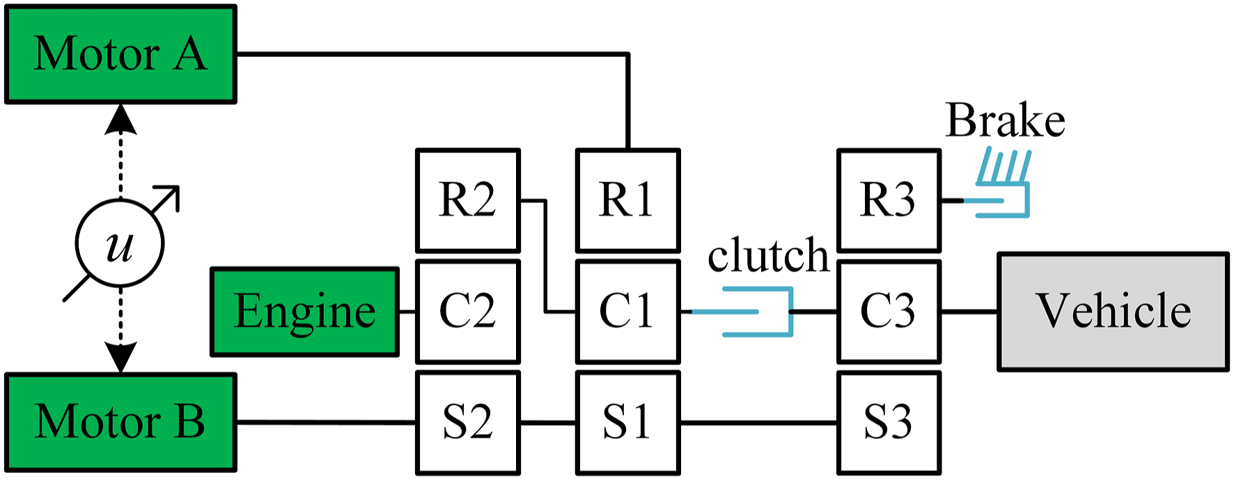
Figure 1(a) shows the structure diagram of a typical dual-mode power split hybrid electric vehicle. The core structure of the vehicle is the electromechanical transmission (EMT) which realizes the power split function. The external part of the transmission is connected with the internal combustion engine, axle and electric drive components. Three planetary gear sets (PG1, PG2, and PG3), two motors (MGa and MGb), a clutch, and a brake are integrated in the transmission box, in which (i = 1, 2, 3) is the grade of PG. The engine is meshed with planet carrier gear of PG1, and MGa is connected with ring gear of PG2 and inverter of battery. The sun gear and ring gear of PG1 are, respectively, connected to the bracket of the sun gear and PG2. The MGB is connected to the sun gear of the PG3. The output shaft is connected to the bracket of the PG3. By engaging or disengaging the brake and clutch in the transmission, two different hybrid drive modes can be switched.
1
In the first working mode (EVT1 mode), the brake is engaged and the clutch is disengaged. In this mode, the output driving torque is relatively large, but the output speed is low, which can only cover the low speed range of the vehicle. When the vehicle accelerates to a higher speed, the clutch engagement and brake disengagement are switched to the second working mode (EVT1 mode) by operating the oil pressure valve. Compared with EVT 1 mode, in EVT2 mode, the vehicle can run at a higher speed. The maximum driving torque of EMT decreases with the increase of vehicle speed, and the maximum torque is limited by engine power. In the whole speed range, the transmission ratio from engine to wheel changes continuously according to the speed. The engine and vehicle motion are decoupled. By controlling the transmission ratio through the coordinated control of engine and motor,
6
the engine can always run in the working range with the highest fuel efficiency.7,8 Structure of HEV equipped with EMT. (a) Structure of dual mode power split HEV, (b) Multi-DOF lumped parameter dynamic system model.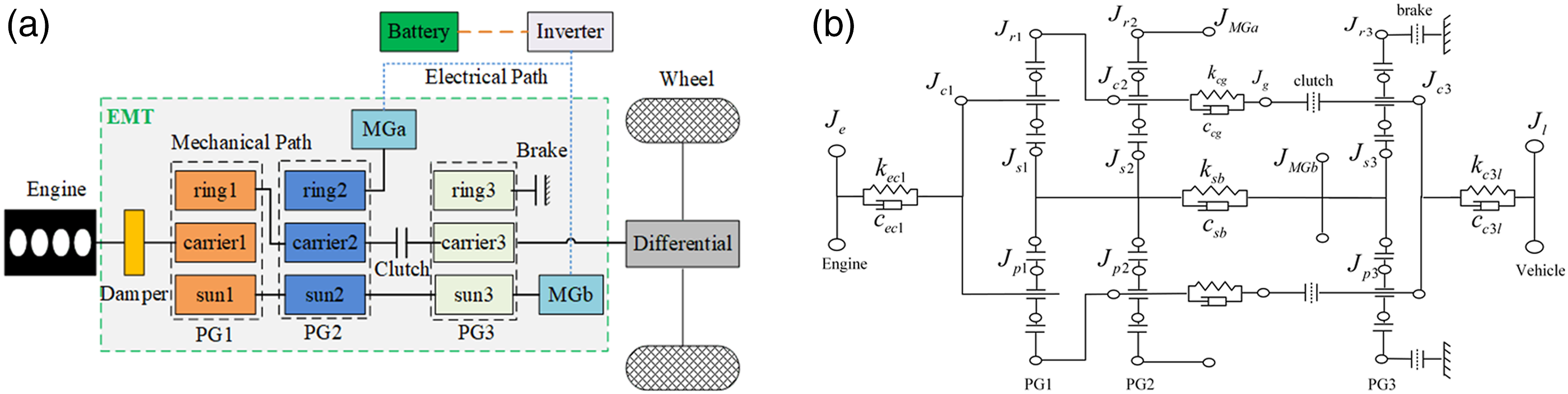
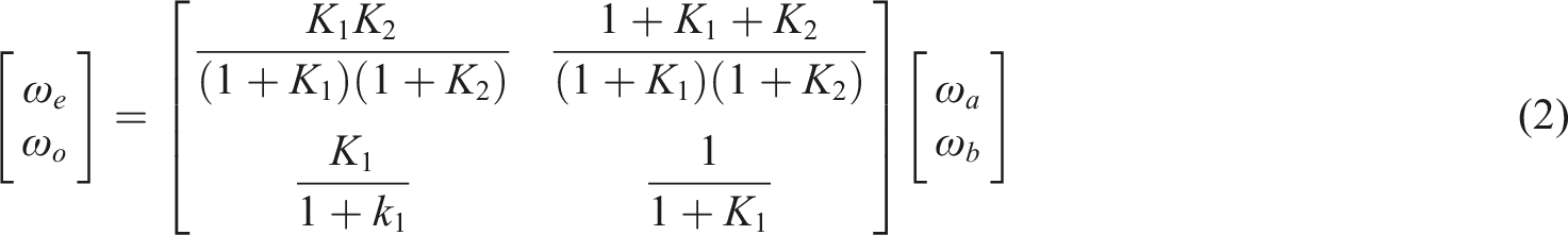
Assuming the shaft is the rigid, according to the speed and torque constraints of planetary mechanism, the speed constraint relationship between engine, mga, MGB, and transmission output shaft can be obtained under different EVT modes.
EVT1 mode
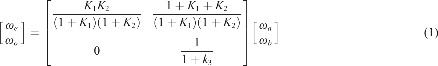
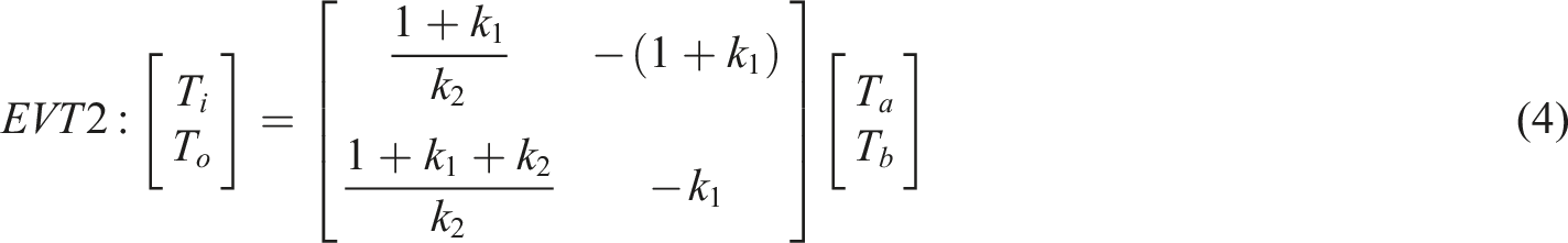
EVT2 mode
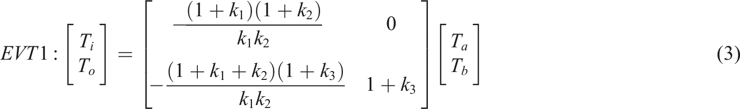
The torque between the engine, MGA, and MGB also follows a certain relationship under steady-state conditions by ignoring the frictional force between each planet gear, as follows:
EVT1 mode
EVT2 mode
Dynamic model of electromechanical transmission
This paper studies the low-frequency torsional vibration and its control, which is harmful to the system. The meshing of shaft and gear with high torsional stiffness is ignored. At the same time, it is assumed that the gear is a rigid body, clutch and brake do not have sliding friction. According to the bench test analysis of a heavy dual-mode power split hybrid electric vehicle, the concentrated parameter angular vibration model of the hybrid electric vehicle is established, as shown in Figure 1(b). The model abstracts 4 spring damping elements and 16 inertia disks with concentrated mass.
Figure 1(b) shows the dynamic HEV model, where the subscript e is the engine and l is the load of the vehicle, while MGa or MGb can act as motor or generator respectively according to the current EVT mode. s represents the sun gear, c represents planet carrier, r represents ring gear, p represents planetary gears.
Since J
r1
-J
c2
, J
s1
-J
s2
, J
r2
-J
mga
, and J
s3
-J
mgb
are rigid body components, they have the following motion constraints
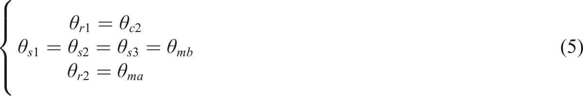
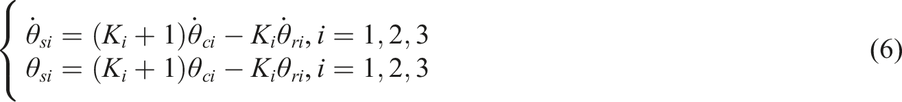
According to the motion relationship of rigid planetary gear train, there are the following motion constraints
When the system is running, only one of the clutch and brake is closed, with the following motion constraints
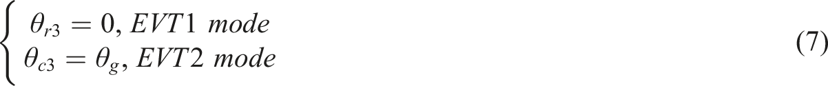
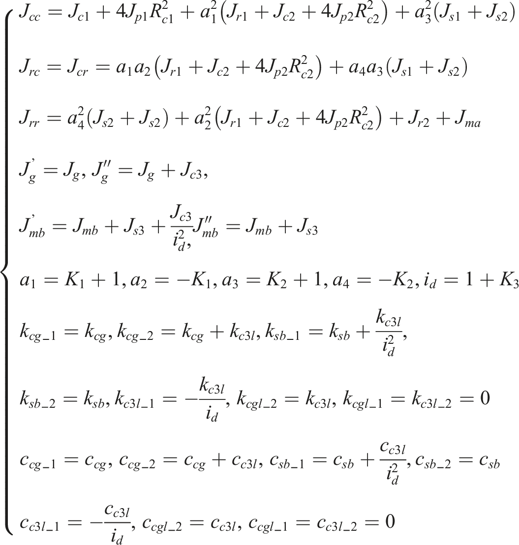
By combining equation (5), (6) and equations (7), and (10) associated degrees of freedom can be eliminated, and the number of independent degrees of freedom of the system becomes equation (6), which is obtained by taking the independent degrees of freedom of the system as the generalized coordinate
Taking the driving force and load force of the system as the external force, the generalized external force of the system can be obtained as
According to Lagrange’s equation, the system equation in matrix form can be obtained as follows

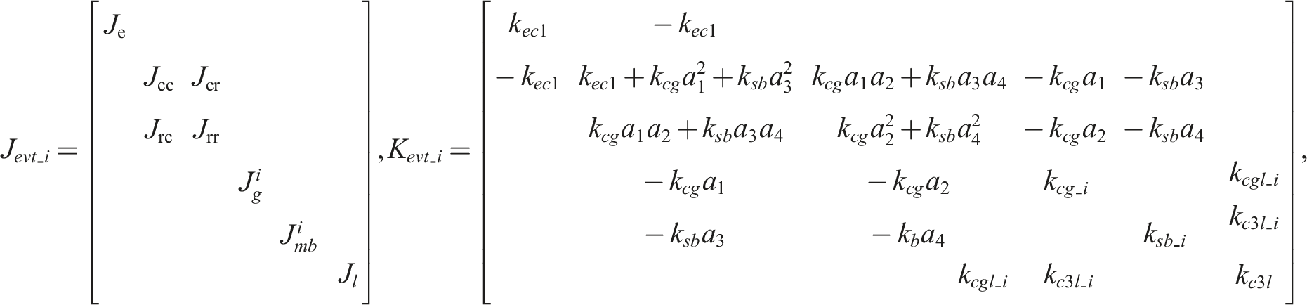
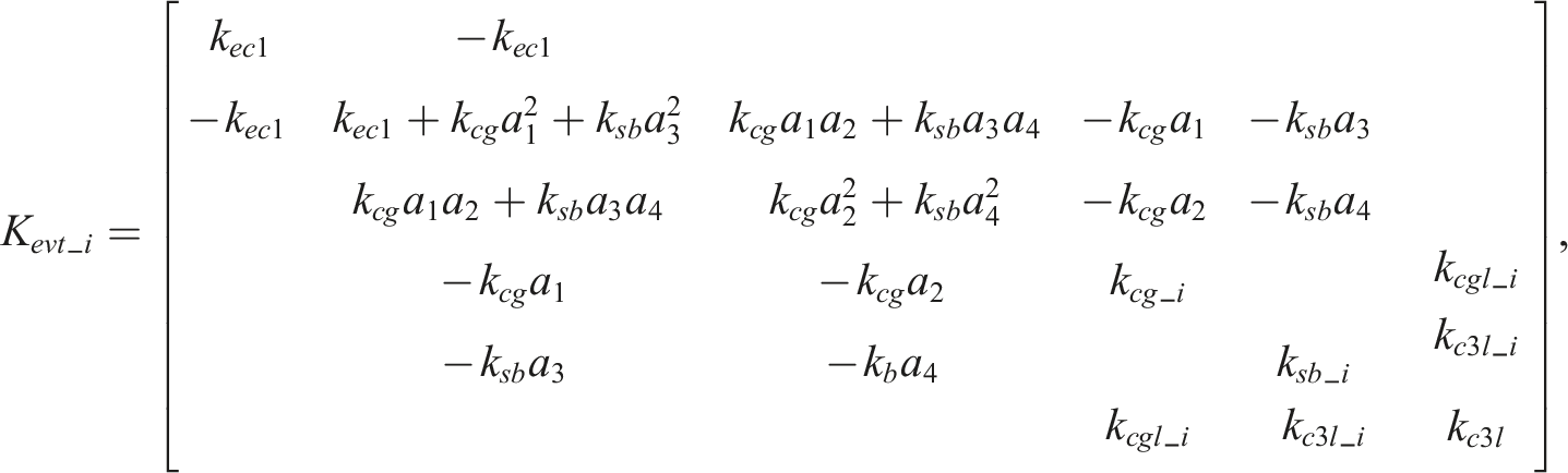
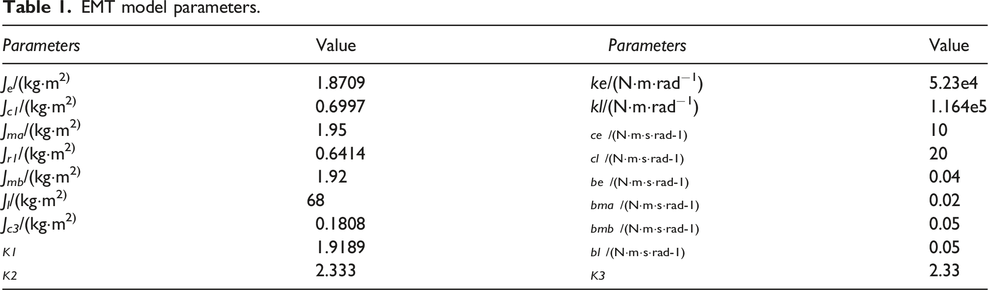
EMT model parameters.
External disturbance characteristics
The external input torque of EMT system is engine torque, motor torque and load torque, i.e. 
The disturbance excitation of external force torque of EMT system is mainly generated by engine and motor. The disturbance component has strong periodicity and persistence, which can be expressed in the form of Fourier series, as follows
The main frequency of engine excitation is
According to equation (11), the main harmonic frequency range of engine torque ripple is
L4 diesel engine is adopted, and the speed range is 840–2400r/min, f
Te
can be solved by equation (12), that is
Torsional vibration characteristics analysis
From the dynamic differential Eq. s of the system, the non-damping free vibration dynamic Eq. of the system can be obtained
The multi-DOF system has multiple natural frequencies and modes, and the free vibration is composed of several simple harmonic vibrations. Assuming that the solution is a harmonic vibration, the form is as follows
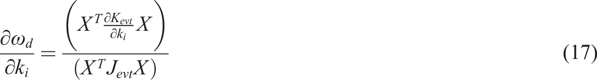
Incorporating equation (14) into equation (15), the following can be comprehended
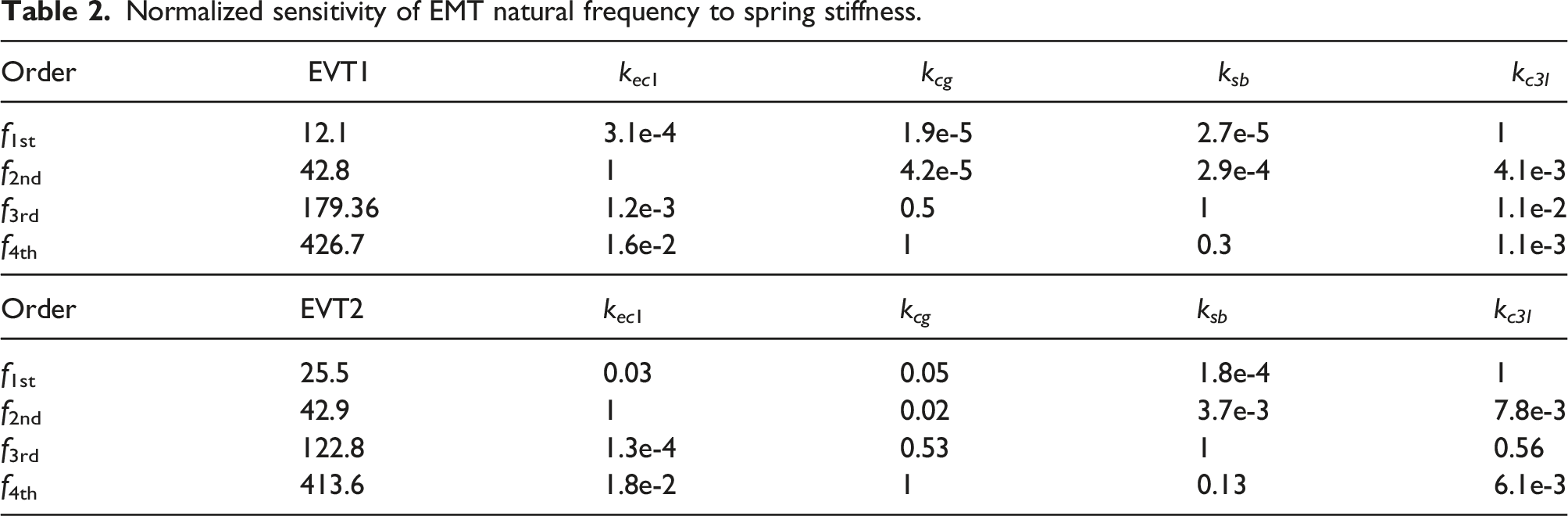
Normalized sensitivity of EMT natural frequency to spring stiffness.
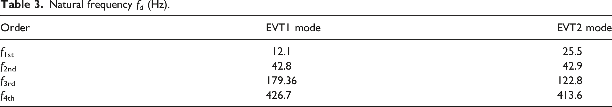
Natural frequency f d (Hz).
Assuming that EMT is only excited by engine torque and 
By introducing equation (18) into equation (8), the steady-state response is
By deriving equation (19) from time, it can be obtained that the speed response is
The amplitude frequency characteristic of speed to 
The amplitude frequency characteristics of speed response can be solved by bringing the data in table (1), as shown in Figure 2. Speed response excited by engine torque.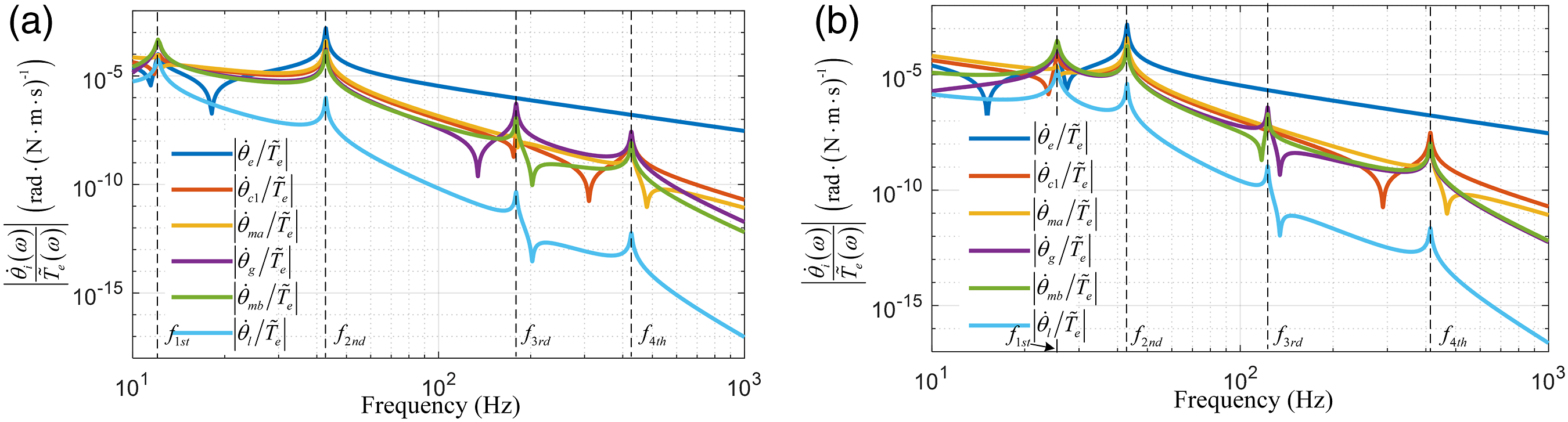
As can be seen from Figure 2, the vibration response of EMT system is mainly reflected in the low-frequency band, in which the peak value is reached at the first and second natural frequencies. For torque excitation above 100 Hz, although there are two resonance points, the amplitude response is much smaller than that in the low-frequency band, so the high-frequency component can be ignored.
For the EMT torsional vibration excited by engine crankshaft torque, the motor can be used as the control actuator to output electromagnetic torque and suppress the vibration response of the system. Analyzing the relationship between the torsional vibration state of the two motors and the torque ripple of the engine without torsional vibration control is of great significance to reasonably apply the motor control torque. The phase difference of vibration response of two motors can be expressed by the follows
The frequency characteristics of the phase difference between the two motors are shown in Figure 3. Motors phase difference frequency characteristics.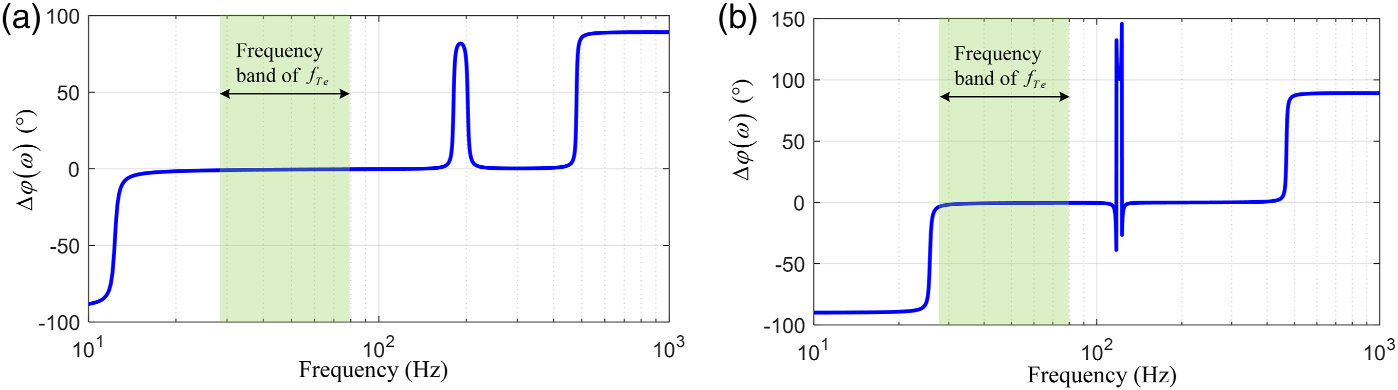
Figure 3 shows that the phase difference of motor response varies with the frequency of engine torque fluctuation. The most important thing is that in the main harmonic range of engine torque ripple (28 Hz–80 Hz), the phase difference of the speed fluctuation of the two motors is almost 0, which can be considered to be synchronous to a considerable extent. At the same time, it can be seen from Figure 3 that the amplitude response curves of the two motors basically maintain a fixed proportional relationship.
Electromechanical transmission torsional vibration state estimation
The torsional vibration state of EMT system is reflected in the speed of each rotating part, which is expressed in the form of slight fluctuation of speed. From the perspective of signal decomposition, the speed signal is composed of AC component, DC component and random measurement noise component, in which the dc term includes initial value term and trend term (first-order time function). Usually, the DC component and AC component of the speed signal can be estimated by using high pass and low-pass filters. However, the negative impact of the filter is that the estimated signal has phase lag. When the estimated signal is used in the real-time feedback system, the phase lag will affect the control effect and reduce the robustness of the system. Too large phase lag will lead to the instability of the system.
To reduce the phase lag and improve the estimation accuracy of vibration signal, a torsional vibration signal extraction method based on low-pass elimination DC is proposed
The DC component (mean value) in the speed signal represents the overall operation state of the system (including acceleration state), which can be described by the first-order time function, that is
The estimation of the speed measurement signal of time series can be described as a univariate linear regression model. Assuming that at time k, the measured signal of the speed sensor is 
The predicted value of average speed 
The predicted average speed is
The least square method is applied to estimate the parameters of the linear regression model, and the mean square error is selected as the loss function of the linear regression model, as follow equation
The least squares estimates of 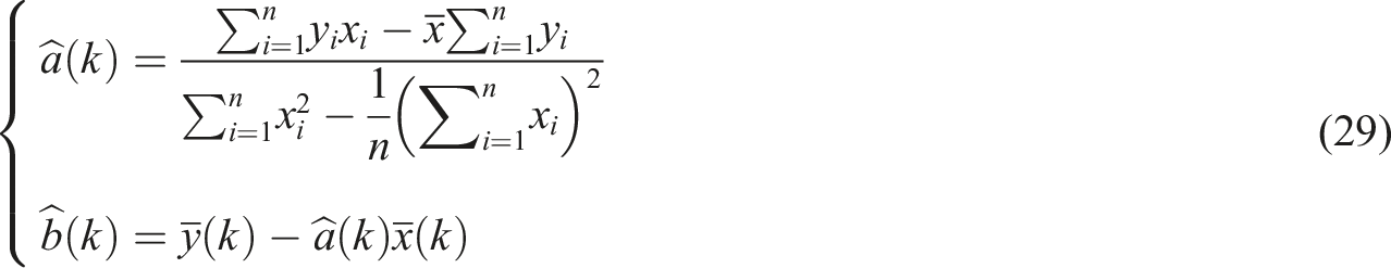
The regression equation is obtained according to the historical data, and the predicted value of the future time can be obtained by bringing in the coordinates of the future time. Since the sampling time ∆t is fixed, the operation of time coordinate can be eliminated. Assuming that time k is the origin of time coordinate, the width of sampling window is n and the prediction step is r, the regression curve and prediction value are shown in Figure 4. Univariate linear regression prediction model (with fixed sampling step).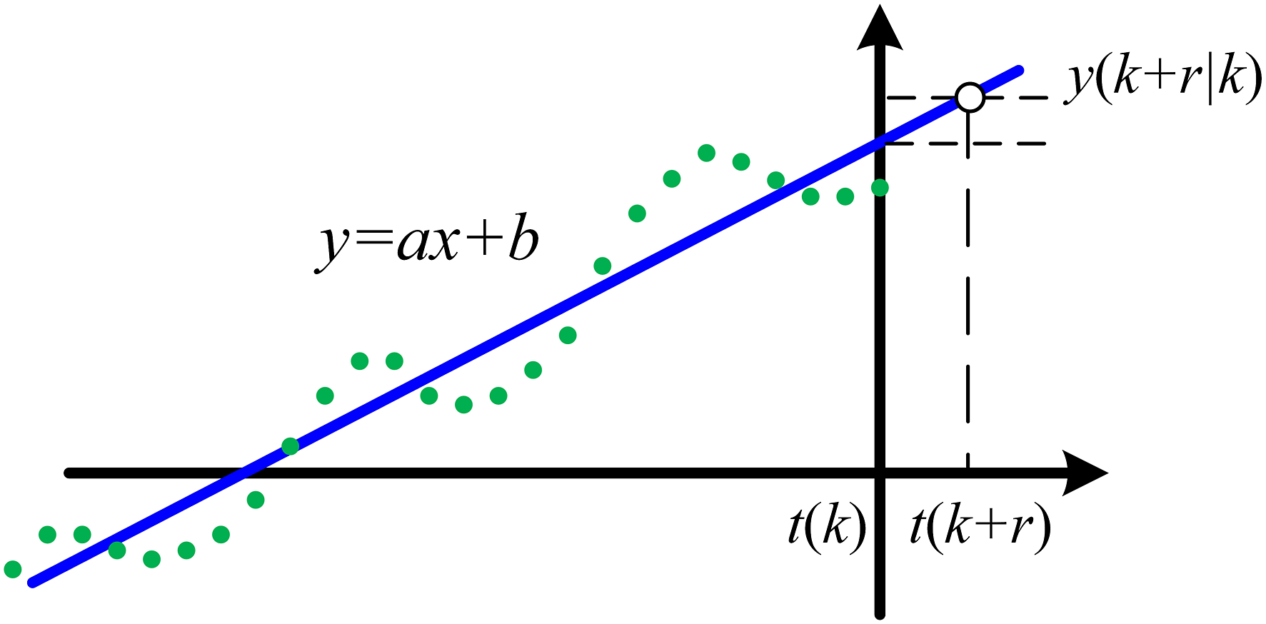
Substitute the sampling time ∆t, then
The average speed predicted in step r at time k is
equation (31) has the ability of prediction and estimation. When r =0, it is the estimation of the current time. From equation (30) and (31), the estimated value of the DC component of the current speed is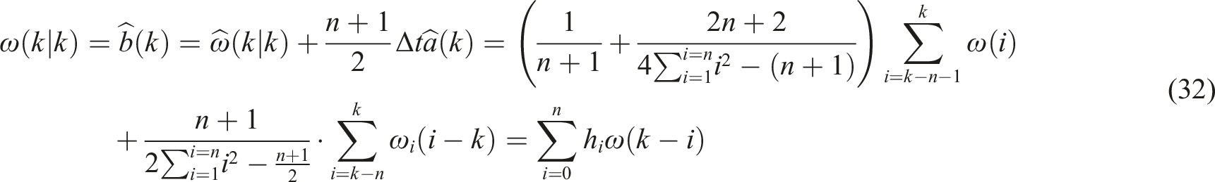
equation (31) shows that the estimation method of DC component estimated based on linear regression method has the form of FIR filter. By Z-transform of equation (31), it can be obtained that the discrete transfer function of the low-pass filter is
Set the sampling rate fs = 1024, n= 600. The amplitude frequency characteristics of Filter performance comparison.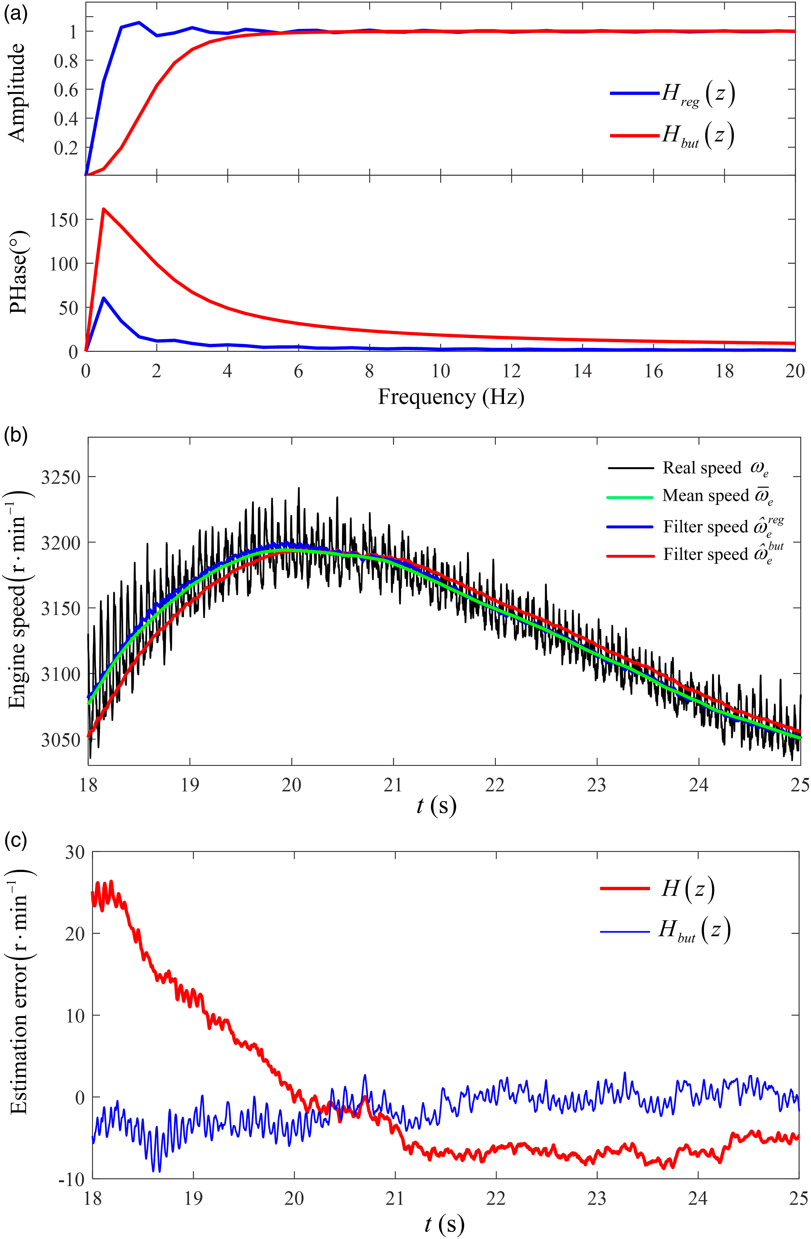
Figure 5(a) shows that compared with the conventional Butterworth high pass filter, the high pass filter constructed based on the linear regression method can accurately obtain the speed fluctuation signal, with small phase lag and good amplitude in the passband. It has a narrower transition band and small overshoot. There is a better phase advantage.
Figure 5(b) shows the experimental verification of the designed filter in the estimation of engine dynamic average speed. Compared with Butterworth filtering method,
Figure 5(c) shows the estimation error comparison of engine fluctuation speed, which shows that the designed high pass filter
Master-slave coupling control
Hierarchical control architecture
EMT control includes two control objectives. One is to adjust the torque value of each power element to achieve the target speed based on the motion state of the system rigid body so as to meet the power distribution and speed regulation requirements of the system; Second, based on the torsional vibration state, the additional motor dynamic torque is applied to suppress the torsional resonance amplitude of the system excited by the engine torque ripple. Therefore, the EMT system adopts a hierarchical control framework, as shown in Figure 6. The upper layer controls the reference control quantity of a given engine and motor. The lower level control performs speed and torque control of the engine and motor. EMT control block diagram.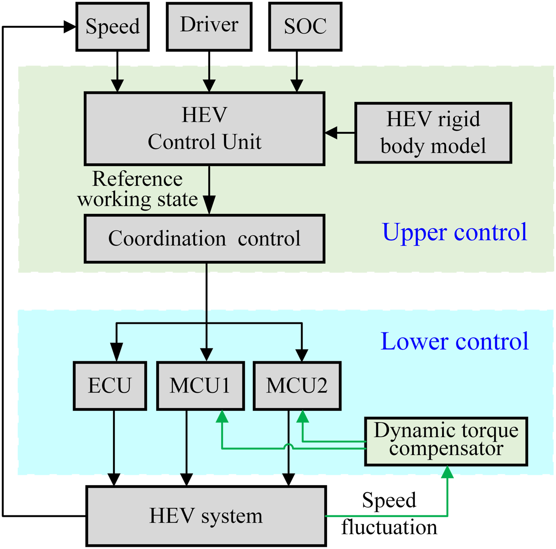
EMT system is a two input two output coupling system. The state trajectory is controlled by engine, motor A, and motor B. the system needs to design two governors to track the engine and drive motor to realize the speed tracking of the system.
The EMT speed closed-loop control structure with torsional vibration control loop is shown in Figure 7. EMT speed closed-loop control structure with torsional vibration control loop.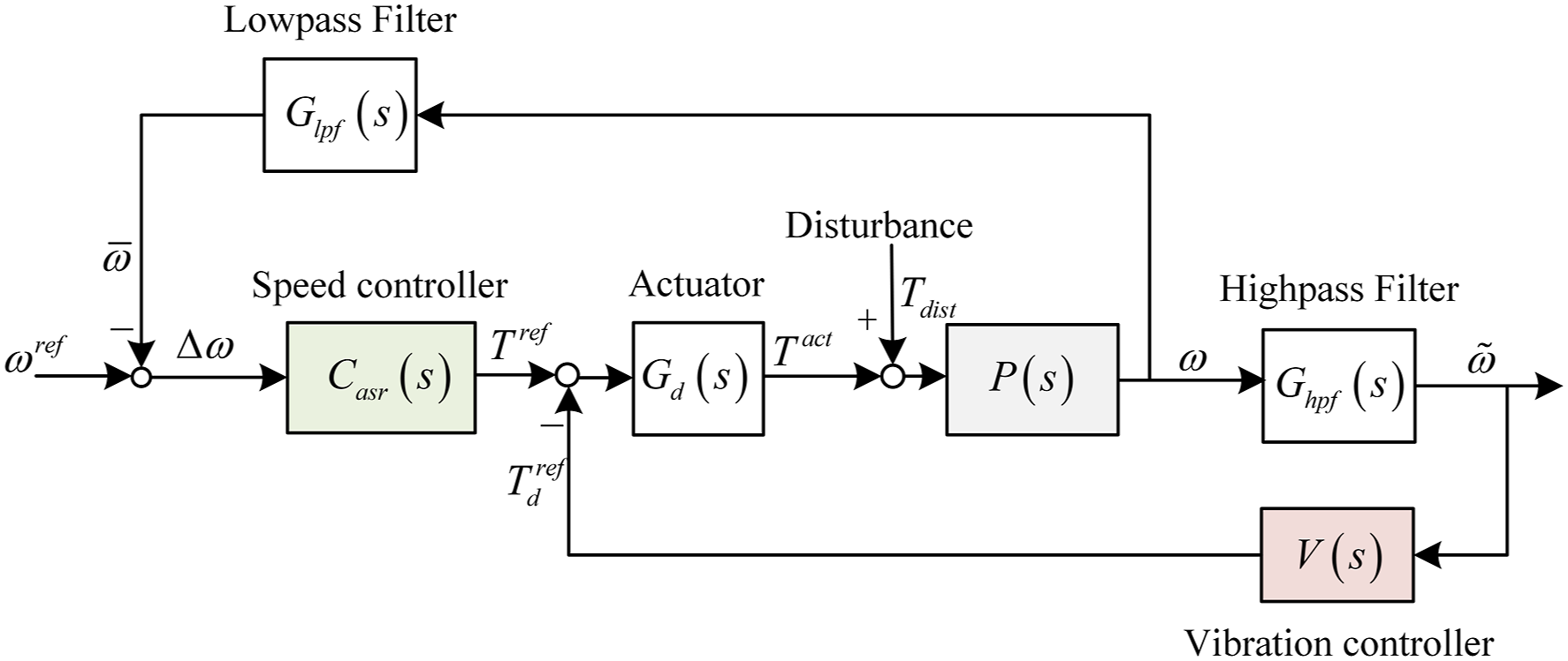
In the Figure 7, 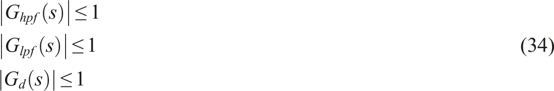
Sensitivity analysis of controllers
It can be seen from Figure 7 that in the closed-loop speed regulation system, the transfer function from 
The sensitivity of 
The sensitivity of 
Define the relative sensitivity of speed control 
It is known from equation (34) that
Assume that 
Note 1:
The transmission from torque disturbance 
The sensitivity of 
The sensitivity of 
Define the relative sensitivity of vibration control 
Let s=jω, then
Eq. (45) satisfy the following relationship
Note 1:
Combined with Note 1 and Note 2: when the frequency of engine torque fluctuation is large, speed regulation control and torsional vibration control are independent of each other. Therefore, the control parameters do not affect each other.
Master-slave coupling control
Figure 4 shows that in the frequency domain of engine primary and secondary excitation, the two motors have considerable synchronization and basically maintain a fixed proportional relationship. Therefore, the master-slave control method (M-SAC) is adopted. The torque of one motor is the dominant torsional vibration control torque and the torque of the other motor is the subordinate control torque. The two motors are master-slave relationship with each other, as shown in Figure 8. The M-SAC method mainly considers the following facts: (1) The traditional feedforward compensation control requires the accurate measurement of torque ripple and the analysis of dynamic characteristics. These requirements are often difficult to meet in reality. In the real working environment, the speed signal is the most easily obtained and trustworthy system state measurement signal. Feedback control using speed signal is the basic means of EMT torsional vibration suppression. (2) The measured signals of rotational speed and its differential contain abundant information of torsional vibration state of the system. (3) In the low-frequency torsional vibration region, the response of the two motors to the engine excitation is synchronous, and the master-slave control can ensure the timing of the control force of the two motors, which has advantages in the anti-interference of the controller. (4) From the view of dynamic topology, the synchronization and timing of master-slave control method is like virtual lever, which increases the internal force channel of the system. (5) From the coupling point of view, the master-slave control method establishes the state coupling constraint between the two motors through speed feedback, increases the force coupling channel independent of the planetary gear set, and provides a new possibility for torsional vibration suppression. Master-slave control (MSAC) block diagram.
Assumed that the speed of the system reaches the balance point of the rigid body and the speed regulating torque has no fluctuation, that is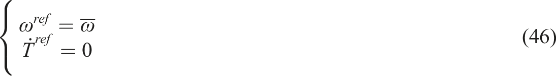
If equation (46) is satisfied, only torsional vibration control is considered, and speed regulation control can be ignored.
Assuming that MGa is dominant, MGb is subordinate, which satisfies the following Eq.
As shown in Figure 8, the torsional active control torque T ma and T mb act as a virtual lever u in the system, so the coefficient K ab is defined as the lever ratio.
Assuming that the dominant motor control adopts PD control, then
If the dynamic excitation torque of the engine is 
Control parameters characteristics
Let w(t)=0 in equation (49), the closed-loop dynamic characteristics of the MSAC can be obtained. The characteristics of the system are determined by the leverage ratio K
ab
, the proportional coefficient K
p
, and the differential coefficient K
d
. When K
p
=0.3 and K
d
=3, the effect of the lever ratio on the natural frequency of the system is calculated as shown in Figure 9 and Table 4. The natural frequency varies with Kab. Coordinates of frequency curve intersection (K
ab
, f).
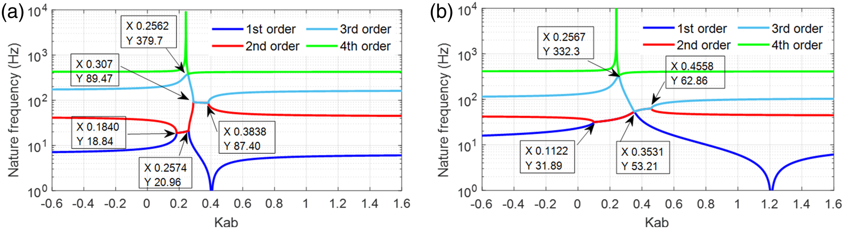
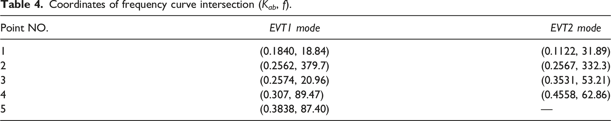
Figure 9 shows that in EVT1 mode, with the increase of K ab , the 1st and 2nd order natural frequencies coincide at No.1 point and separate at No.3 point. The 3rd and 4th order natural frequencies intersect at No.2 point. The 2nd and 3rd order natural frequencies intersect at No.4 point and separate at No.5 point. At No.4, the 2nd and 3rd order natural frequencies coincide, and the 2nd order natural frequency reaches 89.47 Hz, which is very effective for improving the low-frequency torsional vibration of the system.
In EVT2 mode, with the increase of K ab , the 1st and 2nd order natural frequencies coincide at No.1 point and separate at No.3 point. The 3rd and 4th order natural frequencies intersect at No.2 point. The 2nd and 3rd natural frequencies intersect at No.3 point and separate at intersection No. Four point. Between No.3 point and No.4 point, the 1st natural frequency of the system is eliminated, and the lower frequency value is larger, which is more effective for improving the low-frequency torsional vibration of the system.
Therefore, the natural frequency of the system changes significantly with the change of K ab , and there is a parameter region where the torsional vibration order decreases. Reasonable lever coefficient value can eliminate the one order natural frequency and improve the dynamic characteristics.
The variation of system natural frequency with differential coefficient K
d
is shown in Figure 10 and Table 5. In this case, the controller parameters are set as K
ab
=0.1 and K
p
= 0.3. the natural frequency changes significantly with the increase of K
d
, and there is a parameter region where the torsional vibration order decreases. The natural frequency varies with Kd. Coordinates of frequency curve intersection (K
d
, f).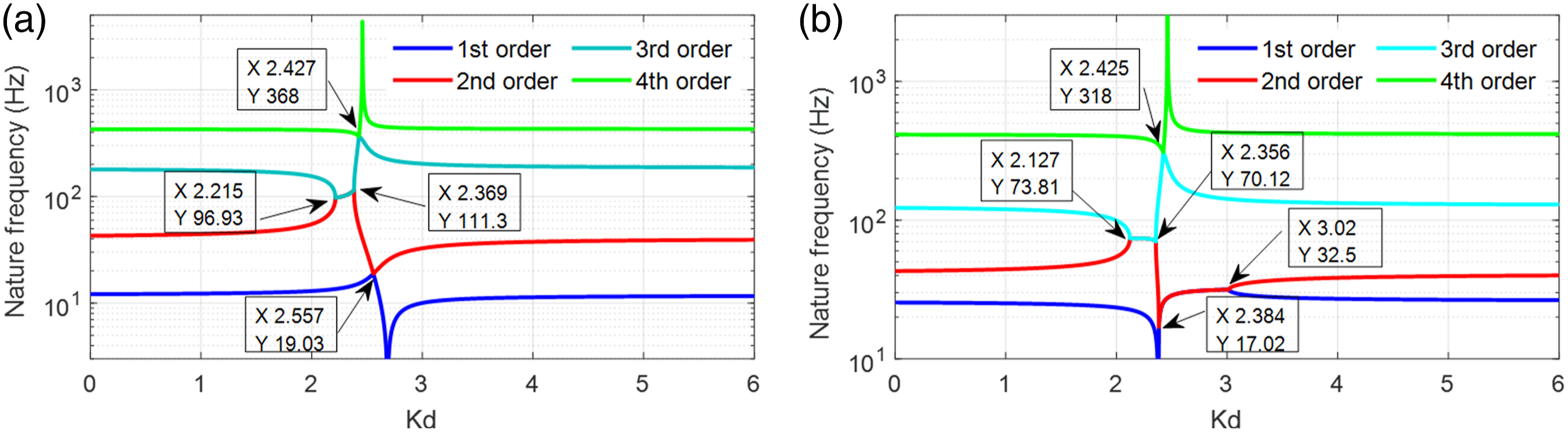
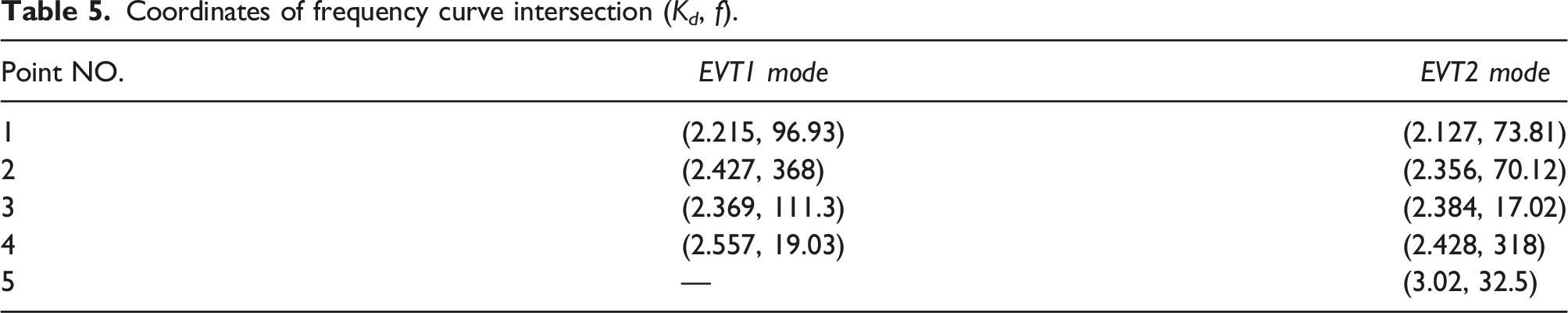
Figure 10 (a) shows that in EVT1 mode, with the increase of k d , the 2nd-order modal frequency curve and the 3rd-order modal frequency curve coincide at Point 1 and separate at Point 3. Therefore, when k d is located in the region (2.215,2.369) the resonance in the midfrequency (100–300 Hz) of the system is reduced by one. The 1st-order modal frequency curve and the 2nd-order modal frequency curve coincide at Point 4. Therefore, when k d =2.557, the resonance in the low-frequency (≤100 Hz) of the system is reduced by 1. The 3rd-order modal frequency curve and the 4th-order modal frequency curve coincide at Point 2. Therefore, when k d =2.427, the resonance in the highfrequency (≥300 Hz) of the system is reduced by 1. Therefore, k d plays a significant role in improving the EVT1 mode vibration characteristics of the system.
Similarly, as can be seen from Figure 10(b), in EVT2 mode, with the increase of k d , the 2nd-order modal frequency curve and the 3rd-order modal frequency curve coincide at Point 1 and separate at Point 2. Therefore, when k d is located in the region (2.127,2.356) the resonance in the midfrequency (100–300 Hz) of the system decreases by 1. The 1st-order modal frequency curve and the 2nd-order modal frequency curve coincide at Point 3 and separate at Point 5. Therefore, when k d is located in the region (2.384,3.02) the resonance in the low-frequency (≤100 Hz) of the system is reduced by 1. The third-order modal frequency curve and the fourth-order modal frequency curve coincide at Point 4. Therefore, when k d =2.425, the resonance in the highfrequency (≥300 Hz) is reduced by 1. Therefore, k d plays a significant role in improving the EVT2 mode vibration characteristics of the system.
In brief, Figure 10 shows that reasonable differential coefficient K d can eliminate the first natural frequency and improve the dynamic characteristics.
The variation of the natural frequency of the system with the proportional coefficient K
p
is shown in Figure 11. In this case, the controller parameters are set as K
ab
=0.1, K
d
=2. The natural frequency varies with Kp.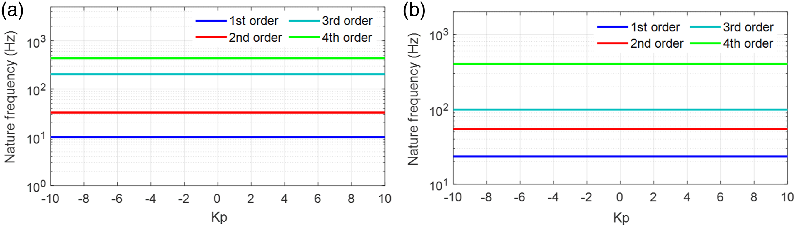
Figure 11 shows that the differential coefficient K p does not change the value of the natural frequency of the system, but only affects the response amplitude of each natural frequency.
Comparing with Figure 9, Figure 10, and Figure 11, it can be seen that the influence of master-slave coupling control method on the torsional vibration response of EMT system is determined by the leverage coefficient K ab , the proportional coefficient K p and the differential coefficient K d . The leverage coefficient K ab and the differential coefficient K d can change the natural frequency of the torsional vibration.
Reasonable control parameters can reduce the torsional vibration of EMT. The optimal control parameters are K p =0.3, K d =3, K ab_evt1 =0.268, and K ab_evt2 =0.31.
Independent mode space optimal control (IMSOC)
In order to highlight the vibration reduction performance of MSAC, this paper also designs the optimal control method based on IMSOC. 40 And the simulation results are compared.
Make a linear transformation to the equation (8). Let Q=0. The natural frequencies f
i
and mode shapes Φ
i
are obtained. Substituting the system mode matrix to transform 
The following Eq. is obtained
Further transformation
The above Eq. is transformed into a decoupled state Eq. about the state vector z in the modal space
The matrix is partitioned according to the modal order, where
The output Eq. is as follows

The linear quadratic performance Eq. is selected as
The i-th mode control quantity is
When 
Take equation (59) into equation (57)

The control block diagram of IMSOC is shown in Figure 12. Control block diagram of IMSOC.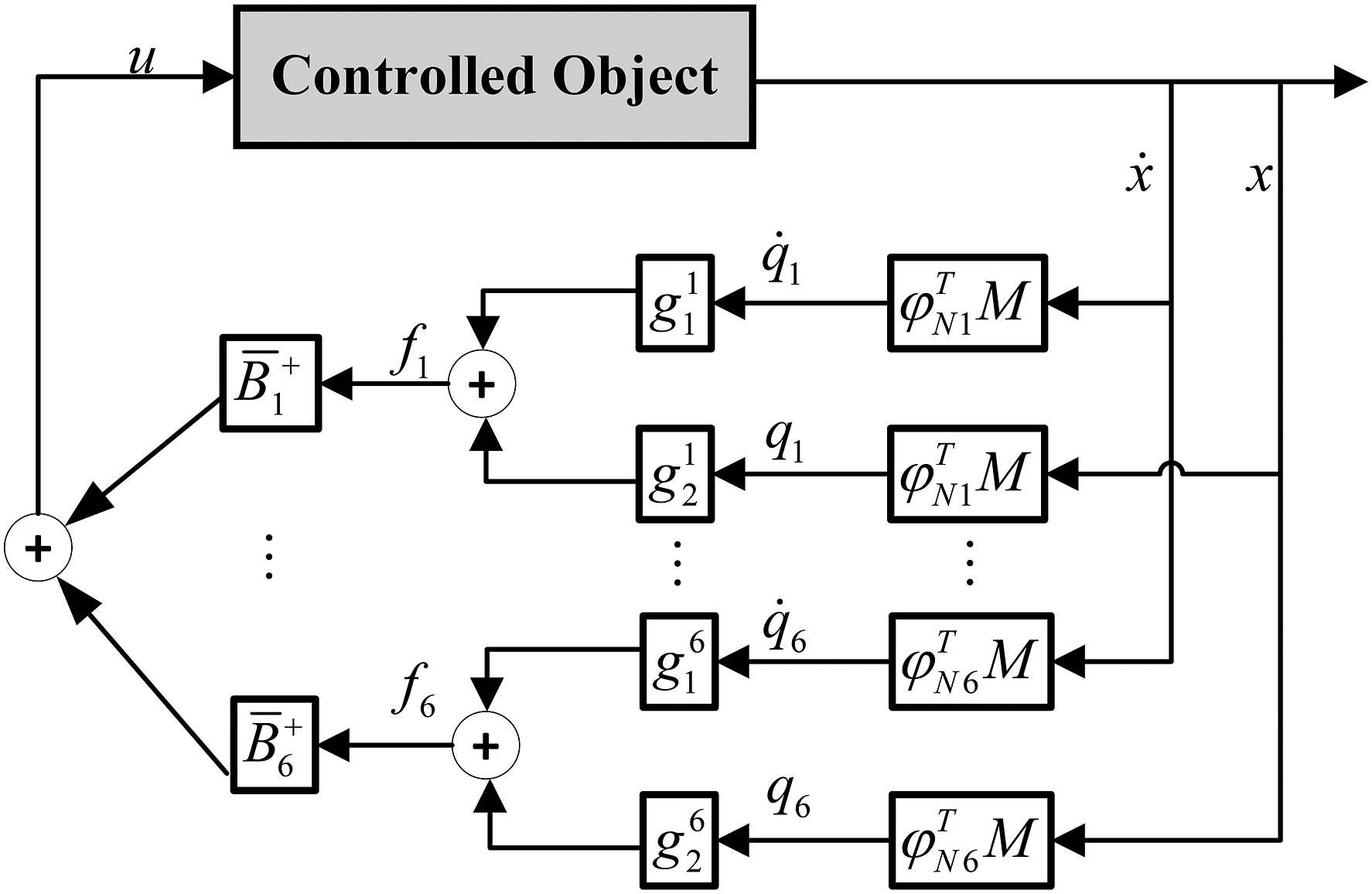
Closed-loop speed response characteristics
To verify the theoretical findings and the effectiveness of vibration active control, the closed-loop speed response characteristics are compared. The parameters of MSAC are set to K p =0.3, K d =3, K ab_EVT1 =0.267, and K ab_EVT1 =0.3. In contrast, the IMSOC is utilized to suppress the 1st order and 2nd order torsional vibration modes. The control objectives of master-slave motor active control (MSAC) and optimal mode space control (IMSOC) are to reduce the resonance peak at low frequency.
The control objectives of MSAC and IMSOC are to reduce the resonance peak in the low-frequency region. The amplitude frequency characteristics of vibration angular velocity response of each independent degree of freedom of EMT under engine pulsating torque excitation are shown in Figure 13. Speed response characteristics excited by engine torque Te.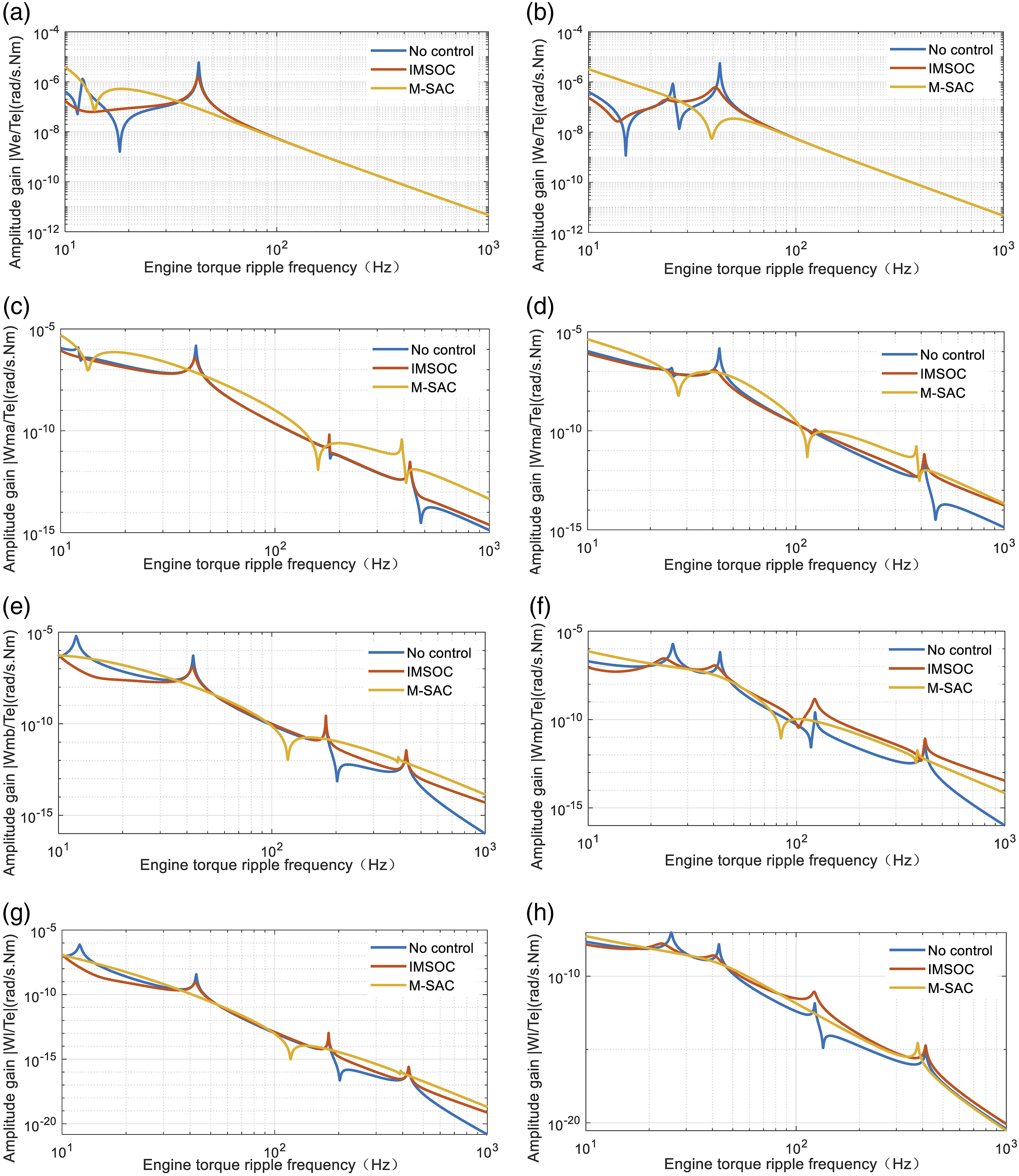
Figure 13 shows that EMT system has four order torsional vibration modes in the two working modes, and the natural frequencies of each mode are listed in Table 1. In the low-frequency region, the torsional vibration response peaks of the 1st and 2nd modes are extremely large, which is the main factor to deteriorate the ride comfort performance of the system.
Compared with the EMT without control, the IMSOC algorithm is only effective for the controlled mode, which not only attenuates the response amplitude, but also reduces the resonance frequency, so that the vibration response peak of the first and second modes is obviously suppressed. At the same time, the first frequency is reduced from 12.1 Hz to 9.4 Hz, and the second frequency is reduced from 42.8 Hz to 42.3 Hz. For the uncontrolled frequency region (the third and the fourth mode), although the vibration response of the system increases, the amplitude is small, so the contribution to the system response is tiny.
Compared with the EMT without control, the MSAC algorithm reduces the resonance points of two low-frequency ranges, and makes the amplitude attenuation within 500 Hz very smooth. There is no obvious peak point, which is very good for EMT system torsional vibration peak clipping.
Compared with the IMSOC algorithm, the MSAC algorithm has better peak clipping effect and great application potential.
Experimental results
To verify above control algorithm, tests on the torsional vibration are carried out on the real EMT test bench. The testing system is given in Figure 14. Bench test layout.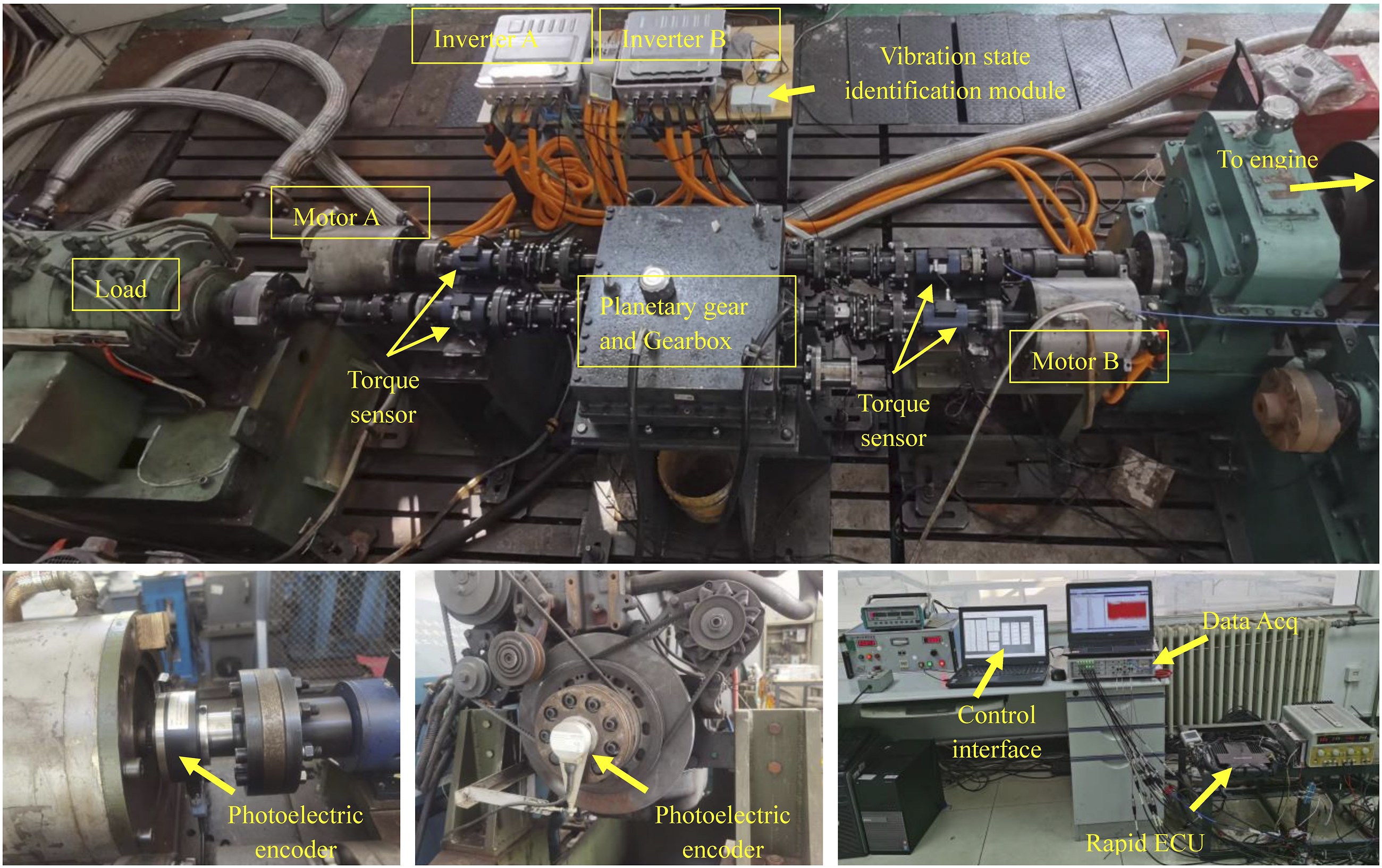
The sensor obtains the speed and torque information of the measured shaft at the same time and outputs a pulse signal with variable frequency. The pulse signals then are transformed through data lines into the multichannel data acquisition. After that, the responses of torsional vibration and the shafting speed signals can be obtained using LMS. TEST.LAB. To apply vibration feedback control, the speed data is filtered to obtain the vibration state information. The motor controller receives the reference torque signal and speed fluctuation signal, generates the dynamic control signal, and then sends it to the inverter, which outputs the armature current to generate the motor torque.
The test includes two parts, the coordinated speed regulation without torsional vibration control and with control. The test reference is an engine deceleration process of EVT2 mode when medium load conditions, T
l
= 500Nm. The test duration is 200s. The initial engine speed is 2000rpm and end process speed is 500rpm. The test conditions are shown in Figure 15. The reference speed and control conditions.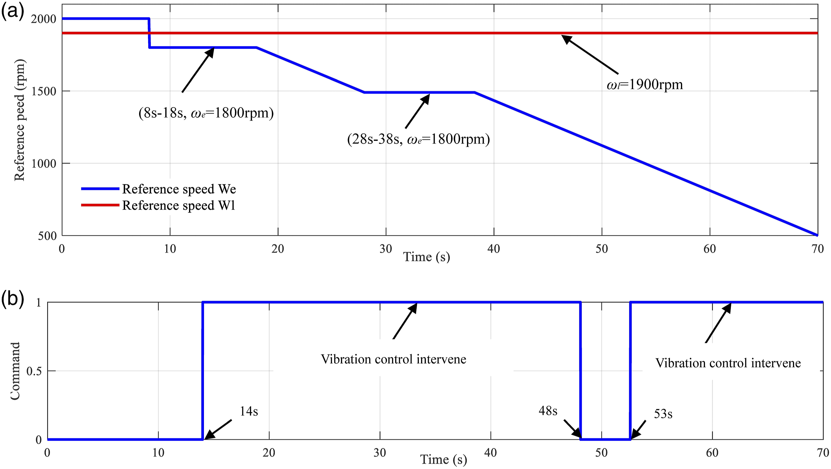
In comparison, Figure 16 shows the bench test results using the master-slave motor active control (MSAC) for torsional vibration suppression. It is clearly observed that during the change of target speed, the engine angular speed ω
e
as well as the load mass speed ω
l
can quickly track new target points. Test results.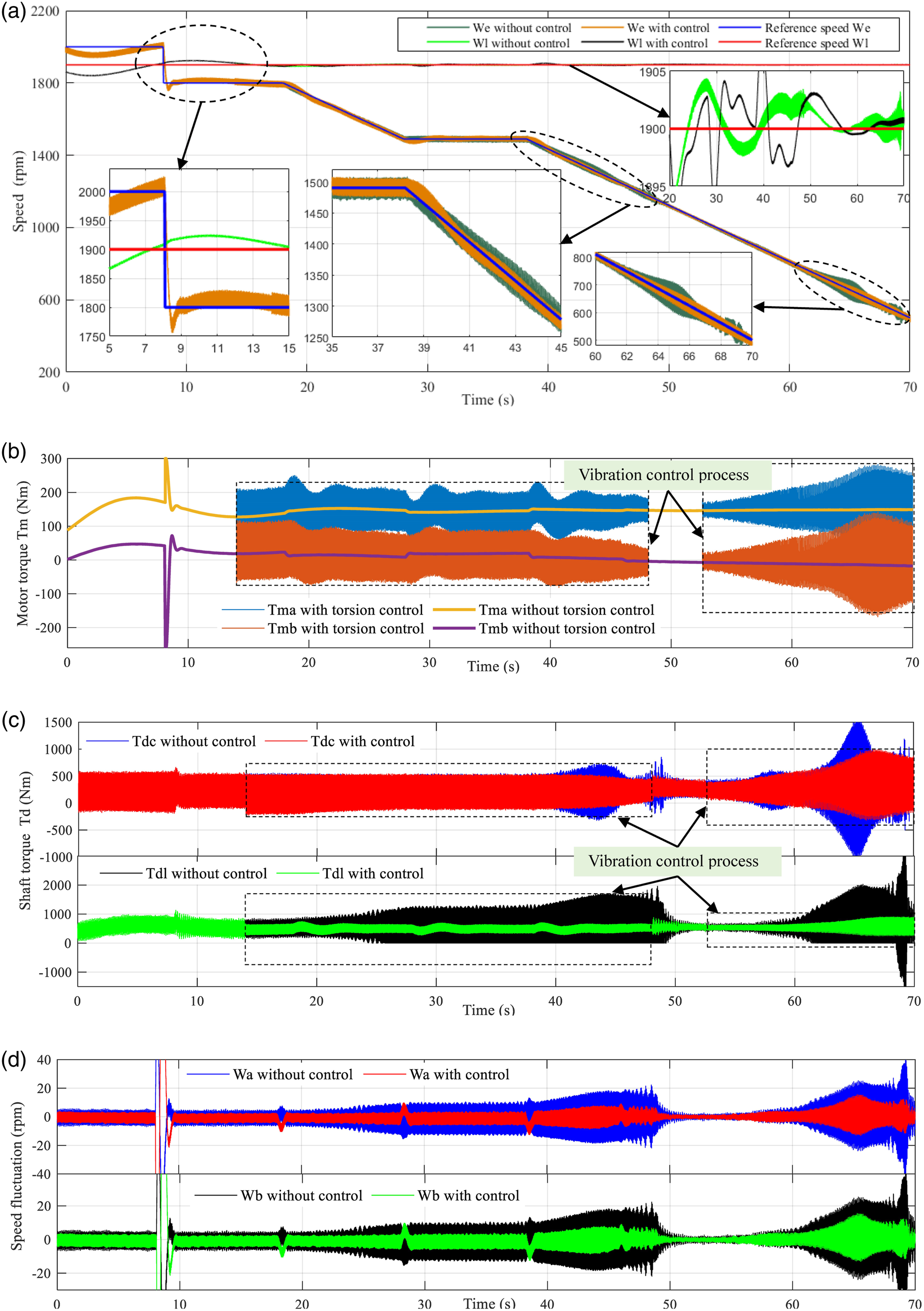
A comparison in Figure 16(a) and Figure 16(d) implies that torsional vibrations may be effectively addressed by the double-motor speed coupling control loop. Active torsional vibration control can reduce the speed fluctuation at each port of EMT, especially in the resonance region.
The comparison in Figure 16(b) shows that the application of dual motor speed coupling feedback to control torsional vibration will cause large electromagnetic torque fluctuation of the motor. The higher the degree of suppression of fluctuations in the speed oscillation area, the greater the motor oscillation torque.
The comparison in Figure 16(c) shows that the effect of active torsional vibration control is different for different parts of EMT, and the damping effect for load mass is very good, but it is very limited for the engine. This result is reasonable because the clutch shaft is located at the front end of the vibration transmission path, and the motor control torque is calculated without adding engine speed feedback.
Conclusions
This paper analyzes and derives the mathematical models of EMT system and the bench experiment is performed. The results show that the EMT system contains four torsional modes in the low-frequency region, which have a great impact on the NVH performance of the system, among which the 1st order and 2nd order torsional mode resonance make the largest contribution. The torsional vibration suppression effect based on master-slave control is closely related to the influence of leverage coefficient K ab and feedback coefficient K p and K d . The influence of master-slave coupling control method on the torsional vibration response of EMT system is determined by the leverage coefficient K ab , the proportional coefficient K p and the differential coefficient K d . The leverage coefficient K ab and differential coefficient K d can change the natural frequency of torsional vibration of the system, which has the ability of “frequency shift.” The master-slave motor control algorithm can effectively solve the problem of torsional vibration. Active torsional vibration control can reduce the speed fluctuation of each port of EMT, especially in the resonance region. The higher the fluctuation suppression degree in the speed oscillation region, the greater the motor oscillation torque.
Footnotes
Declaration of conflicting interests
The author(s) declared no potential conflicts of interest with respect to the research, authorship, and/or publication of this article.
Funding
The author disclosed receipt of the following financial support for the research, authorship, and/or publication of this article: This work was supported by the National Natural Science Foundation of China (52130512).