In this study, the Integral Resonant Controller (IRC) is presented along with the Proportional-Derivative (PD) controller as a novel control technique to control the dynamical behaviors of the 12-pole rotor active magnetic bearing system. According to the proposed control strategy, the system model has been derived as a two-degree-of-freedom nonlinear dynamical system coupled with two first-order filters. The obtained mathematical model has been analyzed utilizing the asymptotic analysis. The nonlinear algebraic system that governs the steady-state vibration amplitudes and corresponding phase angles of the considered system has been extracted. The influence of the IRC control parameters on the rotor dynamics has been explored by plotting the different bifurcation diagrams. The analytical investigations demonstrated that the vibration suppression efficiency of the combined controller (i.e., PD and IRC) is proportional to the product of control and feedback gains of the IRC as well as the derivative gain of the PD-controller. In addition, it is found that the controller efficiency is inversely proportional to both the square of the internal loop feedback gain of the IRC and the position gain of the PD-controller. Accordingly, an objective function has been derived to design the best control gains of the proposed controller strategy. The analytical and numerical simulations confirmed that the suggested control method can suppress the system vibration and eliminate the catastrophic bifurcation behaviors if the control gains are selected according to the proposed objective function. Finally, the effect of failing one of the coupled integral resonant controllers on the rotor dynamics has been explored as a precautionary procedure. It is found that the failure of one of the coupled integral resonant controllers may breakdown the bifurcation symmetry of the rotor system, but the system does not lose its stability.
The magnetic bearings system is one of the best suspension systems for rotating shafts. Its working principle is based on generating a balanced electromagnetic force to suspend the rotor in its hovering attitude without any contact with the stationary parts. The suspension of the shafts without physical contact provides the magnetic bearings system with many advantages over the other conventional suspension systems such as operation with high speed, frictionless operation, lubrication is not required, low failure rate, less maintenance, high reliability, and high durability. As a result, numerous research papers have been devoted to investigate the dynamical characteristics of various magnetic bearing configurations, as well as the many control methodologies that have been introduced. Ji et al.1 studied the four-pole configuration of the magnetic bearings system. They investigated the considered model as an autonomous and non-autonomous system. They found that the investigated model shows a variety of nonlinear behaviors, including Hopf, saddle-connection, and saddle-node bifurcations. The six-pole configuration of the magnetic bearing system has been investigated with two different control methodologies by Saeed et al.2,3 They presented two control techniques based on the Cartesian displacement and velocity of rotor lateral oscillations.2 In addition, they introduced a proportional-derivative control algorithm based on the polar displacement and polar velocity of the rotating shaft. According to the studied control methods, they reported that the Cartesian-based controller has high efficiency than the polar-based one in reducing the system oscillations. However, the polar-based control method is more stable than the Cartesian-based one. The eight-pole configuration has received many analyses and control techniques.4–14 Ji and Hansen4 used a traditional PD-controller to reduce the undesired vibrations of an eight-pole system at the primary resonance condition. The suggested configuration model has been derived as a nonlinear two-degree-of-freedom dynamical system. The asymptotic analysis has been applied to explore the static bifurcation behaviors of the rotor system. They concluded that the system may exhibit simultaneous bi-stable, or tri-stable solutions depending on the rotor angular velocity. Ji and Leung5 studied the static bifurcation for the same model studied in Ref.[4] but at the superharmonic resonance condition. Yang et al.6 discussed the oscillation modes of the eight-pole system using the energy and phase angle methods. They found that the system can perform one of two vibration modes, which are the quasiperiodic and elliptic motions. El-Shourbagy et al.7 investigated the vibration control of the eight-pole system utilizing a nonlinear form of the PD-controller. They illustrated analytically and numerically that the nonlinear PD-controller is more efficient than the linear one. Saeed et al.8 investigated a discontinuous dynamical model for the eight-pole system, where the rub-impact force among the rotor and the electromagnetic poles are included in the proposed model. They reported that the system can vibrate with periodic, quasiperiodic, or chaotic oscillations depending on the impact stiffness coefficient as well as the dynamic friction coefficient. Zhang et al.9–14 introduced a PD-controller with time-varying proportional gain to control the eight-pole magnetic bearings system. The system mathematical model has been derived as a time-varying dynamical system with two degrees of freedom based on the proposed control method. Then, they investigated the proposed model with different analytical and numerical methods. The introduced analysis showed that the studied time-varying model may perform multipulse chaotic behavior. Recently, El-Shourbagy et al.15 studied the twelve-pole magnetic bearings configuration. They applied the traditional linear position-velocity controller as an active control strategy to suppress the system’s lateral oscillations. According to the introduced analysis, they found that the position control gain has a significant impact on the dynamical characteristics of the system. In addition, it is found that the system can exhibit chaotic and quasiperiodic oscillations besides the periodic ones. Saeed and Kandil16 explored the steady-state bifurcation behaviors of the sixteen-pole configuration. They proposed two control algorithms based on the PD-controller to improve the rotor dynamics. The first control strategy has been established based on the rotor Cartesian vibrations in the plane, while the second control method has been designed according to the rotor radial oscillations. According to the introduced analysis, they reported that the system may have simultaneous bi-stable, tri-stable, or quadric-stable periodic oscillations depending on the rotor angular velocity in the case of the first control strategy, while the system can perform simultaneous bi-stable solutions only in the second control method. Zhang et al.17–21 studied a time-varying dynamical model for the sixteen-pole configuration, where the position-velocity controller with time-varying coefficients has been utilized to control the system’s undesired vibrations. The controllability, durability, and reliability of the active magnetic bearings system have encouraged many scientists and engineers to utilize such systems with some adaptive control techniques to serve as smart actuators.22–27 Ishida and Inoue22 utilized a four-pole magnetic bearings system with the push-pull mechanism to control the undesired oscillations of a Jeffcott rotor system supported by the traditional bearings. Saeed et al.23–27 applied various control algorithms to control the lateral oscillation of conventionally supported rotating shafts employing the magnetic bearings system as an actuator. Finally, Srinivas et al.28 summarized the different usages of the magnetic bearings system regarding the flexible rotor dynamics.
One of the efficient control approaches that have been widely used to reduce the nonlinear oscillation of various dynamical systems is the Integral Resonant Controller (IRC). IRC is a first-order filter that is linearly coupled to the targeted oscillatory system to dampen these unwanted oscillations.29–36 Diaz et al.,29 and Al-Mamun et al.30 employed the IRC to reduce the nonlinear vibrations of a light-weight smart structure, where the authors reported that the IRC has vibration suppression performance higher than the conventional control methods. MacLean and Sumeet31 and Omidi and Mahmoodi32 applied a nonlinear version of the IRC to reduce the transversal oscillation of a cantilever beam. Omidi and Mahmoodi33,34 utilized a combination of both the IRC and PPF controller to enhance the control efficiency of the PPF controller. Saeed et al.35 utilized a time-delayed nonlinear IRC to control the parametric oscillation of a cantilever beam system. The authors concluded that the optimal design for the control parameter can not only mitigate the system oscillations to an acceptable limit but also it can eliminate the system vibrations. Despite the IRC’s high efficiency in suppressing unwanted oscillatory motion in many dynamical systems, it has never been used to suppress the nonlinear oscillations of a 12-pole active magnetic bearings system.
Based on the above discussions, one can notice that the nonlinear vibration control of the twelve-pole magnetic bearing system has not been studied before (except in Ref.[15]). However, this type of magnetic bearing has several advantages over other configurations, including high dynamic stiffness, low power consumption, a negligible cross-coupling effect, and better suspension behaviors.37 As a result, a new control algorithm consists of both the IRC and PD-controllers is proposed within this article to control the unwanted lateral oscillations of the twelve-pole system. According to the proposed controller, the system mathematical model has been established as two nonlinear second-order differential equations coupled to two linear first-order differential equations. Then, the obtained dynamical system has been investigated by applying perturbation methods. Many Perturbation techniques have been applied in the literature to derive the amplitude-frequency relationship of different nonlinear dynamical systems. For example, the multiple time-scales perturbation technique38,39 has been applied extensively to investigate nonlinear oscillatory systems with ordinary derivatives. In addition, Chinese mathematician Prof. He et al.40–42 introduced modified versions of the homotopy perturbation method to analyze different classes of nonlinear oscillators. Recently, Prof. He et al.43 introduced a simple analytical technique relying on the homotopy perturbation method to analyze the fractal oscillators. In this study, the multiple time-scale perturbation method is applied to investigate the dynamical behaviors of the considered system. The corresponding nonlinear algebraic equations that govern the steady-state motions are extracted. Then, the influence of all control parameters on the static bifurcation behaviors of the rotor system is explored through the different response curves. In addition, the system transient response is also investigated by solving the equations of motion numerically. The obtained results demonstrated that the introduced control method is more efficient than the traditional PD-controller, where a new objective function has been introduced to design the optimum control gains.
Nonlinear dynamical equations of the 12-pole system
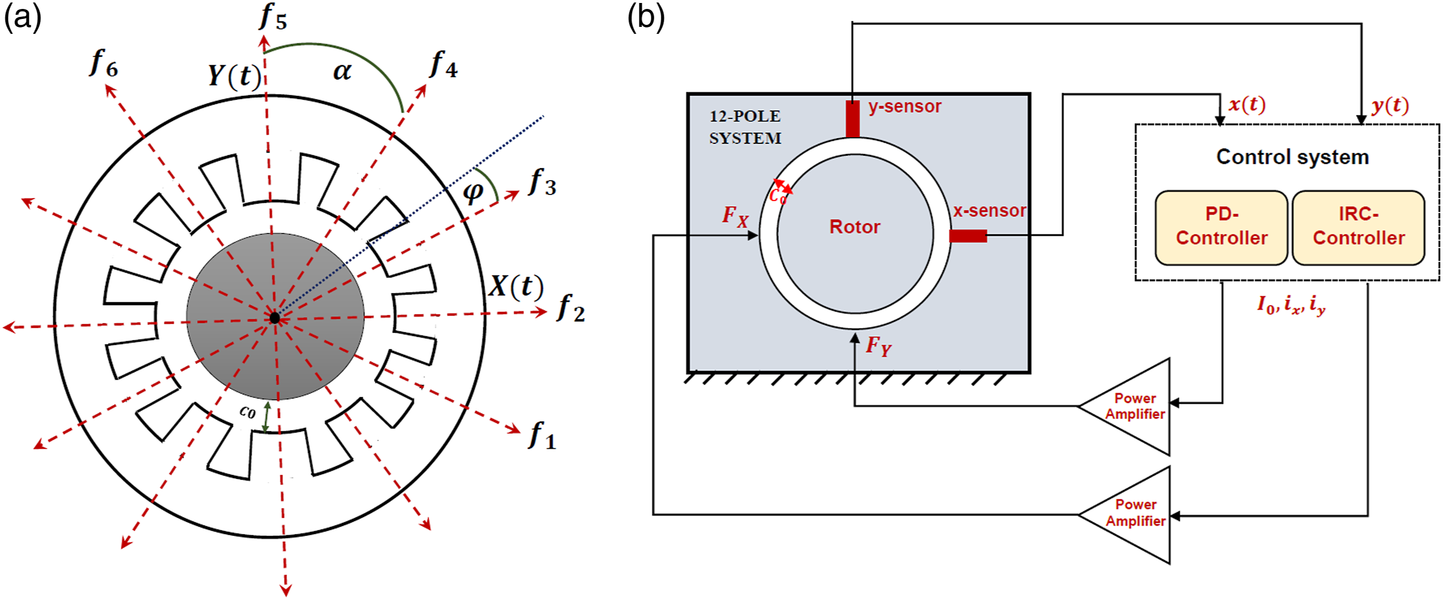
This section is dedicated to derive the mathematical model that governs the dynamics of the 12-pole system controlled by the IRC and PD controllers. It is supposed that the considered rotor performs a planner motion in the plane as illustrated in Figure 1(a). Accordingly, the equations of motion in and directions can be expressed as follows44,45
where denote the rotor mass, represents the rotor eccentricity, is the angular velocity, and and are the net attractive control forces that are applied in the and directions using the 12 electromagnetic poles as shown in Figure 1(b).
(a) 12-pole system schematic diagram and (b) closed-loop control system.
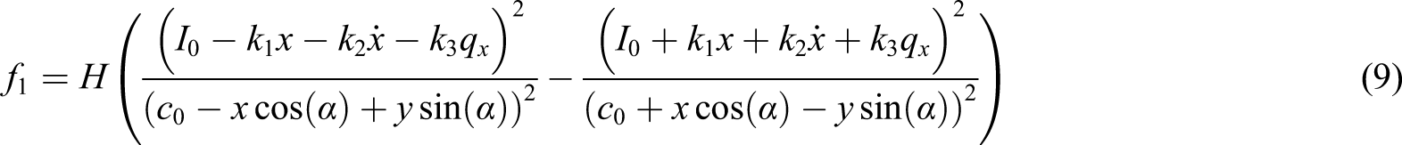
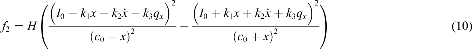
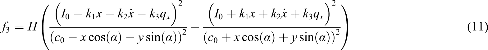
It is considered that each opposite two poles are designed to produce push-pull electromagnetic force to suspend the rotating shaft within the origin as shown in Figure 1(a) regardless of the external loads (i.e., the centrifugal force ). Accordingly, the push–pull control force of each pair of the opposite poles can be written such that45
where is constant (), is a constant permanentized electrical current, is the control current of the jth pole (It will be defined later according to the proposed control law), and denotes the air-gap size when the geometric center of the rotor coincides with the origin . is the instantaneous air-gap of the jth pole and its opposite one when the rotor system performs Cartesian displacements and . According to Figure 1(a), can be defined as follows
It is supposed that the control forces and are functions of the rotor horizontal displacement and the corresponding velocity , while the forces and are a function of the rotor vertical displacement and the corresponding velocity . Therefore, we can write
where denotes the control current in direction and is the control current in direction. These control currents are designed in this article to be generated via combined IRC and PD controllers. So, we can express the control currents ( and ) as follows
where and represent the position and velocity control gains, respectively, denotes the control signal gain of the IRC in direction, and is the control signal gain of the IRC direction. The IRC is a first-order linear dynamical system that is coupled to the targeted system linearly.29–36 Accordingly, the IRC dynamical model can be expressed as
where and are the IRC feedback signal gains, and and are the internal loop feedback gain. Substituting equations (4)–(6) into equation (3), yields
According to the geometry of Figure 1(a), The net attractive control forces and can be expressed as
Substituting equations (9)–(16) in equations (1) and (2), with introducing the dimensionless variables: with and omitting the asterisks for simplicity, we get the whole system model from equations (1), (2), (7), and (8) as follows
where, , , , , , , , , , ,
Based on the introduced dimensionless parameters before equations (17)–(20), we can deduce that and denote the dimensionless forms of the IRCs control gains ( and ). In addition, and represent the dimensionless forms of the IRCs feedback gains ( and ). Moreover, and are the dimensionless forms of the IRCs internal loop feedback gains ( and ). Also, and are the dimensionless forms of the proportional () and derivative () gains of the PD-controller. To explore the effects of the various controller gains (i.e., and ) on the oscillatory motion of the considered system, an analytical approximate solution for the derived dynamical system (i.e., equations (17)–(20)) is obtained using as given below.
Analytical investigation and autonomous amplitude-phase equations
Relying on the perturbation theory, a first-order approximate solution for the derived equations of motions (i.e., equations (17)–(20)) can be expressed as follows 38, 39
where is the perturbation parameter, , and . According to the time scales and , the derivatives and can be expressed as
To perform the solution procedure, the system parameters may be scaled such that
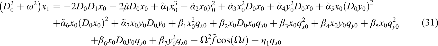
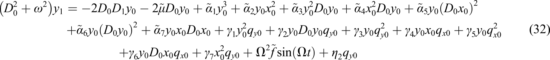
Inserting equations (21)–(26) into equations (17)–(20), and then equating the coefficients that have the same power of , yields O ()
Substituting equations (33) and (34) into the right-hand side of equations (29) and (30), and then solving the resulting equation, we have
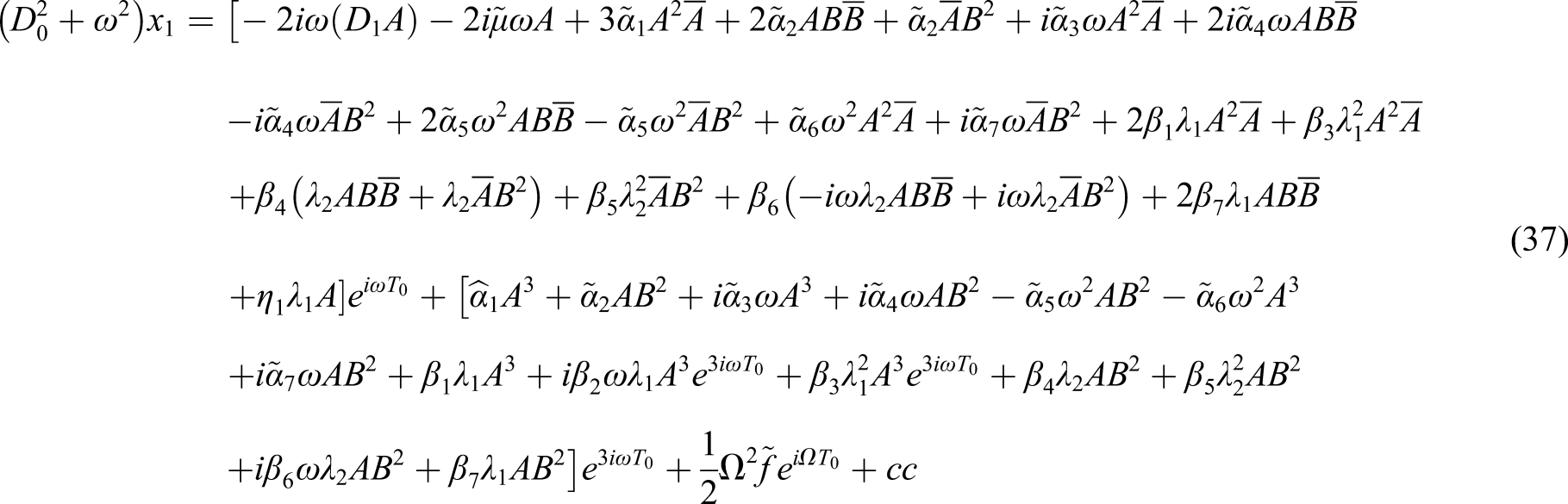
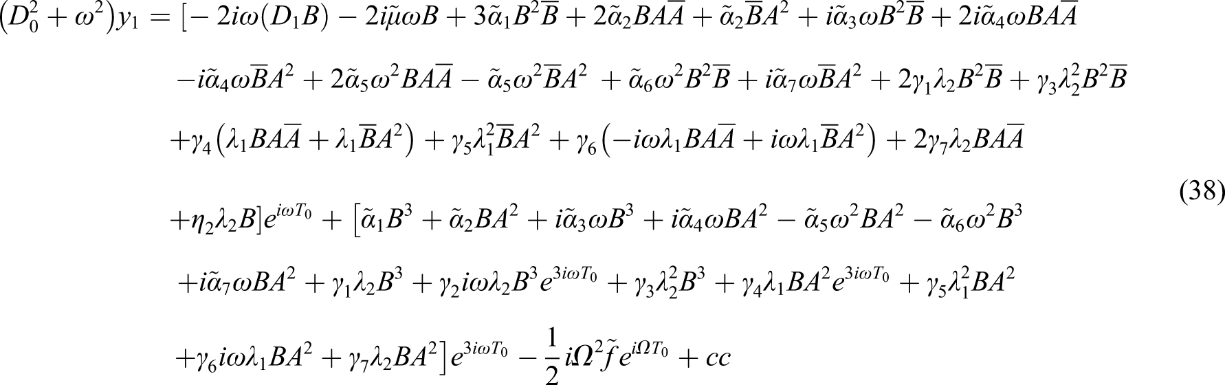
where , and the unknown functions , will be determined later. Now, inserting equations (33)–(36) into the right-hand side of equations (31) and (32) into equations (31) and (32), yields
where denotes the complex conjugate term. To investigate system oscillatory behavior at the primary resonance conditions (i.e., when ), it is convenient to present the detuning parameter to describe the closeness to as follows
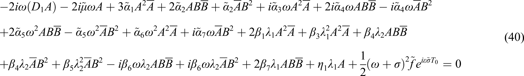
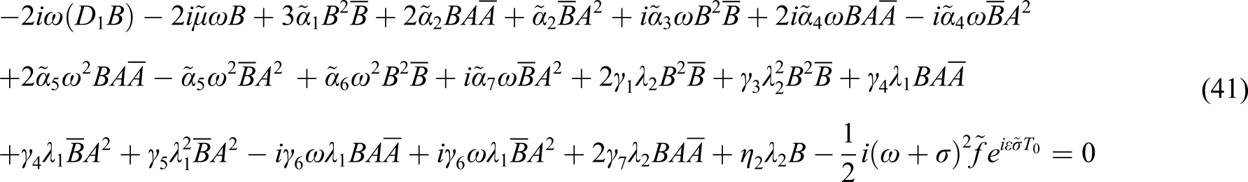
Inserting equation (39) into equations (37) and (38), we can extract the following secular terms38,39
To obtain the slow-flow modulating equations of the considered 12-pole system, we can express the unknown functions and in their polar form as38,39
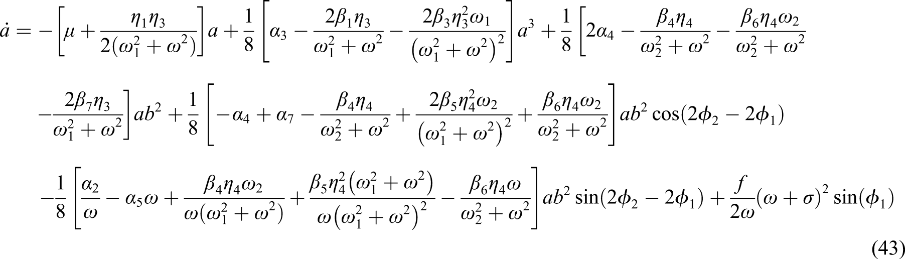
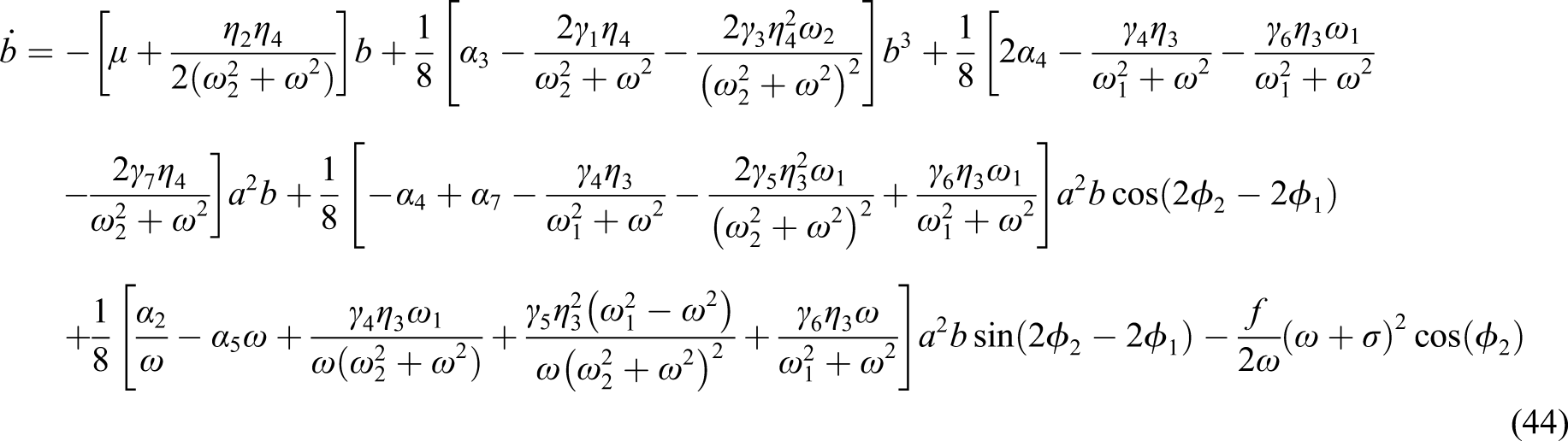
Inserting equation (42) into equations (40) and (41), with separating the real and imaginary parts, one can obtain the following nonlinear autonomous dynamical system
ϕ1= σt − θ1, ϕ2= σt − θ2 where Now, by inserting equations (42) and (33)–(36) into equations (21)–(24) taking into account equation (39), we can obtain the periodic solution of equations (17)–(20) as follows
It is clear from equations (47)–(50) that and are the vibration amplitudes of the 12-pole rotor in and directions, respectively, and and are the motion phase angles. The nonlinear autonomous system (43)–(46) governs the vibration amplitudes () and phase angles (). Accordingly, the steady-state amplitudes and phase angles of equations (17)–(20) can be obtained via setting into equations (43)–(46), to get the following nonlinear algebraic system of equations
By solving the above nonlinear algebraic system (i.e., ) in terms of one of the parameters and , we can establish the various bifurcation diagrams as given in the following section. In addition, the stability of the steady-state solution can be explored by applying the Hartman–Grobman theorem.46 This can be done via letting () be the solution of equations (51)–(54) and assuming that () is a variation about that solution. According to these assumptions, we can write
Substituting equations (55) and (56) into equations (43)–(46), expanding the resulting equations for the small deviations and keeping the linear terms only, yield
According to the Hartman–Grobman theorem46, the linear dynamical system (57) is equivalent to the nonlinear system (43)–(46). Therefore, the stability of the solution of equations (51)–(54) can be investigated by examining the linear system’s eigenvalues given by equation (57).
Bifurcation diagrams and the performance of the integral resonant controller
This section investigates the effects of various controller parameters on rotor steady-state vibration amplitudes () and phase angles (). Solving the derived nonlinear algebraic system equations (51)–(54) (numerically using the Newton–Raphson algorithm47), one can obtain the response curves as shown in Figure 2, Figure 3, Figure 4, etc. The solution’s stability of equations (51)–(54) can be explored by investigating the eigenvalues of the linear system given by equation (57), where the stable solution is plotted as a solid line and the unstable one is illustrated as a dotted line. In addition, to confirm that the derived nonlinear algebraic system (i.e. equations (51)–(54)) describes with high accuracy the steady-state vibration amplitudes of the nonlinear system governed by equations (17)–(20), the steady-state oscillation amplitudes of equations (17)–(20) are obtained numerically using Rung–Kutta algorithm. The numerical solution of equations (17)–(20) is plotted as a small circle when the bifurcation parameter is being swept forward and as a big dot when it is being swept backward. The following parameter values are used to simulate the considered system. Unless otherwise stated, the analytical and numerical findings were obtained by using the following values for the system parameters: , and [15].
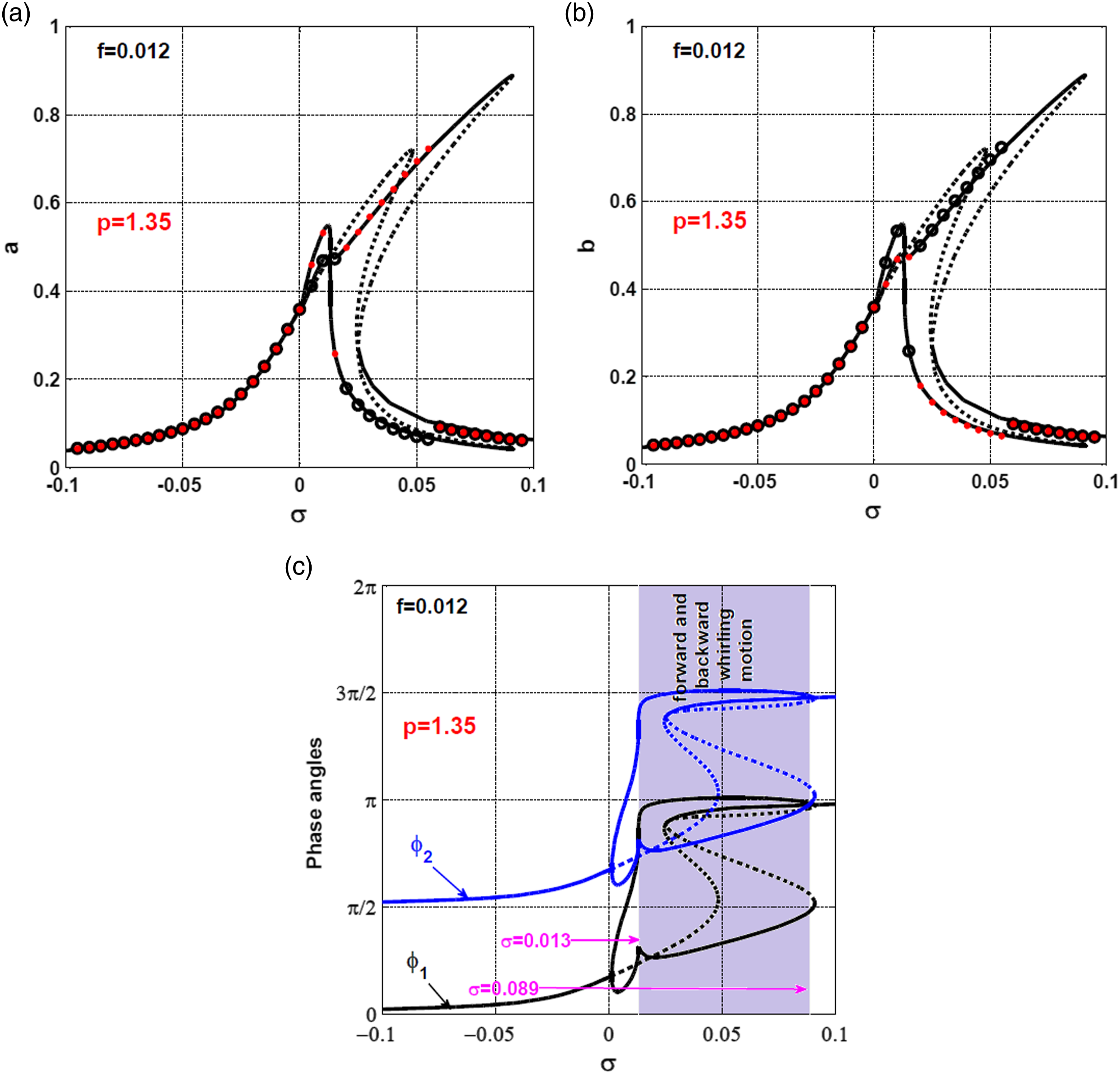
12-pole system response curve when : (a) vibration amplitude in direction, (b) vibration amplitude in direction, (c) the steady-state phase angles at , and (d) the steady-state phase angles at .
12-pole system response curve at and : (a) vibration amplitude in direction, (b) vibration amplitude in direction, and (c) steady-state phase angles.
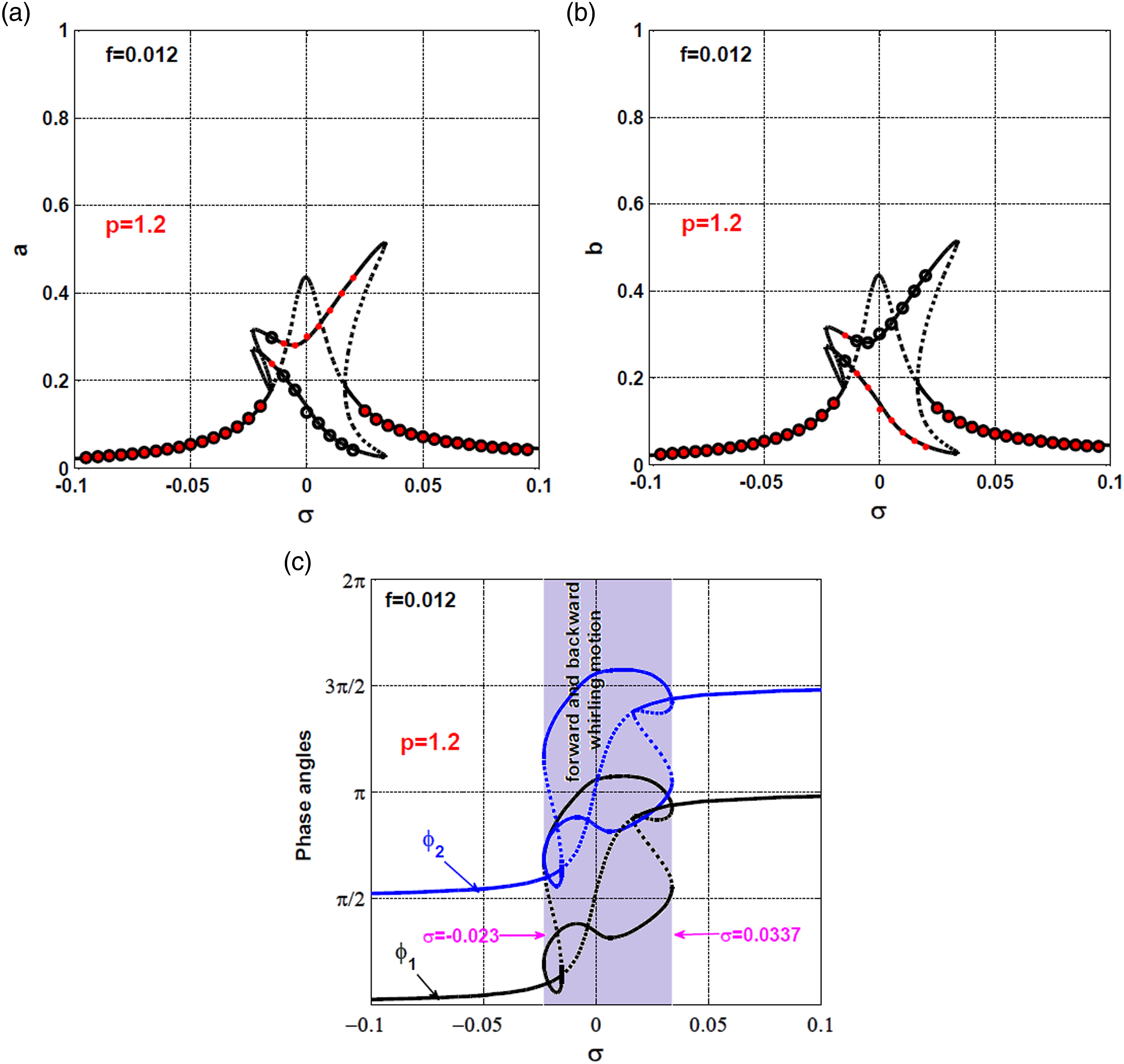
12-pole system response curve at and : (a) vibration amplitude in direction, (b) vibration amplitude in direction, and (c) steady-state phase angles.
12-pole rotor system dynamics without integral resonant controller
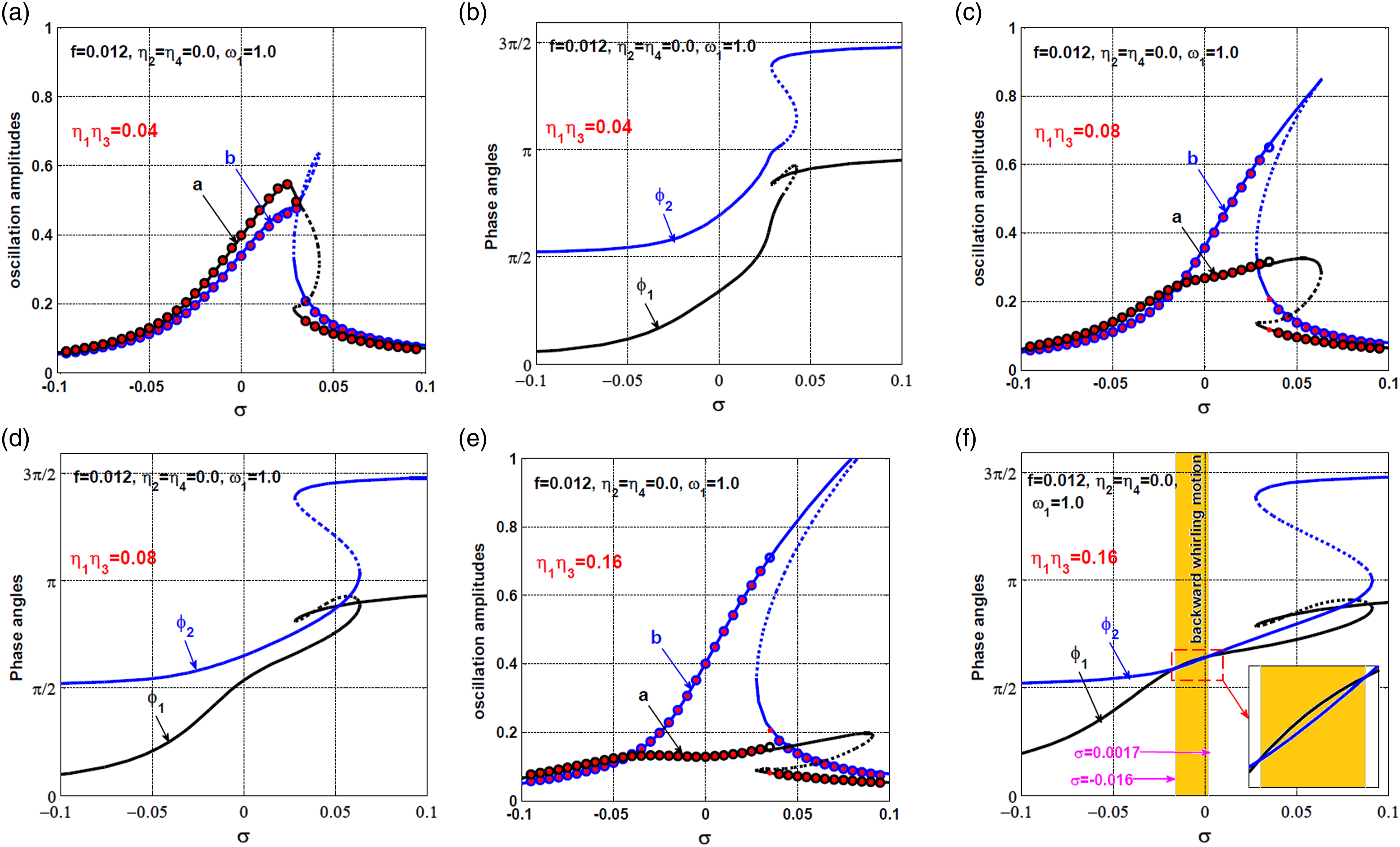
The dynamical behavior of the 12-pole system without IRC control is discussed within this subsection via solving equations (51)–(54) when . Before proceeding further it should be remembered that the dimensionless parameters of the rotor system and PD-controller are defined before equations (17) so that and . Accordingly, one can deduce that represents the dimensionless form of the actual eccentricity , is the normalized form of the actual angular velocity , denotes the dimensionless form of the actual proportional gain , and is the dimensionless form of the actual derivative gain . In addition, the parameter represents the closeness of to the system natural frequency as given in equation (39) (i.e., ). Therefore, the parameter is employed as a bifurcation parameter to describe the system oscillation amplitudes () and phase angles (, ) of the rotor system at the primary resonance case (i.e., ) as shown in Figures 2–4 and so on.
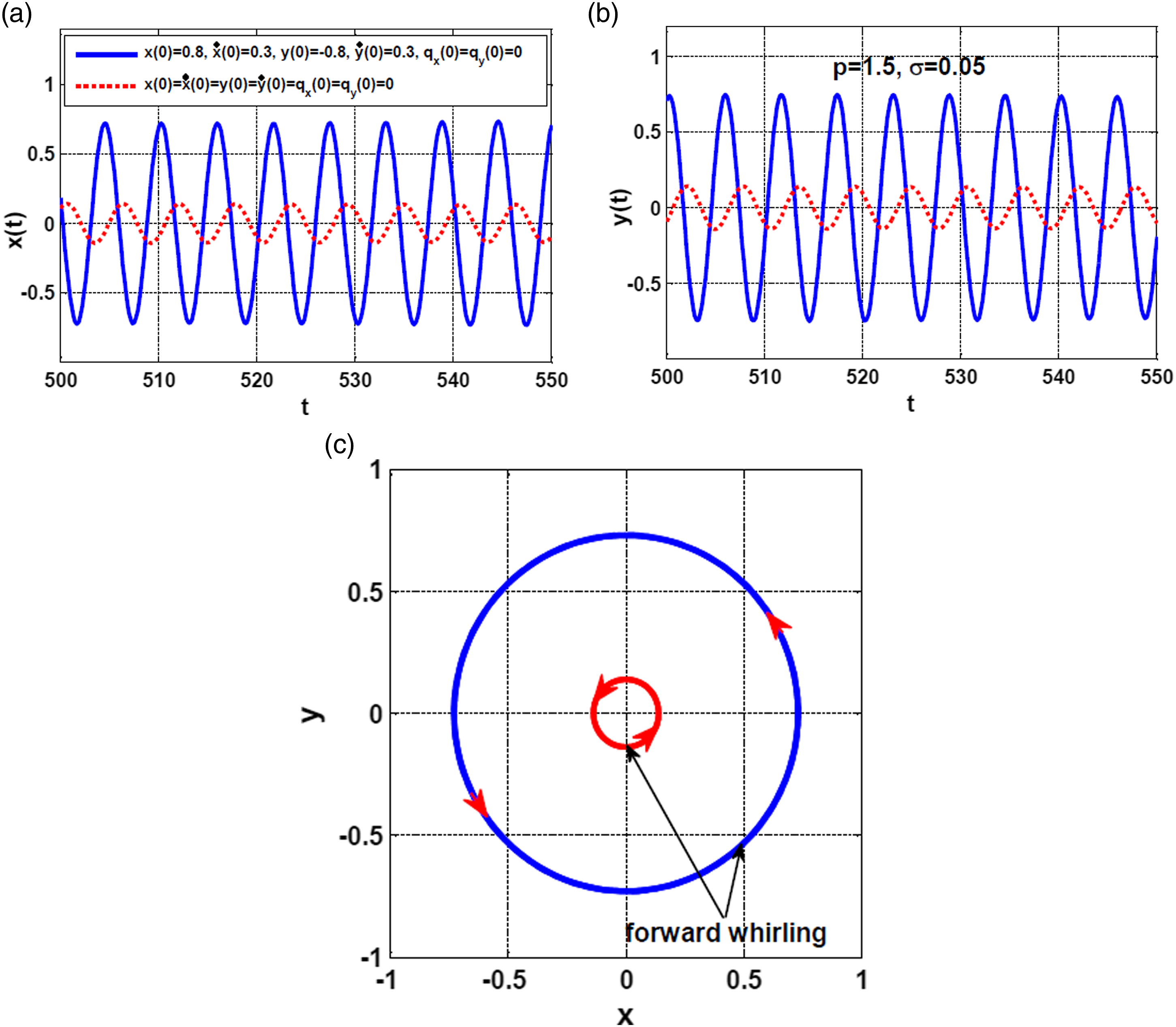
Figure (2) illustrates the 12-pole system oscillation amplitudes and phase angles at different values of the eccentricity when and . Figures 2(a) and (b) show that the 12-pole system vibrations when and . The figures depict that system lateral vibration amplitudes are a monotonic growing function of , where the nonlinearities dominate the system motion when and . Figures 2(a) and (b) depict that the rotor system behaves as a hardening Duffing oscillator at large disc electricity with symmetric motion in and directions. Based on equations (47) and (48), the rotor system can execute forward whirling motion (i.e., whirling counterclockwise) as long as , while the system exhibits backward whirling (i.e., whirling clockwise) if . In addition, the system oscillates along a straight line with a slope if . Therefore, one can determine the whirling direction of the rotor system by plotting the phase angles () against the targeted bifurcation parameter. Figures 2(c) and (d) illustrate the evolution of the system phase angles against the detuning parameter when and , respectively. Figures 2(c) and (d) show that the phase difference , which demonstrated that the rotor system performs circular forward whirling motion when and regardless of the magnitude of the eccentricity.
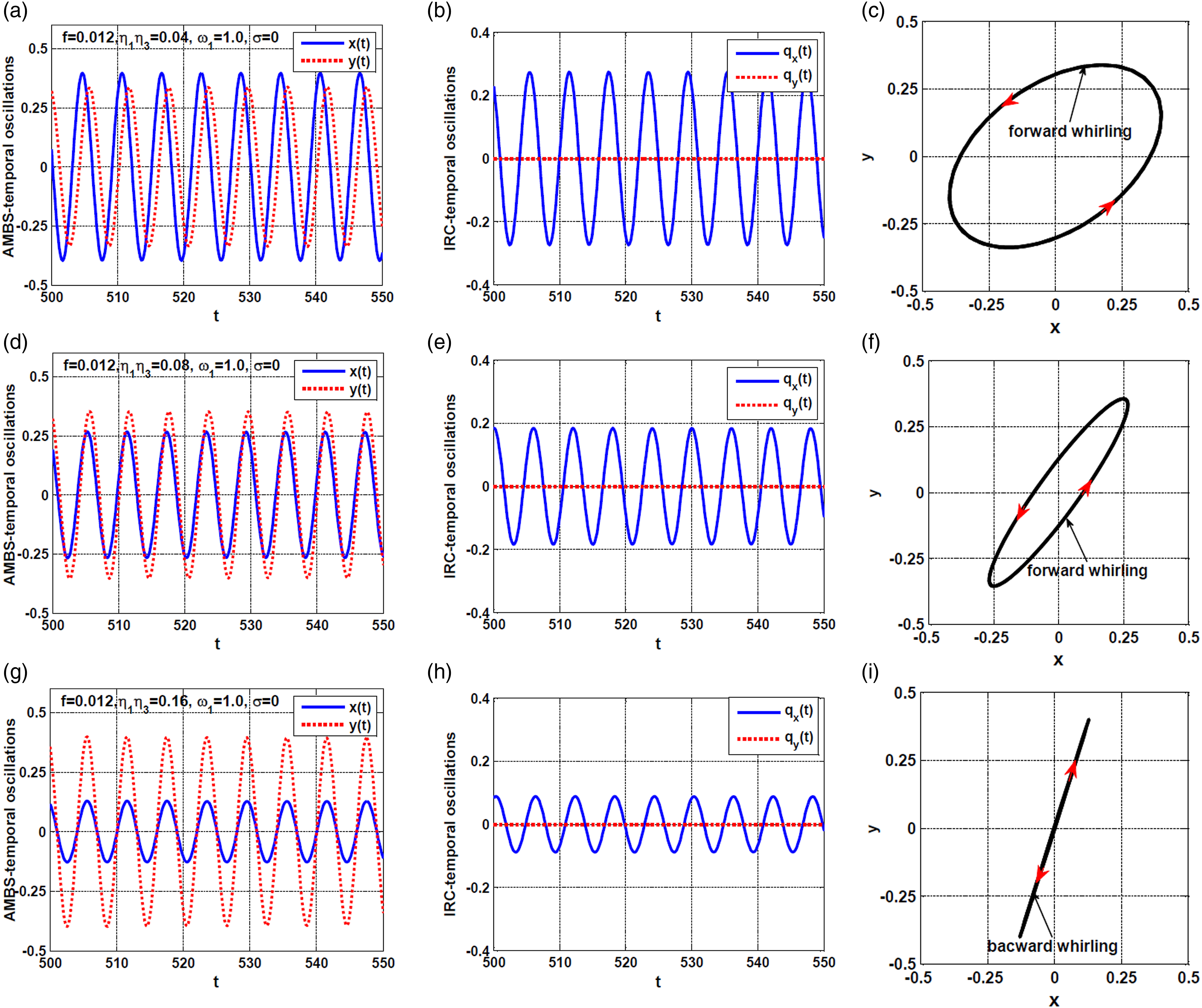
To confirm the precision of the findings shown in Figure 2, the rotor system’s steady-state temporal oscillations and whirling motion have been numerically simulated as shown in Figure 5 via solving the system dynamical model given by equations (17)–(20) using ODE45 MATLAB function according to Figure 2 when (i.e., when and ). It is clear from Figures 2(a) and (b) that the system has two stable solutions at and . Therefore, equations (17)–(20) have been solved numerically using two trial initial conditions (i.e. and ). By examining Figure 5, one can confirm that the rotor may vibrate by one of two stable periodic solutions according to the initial position. In addition, the system performs forward circular whirling motion because and have the same magnitude as well as the phase difference as is clear in Figure 2(d).
The steady-state temporal vibrations of the rotor system according to Figure 2 when at the initials and : (a, b) the vibration in and directions, (c) the whirling motions.
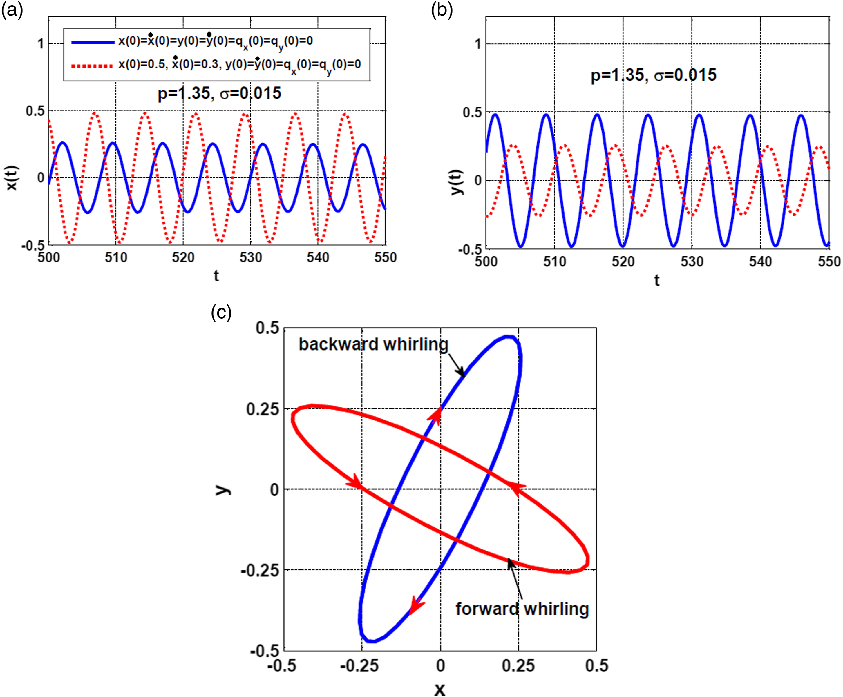
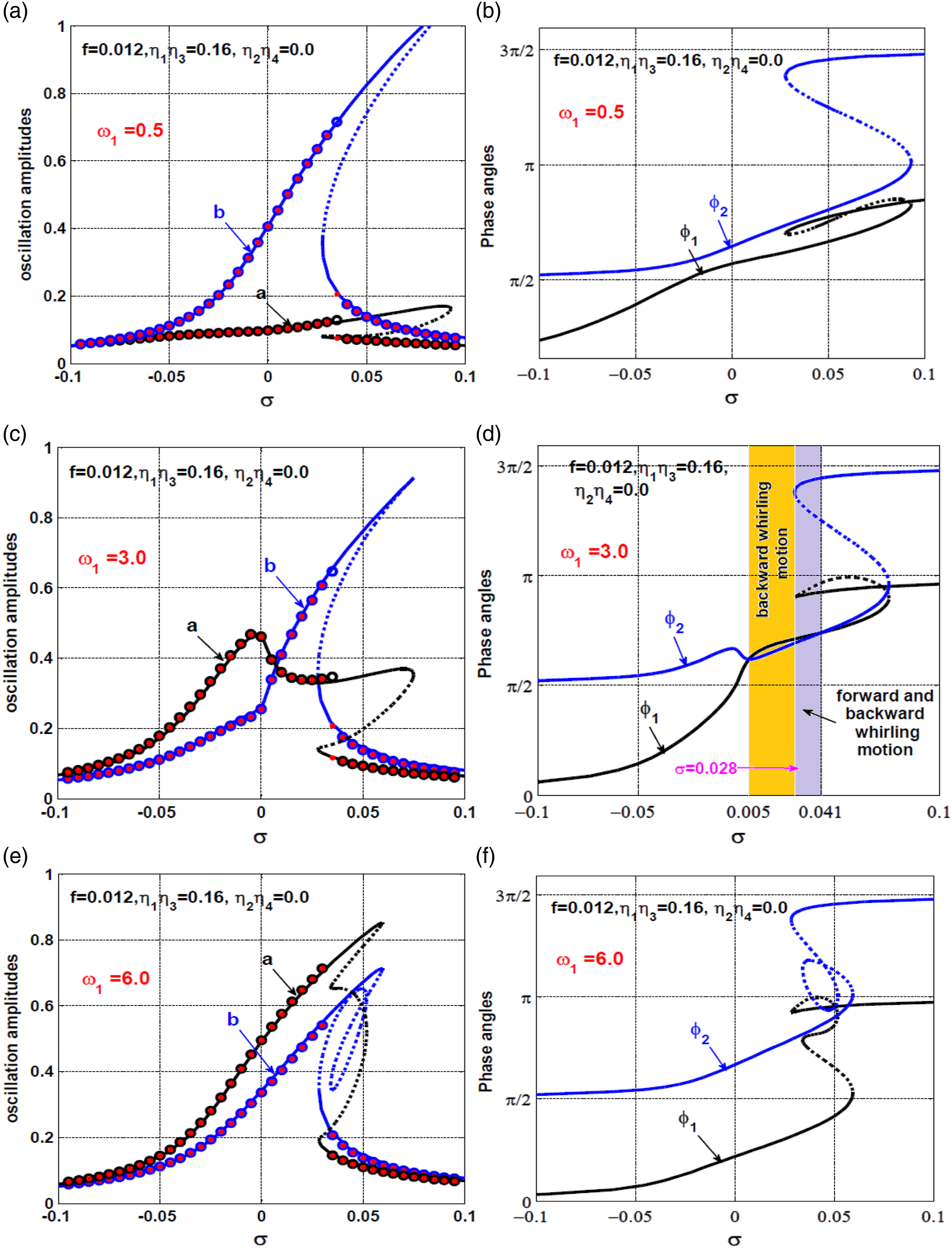
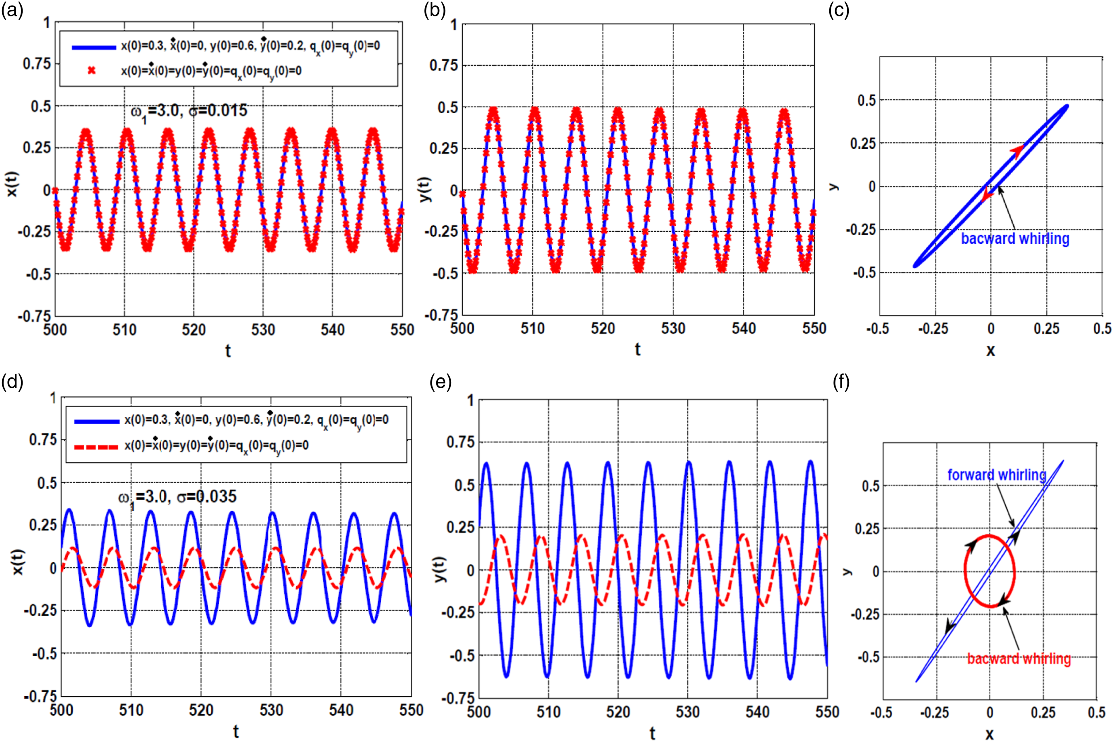
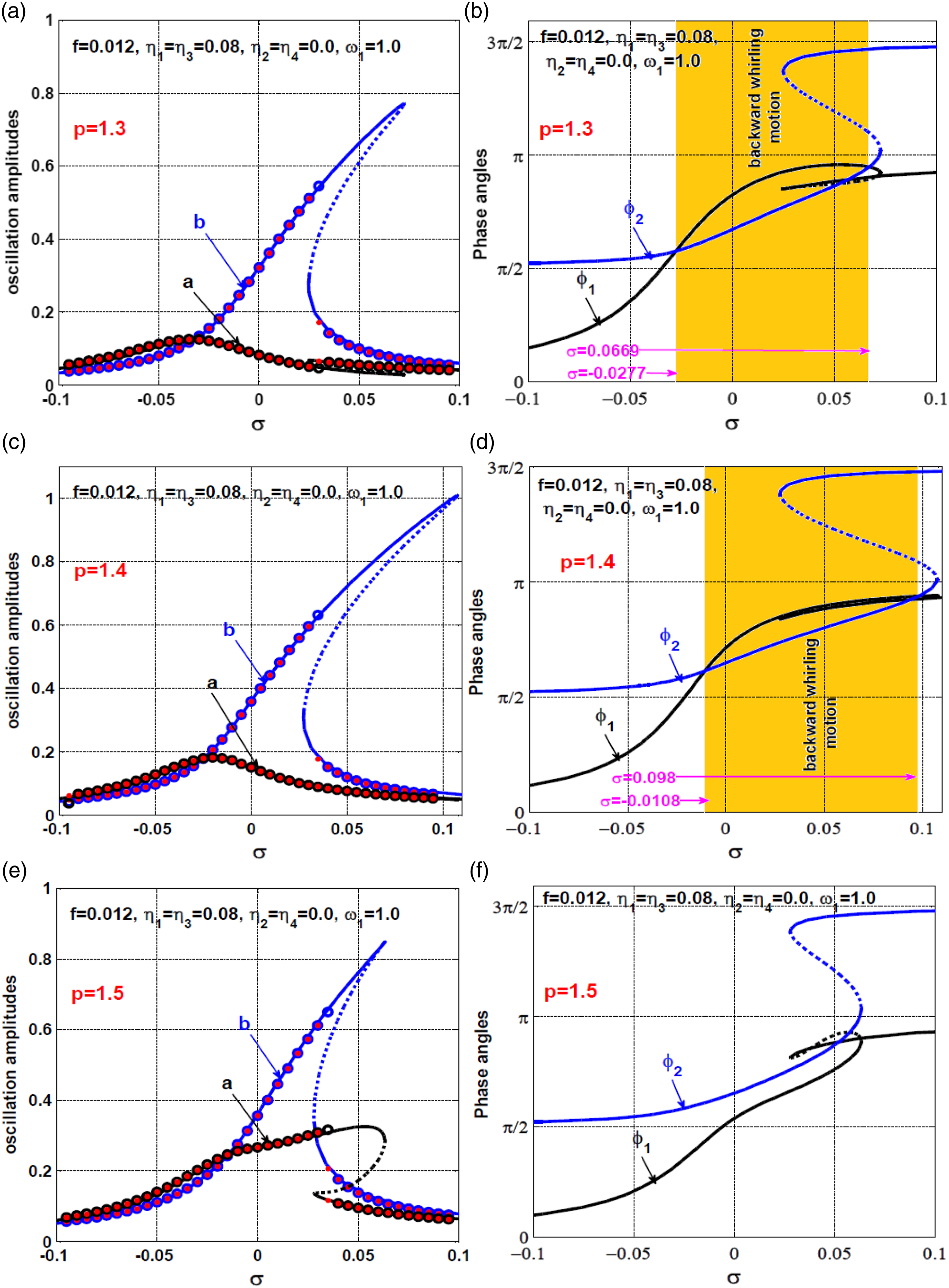
The effect of decreasing the proportional gain from as in Figure 2 to or is illustrated in Figures 3 and 4. The figures show the complex static bifurcation behaviors when decreasing the proportional gain beyond ., where the system may respond with mono-stale, bi-stable, and tri-stable solutions depending on the angular velocity . In addition, Figures 3(c) and 4(c) show that the system can whirl backward or forward according to the value of the initial conditions at the same spinning speed. The rotor temporal oscillations and the whirling orbit according to Figure 3 at have been illustrated in Figure 6 via solving equations (17)–(20) numerically utilizing the two initials and , where the figure confirms the elliptic forward or backward whirling motion of the system.
The steady-state temporal vibrations of the rotor system according to Figure 4 when five at the initial conditions and : (a, b) the vibration in and directions, (c) the whirling motions.
Based on Figure 3, Figure 4, and Figure 6, one can demonstrate that the dynamical characteristics of the 12-pole system are particularly sensitive to the proportional gain, where for the large values (i.e., ), the system responds with simple bifurcation behaviors like the hardening spring Duffing oscillator but with strong oscillation amplitudes. On the other hand, at the small values of the proportional gain (i.e. ), the system responds with small oscillation amplitudes, but it may exhibit complex bifurcation behaviors. Accordingly, the IRC has been introduced along with the PD-controller to improve the dynamical characteristics of the considered system as discussed in The 12-pole rotor dynamics with asymmetric IRC controller and The 12-pole rotor dynamics with symmetric IRC controller.
Before going any further, it’s crucial to keep in mind that the IRC control parameters have been defined in their dimensionless form before equation (17) such that and . According to these definitions and based on equations (6)–(8), one can simply deduce that and represent the dimensionless forms of the control signal gains ( and ) of the IRCs that are connected to the horizontal and vertical oscillation modes, respectively. In addition, and are the dimensionless forms of the feedback signal gains ( and ) of the IRCs. Moreover, and denote the dimensionless forms of the internal feedback signal gains ( and ) of the integral resonant controllers. Secondly, it is clear from the derived autonomous dynamical system given by equations (43)–(46) that the integration of the integral resonant controllers to the 12-pole system has modified the linear damping (i.e., ) to the equivalent damping (in the horizontal direction) and (in the vertical direction). In addition, the detuning parameter has been modified to the equivalent detuning parameters (in the horizontal direction) and (in the vertical direction). Accordingly, is proportional to the multiplication of both control and feedback gains (i.e., ) of the IRC that is connected to the horizontal oscillation mode only, and inversely proportional to the square of as well as the square of the system’s natural frequency (). In addition, is proportional to the multiplication of both control and feedback gains () of the IRC that is connected to the vertical oscillation mode, and inversely proportional to the square of both and . Therefore, the product of the control and feedback gains and as well as the internal loop feedback gain can be utilized to reshape the rotor dynamics in the horizontal direction via adjusting the values of and , while the product of the control and feedback gains and as well as the internal loop feedback gain can be utilized to control the rotor dynamics in the vertical direction via controlling the values of and .
Based on the above explanations, the influence of the different control parameters (i.e., and ) on the rotor dynamics has been investigated in two-stage of analyses. In the first stage, the rotor dynamics have been explored when activating the IRC controller that is connected to the direction only when turning off the other controller (i.e., ) in The 12-pole rotor dynamics with asymmetric IRC controller. In the second stage, the two controllers are treated as one controller by letting and as discussed in The 12-pole rotor dynamics with symmetric IRC controller.
12-pole rotor dynamics with asymmetric IRC controller
The 12-pole rotor dynamics have been investigated within this section when activating the IRC that is coupled to the horizontal direction with turning off the controller in the vertical direction (i.e., ). Figure 7 shows the response curve of the 12-pole rotor system at three different values of (i.e., at ) when . It is clear from Figures 7(a) and (c), and (e) that the maximum oscillation amplitude of the rotor system in the horizontal direction is when , when , and when . Accordingly, one can deduce that the system oscillation amplitude in the horizontal direction is a monotonic decreasing function of the product of both the control and feedback signal gains , which agrees with the mathematical explanation given above, where increasing of , increases the system equivalent damping coefficient in the horizontal direction () without affecting the equivalent damping in the vertical direction . Despite increasing of decreases the system oscillation amplitude in direction, it cannot eliminate the motion bifurcation, where the bistable solution region and nonlinearities still dominate the system response due to the natural nonlinear coupling between the horizontal and vertical oscillation modes. Figures 7(b) and (d), and (f) also show that activating one of the controllers can change the whirling direction of the rotor system either forward or backward depending on the spinning speed ( and the values of .
12-pole system response curve at and : (a, b) , (c, d) , and (e, f)
Numerical simulation for the temporal oscillations and whirling motion of the system according to Figure 7 at , and is illustrated in Figure 8 via solving equations (17)–(20) using ODE45. Figures 8(a) to (c) show the temporal oscillation and the whirling motion of the system and controller at , Figures 8(d) to (f) illustrate the lateral vibrations and the corresponding whirling motion of the system and controller when , and Figures 8(g) to (i) depict the temporal vibration and the corresponding whirling motion of the system and controller when and . Comparing Figures 8(a), (d), and (g), it is clear the temporal oscillations of the 12-pole rotor system decrease as increases. In addition, Figures 8(c), (f), and (i) confirm that the system can perform elliptic forward or backward whirling motion depending on the magnitude of when fixing .
The steady-state temporal oscillations of the rotor system and IRC according to Figure 7 when : (a, b, c) , (d, e, f) , and (g, h, i) .
The effects of the internal feedback gain on the oscillation amplitudes of the considered system have been illustrated in Figure 9 when Figures 9(a) and (b) shows the system oscillation amplitudes and phase angles versus the angular velocity when , while the rotor system lateral oscillations and the phase angles are illustrated in Figures 9(c) and (d) when . In addition, the system’s steady-state lateral vibration and the phase angles have been shown in Figures 9(e) and (f) when . Comparing Figures 9(a) and (c), and (e), one can deduce that the increase in the internal feedback gain from to then to , increases the rotor oscillation amplitude and shifts the whole response curve to the left. In addition, Figures 9(b) and (f) illustrate that the rotor can exhibit forward whirling only regardless of the initial conditions and the system angular velocity. However, Figure 9(d) shows that the system can perform one of three whirling modes according to the rotor angular velocity, which are: (1) forward whirling only, (2) backward whirling only, and (3) forward or backward whirling.
12-pole system response curve at and : (a, b) , (c, d) , and (e, f)
Numerical simulations for the system’s original equations (17)–(20) according to Figures 9(c) and (d) when and have been shown in Figure 10. Figures 9(c) and (d) illustrate that the rotor system has a monostable solution only where at , while at , the system has bi-stable solutions where with one of these solutions and with the other solution. Accordingly, it is expected that the system may whirl backward with a unique solution regardless of the intimal conditions when . On the other hand, it is expected that the system may whirl forward or backward at depending on the initial conditions. Therefore, the two initials and are have been used to solve equations (17)–(20) numerically when and as shown in Figures 10(a) to (f), respectively. One can note from Figures 10(a) to (c) that the system executes backward whirling motion regardless of the initial conditions, while Figures 10(d) to (f) show that the 12-pole system executes either backward or forward whirling according to the initial position of the rotor.
The temporal oscillations of the 12-pole rotor and IRC according to Figures 9(c) and (d) when and at the initial conditions and : (a, b, c) , and (d, e, f) .
The influence of the proportional gain on the control performance of the IRC has been investigated as shown in Figure 11, where the response curve for both the vibrations amplitudes and the phase angles are obtained when and . By examining Figures 11(a) and (c) and (e), one can find that the increase of the gain increases the system oscillation amplitude in direction.
12-pole system response curve at , and : (a, b) , (c, d) , and (e, f)
Based on Figures 9 and 11, it is clear that the rotor steady-state lateral oscillation in the horizontal direction (i.e., ) is a monotonic growing function of both the internal feedback gain () and the proportional gain . This mechanism can be explained according to the introduced definition in for the equivalent damping coefficient and . First, remember that the system’s natural frequency is a monotonic growing function of the proportional gain , where . Therefore, increasing the system’s natural frequency (via increasing ) or/and the internal feedback gain , decreases the system equivalent damping coefficient , which ultimately increases the oscillation amplitude in direction.
The bifurcation behaviors of the 12-pole system have been explored in Figure (12) utilizing as the bifurcation parameter at two different values of when . Figures 12(a) and (c) illustrate that the rotor exhibits stable periodic oscillations as long as . However, the system exhibits whirl backward or forward depending on the magnitude of both and . Figures 12(a) and (b) illustrate that the system vibrates periodically with forward whirling motion along the eccentricity axis except for the interval (), at which the rotor may execute backward whirling. Also, Figures 12(c) and (d) illustrate that the rotor system performs backward whirling as long as , otherwise, the system executes forward whirling.
12-pole system response curve and : (a, b) , and (c, d)
According to Figures 7–9, Figures 11 and 12, it is noticeable that activating one of the applied integral resonant controllers with turning off the other is resulting in the breakdown of the bifurcation symmetry of the considered system, which ultimately leads to different nonlinear phenomena such as (1) the appearance of the localized and nonlocalized oscillation and (2) the elliptic forward or/and backward whirling. However, the rotor system cannot lose its stability due to the asymmetry caused by the activation of one of the controllers only. Finally, it is important to note that if the values of the parameters and have been interchanged with the parameters and , respectively, one can obtain the same bifurcation diagrams that are given in Figures 7–9, Figures 11 and 12, but the bifurcation behaviors in and directions will be interchanged.
12-pole rotor dynamics with symmetric IRC controller
The influence of the symmetric IRC on the bifurcation behaviors of the considered rotor system is explored within this section. The coupled integral resonant controllers are considered as one controller via letting the control feedback gains , the feedback gains , and the internal feedback gain . According to equations (43)–(46), one can note that the coupling of the symmetric IRC to the 12-pole system modifies the system damping to the equivalent coefficients .
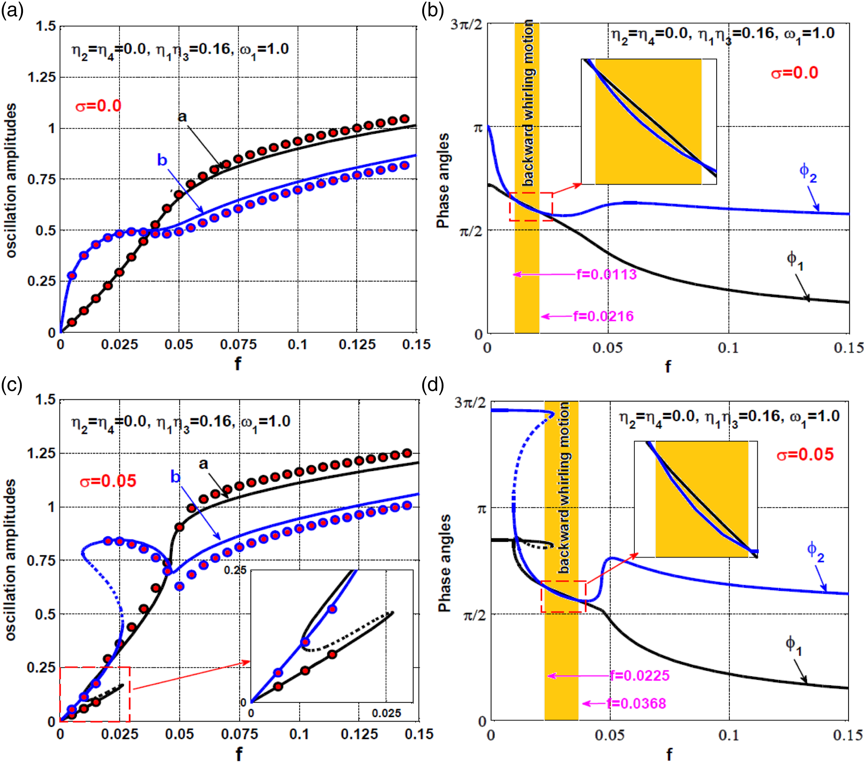
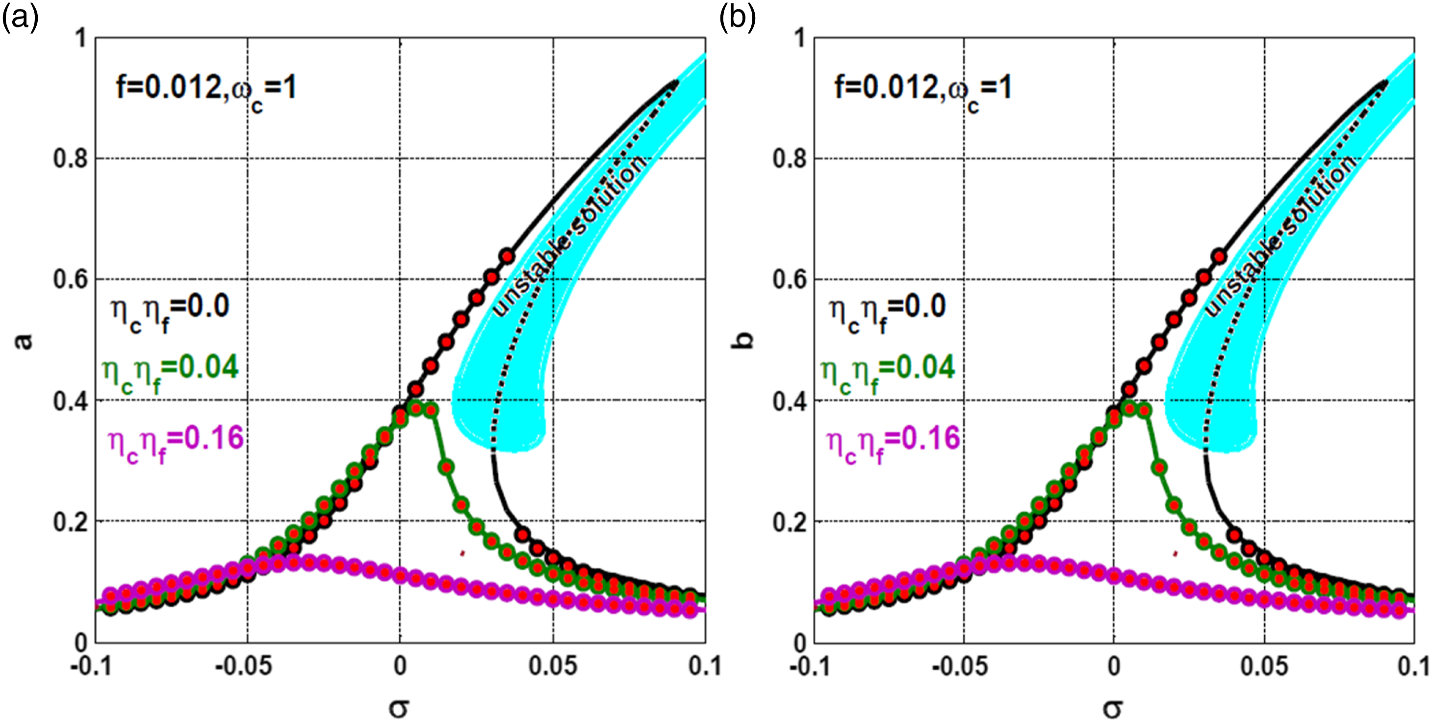
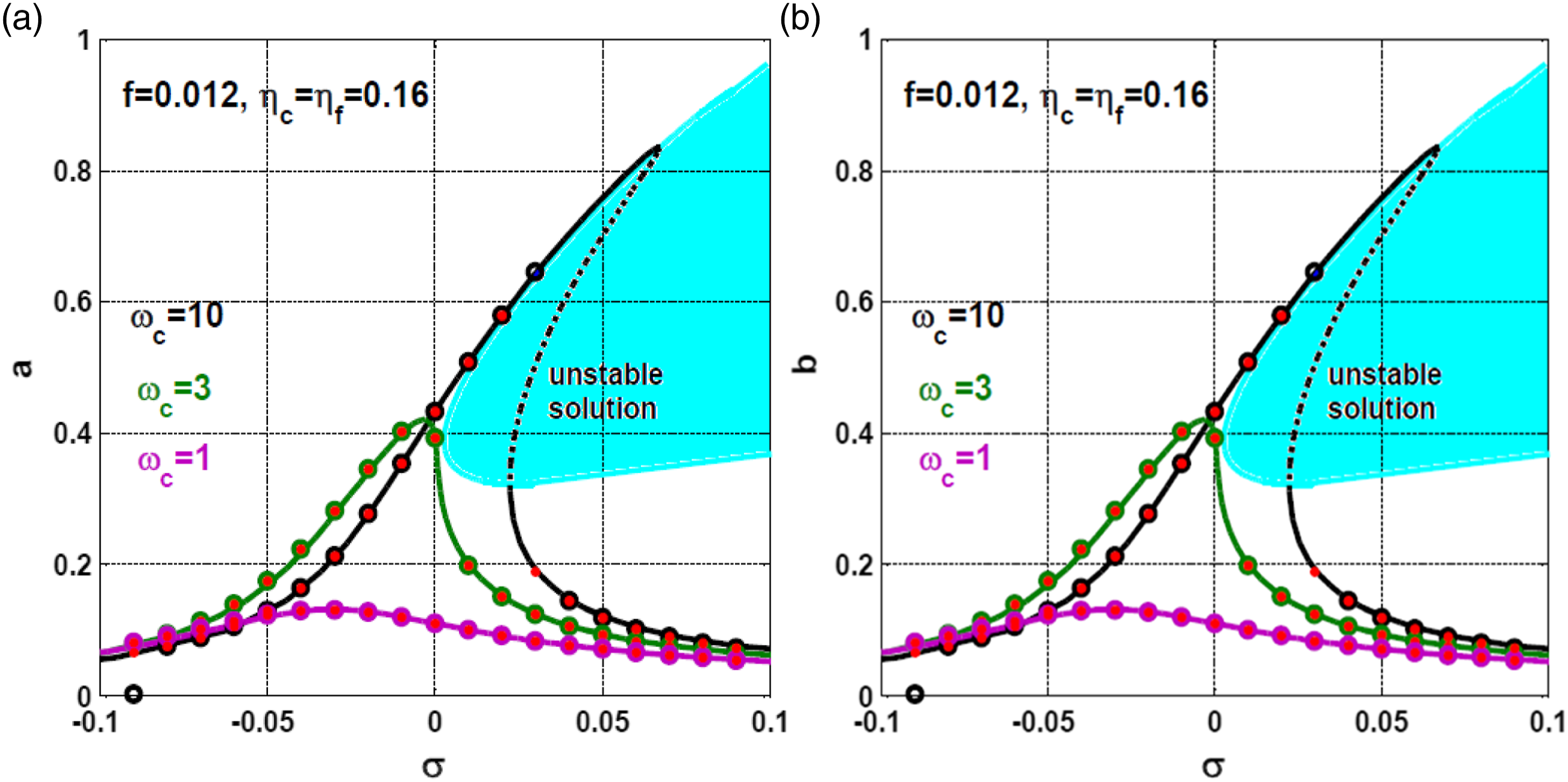
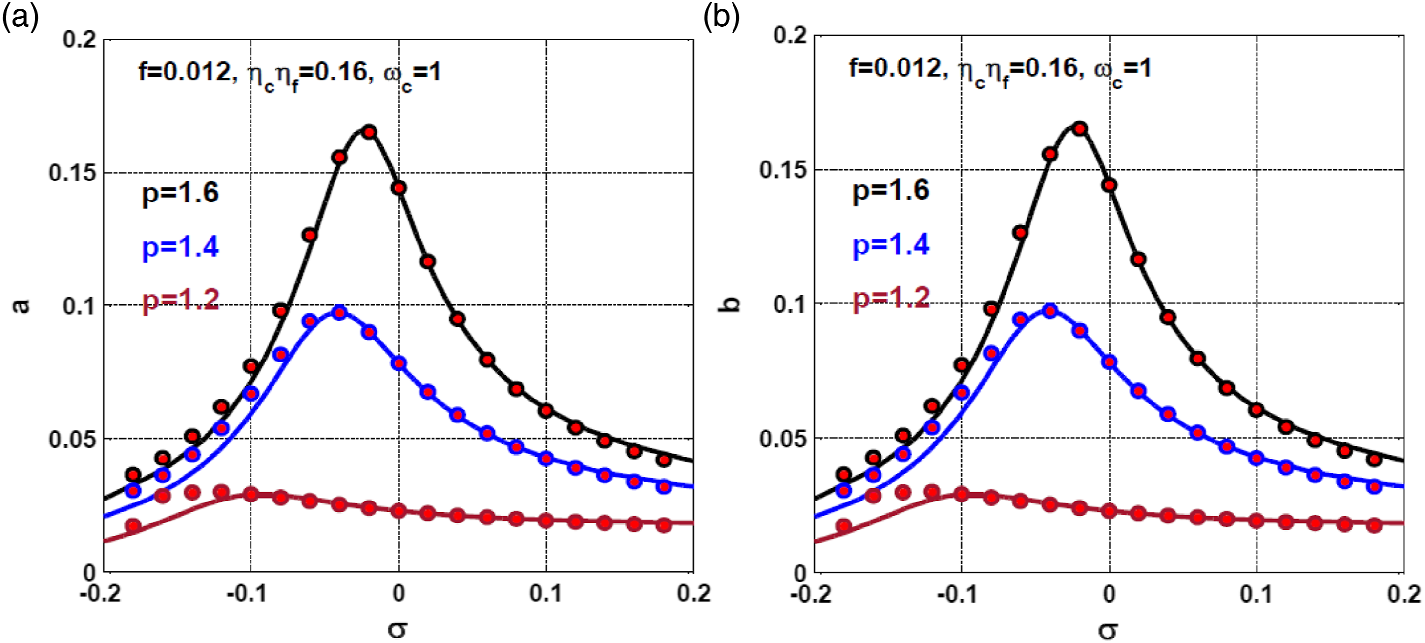
Based on the above assumption, the effects of the IRC parameters ( and ) on the rotor system dynamics are explored through Figure 13 illustrates the system response curve at various values of (i.e., when and ). The figure depicts that the 12-pole system lateral oscillation () are decreasing functions of . In addition, the figure shows the symmetric bifurcation behaviors in both the and directions. Moreover, the figure shows that increasing the gain to can eliminate the system vibration close to zero. The influence of increasing the internal feedback gain on the rotor lateral vibration is shown in Figure 14. The figure shows the lateral amplitudes ( and ) at and when and . The figure confirms that the 12-pole system behaves like the linear systems at and , but the nonlinearities may dominate the response when has increased to . Based on Figures 13 and 14, one can deduce that the oscillation amplitudes of the rotor are decreasing functions of the gain , and monotonic growing function of the internal feedback gain . It is worth mentioning that the deuced results from Figures 13 and 14 agree with the introduced definition of the new damping coefficient , where proportional to , and inversely proportional to . Accordingly, increasing and/or decreasing , increases the equivalent linear damping of the rotor system, which ultimately decreases the system lateral vibration in both and directions.
12-pole system response curve at and when and and : (a) vibration amplitude in direction, and (b) vibration amplitude in direction.
12-pole system response curve at and when and : (a) vibration amplitude in direction, and (b) vibration amplitude in direction.
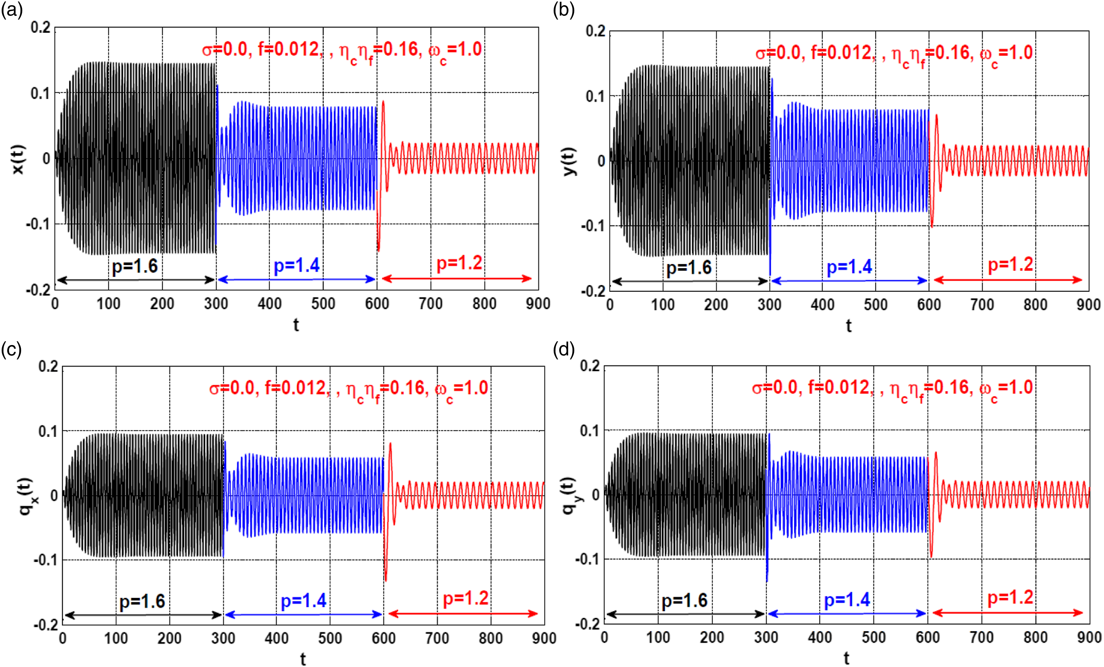
The control efficiency of the symmetric IRC in reducing the undesired vibrations of the 12-pole system is investigated when and as shown in Figure 15. By examining Figure 15, one can demonstrate that the increase of , increases the vibration amplitudes in both and directions. The main cause that made the oscillation amplitudes increase with increasing the proportional gain can be explained simply with the help of equivalent damping definition . It is clear that is inversely proportional to , where . Therefore, increasing the proportional gain decreases the system equivalent damping coefficient, which in turn increases the lateral vibration amplitudes. Figure 16 depicts the time-responses of both the 12-poles system and the coupled IRCs according to Figure 15 at (i.e., when , , ) when decreasing the proportional gain from to at , and then decreasing again from to at . One can note from the figure that the system oscillation amplitudes decrease with the decreasing proportional gain which agrees exactly with Figure 15 at . In addition, the figure illustrates the short transient time that the rotor takes to reach its steady state.
12-pole system response curve at and when and : (a) vibration amplitude in direction, and (b) vibration amplitude in direction.
The temporal vibrations of the rotor system and IRC according to Figure 15 when regardless of the initial conditions when and : (a, b) the rotor temporal oscillations in and directions, and (c, d) the temporal oscillations of the coupled integral resonant controllers.
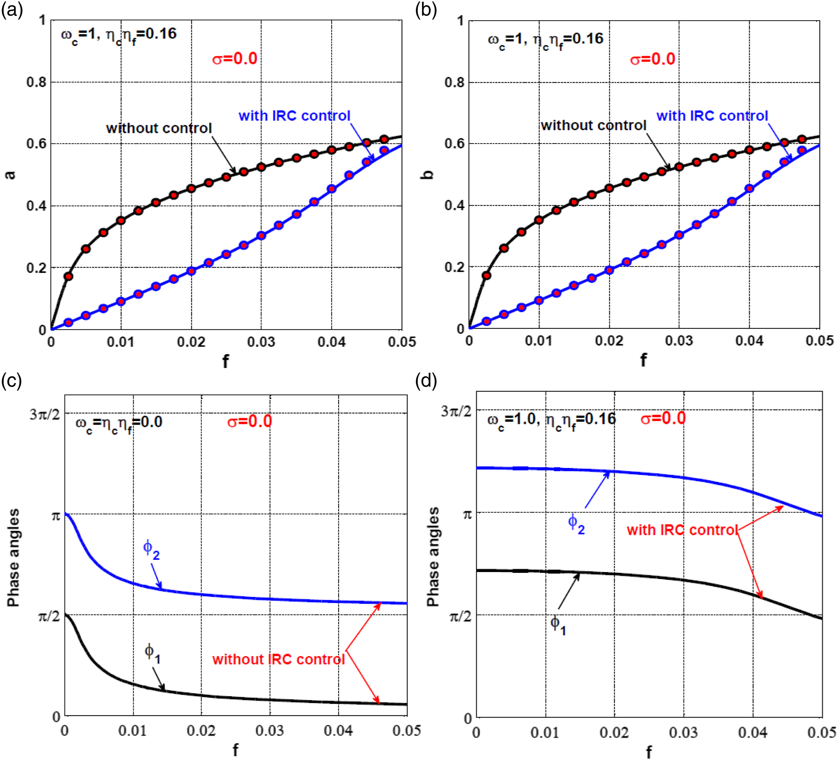
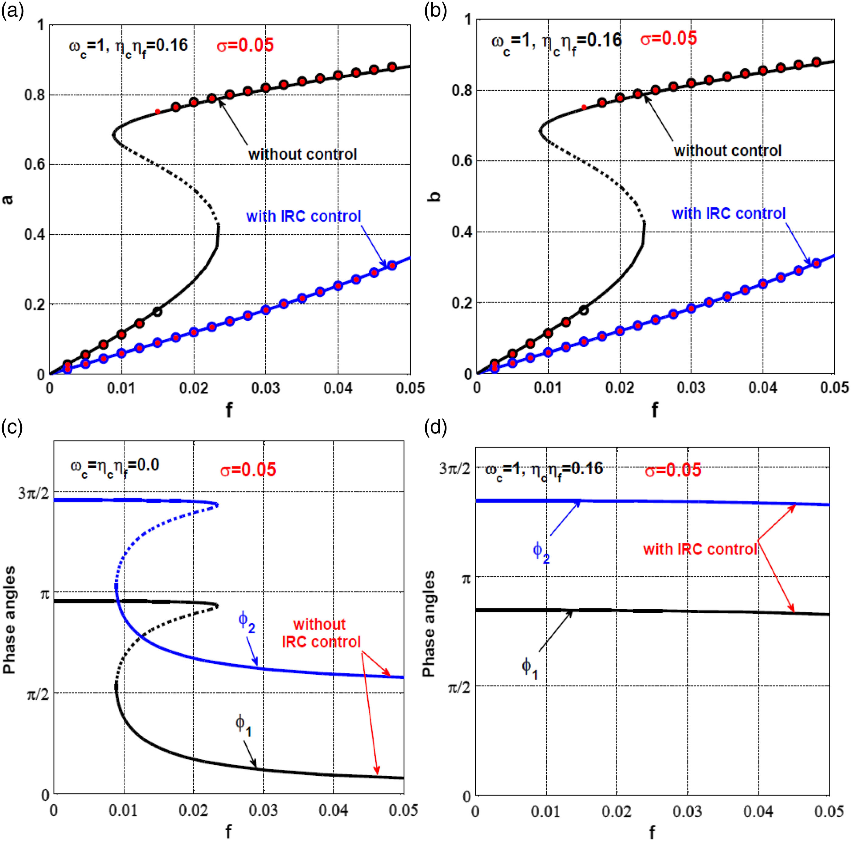
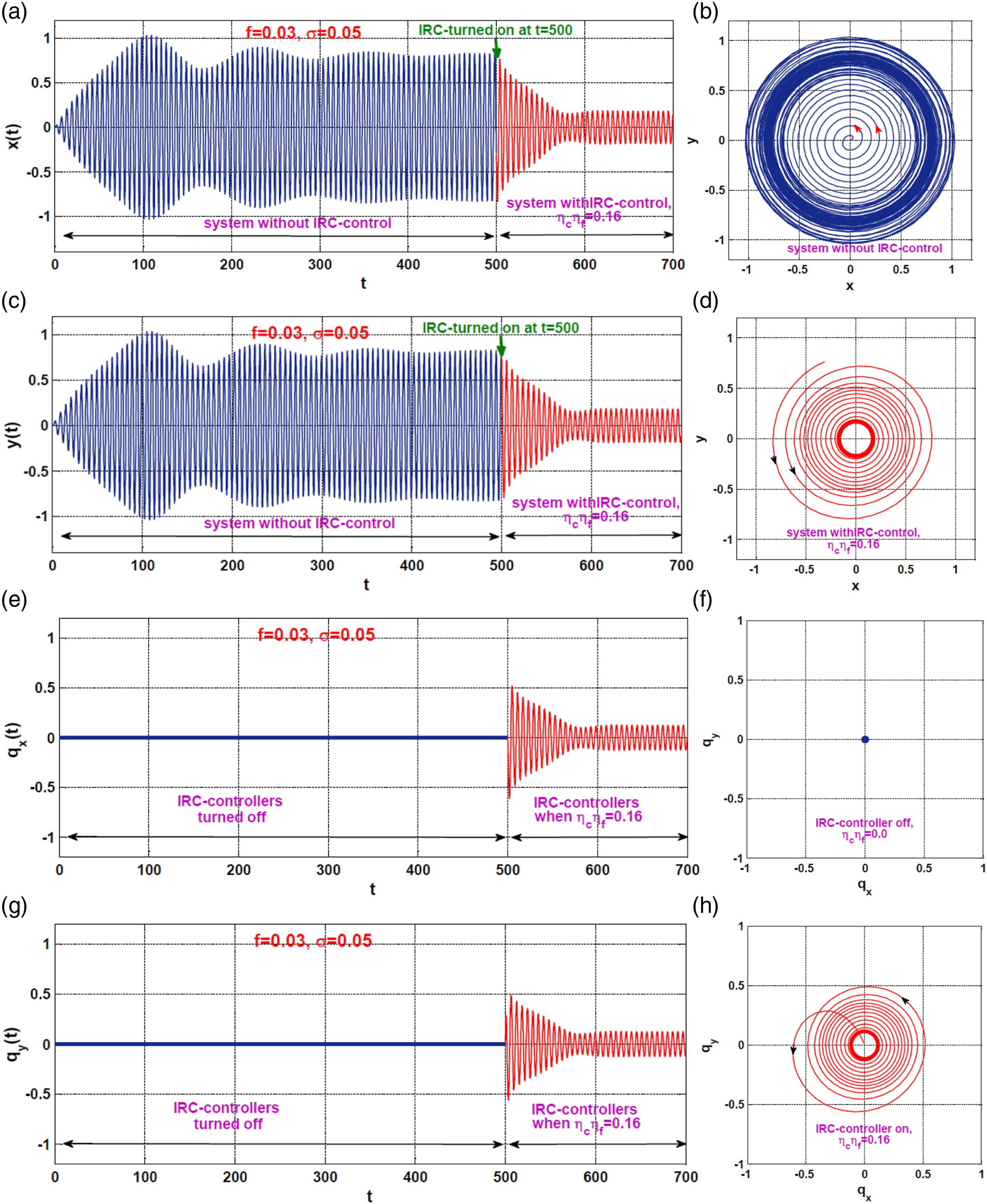
The system eccentricity response curve before and after control are compared as shown in Figure 17 and Figure 18 when and , respectively. It is clear from the figure that the coupling of the symmetric IRC to the rotor system has suppressed the strong lateral vibrations, and eliminated the bifurcation behaviors, regardless of the eccentricity and angular velocity magnitudes. In addition, the nonlinear relation between the oscillation amplitudes and the eccentricity before control has been turned to the linear form when the controller is activated. The system time-response is simulated in Figure 19 according to Figure 18 when (i.e., ) before and after activating the integral resonant controller. The figure simulates the evolution of the instantaneous oscillations of the rotor from to while the controller is turned off. At the time instant , the IRC controller has turned on to mitigate the system’s instantaneous oscillation. It is clear from Figures 19(a) and (c) that the steady-state oscillation amplitudes in and directions are before control and after control. Comparing these results (i.e., before control and after control) with Figure 18 when , one can demonstrate the excellent correspondence between analytical and numerical simulations.
12-pole system response curve , and : (a) vibration amplitude in direction, (b) vibration amplitude in direction., and (c, d) the steady-state phase angles.
12-pole system response curve , and : (a) vibration amplitude in direction, (b) vibration amplitude in \direction, and (c, d) the steady-state phase angles.
The temporal vibrations of the rotor system before and after control according to Figure 18 when and at zero initial conditions: (a, b, c) the rotor temporal oscillations in and directions before and after turning the controller on, (b) the system phase trajectory before control, (d) the system phase trajectory after turning the controller on, (e, g) the IRC temporal oscillations before and after turning the control on, (f) the IRC phase trajectory before turning the control on, and (h) the IRC phase trajectory after turning the control on.
Conclusions
In this study, the integral resonant controller is introduced along with PD-controller as a modified control methodology to suppress the lateral vibrations of the 12-pole system. The nonlinear dynamical model of the controlled system has been derived as a two-degree-of-freedom system coupled with two first-order differential equations. The obtained nonlinear model has been transformed to its dimensionless form to generalize the analyses and discussions. Then, the nonlinear algebraic system that governs the rotor steady-state oscillation amplitudes and the phase angles has been extracted using perturbation analysis. The influence of the different control parameters on the steady-state oscillation amplitudes has been explored through many bifurcation diagrams. In addition, the effect of failing one of the applied integral resonant controllers on the rotor dynamics has been also discussed. Moreover, the transient oscillations of the controlled system have been simulated numerically. According to the introduced analysis, we can conclude the following remarks:
(1)Integrating symmetric integral resonant controller to the rotor system has modified the linear damping coefficient to , where and .
(2)The system equivalent damping coefficient is proportional to both the derivative control gain () and the multiplication of both the control and feedback gains () of the symmetric integral resonant controller.
(3)The system equivalent damping coefficient is inversely proportional to both the position gain () and the square of the internal loop feedback gain ().
(4)According to remarks (1), (2), and (3), to get the best control performance for the combined IRC and PD controllers, the control parameters , and should be selected in a way that maximizes the function .
(5)The proposed symmetric resonant controller can efficiently suppress the lateral vibrations and force the nonlinear 12-pole system to perform forward circular whirling motion like the linear systems.
(6)The failure of one of the coupled integral resonant controllers may cause asymmetric oscillation for the rotor system, but the system does not lose its stability.
(7)Activating one of the applied integral resonant controllers while turning off the other one results in the breakdown of the bifurcation symmetry of the controlled system, which ultimately leads to different nonlinear phenomena such as the appearance of the localized and nonlocalized oscillation and the elliptic forward or/and backward whirling motions.
Footnotes
Declaration of conflicting interests
The author(s) declared no potential conflicts of interest with respect to the research, authorship, and/or publication of this article.
Funding
The author(s) disclosed receipt of the following financial support for the research, authorship, and/or publication of this article: The authors are grateful to the Raytheon Chair for Systems Engineering for funding this work.
ORCID iD
Nasser A Saeed
Appendix
References
1.
JiJCYuLLeungAYT. Bifurcation behavior of a rotor supported by active magnetic bearings. J Sound Vib2000; 235: 133–151, DOI: 10.1006/jsvi.2000.2916
2.
SaeedNAMahrousEAwrejcewiczJ. Nonlinear dynamics of the six-pole rotor-AMBs under two different control configurations. Nonlinear Dyn2020; 101: 2299–2323, DOI: 10.1007/s11071-020-05911-0
3.
SaeedNAAwwadEMEl-MeligyMA, et al.Radial versus cartesian control strategies to stabilize the nonlinear whirling motion of the six-pole rotor-AMBs. IEEE Access2020; 8: 138859–138883, DOI: 10.1109/ACCESS.2020.3012447
4.
JiJCHansenCH. Non-linear oscillations of a rotor in active magnetic bearings. J Sound Vib2001; 240: 599–612, DOI: 10.1006/jsvi.2000.3257
5.
JiJCLeungAYT. Non-linear oscillations of a rotor-magnetic bearing system under superharmonic resonance conditions. Int J Nonlinear Mech2003; 38: 829–835, DOI: 10.1016/S0020-7462(01)00136-6
6.
YangXDAnHZQianYJ, et al.Elliptic Motions and Control of Rotors Suspending in Active Magnetic Bearings. J Comput Nonlinear Dyn2016; 11: 054503, DOI: 10.1115/1.4033659
7.
El-ShourbagySMSaeedNAKamelM, et al.On the Performance of a Nonlinear Position-Velocity Controller to Stabilize Rotor-Active Magnetic-Bearings System. Symmetry2021; 13: 2069, DOI: 10.3390/sym13112069
8.
SaeedNAMahrousEAbouel NasrE, et al.Nonlinear dynamics and motion bifurcations of the rotor active magnetic bearings system with a new control scheme and rub-impact force. Symmetry2021; 13: 1502, DOI: 10.3390/sym13081502
9.
ZhangWZhanXP. Periodic and chaotic motions of a rotor-active magnetic bearing with quadratic and cubic terms and time-varying stiffness. Nonlinear Dyn2005; 41: 331–359, DOI: 10.1007/s11071-005-7959-2
10.
ZhangWYaoMHZhanXP. Multi-pulse chaotic motions of a rotor-active magnetic bearing system with time-varying stiffness. Chaos Solitons Fractals2006; 27: 175–186, DOI: 10.1016/j.chaos.2005.04.003
11.
ZhangWZuJWWangFX. Global bifurcations and chaos for a rotor-active magnetic bearing system with time-varying stiffness. Chaos Solitons Fractals2008; 35: 586–608, DOI: 10.1016/j.chaos.2006.05.095
12.
ZhangWZuJW. Transient and steady nonlinear responses for a rotor-active magnetic bearings system with time-varying stiffness. Chaos Solitons Fractals2008; 38: 1152–1167, DOI: 10.1016/j.chaos.2007.02.002
13.
LiJTianYZhangW, et al.Bifurcation of multiple limit cycles for a rotor-active magnetic bearings system with time-varying stiffness. Int J Bifurcation Chaos2008; 18: 755–778, DOI: 10.1142/S021812740802063X
14.
LiJTianYZhangW. Investigation of relation between singular points and number of limit cycles for a rotor–AMBs system. Chaos Solitons Fractals2009; 39: 1627–1640, DOI: 10.1016/j.chaos.2007.06.044
15.
El-ShourbagySMSaeedNAKamelM, et al.Control performance, stability conditions, and bifurcation analysis of the twelve-pole active magnetic bearings system. Appl Sci2021; 11: 10839, DOI: 10.3390/app112210839
16.
SaeedNAKandilA. Two different control strategies for 16-pole rotor active magnetic bearings system with constant stiffness coefficients. Appl Math Model2021; 92: 1–22.
17.
WuRZhangWYaoMH. Nonlinear vibration of a rotor-active magnetic bearing system with 16-pole legs. In: Proceedings of the International Design Engineering Technical Conferences and Computers and Information in Engineering Conference. Cleveland, OH, USA; 2017, DOI: 10.1115/DETC2017-67103
18.
WuRZhangWYaoMH. Analysis of nonlinear dynamics of a rotor-active magnetic bearing system with 16-pole legs. In: Proceedings of the International Design Engineering Technical Conferences and Computers and Information in Engineering Conference. Cleveland, OH, USA; 2017, DOI: 10.1115/DETC2017-67105
19.
WuRQZhangWYaoMH. Nonlinear dynamics near resonances of a rotor-active magnetic bearings system with 16-pole legs and time varying stiffness. Mech Syst Signal Process2018; 100: 113–134, DOI: 10.1016/j.ymssp.2017.07.033
20.
ZhangWWuRQSirigulengB. Nonlinear vibrations of a rotor-active magnetic bearing system with 16-pole legs and two degrees of freedom. Shock Vib2020; 2020: 5282904–5282929, DOI: 10.1155/2020/5282904
21.
MaWSZhangWZhangYF. Stability and multi-pulse jumping chaotic vibrations of a rotor-active magnetic bearing system with 16-pole legs under mechanical-electric-electromagnetic excitations. Eur J Mech A/solids2021; 85: 104120, DOI: 10.1016/j.euromechsol.2020.104120
22.
IshidaYInoueT. Vibration suppression of nonlinear rotor systems using a dynamic damper. J Vib Control2007; 13: 1127–1143, DOI: 10.1177/1077546307074577
23.
SaeedNA. On the steady-state forward and backward whirling motion of asymmetric nonlinear rotor system. Eur J Mech A/solids2019; 80: 103878, DOI: 10.1016/j.euromechsol.2019.103878
24.
SaeedNA. On vibration behavior and motion bifurcation of a nonlinear asymmetric rotating shaft. Arch Appl Mech2019; 89: 1899–1921, DOI: 10.1007/s00419-019-01551-y
25.
SaeedNAEissaM. Bifurcation analysis of a transversely cracked nonlinear Jeffcott rotor system at different resonance cases. Int J Acoust Vibration2019; 24(2): 284–302.
26.
SaeedNAAwwadEMEl-MeligyMA, et al.Sensitivity analysis and vibration control of asymmetric nonlinear rotating shaft system utilizing 4-pole AMBs as an actuator. Eur J Mech A/solids2021; 86: 104145, DOI: 10.1016/j.euromechsol.2020.104145
27.
SaeedNAAwwadEMEl-MeligyMA, et al.Analysis of the rub-impact forces between a controlled nonlinear rotating shaft system and the electromagnet pole legs. Appl Math Model2021; 93: 792–810, DOI: 10.1016/j.apm.2021.01.008
28.
SrinivasRSTiwariRKannababuCh. Application of active magnetic bearings in flexible rotordynamic systems – a state-of-the-art review. Mech Syst Signal Process2018; 106: 537–572.
29.
DiazIMPereiraEReynoldsP. Integral resonant control scheme for cancelling human-induced vibrations in light-weight pedestrian structures. Struct Control Health Monit2012; 19: 55–69.
30.
Al-MamunAKeikhaEBhatiaCS, et al.Integral resonant control for suppression of resonance in piezoelectric micro-actuator used in precision servomechanism. Mechatronics2013; 23: 1–9.
31.
MacLeanJDJSumeetSA. A modified linear integral resonant controller for suppressing jump phenomenon and hysteresis in micro-cantilever beam structures. J Sound Vibration2020; 480: 115365.
32.
OmidiEMahmoodiSN. Nonlinear integral resonant controller for vibration reduction in nonlinear systems. Acta Mech Sin2016; 32: 925–934.
33.
OmidiEMahmoodiSN. Sensitivity analysis of the Nonlinear Integral Positive Position Feedback and Integral Resonant controllers on vibration suppression of nonlinear oscillatory systems. Commun Nonlinear Sci Numer Simulat2015; 22: 149–166.
34.
OmidiEMahmoodiSN. Nonlinear vibration suppression of flexible structures using nonlinear modified positive position feedback approach. Nonlinear Dyn2015; 79: 835–849.
35.
SaeedNAMoatimidGMElsabaaFM, et al.Time-delayed nonlinear integral resonant controller to eliminate the nonlinear oscillations of a parametrically excited system. IEEE Access2021; 9: 74836–74854.
36.
SaeedNAMohamedMSElaganSK, et al.Integral resonant controller to suppress the nonlinear oscillations of a two-degree-of-freedom rotor active magnetic bearing system. Processes2022; 10(2): 271.
37.
ZhongZDuanYCaiZ, et al.Design and cosimulation of twelve-pole heteropolar radial hybrid magnetic bearing. Math Probl Eng2021; 8826780: 1–14.
38.
NayfehAHMookDT. Nonlinear Oscillations. New York, NY, USA: Wiley, 1995, DOI: 10.1002/9783527617586
39.
NayfehAH. Resolving controversies in the application of the method of multiple scales and the generalized method of averaging. Nonlinear Dyn2005; 40: 61–102, DOI: 10.1007/s11071-005-3937-y
40.
AnjumNHeJHAinQT, et al.Li-he’s modified homotopy perturbation method for doubly-clamped electrically actuated microbeams-based microelectromechanical system. FACTA UNIVERSITATIS (Series: Mech Engineering)2021; 19(4): 601–612.
41.
HeJHEl-DibYO. The enhanced homotopy perturbation method for axial vibration of strings. FACTA UNIVERSITATIS (Series: Mech Engineering)2021; 19(4): 735–750.
42.
HeJHYangQHeCH, et al.A simple frequency formulation for the tangent oscillator. Axioms2021; 10: 320.
43.
HeJHEl-DibYOMadyAA. Homotopy perturbation method for the fractal toda oscillator. Fractal Fract2021; 5: 93.
44.
IshidaYYamamotoT. Linear and Nonlinear Rotordynamics: A Modern Treatment with Applications. 2nd ed. New York, NY, USA: Wiley-VCH Verlag GmbH & Co. KGaA, 2012, DOI: 10.1002/9783527651894
45.
SchweitzerGMaslenEH. Magnetic Bearings: Theory, Design, and Application to Rotating Machinery. Berlin/Heidelberg, Germany: Springer, 2009, DOI: 10.1007/978-3-642-00497-1