
Abstract
Hermetic digital scroll compressor has been widely used as a small-scale organic Rankine cycle application in the heating, ventilation, and air conditioning systems. A clunking noise issue is recently found in an air conditioning outdoor unit, and the main cause of the noise is experimentally identified to be the impact of the scrolls in the compressor unit during the switching process. The semi-active control methods are thus designed to greatly reduce the noise level by using additional valves to adjust the pressure changing rate within the modulation chamber. The response time for the impact of the scrolls can then be controlled by the added valves. The additional release valve with a smaller diameter pipe parallel to the main valve is tested firstly for its performance. Slower flow rate is produced and the pipe can extend the response time and decrease the speed of the impact process by reducing the pressure changing rate. The use of a discharge valve is also tested for controlling the pressure changing rate inside the chamber. The discharge valve with an opposite effect to the release valve is found useful for solving the noise issue. Both noise and vibration results confirm that the impact noise in the frequency range of interest can be reduced by using the proposed semi-active control methods.
Introduction
As a small-scale organic Rankine cycle application, hermetic digital scroll compressor has been widely used in the air conditioning due to its advantages of reliability, efficiency, and low cost compared to the inverter type compressor.1–3 However, several models of the digital scroll compressors used in an air conditioning outdoor unit may generate unacceptable levels of clunking noises during operations.
Figure 1 shows the schematic of a simplified digital scroll compressor according to the corresponding model designs.4–6 A solenoid valve is used to control the two working states of the compressor, namely loaded and unloaded. When the valve is opened, the modulation chamber holds the pressure at the same level as the suction pressure chamber, and the spring mechanism component within the compressor pushes the up-scroll upwards and separates from the rotating low-scroll. The compressor is then in an unloaded status. When the valve is closed, the pressure in the modulation chamber will slowly increase due to the small throughway (about 1 mm diameter) from the high-pressure chamber to the modulation chamber. Due to the high pressure difference between the low-pressure suction chamber and the high-pressure modulation chamber, the pressure differential force overcomes the spring force and then the up-scroll is pushed downwards and coincides with the low-scroll. The compressor is then in a loaded status. During both processes, the motion of the up-scroll would lead to an impact and potentially make the clunking noises as stated.
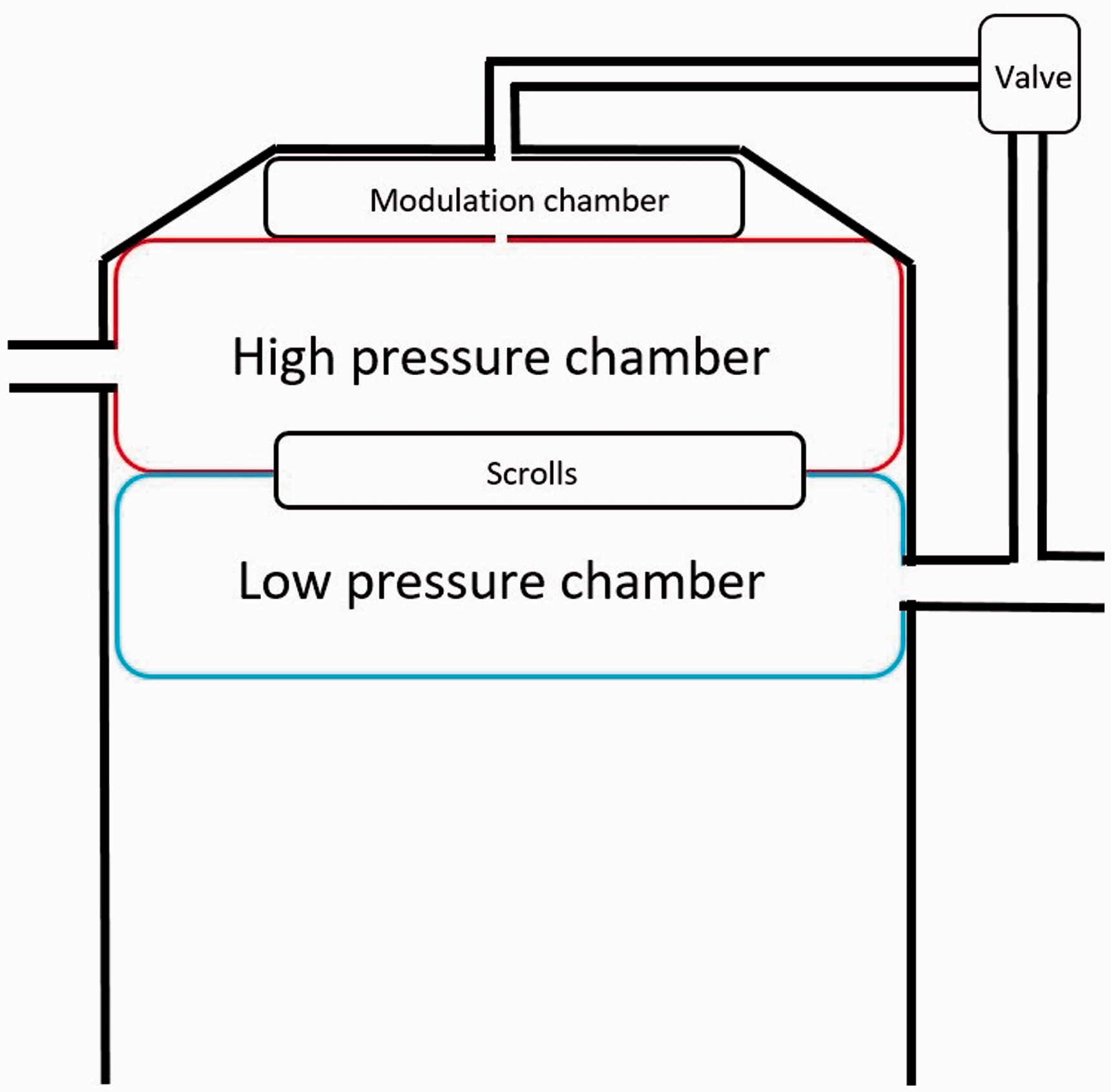
Schematic of digital scroll compressor.
This could be the main reason as the clunking noise found when the compressor is in switching states. The main challenges for addressing this clunking noise issue are in three aspects. Firstly, due to the nature of a hermetic compressor, it cannot be opened to repair or modify its inside structure. Secondly, the clunking noises are found in low frequency range, where most acoustic absorbing materials have little effect on the low-frequency noises.7–10 Lastly, the unsteady flows are characterized by in-and-out states of the compressor unit, and the pressure conditions can be complex in all chambers during different running conditions.11,12 Thus, the main aim of this paper is to design effective control strategies to attenuate the clunking noise levels during the switching process of operation. The semi-active control methods to be considered in this paper are the use of one release valve or one discharge valve to control the pressure changing rate within the modulation chamber. It is found that the control methods are able to reduce the clunking noise of the digital scroll compressors to an acceptable level.
The analysis of noise source in a working compressor
The compressor studied is a digital scroll compressor. The vibration and noise measurements of an example unit are shown in Figure 2, where two noises can be found. It is noticed that the noise level from the compressor when changing from the unloaded to loaded status is much higher than that when changing from the loaded to unloaded status. The noise pressure level is increased dramatically during the switching process and can be increased up to 0.35 Pascal when the solenoid valve is opening or closing.
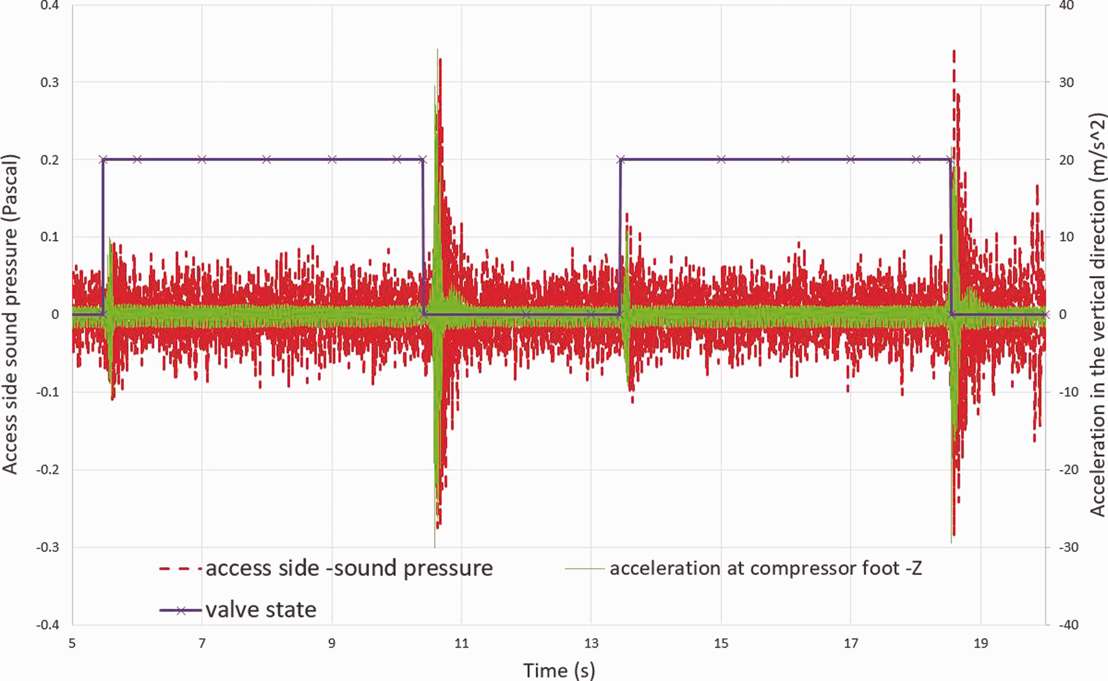
Vibration (green line) and noise (red dash line) time-history signals in the operating system.
By using the Artemis, a multi-channel analysis software from HEAD acoustics, the spectrum analysis of the time-history sound signal indicates that the impact knocking sound has the concerned frequency range at 150–200 Hz for most models. Figure 3 shows the noise spectrum comparison between the sound with knocking component and the sound without knocking component by using the fast fourier transform (FFT) algorithm. It can be clearly seen that there is about 10 dB difference around 160 Hz. There also exist some differences in the middle frequency (700 Hz) and high frequency (1200–1600 Hz) ranges. Figure 4 shows the overall sound level dB(A) during the operations of system with different capacities. Different capacities demonstrate the pressure differences between the high-pressure and the low-pressure sides of the modulation chamber. This indicates that the noise level can be decided by the pressure inside of the chamber.
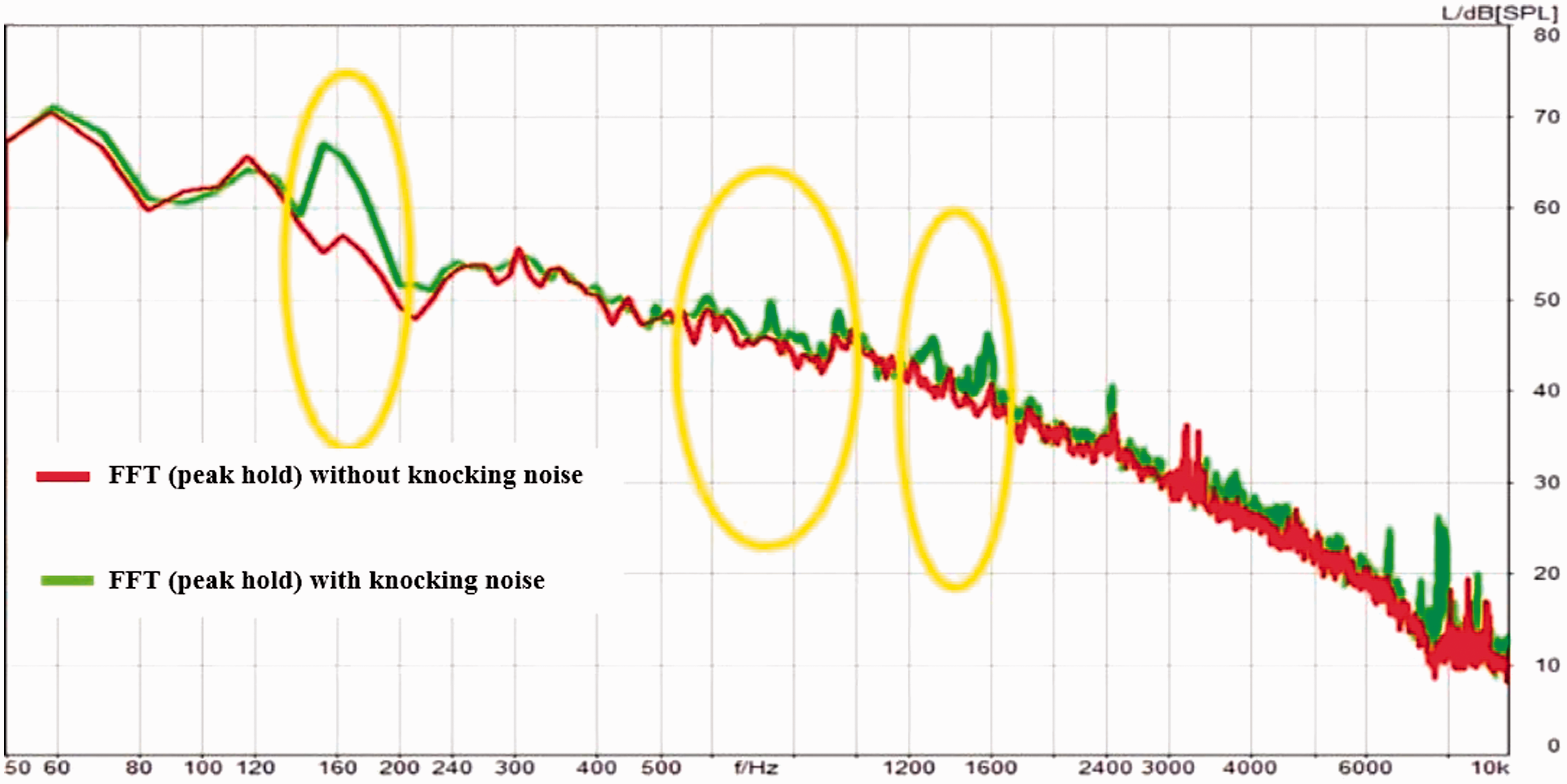
Comparison of noise spectrum with knocking (green) and without knocking (red).
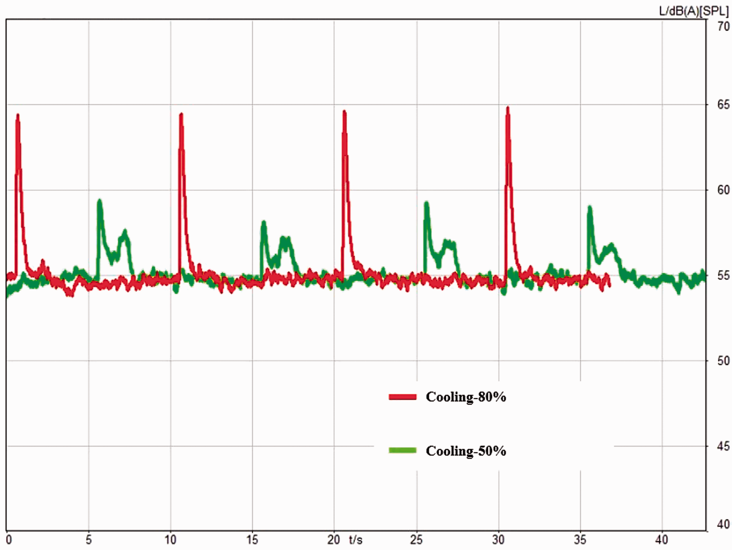
Noise level dB(A) during the operations of system with different capacities: 80% (red) and 50% (green).
In particular, the semi-active control method by using a release valve or a discharge valve without modifying on the compressor can be used to control the pressure changing rate during the switching process, thus the contact speed of the scrolls can be controlled and then the purpose of the noise source control can be achieved.
Experiment descriptions
A total of three tests are conducted to study the effects of the additional valves. A system identification test is first carried out under a non-operating condition. Then the effects of two types of additional valves are examined in an operating system. Since the hermetic compressor cannot be modified, the system identification test will be processed first to study the boundary conditions and component parameters. Although the pressure conditions can be complex in the chambers during working condition, the pressure at boundary conditions of the compressor would be fixed due to its component mechanism. The semi-active control model and controlling methods will be designed based on the results of the system identification tests. The effectiveness of the designs can then be evaluated.
In the system identification test, a compressed air cylinder is used to provide a constant high-pressure gas directly into the high-pressure chamber. The low-pressure chamber is directly connected to the atmosphere, where it can be considered as at a steady pressure level. A pressure sensor is placed at the modulation chamber to monitor its pressure change. The test rig is shown in Figure 5. A manual digital control system, independently from the original operating system, is programmed by using the LabVIEW. 13 The new control system can directly control the open/close state up to three different valves. Each valve is independent from others. The output signals are designed to be repeated cycles to simulate the working state of the compressor. The pressure in the modulation chamber and the vibration in the scroll impact direction are measured and analyzed.
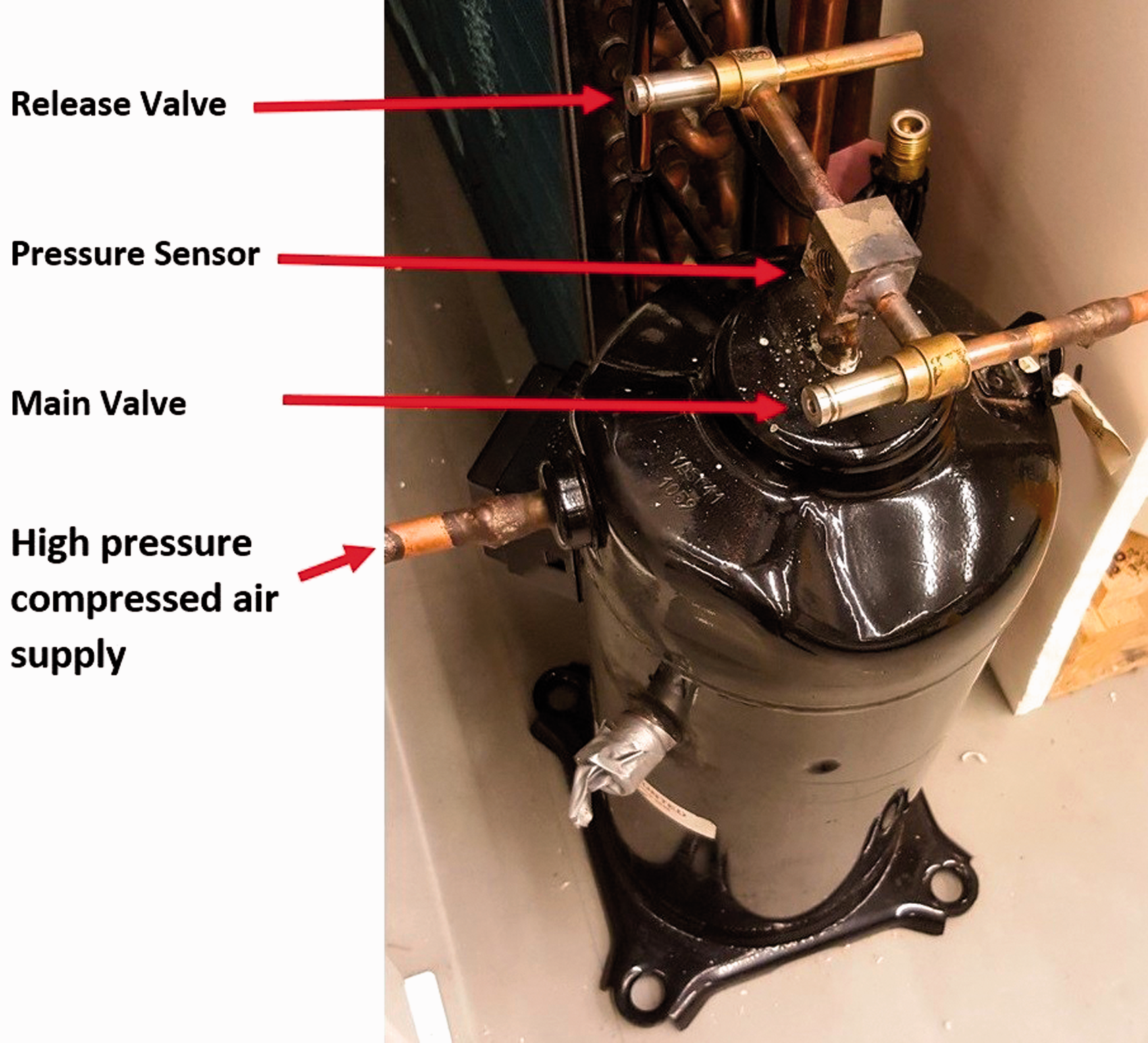
Test rig of the system identification test.
In the original operating system, the main valve is regulated by the main control system. Several probes are used to monitor the pressures in the system and the environment temperature. According to the feedback from the probes, the main control system decides the open/close state of the main valve. By applying the new semi-active control method, both the original main valve and the additional valves are controlled by the new control system. The capacity of the compressor can be designed and manually input. The feedback from the probes are still input into the main control system, but the output control signal to the main valve is replaced by the new system. A block diagram of the new control system combining with the original system is shown in Figure 6.
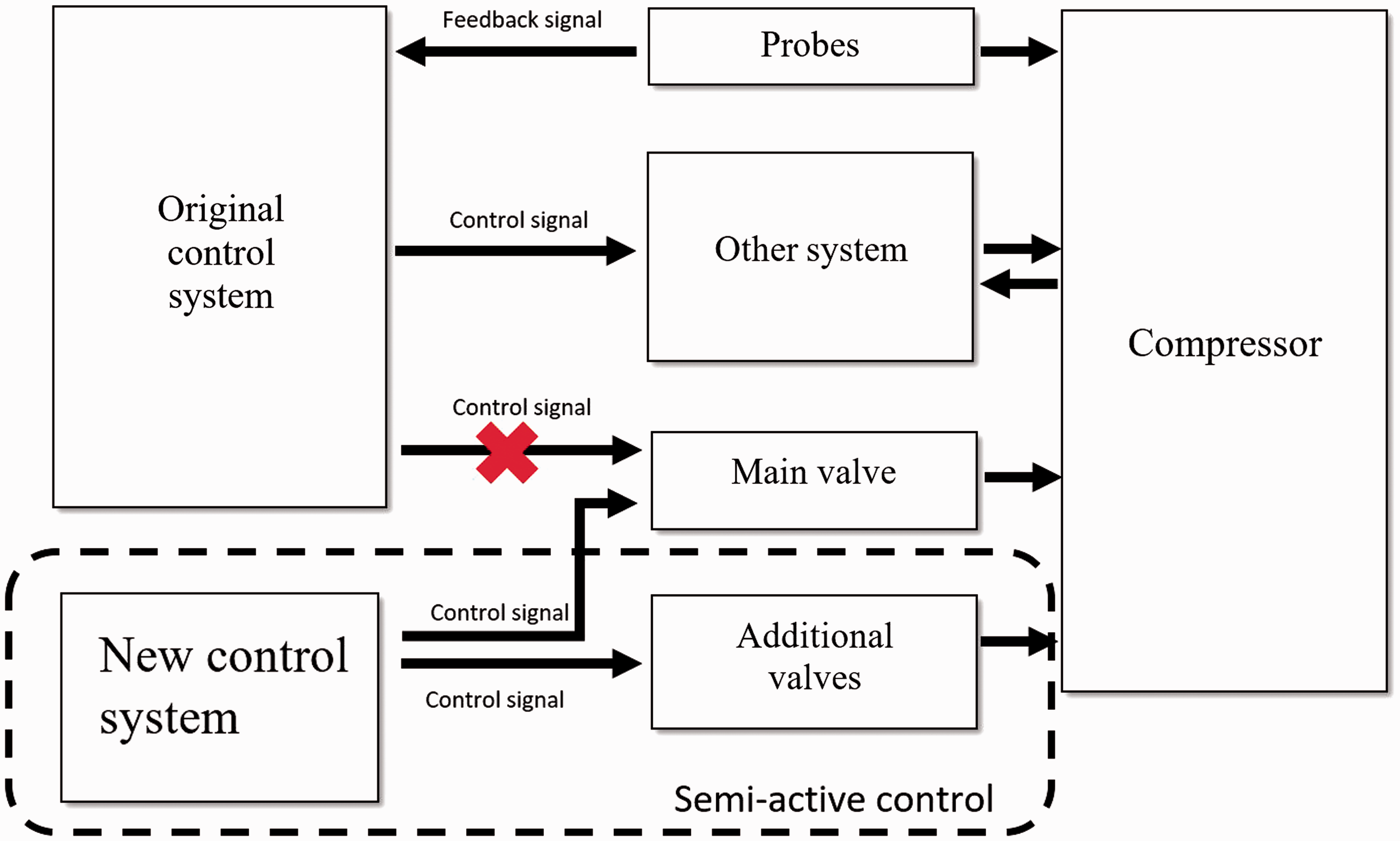
Block diagram of the new control system.
To measure the vibration and noise from the compressor, a total of three channels are used in the model tests. Since the noise is mainly produced due to the vertical motion of the scrolls and their impacts, two accelerometers are located on the compressor top and foot to measure the accelerations in the vertical direction. The comparison of the results of the two accelerometers can be used to indicate the rotation of the compressor. One microphone is placed 0.5 m high and 0.5 m away from the compressor. The baseline results are recorded before and after activating the additional valves and can be compared to check the repeatability of the experiments.
Two types of additional valves are designed according to their locations and purposes. The released valve is applied parallel to the original valve. A needle valve with a smaller diameter pipe is also attached to adjust the flow through the effective area size. By considering the relationship between the flow rate and the pressure drop, a 1 mm diameter tube is required to be used to connect the chamber to the suction pipe (low-pressure side) directly, as shown in Figure 7. With a new controlling system and by using the released valve with capillary tubes, the pressure change rate can be reduced. A discharge valve connects the modulation chamber to the high-pressure discharge outlet, as shown in Figure 7. The discharge valve is used to increase the pressure changing rate and shorten the impact response time. Although the impact noise may still exist, but its frequency is increased and then can be absorbed easily by the acoustic absorbing materials.
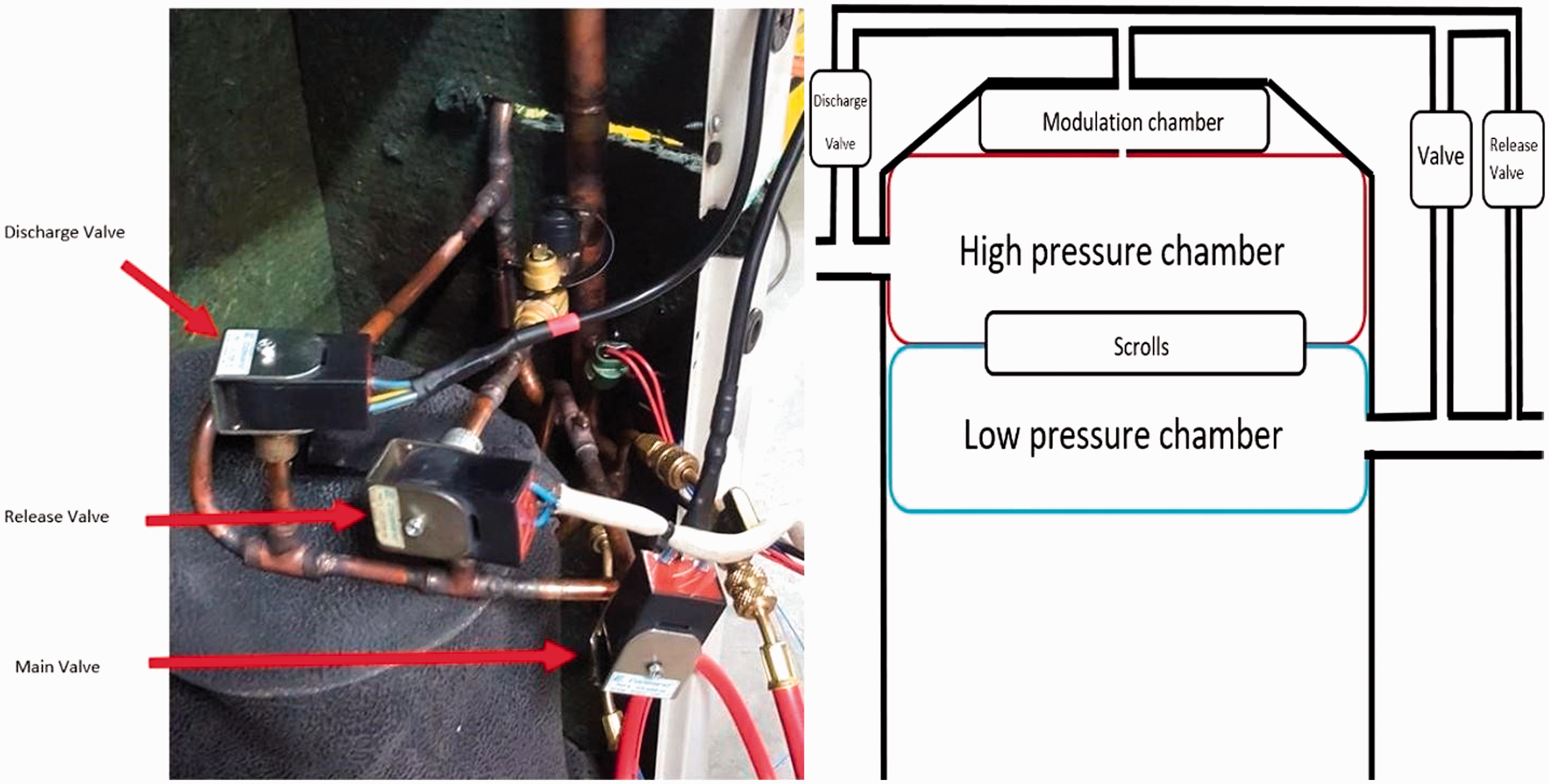
Valve test rig of the operating system.
Test procedure and result analysis
System identification test
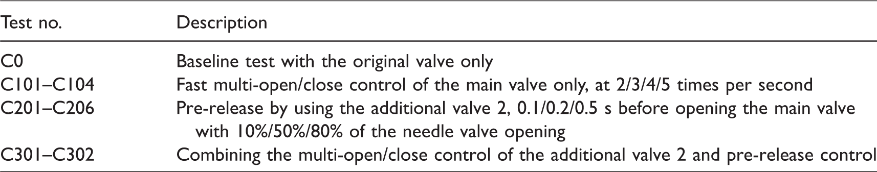
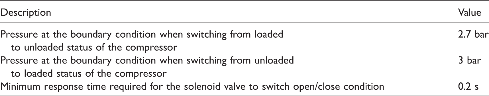
After a series of system identification tests, some test methods and results are listed in Tables 1 and 2, respectively. The pressures at changing loaded/unloaded status are found to be 2.7–3.0 bar, which means the up-scroll moves up or down at 2.7–3.0 bar pressure difference between the inside and the outside of the modulation chamber (each outlet: discharge or suction outlet). Figure 8 shows the pressure changes when using different controlling methods. It can be seen that the maximum pressure changes have been reduced with the C204 (0.2 s per-release) method. For the C301 (0.2 s per-release with a 4 times/s multi-open/close) controlling method, a variation of the pressure is found before the main valve is opened and the maximum pressure change is also reduced. However, this control method may damage the valve and shorten its lifecycle. The test method C204 has shown a good result of the pressure control where the low peak has been reduced in comparison with others.
Example of the test methods.
System identification.
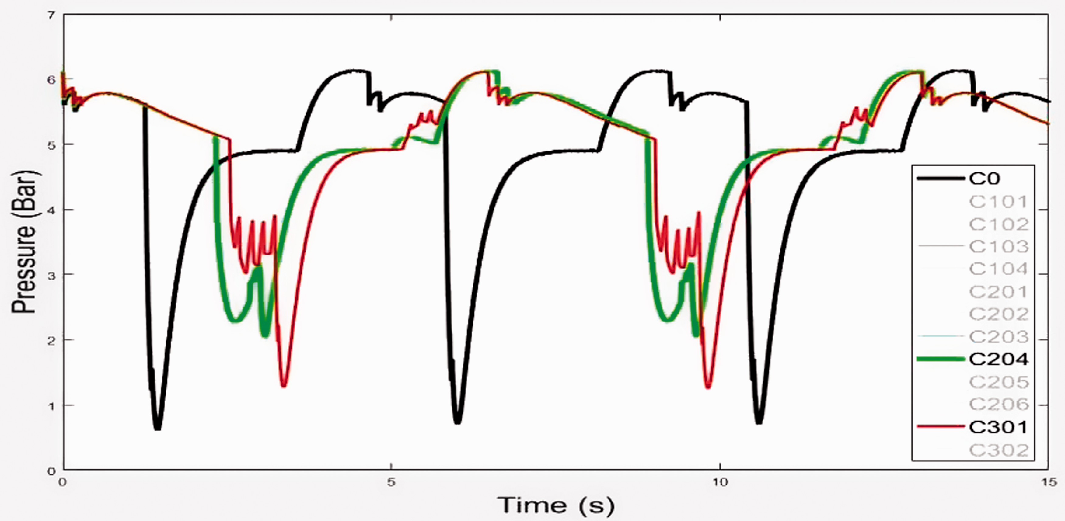
Pressure changes in in the modulation chamber: C0, baseline (black); C204, 0.2 s per-release (green); and C301, 0.2 s per-release with a 4 times/s multi-open/close (red).
Operating system test
Release valve
The controlling method is then tested on a running air conditioning unit. Figure 9 shows the sound spectrum holography. It can be clearly seen that the knocking component (as indicated area) is reduced significantly from 60 dB(A) to 46 dB(A). The impact noise became unnoticeable. However, the compressor presents a louder rattling sound (250–350 Hz) under the loaded status. The reason could be the pressure difference inside the chamber and the suction outlet is not big enough to hold the two scrolls contacted tightly and continuously. The instability contact (the pressure differential force equal or almost equal to the spring force) of the two scrolls due to the small pressure difference between the chamber and the suction outlet could lead to the louder rattling sound. Figure 10 shows the vibration spectrum holography at compressor foot location. The vibration spectrum exhibits the same behavior as the noise signal does. From both noise and vibration performances, it is clear that a release valve with the original valve control can avoid the impact noise/vibration of the scrolls but may also lead to an additional rattle noise/vibration under the loaded status. The new rattle noise/vibration was found at higher frequency range and caused outside the compressor, which will be discussed in this paper.
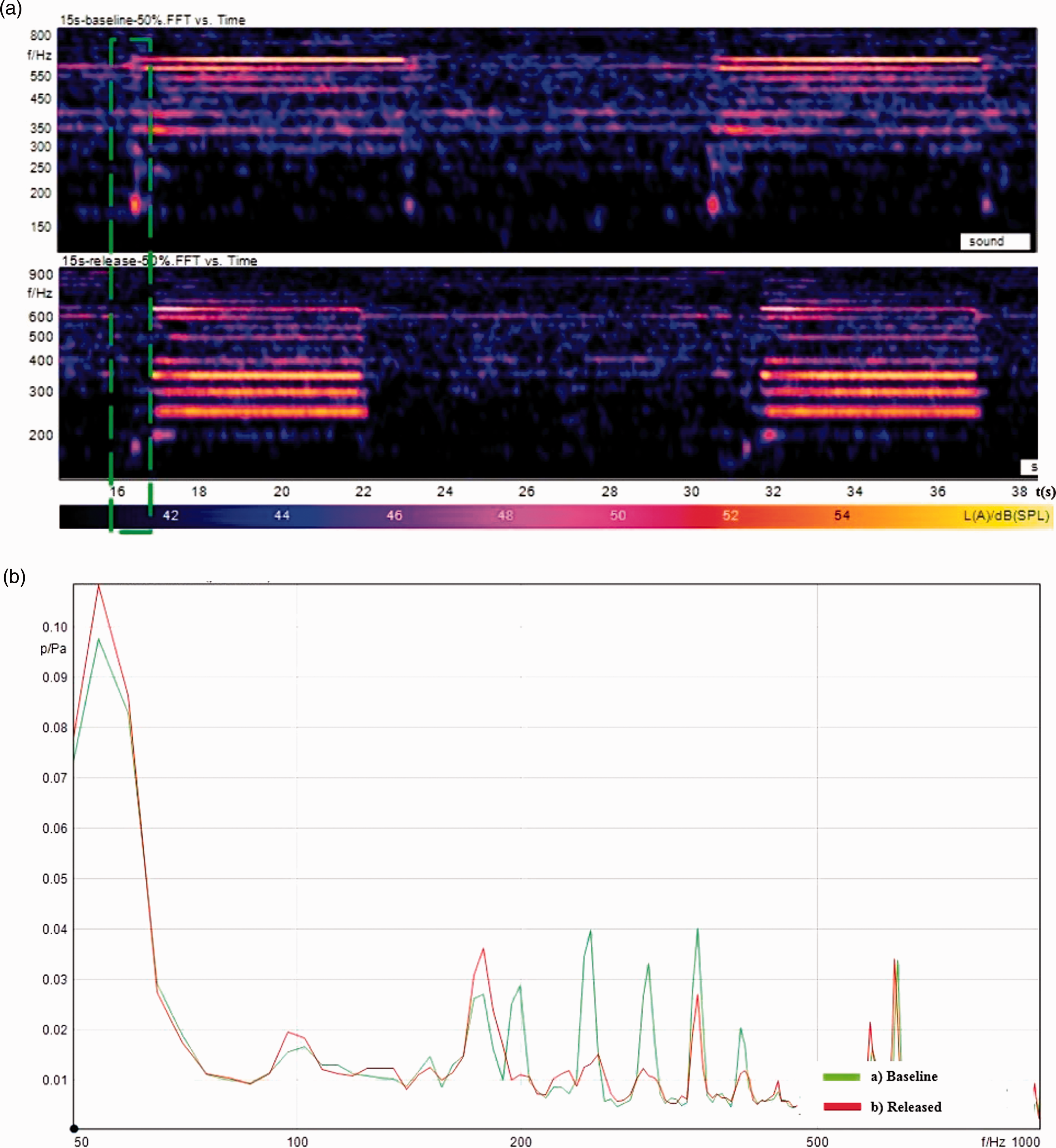
Noise spectrums and their FFT comparisons using C204 on the operating system: (a) baseline and (b) C204 released.
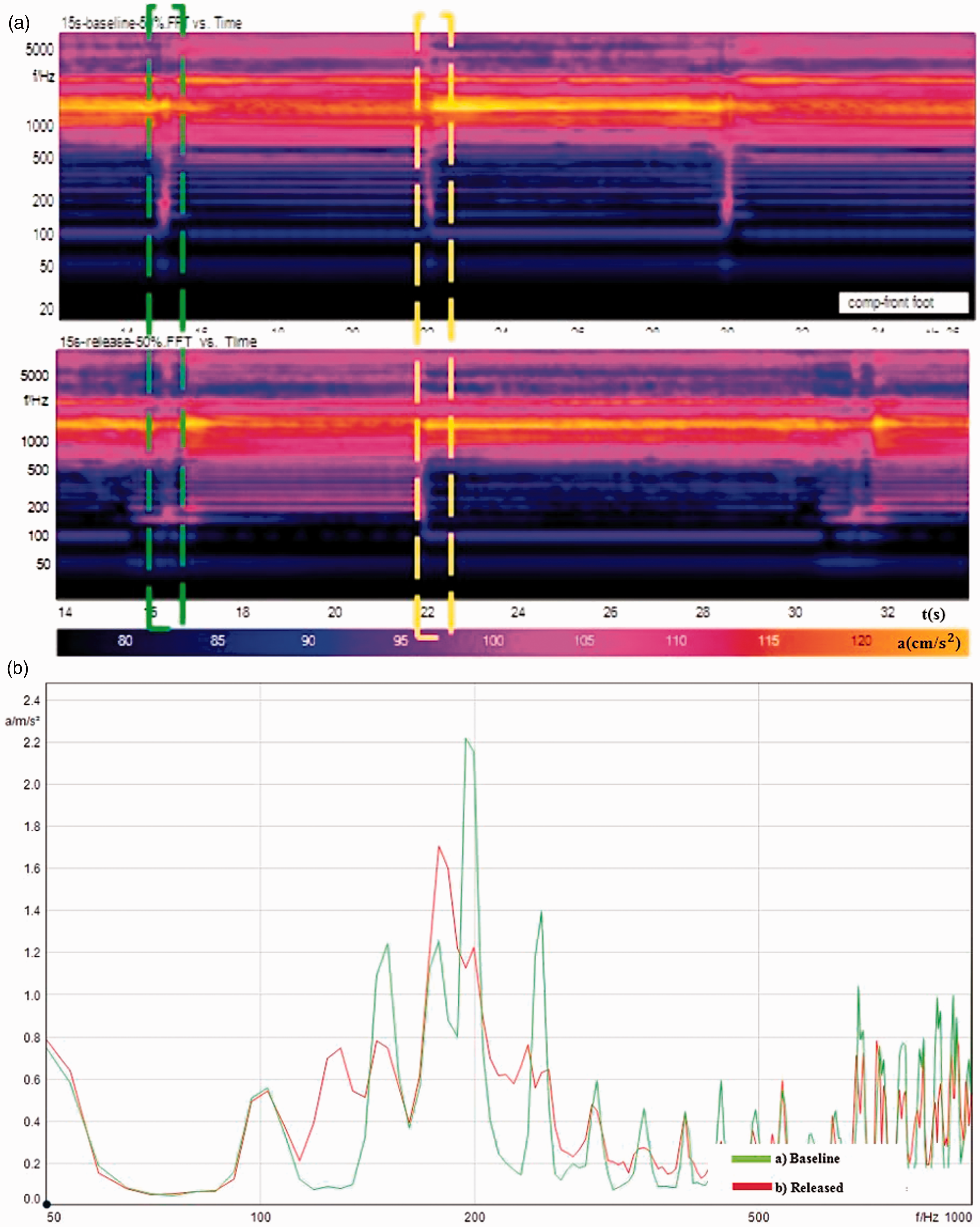
Vibration spectrums and their FFT comparisons using C204 on the operating system: (a) baseline and (b) C204 released.
Discharge valve
Three types of controlling methods are tested for the discharge valve and compared to the original operating system, namely discharge valve and main valve open/close and close/open at the same time; discharge valve opens at 0.1 s before the main valve closes and closes at 1 s after the main valve closes; discharge valve opens at 0.2 s before the main valve closes and closes at 1 s after the main valve closes. The noise performances are shown in Figure 11. It can be easily noticed that all methods are effective. The impact noises are eliminated when switching from the unloaded to loaded status and are very slightly increased when switching from the loaded to unloaded status. The FFT comparison shown in Figure 12 indicates that, by using the discharge valve, a pre-pressure in the modulation chamber before the closing of the main valve is helpful to the noise reduction. It is found that the advanced opening time of the discharge valve before the main valve closing should be no longer than 0.1 s. Further tests of different operating strategies are processed with 0.1 s pre-open and 0.5 s post-close, 0.1 s pre-open and 0.2 s post-close, opposite operation to the main valve. From those results, no much differences for the knocking sound improvement are found among those configurations. Specifically, the time to close the discharge valve after the main valve is closed is not very important. The reason is that the pressure level in the modulation chamber would increase quickly to the pressure level in the high-pressure chamber under the operation of both the discharge valve and the main valve. The time for the delay closing of the discharge valve is suggested to be 0.5 s by considering the minimum response time of the valve for opening/closing and cooling issues. Meanwhile, from practical point of view, the opposite operation to the main valve is easier to be implemented from the system control point of view.
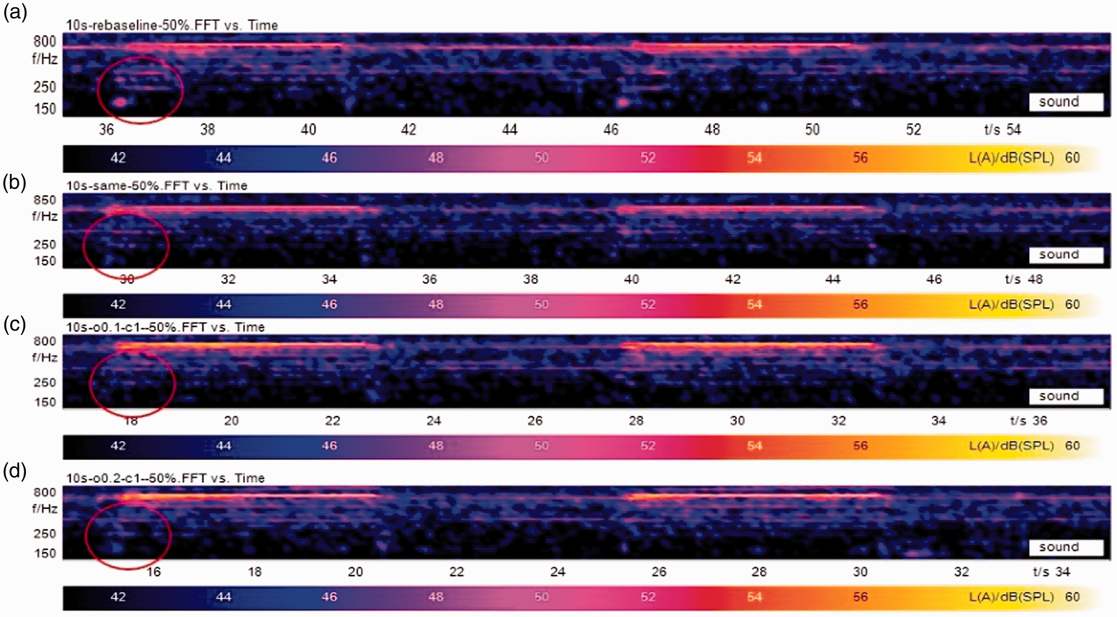
Noise performances of the discharge valve: (a) baseline; (b) 0.1 s pre-open and 0.5 s post-close; (c) 0.1 s pre-open and 0.2 s post-close; and (d) opposite operation.
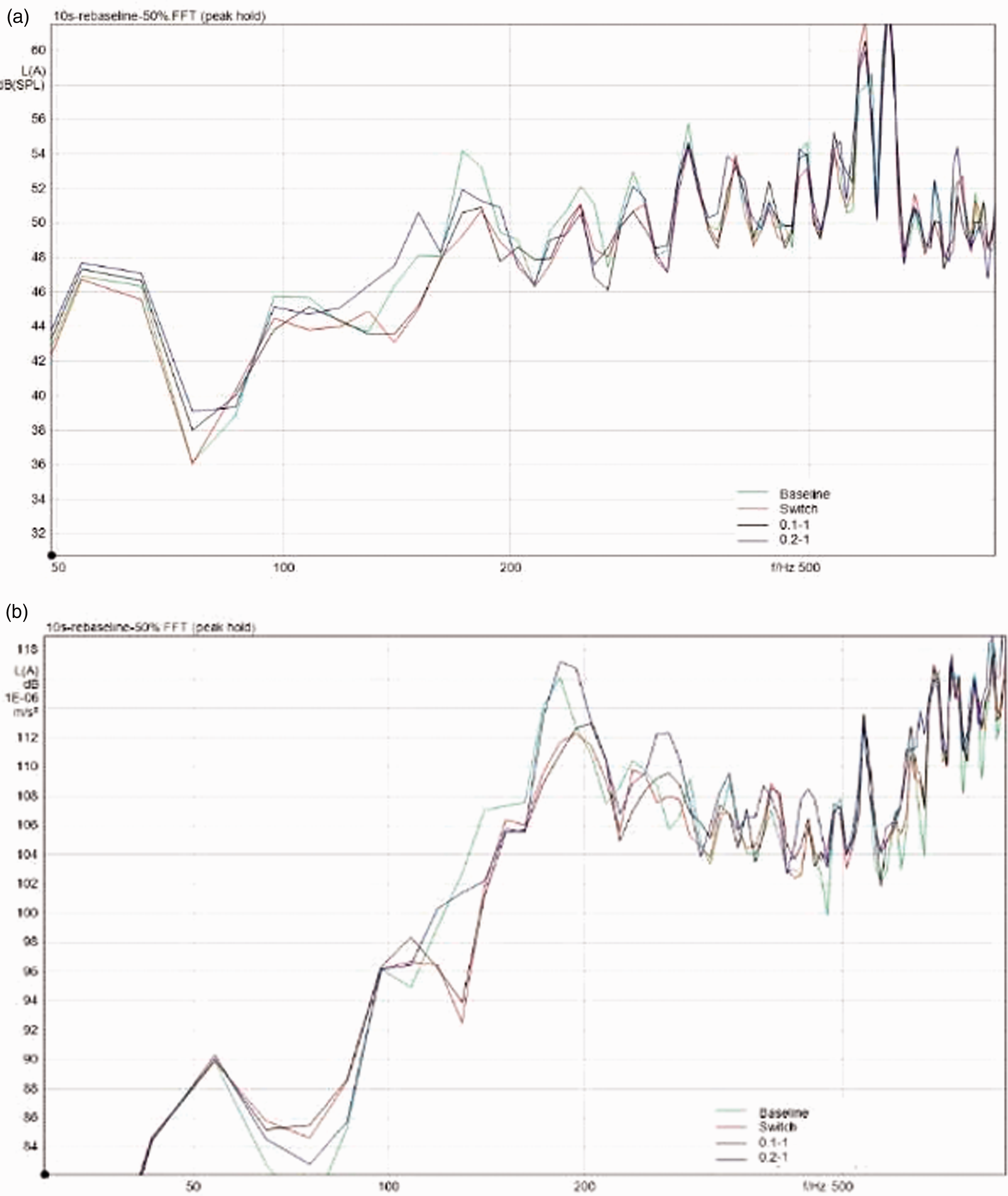
Comparison of the noise and vibration performances of the discharge valve using different methods: (a) baseline (green); (b) 0.1 s pre-open and 0.5 s post-close (black); (c) 0.1 s pre-open and 0.2 s post-close (blue); and (d) opposite operation (red).
Based on the experimental observations, the additional discharge valve control strategy is the most practical and effective option. Figure 13 shows the comparison of the sound pressure level with and without the added discharge valve opposite operation to the main valve. In the switching from the unloaded status to the loaded status, the knocking sound level (peak at the blue-graph) can be reduced by approximately 5 dB(A) compared to the sound level (peak at the red-graph). There is a slight increase on the knocking sound level from the loaded status switching to the unloaded status. The reason could be a higher pressure level inside the modulation chamber while adding a discharge valve. The higher pressure level inside the modulation chamber could lead to the larger pressure differential between the modulation chamber and the suction port at the time when switching from load to unload status.
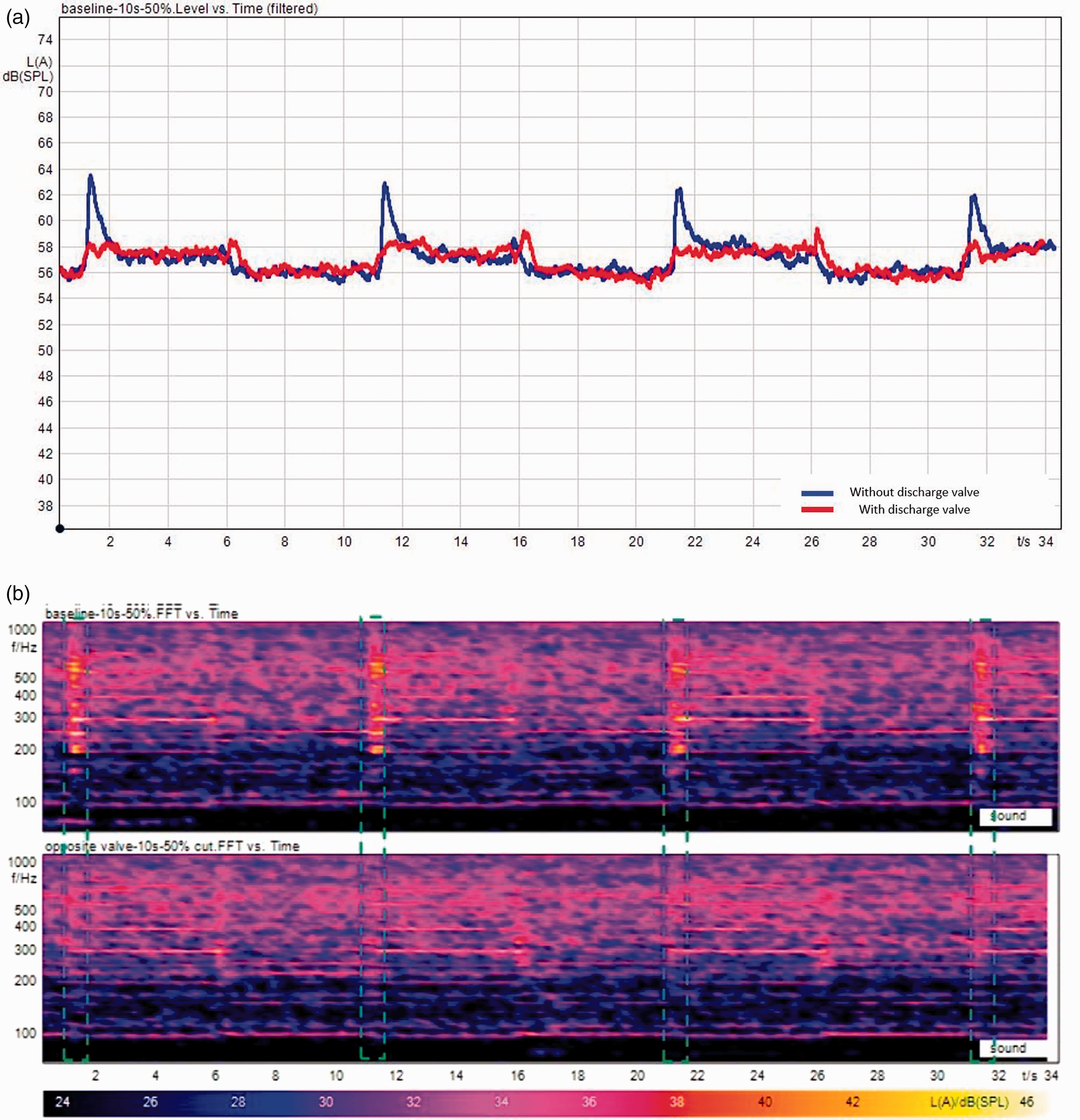
Noise level and noise spectrum comparison with and without the added discharge valve: (a) baseline (blue) and (b) discharge valve (red).
Conclusion
This paper conducted a series of experimental tests for the additional valves designed for the noise control of the digital scroll compressor in an air conditioning unit. The semi-active control methods were implemented to control the pressure changing rate in the modulation chamber of the compressor during the status switching processes. Thus, the contact speed of the scrolls and the noise issue can be controlled. The additional release valve with smaller diameter pipe parallel to the main valve was used to reduce flow rate and the pressure change rate, extend the response time and decrease the speed of the impact process. From the test results in the operating system, the impact noise (clunking noise) was eliminated but sometimes another long rattling noise was produced due to the contact of the rotating scrolls. The use of a discharge valve was found useful for noise reduction. A short time (0.1 s) discharge process before the closing time of the main valve could increase the flow rate into the modulating chamber and accelerate the impact process. The noise and vibration results showed that the impact noise in the low frequency range was eliminated when switching from the unloaded status to the loaded status.
Although either the release valve or the discharge valve could be able to reduce the noise in the low frequency range, there are still unknown impact factors, such as the environmental conditions. The final optimization would depend on the site ambient environment, weather, and working conditions.
Footnotes
Acknowledgements
The authors would like to thank the two reviewers for their suggestions and comments on improving the quality of this paper.
Declaration of conflicting interests
The author(s) declared no potential conflicts of interest with respect to the research, authorship, and/or publication of this article.
Funding
The author(s) disclosed receipt of the following financial support for the research, authorship, and/or publication of this article: This work was supported by Australian Government Department of Industry, Innovation and Science through its Innovation Connection scheme.