
Abstract
The broad application of steel and steel-concrete bridges has caused significant vibration and noise problems. Although the channel steel-concrete composite girder is a commonly used bridge type, the vibration transmission performance and structural optimization design (concrete deck, stiffeners, transverse connection components, etc.) from the perspective of vibration control have not been well studied. In this paper, experimental and numerical approaches are combined to investigate the dynamic properties of a steel-channel girder in the audible frequency range (20–2000 Hz). A steel-channel girder is tested via hammering. The effects of damping, stiffeners, and a concrete deck on structural vibration are evaluated using the finite element method. The experimental results indicate negligible differences in the vibration responses on a single plate, but large differences at different sections. The results are influenced by the effects of the distance and transmission path. The numerical results reveal that increasing the damping and stiffness (e.g., setting stiffeners) are both effective in reducing vibrations. Furthermore, increasing the stiffness has a more prominent effect on structural vibrations and their frequency dependence, whereas increasing the damping ratio can stably reduce structural vibrations. The simulation results indicate that installing a concrete deck is the most effective approach to vibration reduction, as it can decrease overall vibration by more than 10 dB. Vertical web stiffeners have stronger effects on vibration reduction than other stiffening countermeasures (e.g., transverse connection components and longitudinal bottom plate stiffeners).
Introduction
In rail transit development, steel bridges are widely used in bridge construction because they can be erected quickly. Steel box sections have become more common than I-shaped sections in rail transit composite bridges because of their excellent stabilities and greater torsional stiffnesses. Figure 1 shows a prefabricated channel steel girder and its vibration transmission pattern during train operation. Research has shown that a train crossing a bridge typically produces more noise than a train running on normal track at ground level. The increase can commonly be 10 dB or more, with steel bridges generally noisier than concrete ones.1–3 However, bridges are large, it is difficult to set up sound barriers around them. Thus, structural optimization methods are typically used to reduce noise. For steel-concrete composite beams, the steel structure is the main component of noise radiation, so it should be given priority when formulating noise-mitigation measures. Therefore, it is important to effectively control vibration through investigating vibration transmission laws, especially for a channel steel-concrete composite girder. A channel steel girder and its vibration propagation characteristics after deck installation.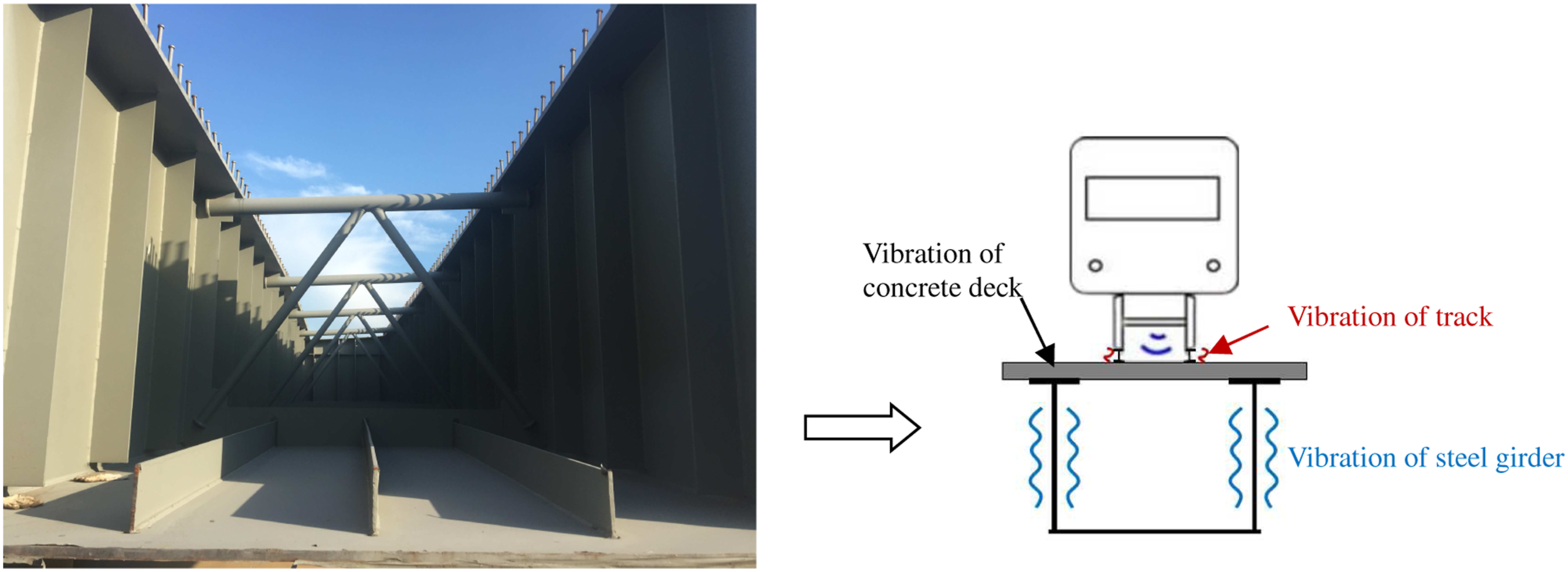
There have been several numerical and experimental investigations on vibration and noise of steel-concrete composite bridges. For example, Hou et al. 4 analyzed the dynamic characteristics of a simply supported composite beam and validated their findings experimentally. Zhang et al. 5 performed an experimental study on the dynamic responses of three steel-concrete composite beams under harmonic forces with a focus on the influence of the shear connection degree. Jiang et al. 6 compared the natural vibration frequencies of several steel-concrete composite box beams with different spans, degrees of shear connection, and boundary conditions using an improved finite beam element method. Allahyari et al. 7 measured the dynamic characteristics of unfilled steel-concrete composite decks with perfobond rib shear connectors and compared the natural frequency test results to finite element method (FEM) predictions. Malveiro et al. 8 reported a procedure for obtaining the physical properties of a dynamic model of a composite steel-concrete railway bridge using experimental tests. The frequency response function (FRF) characteristics were closely related to structural vibrations. For noise emanating from vibrating bridges, Li et al. 9 extended the statistical energy analysis method to predict a composite bridge consisted of double H-section steel longitudinal girders and a pre-stressed concrete deck cast on the steel girders. They reviewed the recent progress in studies on bridge-borne noise and concluded that the dominant noise frequencies from steel-concrete composite and steel bridges can be as high as several hundred Hz. 10 However, most previous researchers have focused on overall bridge vibration in the very low frequency range, but few on the local vibrations in the audible frequency range (>20 Hz).
The vibration and radiated noise associated with a bridge structure are closely related to the mass, stiffness, damping, and frequency response characteristic of the structure. 11 Thus, a series of vibration reduction methods have been presented for structural optimization design. These methods include increasing the mass, damping, and stiffness of the structure.12–14 A concrete bridge deck also provides an excellent noise reduction strategy for real applications. For instance, Saito et al. 15 and Lin et al. 16 performed hammering tests on a scale model of an I-shaped steel beam after casting a concrete deck. Vibration of the steel beam web was reduced substantially when the top flange was excited, but not when the web was excited. It is speculated that this is because the concrete deck can effectively reduce vibration energy propagation into the steel girder. However, for practical bridges, the influence of concrete deck on vibration transmission has not been quantitatively researched.
Damping has been investigated as an approach to reducing vibration and noise. Lee et al. 17 concluded that web excitation cannot always be assumed to increase the input impedance and thus effectively reduce sound radiation problems. Increasing structural damping may be a better way to reduce the web excitation response of a concrete box viaduct. Wilson and Kirschner 18 tested the vibration response of a steel-concrete composite girder bridge with a constrained layer damping (CLD). The vibration levels of the web and bottom plate were reduced by 9–12 dB in the frequency band above 50 Hz. Liu et al. 19 studied the vibration and noise reduction effects and mechanisms of a CLD applied to a high-speed railway steel-concrete composite bridge using the train-track-bridge coupling theory, modal strain energy method, and statistical energy analysis. The vibration velocity levels of the longitudinal and transverse beams were reduced by 10.5 dB and 6.1 dB, respectively, after installing the CLD. Although the method of applying damping materials works, it has disadvantages that include material aging characteristics, poor manual adjustment, or narrow effective frequency bands. An ideal design for bridge engineers is that the goal of vibration reduction can be achieved without adding external damping devices. Thus, the effect of structural damping on vibration transmission needs to be evaluated.
To understand the influence of stiffness, Han et al. 14 investigated the influences of the plate thickness and stiffeners on vibration attenuation of a concrete U-shaped girder via the modal superposition method. The results showed that structural noise could be reduced effectively by increasing the plate thickness and including transverse ribs. Alten and Flesch 1 evaluated the influence of rib position stiffening within the outer web and the position of the connection between the inner web and the bridge deck on bridge vibration. Bos 20 compared the effects of various plate thicknesses and beam heights on noise from steel bridge structures. Noise was reduced by 5–7 dB after adopting a series of measures. Liu et al. 21 found that the introduction of rib plates at the position of the maximum amplitude of the dominant mode shapes could reduce the sound pressure. Essentially, the vibration transmission rules of a certain structure can be largely influenced through adjusting structural stiffness (e.g., setting stiffener), while currently the effect of different stiffeners and transverse connections on vibration transmission of steel-concrete composite girders is rarely studied.
In view of the shortcomings of the existing research studies, the objective of this study is to investigate the dynamic properties of a channel steel-concrete girder in the mid- and high-frequency range (20–2000 Hz) that within the dominant frequency band for structural noise. A hammering test was performed to test the frequency response function of a full-scale segment of a practical channel steel girder. The experimental results were compared with those calculated using the finite element (FE) method. Then, the effects of damping and stiffness on vibration transmission were numerically compared. Finally, the influences of stiffeners and a concrete deck on the vibration energy were discussed, and corresponding quantitative results were presented.
Impact hammer tests
Outline of the test scheme
Hammering tests were used to test the vibration characteristics of a full-scale channel steel girder segment. The detailed dimensions of a specimen (before casting concrete deck) with a total length of 15.087 m are shown in Figure 2. The distance between the two webs (the left and right webs) was 2.9 m, and the left and right web heights were 2.202 m and 2.086 m, respectively. The distance between each pair of transverse connection components (TCCs) was 3.66 m, and three vertical web stiffeners (VWSs) were arranged equally on the web between every pair of TCCs. Three longitudinal bottom plate stiffeners (LBPSs) were arranged along the length direction of the specimen. The specimen was made from Q345qD steel. Hammering tests were performed on Sections I and II (with a spacing of 4.55 m). Each hammering force was a single impact induced by an impact hammer. During the test, the girder was simply supported on four temporary piers. Specimen dimensions (unit: mm): (a) plane view, (b) cross-sectional view, and (c) TCC.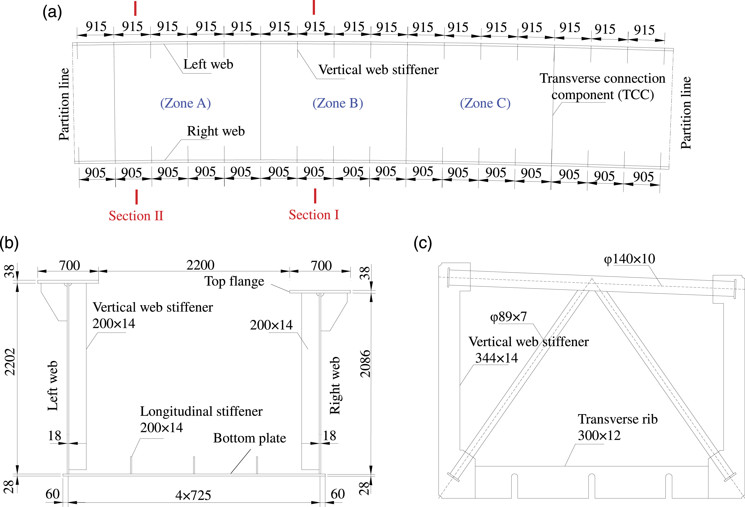
As shown in Figure 3, 10 accelerometers (type LC0108T) labeled A1 through A10 were placed in Section I, which were attached vertically to the web plate and the bottom plate. The accelerometers were not moved during the entire experiment. The accelerometers had a sensitivity of 500 mV/g and an effective frequency range of 0.35–5000 Hz. External excitations were induced on the plate surface using an impact hammer (type LC1303B) with a measurement range of 100 kN, sensitivity of 0.0447 mV/N, and mass of 2.3 kg. Each hammering test was performed more than five times. The average of the values from all hammering tests was taken as the test result to reduce error. Schematic of measurement points A1–A10 from Section I. Note: hammering locations a, b, and c are used in both Section I and Section II.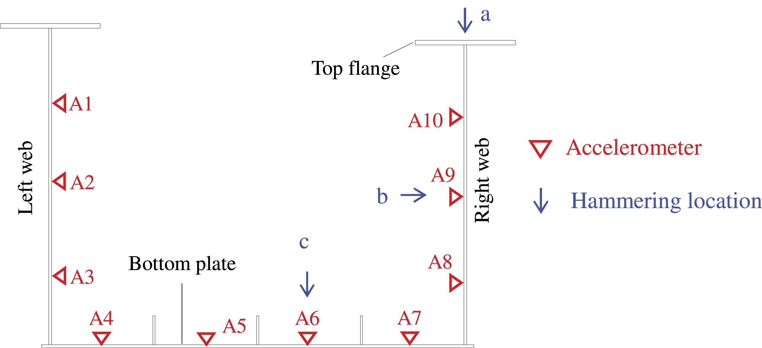
The authors were not permitted to test the case after a concrete deck installation. Thus, the goals of the impact hammer tests in this study were to: (1) provide accurate information about the vibration transmission characteristics in the channel steel girder and (2) validate the FE models using the measured dynamic parameters. Since it was not able to conduct a strict and sufficient measurement after concrete deck installation, the validated FE models could then be employed for further vibration analysis. The measurement cases considered during these tests were as follows: (1) Hammering the top flanges of Sections I and II, abbreviated as Cases I-a and II-a, respectively. (2) Hammering the right webs of Sections I and II, abbreviated as Cases I-b and II-b, respectively. (3) Hammering the bottom plates of Sections I and II, abbreviated as Cases I-c and II-c, respectively.
Note that the accelerometers were fixed at Section I, while the hammering locations were arranged in both Sections I and II. The tests conducted in two sections were used to explore the vibration transmission characteristics of the channel steel girder.
Test results
During the tests, vibrations were evaluated using an acceleration FRF that addressed the ratio of the cross-spectral densities of the excitation force x and the response signal y (i.e., S xy ) to the auto-spectral density of x (i.e., S xx ). 11 The FRF curve is presented in the one-third octave band spectrum using an acceleration reference value of 1×10⁻⁶ (m/s2)/N. Since the frequency range discussed in this paper is wide and structural noise is generally evaluated via broadband spectrum, the one-third octave band spectrum is adopted in this paper rather than the narrowband spectrum.
In this paper, a hammer is used to excite the specimen at different positions. If the input forces and therefore energy are high, the global and local vibrations can be excited. As it has sufficient force to generate adequate vibration level for the measurement, the measured acceleration FRFs are valid. In addition, to measure the FRF quality, the coherence function is checked during data processing.
FRFs for Case I-a: (a) right web, (b) bottom plate, and (c) left web.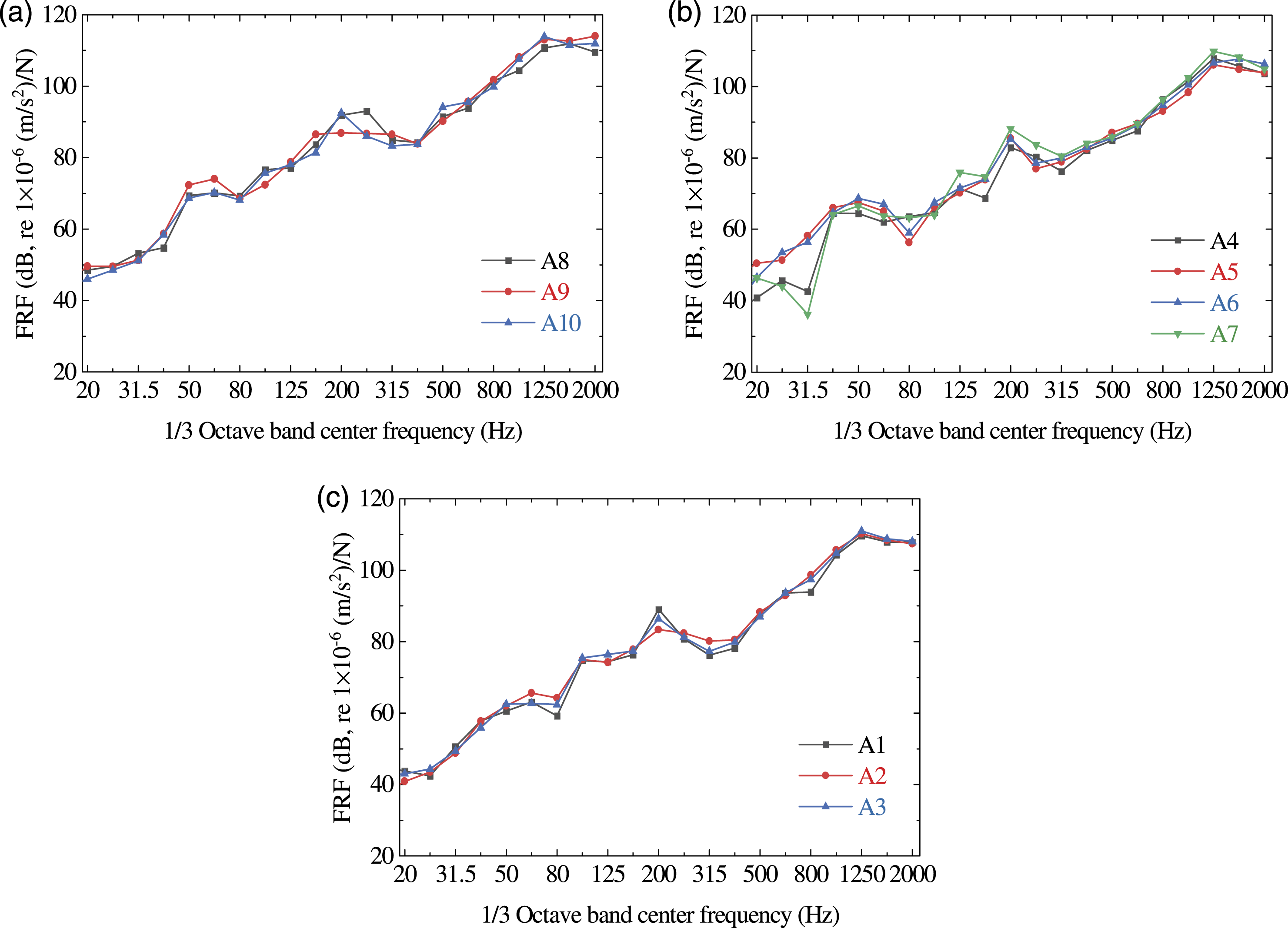
Figure 4(a)–(c) show the right web, bottom plate, and left web FRFs arranged from large to small. The bottom plate and left web FRFs are reduced by 4.3 dB and 5.8 dB on average per frequency band relative to the right web FRFs. This is attributed to the damping effect of the structure and the vibration attenuation effect on the coupling boundaries (i.e., the junctions among different plates). From Figure 4(b), A4 and A7 on the bottom plate exhibit smaller FRFs than A5 and A6 in the frequency band below 40 Hz (e.g., 25 Hz and 31.5 Hz). This is because low frequency vibrations are affected mainly by boundary constraints and the overall plate stiffness. A4 and A7 are arranged on the bottom plate at the junction with the web plate. Because the restraint effect is greater and the rigidity is higher, the vibrations are smaller at low frequencies. However, in the high frequency range, this restraint effect is not obvious.
In order to describe the differences in the vibration characteristics of the different sections, DFRF was calculated by subtracting Case I-a from Case II-a. The results are shown in Figure 5. The center line of the strip is the average value of DFRF at each measurement point in Section I (sensor arrangement section) in both cases. The upper and lower envelopes represent the maximum and minimum DFRF values, respectively. DFRF is always less than zero except within certain frequency bands. For positive values at certain frequency bands (such as 80 Hz), they are associated with the vibration resonance of structural plates. This indicates that the vibration attenuates as the distance between the excitation and measurement points increases. In addition, there is no significant difference between the center line and envelope of each strip. This shows that the Case II-a and Case I-a FRFs of different measurement points on each plate have the similar variation characteristics. DFRF between Cases II-a and I-a: (a) right web, (b) bottom plate, and (c) left web.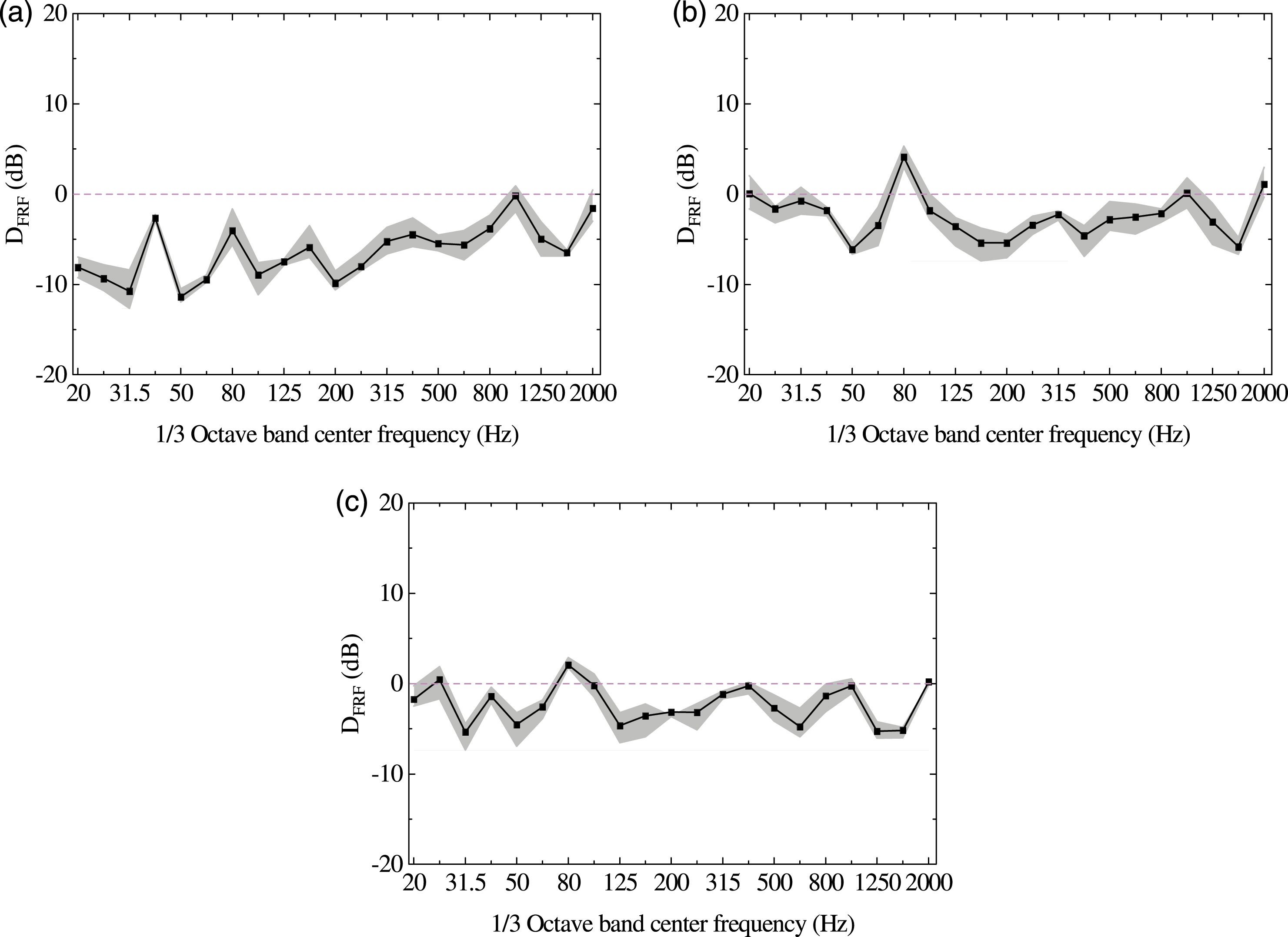
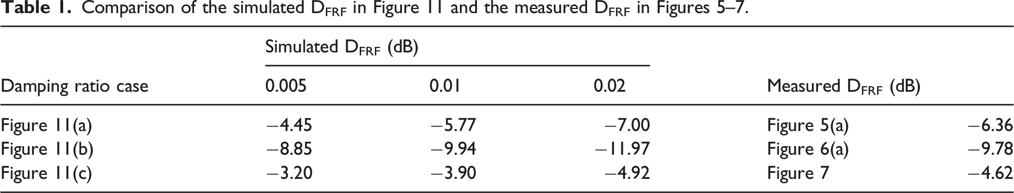
In the 20–2000 Hz center frequency range, the right web, bottom plate, and left web DFRF values decrease by 6.36 dB, 2.43 dB, and 2.32 dB, respectively, on average. It is clear that the DFRF values of different plates exhibit substantial differences. This is influenced by two factors: the “distance” and “transmission path”. Specifically, the effect of “distance” is reflected mainly via energy dissipation caused by material damping. The “transmission path” is related to stiffeners (e.g., geometric dimension and directionality), the coupling boundary (i.e., the junctions among different plates), etc. Its effect is reflected mainly via energy dissipation caused by the coupling boundary and stiffeners. Test results clearly show that the transmission path effect is more important than the distance effect regarding vibration variation. Specifically, the right web is most affected by the effect of “transmission path,” while the left web is most affected by the effect of “distance”. Therefore, the DFRF of the right web is the largest, while the DFRF of the left web is the smallest.
FRFs for Cases II-b and I-b: (a) right web and (b) bottom plate.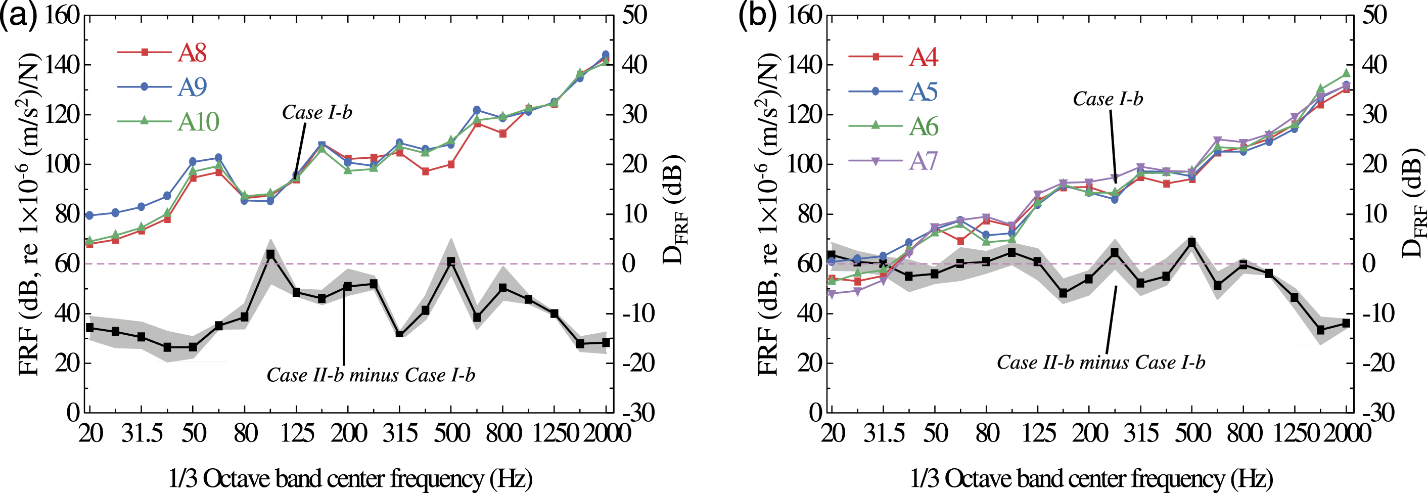
As in Figure 6, vibration attenuation in Cases II-b and I-b corresponds to both the distance effect and transmission path effect. The DFRF values of the right web and bottom plate decrease by 9.78 dB and 2.21 dB, respectively, on average in each frequency band.
Bottom plate FRFs for Cases II-c and I-c.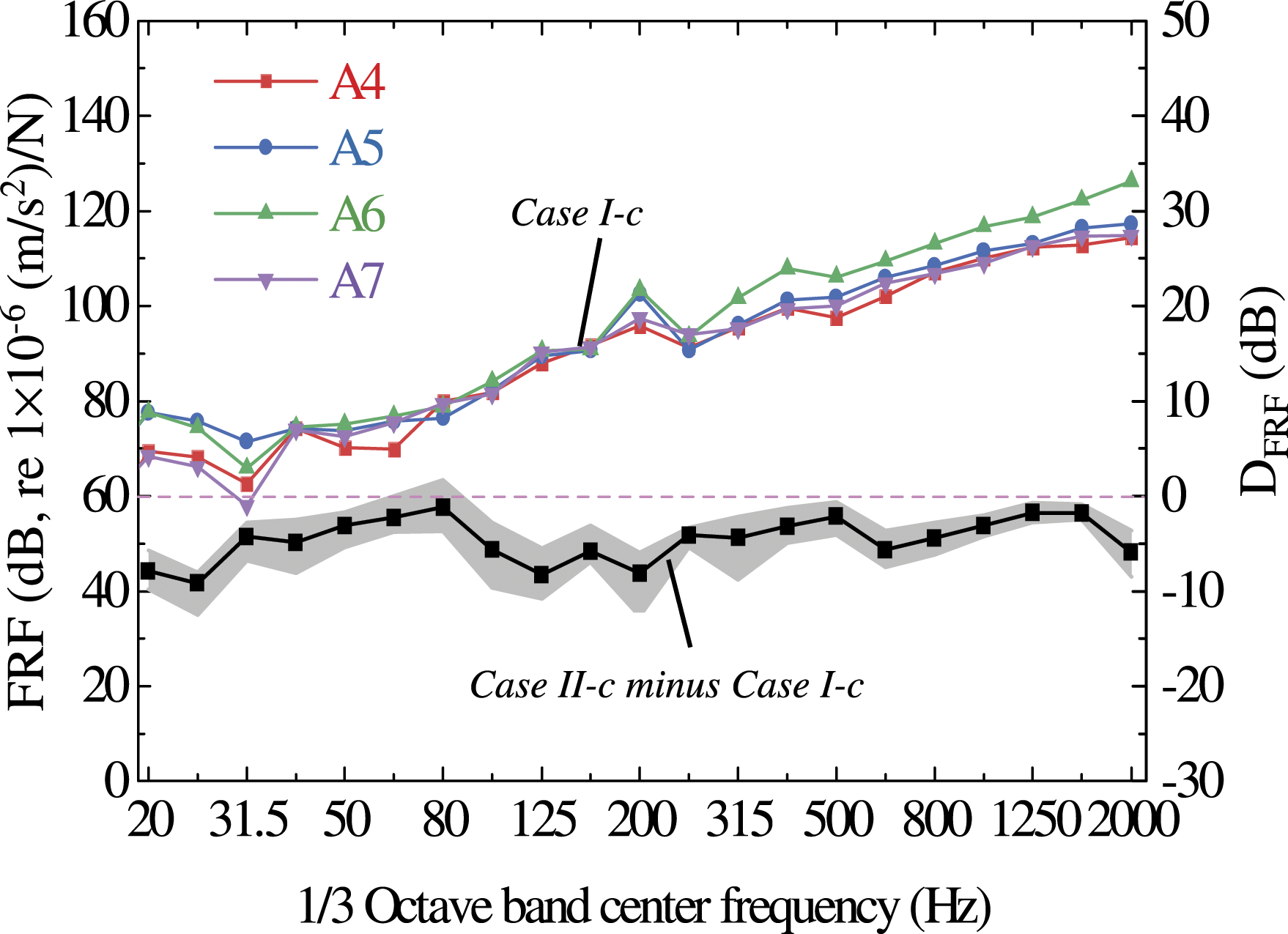
Finite element modeling
In this section, the FE model is established and its validity is verified using a hammering test. The FE model of the specimen was created using the commercial software ANSYS. Here, the SHELL63 element was used for the steel plate and the BEAM188 element was used for the transverse connection components (TCCs). The maximum element dimension in the model was limited to 0.05 m. The model contained 68,581 elements and 68,950 nodes. The Young’s modulus, density, and Poisson’s ratio of steel were assumed to be 210 GPa, 7850 kg/m3, and 0.3, respectively. The simply supported boundary condition consisted with the test scheme was adopted. Herein, a unit harmonic force was applied to the model and the calculated results were obtained by harmonic response analysis. The damping ratio of the specimen is estimated as 0.015, and detailed information can be found in Section The roles of structural damping and stiffeners.
Figure 8 plots the first seven vibration mode shapes and their corresponding frequencies of the channel steel girder. As a general rule, the global vibration mode of a bridge is taken as the mode having bending motion along the span with no significant deformation on the cross-section. In the local vibration mode, there is a bending mode in the cross-section of the bridge. It can be seen that the first two orders of vibration mainly represent global vibration of the channel steel girder. Local vibrations of the web and bottom plates tend to be more substantial at higher-order modes. Obviously, the high-order modes contribute more to the mid- and high-frequency vibrations than that of the low-order modes. The FE model and its free vibration characteristics of the channel steel girder.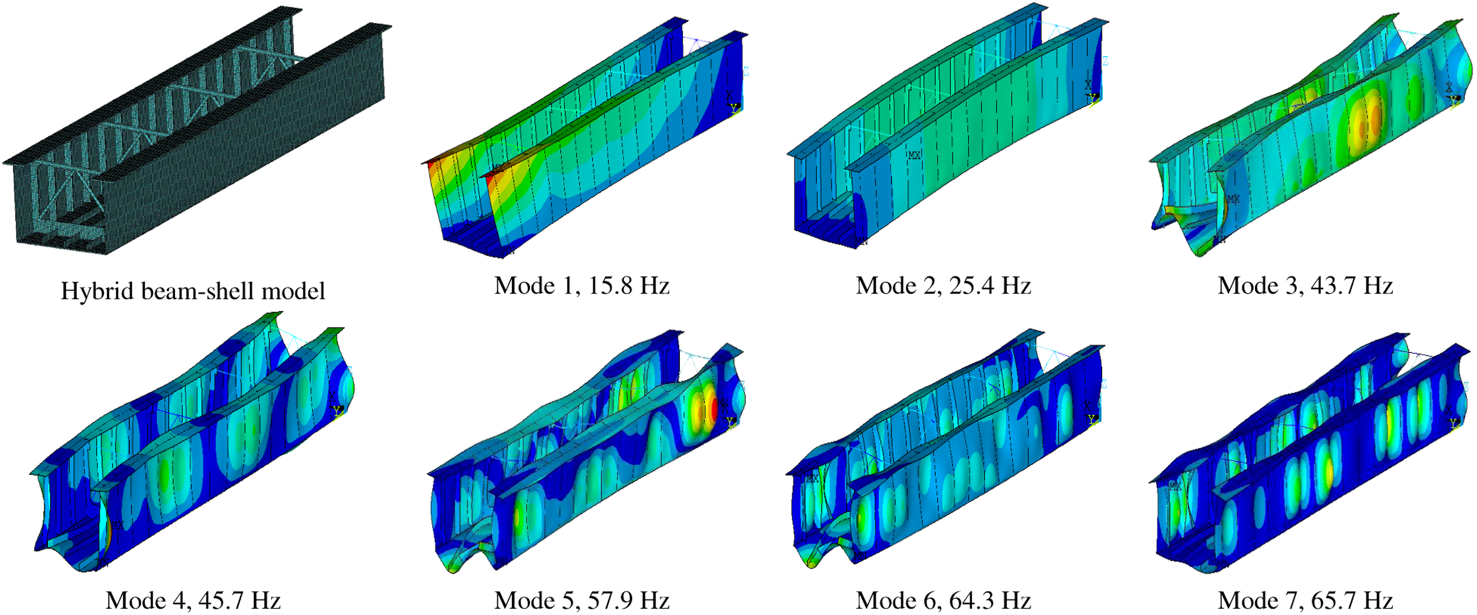
Figure 9 compares the measured and calculated right web, bottom plate, and left web FRFs, respectively, for Case I-a. The measured FRFs represent the average of all measurement points. The upper and lower envelopes of the black strip represent the measured maximum and minimum values, respectively. In general, the FRFs are predicted reasonably in the considered center frequency band (20–2000 Hz), and the frequency dependence exhibits good agreement with the measured results. Therefore, the FE method can determine the structural vibrations reliably. Since the frequency range discussed in this paper is wide, it is not possible to attain a perfect coincide in every frequency band between simulated results and measured data. The acceptable simulation error is generally around 3 dB in most bands in the frequency range considered.9,11,19,21 In this paper, because the structural damping parameters and actual boundaries cannot be considered accurately, there are inevitable differences between the numerical model and the real structure. This leads to deviation between the simulated and measured results. The average differences between the measured and calculated right web, bottom plate, and left web FRFs are 3.7 dB, 2.6 dB, and 1.0 dB, respectively. Comparison of measured and simulated FRFs (Case I-a): (a) right web, (b) bottom plate, and (c) left web.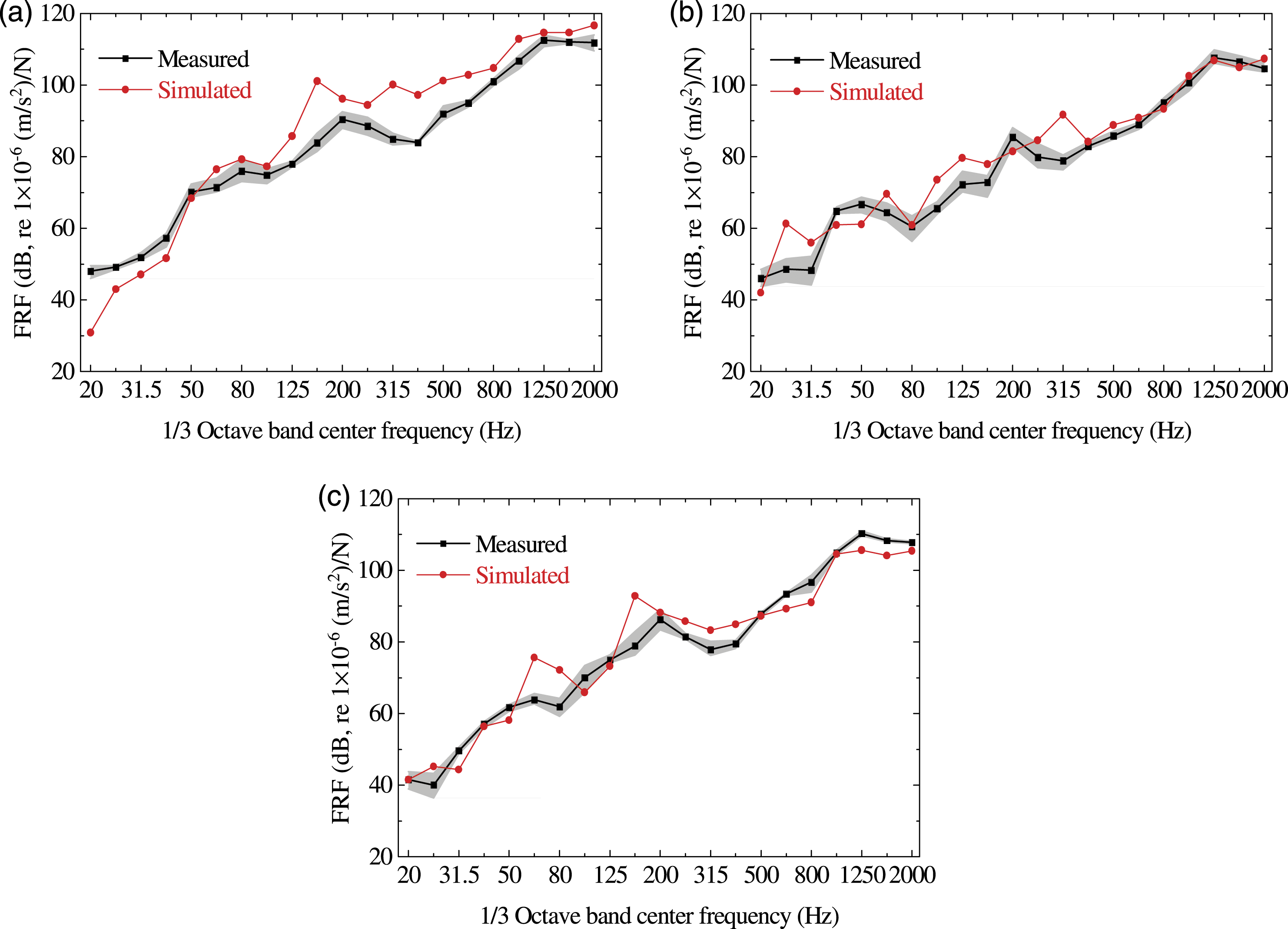
Figure 10 compares the measured and calculated DFRF values for each plate. The measured and calculated DFRF values show good agreement with respect to magnitude. The DFRF in Figure 10(b) fluctuates more with the frequency than those in Figure 10(a) and (c). This is thought to be related to two factors. First, unlike in Figure 10(a), the hammering point and accelerators in Figure 10(b) are located on the same plate. When the excitation position is close to the sensor position, the vibration response is very sensitive to the excitation position. Second, the directions of stiffeners on bottom plate and right web are different. For the bottom plate stiffener (Figure 10(c)), the vibration propagation direction is along the stiffener direction; while for the right web stiffener (Figure 10(b)), the vibration propagation direction is perpendicular to the stiffener direction. Comparison of measured and simulated DFRF values: (a) right web, Case II-a minus Case I-a; (b) right web, Case II-b minus Case I-b; and (c) bottom plate, Case II-c minus Case I-c.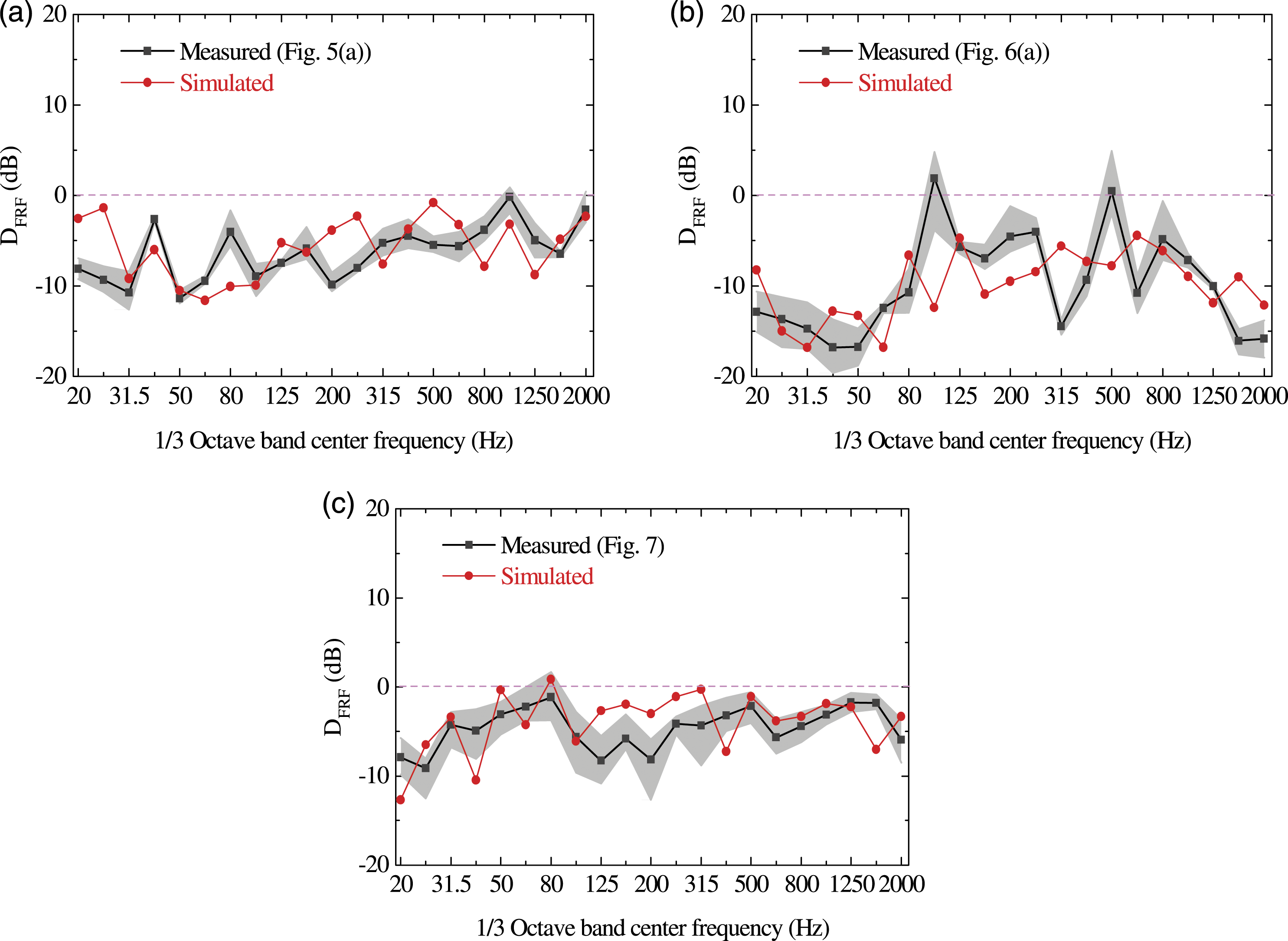
Parametric studies based on numerical analysis
In this section, the vibration behavior of the channel steel girder is further examined to determine the influences of damping, stiffeners, and a concrete deck. The purpose of this is to provide a theoretical basis for optimizing various parameters. Then, one can conduct a sufficient topological optimization procedure according to the specific vibration reduction requirements.
The influences of damping and stiffeners on the DFRF are evaluated. In addition, the vibration energy of each plate is numerically analyzed before and after concrete deck installation because the test comparison cannot be implemented. The vibration energy curve is presented in the one-third octave band spectrum, with a reference vibration energy value of 1×10⁻¹² (m4/s2)/N.
The roles of structural damping and stiffeners
Figure 11 shows the vibration attenuation for various cases with damping ratios of 0.005, 0.01, and 0.02, respectively. Clearly, DFRF has a consistent variation law with different damping. Because the DFRF decreases across all frequency bands, vibration can be reduced stably by increasing damping. The influence of structural damping on DFRF: (a) right web, Case II-a minus Case I-a; (b) right web, Case II-b minus Case I-b; and (c) bottom plate, Case II-c minus Case I-c.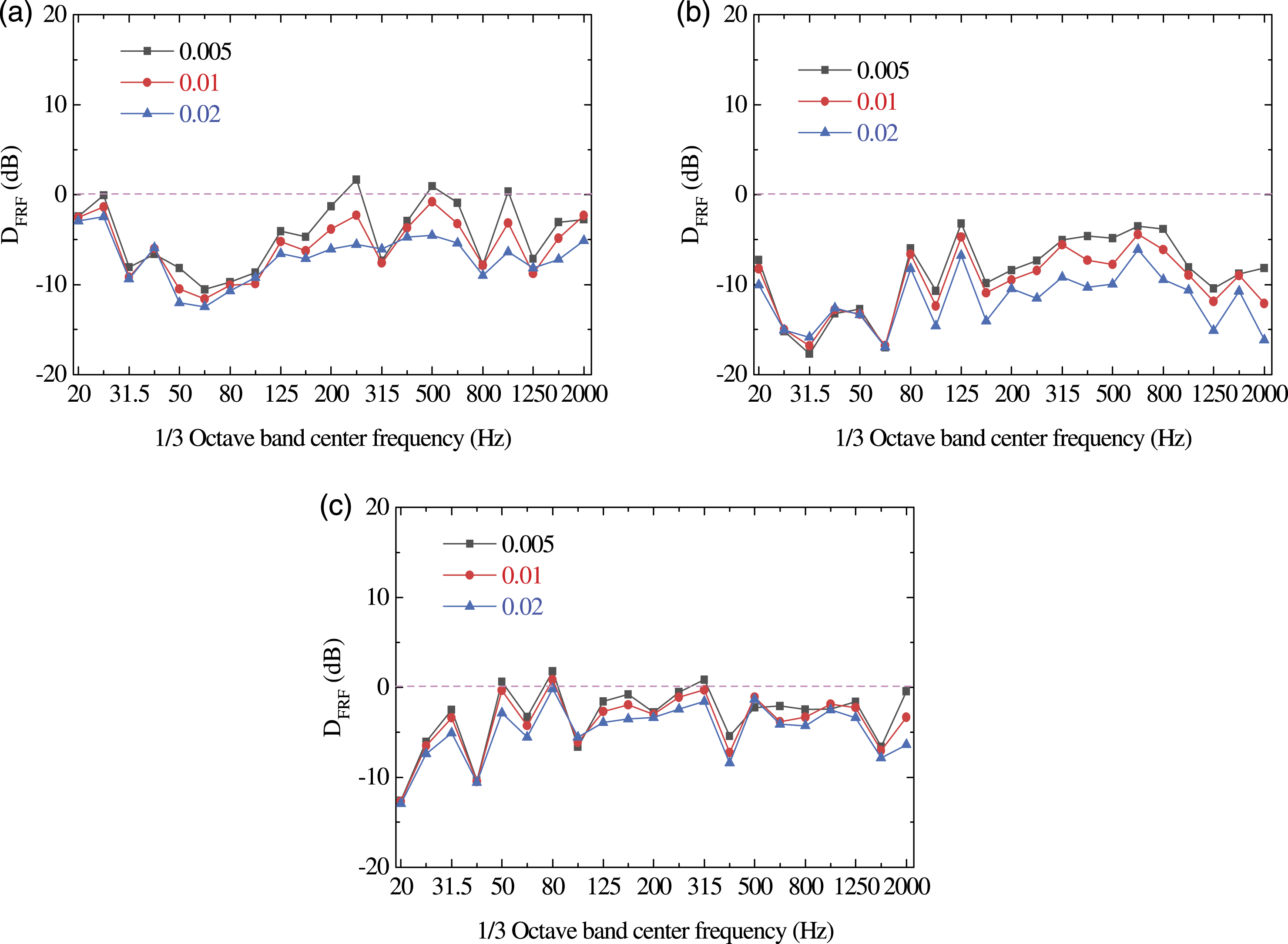
In order to investigate the influence of the vertical web stiffener (VWS) and longitudinal bottom plate stiffener (LBPS) on structural vibration attenuation, the DFRF values of ribbed and un-ribbed models were calculated, and then the difference in D
FRF
was calculated (see Figure 12). Taking the black curve as an example, DFRF values with and without VWS are calculated separately for Cases I-a and II-a. The difference in D
FRF
is the “DFRF with VWS” minus the “DFRF without VWS”, and is marked “Right-web, Case II-a minus Case I-a (VWS)” in the figure. Note that in the un-ribbed models, the other parameters remained unchanged. Variation in DFRF under various VWS or LBPS configurations.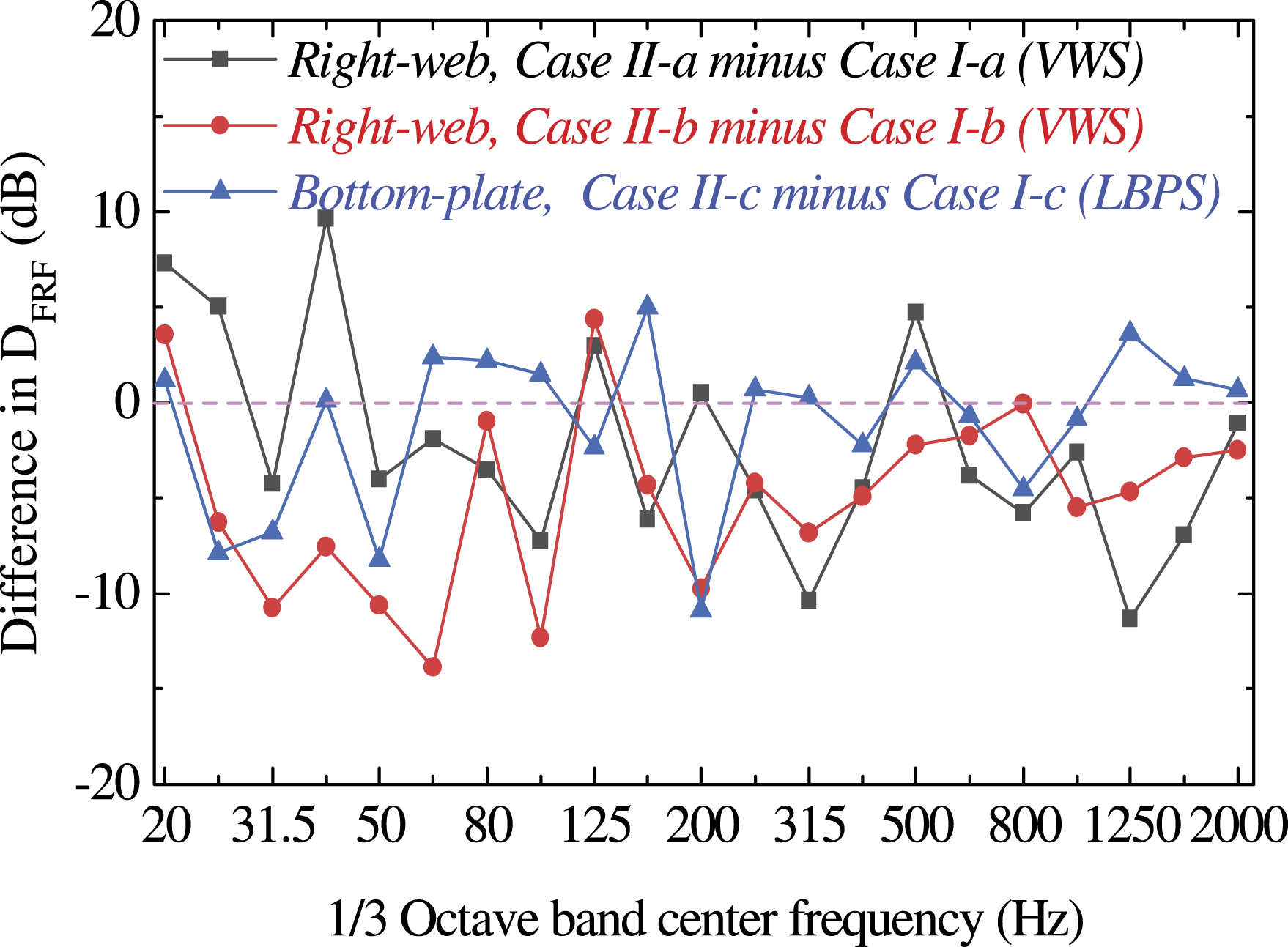
The results in Figure 12 indicate that the difference in D FRF fluctuates around zero when the stiffener changes (reflecting a change in plate stiffness) and exhibits some irregularity. According to the calculation, the average difference in D FRF for “Right web, Case II-a minus Case I-a (VWS)” is −2.29 dB; the average difference in D FRF for “Right web, Case II-b minus Case I-b (VWS)” is −4.97 dB; and the average difference in DFRF for “Bottom plate, Case II-c minus Case I-c (LBPS)” is −1.13 dB. The influence of stiffeners on the average difference in D FRF is greater than that of damping; indicating that the plate stiffness has a larger effect on structural vibration. Furthermore, VWSs can prevent vibration transmission more effectively than LBPSs. It is noted in this case the vibration transmission direction (from Section II to Section I) is perpendicular to the stiffener direction (VWS).
Comparison of vibration transmissions
The influences of (a) VWS, (b) LBPS, and (c) TCC systems on the VE before CD installation. The schematic in each figure panel shows the excitation location (purple arrow) and response location (hidden plate).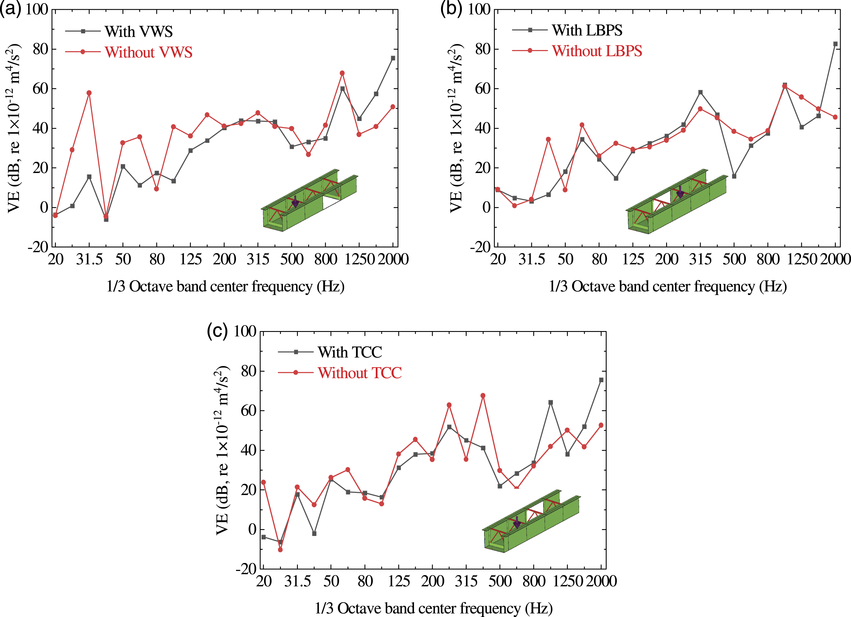
As depicted in Figure 13, the stiffening system exhibits strong vibration reduction effects in the low and middle frequency band (<500 Hz). However, the VE with stiffeners is larger than that without stiffeners in a few high frequency bands. This is presumably caused by a shift in the resonant frequency of corresponding structural plates. The average VWS, LBPS, and TCC VE variations are −5.54 dB, −1.37 dB, and −1.96 dB, respectively, compared to corresponding cases without stiffeners. Thus, the stiffening system has particular significance in reducing overall structural vibration. Of the approaches considered, VWS has the most prominent influence in vibration reduction.
Figure 14 plots the first seven vibration mode shapes and their corresponding frequencies of the channel steel-concrete composite girder. After installing the CD, the frequency of corresponding free vibration decreases. The vibration of CD plays a prominent role in the first seven-order of vibration, while the local vibration of the web and bottom plates is relatively smaller than that of the channel steel girder. The FE model and its free vibration characteristics of the channel steel-concrete composite girder.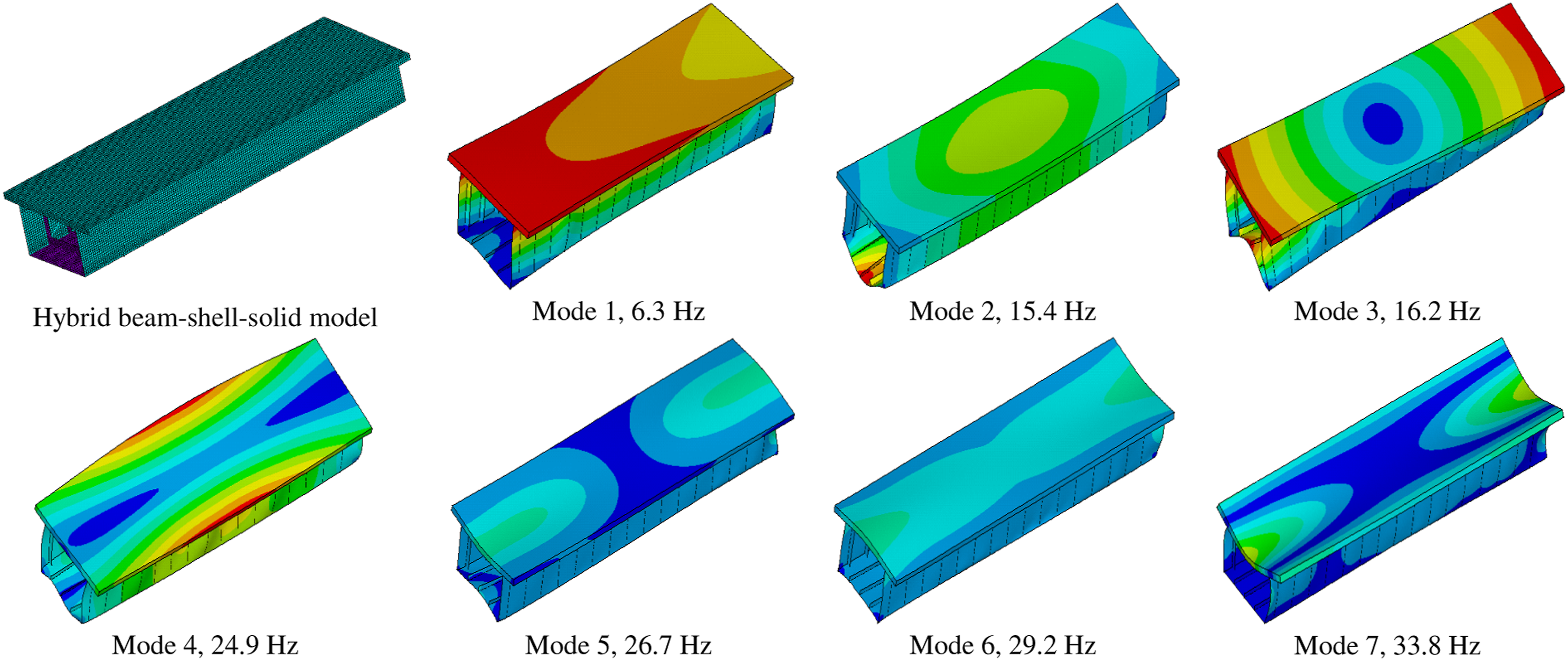
The influence of the CD on the VEs of various plates located on the channel steel girder is compared in Figure 15. Note that the CD is not shown in each figure panel for clear demonstration. Except at a few frequencies, the CD has a significant impact on vibration reduction. For frequency points with opposite regularity (such as 31.5 Hz), this is presumably related to the shift of resonant frequency after the installation of CD. After installing the CD, the VEs of the right web, the bottom plate, and the left web decrease by 14.37 dB, 11.82 dB, and 10.83 dB on average, respectively. The influence of the CD on the VE decreases slightly as the transmission distance (from the right web to the left web) increases. The influence of CD installation on the VE: (a) right web, (b) bottom plate, and (c) left web. The schematic in each figure shows the excitation (purple arrow) and response (hidden plate) locations.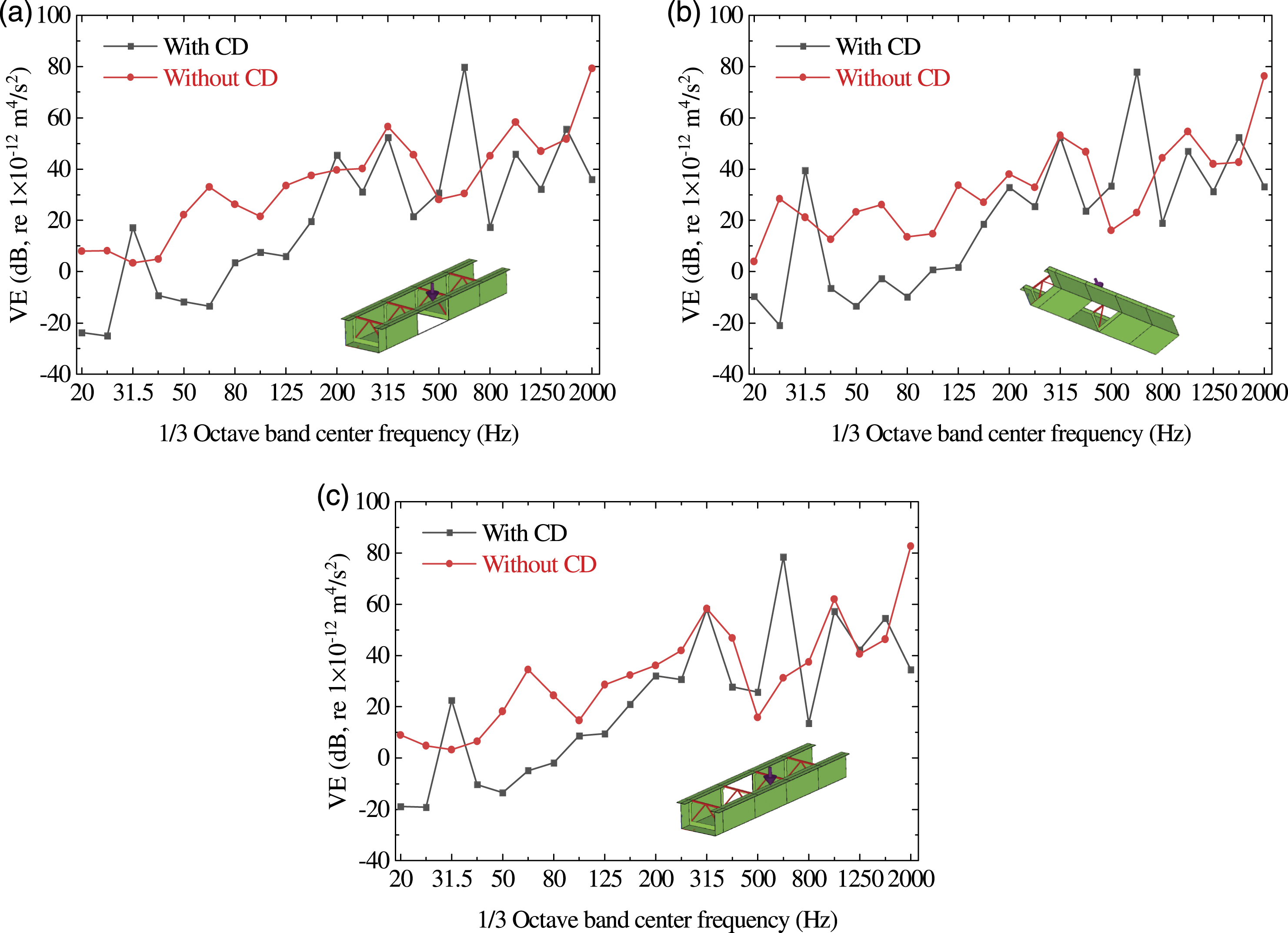
Conclusions
In this paper, the vibration characteristics of a full-scale segment of a practical channel steel girder in the center frequency range of 20–2000 Hz were investigated via hammering tests and numerical simulations. Based on FE modeling, the effects of damping and stiffeners on the channel steel girder vibration response and transmission were discussed. Finally, the influence of the concrete deck on the vibration energy was numerically studied. The main conclusions can be summarized as follows: (1) The vibration response of a certain position is not only related to the distance from the position to the excitation source but is also affected by the constraints on the position and the local bending stiffness. In general, the stronger the constraints and the larger the bending stiffness, the smaller the vibrations. This is observed mainly under low-frequency conditions. (2) When different positions are excited, both the effects of distance and transmission path influence vibration variation. In a channel steel girder, the transmission path corresponding to the energy dissipation is more important than the distance. For the former, it is caused by the coupling boundary and stiffeners; for the latter, it refers to the material damping. (3) The FRFs are predicted reasonably in the considered center frequency band (20–2000 Hz) via the FE method. The frequency dependence shows good agreement with the measured results. The average right web, bottom plate, and left web errors are 3.7 dB, 2.6 dB, and 1.0 dB, respectively. (4) Structural vibration can be reduced by increasing the damping and stiffness. Stiffness changes (e.g., installing stiffeners) have larger effects on overall structural vibration but may lead to vibration increases in certain frequency bands. In contrast, increasing the damping ratio can reduce the structural vibration stably. (5) Structural vibration can be reduced by installing a concrete deck and stiffening system. The concrete deck has the largest vibration reduction effect, and can reduce structural vibration energy by more than 10 dB. In the stiffening system, the vibration reduction effect of the VWS is better than those of the LBPS and TCC since the vibration transmission direction is perpendicular to the VWS stiffener direction.
Footnotes
Declaration of conflicting interests
The author(s) declare no potential conflicts of interest with respect to the research, authorship, or publication of this article.
Funding
The author(s) disclose receipt of the following financial support for the research, authorship, or publication of this article. This work was supported by the National Natural Science Foundation of China (grant numbers 51778534 and 51978580) and the Sichuan Science and Technology Program (grant number 2020JDJQ0078).