
Abstract
The underwater anechoic coating with local resonant units is an effective method to achieve low-frequency sound absorption. However, the structure obtained in this way is not satisfactory in the sound absorption effect of mid-high frequency bands. Capitalizing on the impedance gradient characteristics of functionally graded materials (FGMs) can improve the impedance matching between the structure and the medium, and enhance the dissipation of sound waves inside the structure. Based on these, we propose an underwater acoustic structure, which can improve and obtain low-frequency and broadband sound absorption performance by embedding local resonators into FGMs. To reveal the sound-absorbing mechanism and further optimize the low-frequency absorption performance of the structure, we conduct quantitative analyses on the parameters of FGMs, the materials and forms of resonators. The results indicate that by appropriately adjusting the studied parameters, different low-frequency sound-absorbing peak can be obtained and the absorption effects are also further improved.
Keywords
Introduction
It is well known, the anechoic coating with good sound absorption performance is essential for the safe navigation of underwater vehicles. 1 Meanwhile, the design of the anechoic coating with good sound absorption performance should not only satisfy the good impedance matching characteristics of the acoustic structure and the contact fluid medium but also ensure the sound wave energy entering the sound absorption structure be dissipated as much as possible. 2 However, no matter how strong the sound absorption ability of the material is, the absorption of the designed anechoic coating will be weak if sound waves are significantly reflected at the fluid-structure interface. Thus, improving impedance matching characteristics between the absorber and the fluid medium is key to enhance the sound-absorbing capacity, and functionally graded materials (FGMs) have attracted widespread attention as a material with variable impedance gradient.
FGMs are a new type of composite materials in which two or more materials are composited and the material properties are gradient changed along a certain dimension of the structure in space. 3 In recent years, FGMs have been widely used in the field of machine design and manufacturing as they have strong designability and easy to realize multi-physics coupling.4–8 Simultaneously, due to the excellent acoustic performance of FGMs, they are widely concerned by scholars employed as sound-absorbing materials.9–13
When considering the good impedance matching characteristics of FGMs, FGMs can be widely used in the design of the underwater anechoic coating. Initially, Kang and Bolton 14 proposed a porous elastic wedge and foam layer with spatial gradient characteristics as FGMs, and they found that broadband absorption can be achieved. Aksoy et al. 15 established a calculation model by using the space–time discontinuous Galerkin method and verified the correctness of the analytical mode to analyze the wave propagation characteristics of FGMs. Climente et al. 16 established a gradient acoustic structure in which the surface impedance of the gradient structure perfectly matches the acoustic impedance of the medium. The results showed that the structure improve the impedance matching characteristics of the sound-structure coupling interface and achieve a good sound absorption effect at 1 kHz–3 kHz. Zhang et al. 17 designed FGMs that can be used as an underwater acoustic coating layer and studied the underwater acoustic behaviors in the low-mid frequency range. The conclusion presented that, as FGMs can be designed easily, FGMs with acoustic properties required for practical applications can be obtained by changing factors such as material properties and volume fraction. Shi et al. 18 proposed an underwater functionally gradient anechoic coating structure with cavities and established a numerical calculation model by gradient finite element method (G-FEM). The research provided a new design idea for widening the sound absorption frequency band of underwater acoustic structures. Feng et al. 19 proposed composite structures with different gradient impedances, and numerical and experimental methods are used to study the influence of impedance gradient form and discrete layering method on the acoustic performance of the structure. It is demonstrated that the gradient-index structure can achieve good absorption effect at low-frequency, and the equivalent thickness layering method is superior to the equivalent impedance layering method. Liu et al. 20 discussed the underwater acoustic performance of impedance gradient structure by using experimental methods under vertical and oblique incident conditions, and provided theoretical support for the application of FGMs in underwater sound absorption.
Although impedance gradient materials can be used to improve the impedance matching characteristics between the structure and the contact medium, so that the structure can obtain broadband sound absorption effect in the medium and high frequency band. However, since FGMs belong to a kind of viscoelastic composite material, the sound absorption mechanism is the same as the energy dissipation mechanism of homogeneous viscoelastic materials. FGMs, as viscoelastic composite materials, show very low efficiency for attenuating the low-frequency sound absorption. In other words, FGMs are also unable to obtain good low-frequency sound absorption effect with small structure dimensions. 21
Utilizing the resonance characteristics 22 of the structure is an effective means to solve the poor low-frequency acoustic performance of the anechoic coating. In recent years, the locally resonant acoustic metamaterial (LRAM) developed based on the local resonance mechanism have been widely studied by researchers due to their special physical properties.23–27 Additionally, with the development of underwater sonar detection and recognition technology, 28 in consideration of the low-frequency sound absorption characteristics of LRAM, LRAM is increasingly used in the design and research of the anechoic coating for underwater vehicles.29–34 However, the shortage of the sound absorber with the local resonance mechanism is that the absorption effect is only strong in the resonance peak frequency and in narrow range near it, and the sound absorption is weak at the non-resonant peak, especially in high frequency bands.35,36
To the authors’ knowledge, there are few related studies on impedance gradient structures and the locally resonance coupling calculation and their combined effect on acoustic performance of underwater anechoic coatings so far. Herein, we propose an underwater acoustic structure, in which local resonators (LRs) composed of steel cylinder and rubber coating are embedded into FGMs. The purpose is to couple the advantages of the FGMs and local resonance mechanism in sound absorption. The acoustic calculation model of the structure is established by using G-FEM. The transfer matrix method (TMM) calculation results verify the correctness of G-FEM in this study. In addition, the gradient change form in the thickness direction, the material, number, structural form and the filling rate of the resonator, and the material parameters of FGMs that affect the sound absorption effect of the structure are studied, and the sound absorption mechanism is also analyzed.
Geometric model and methodology
Geometric model
The overall schematic diagram of the designed underwater anechoic coating is shown in Figure 1, and it has four different sections: gradient materials layer, rubber coating layer, steel resonator, and steel plate backing. The rubber coating and the steel resonator constitute the local resonance unit which is located in the gradient matrix layer. Also, the local resonance unit is periodically arranged along directions of x, y and it is assumed to be extended infinitely in the x and y directions. Figure 2(a) and (b), respectively, show the basic 3D cuboid structural unit and its section views. The lattice constant of this periodic acoustic structure is a. The radius and height of the resonator are r1 and h1, respectively. The radius and height of the rubber coating are r2 and h2, respectively. The height of the gradient materials layer is h. The thickness of the steel plate backing is hs. The overall view of the underwater anechoic coating includes gradient materials layer, steel backing, and steel cylindrical resonator with rubber coating. (a) The basic 3D cuboid unit. (b) The z-x section views of the unit.
Methodology
In this study, the G-FEM is used to numerically simulate the acoustic performance of the designed structure. Different from the conventional finite element method, G-FEM considers the change of material properties in the gradient direction of the structure and establishes a gradient mesh element based on this. For FGMs, the G-FEM can accurately simulate the variation of material properties in FGMs,
37
and then obtain the accurate variation of acoustic properties. Hypothetically, the water domain satisfies the ideal conditions of uniformity and incompressibility, and the wave equation of the sound wave can be expressed

After a series of complex mathematical derivation, the finite element equation can be expressed as

Simultaneously, for solid structure parts, the gradient finite element equation is written as

According to equations (2) and (3), the discretized form of the acoustic-structure coupling equation for a periodic unit can be written as

In this paper, a two-phase FGM as the gradient materials layer of the proposed structure is designed, which is synthesized by two different viscoelastic materials according to the certain technological process, so that the material properties change continuously along the z direction.
38
According to the mixing rules, the functional parameters of the established materials can be written as
39


Firstly, a numerical calculation unit model is established by COMSOL Multiphysics (V5.6), as shown in Figure 3, in which a steel cylinder is wrapped in the silicon rubber coating layer, and they are embedded in the matrix of the gradient materials layer and attached with a steel backing plate. Set a normal incidence plane wave from the fluid domain to act on the unit cell. Meanwhile, it is assumed that there is a semi-infinite air domain behind the steel plate backing. In addition to the fluid domain, which is set as the pressure acoustic module, other units in the structure are set as the solid mechanics module. Then, the material parameters of each section are set. Wherein the matrix part is the FGMs, its material parameters change with the gradient direction z in accordance with the previous analysis, so it is set as variable parameters. For three-dimensional model studied in this paper, it is necessary to set the boundary conditions correctly for each surface through which the sound wave passes. It includes continuity boundary conditions, acoustic-structure boundary conditions, and total reflection boundary conditions shown in Figure 3. Allowing for the researched structure is uniformly and periodically distributed in the underwater anechoic coating, Since the unit structure under study is periodically distributed in the anechoic coating, the expression for the spatial periodic function χ (displacement, acoustic pressure) can be determined by using Bloch’s theorem: Schematic diagram of numerical simulation calculation model.

The sound absorption effect of the design structure in this paper can be expressed by the sound absorption coefficient α, written as

Verification of numerical method
The physical characteristics of the proposed structure.
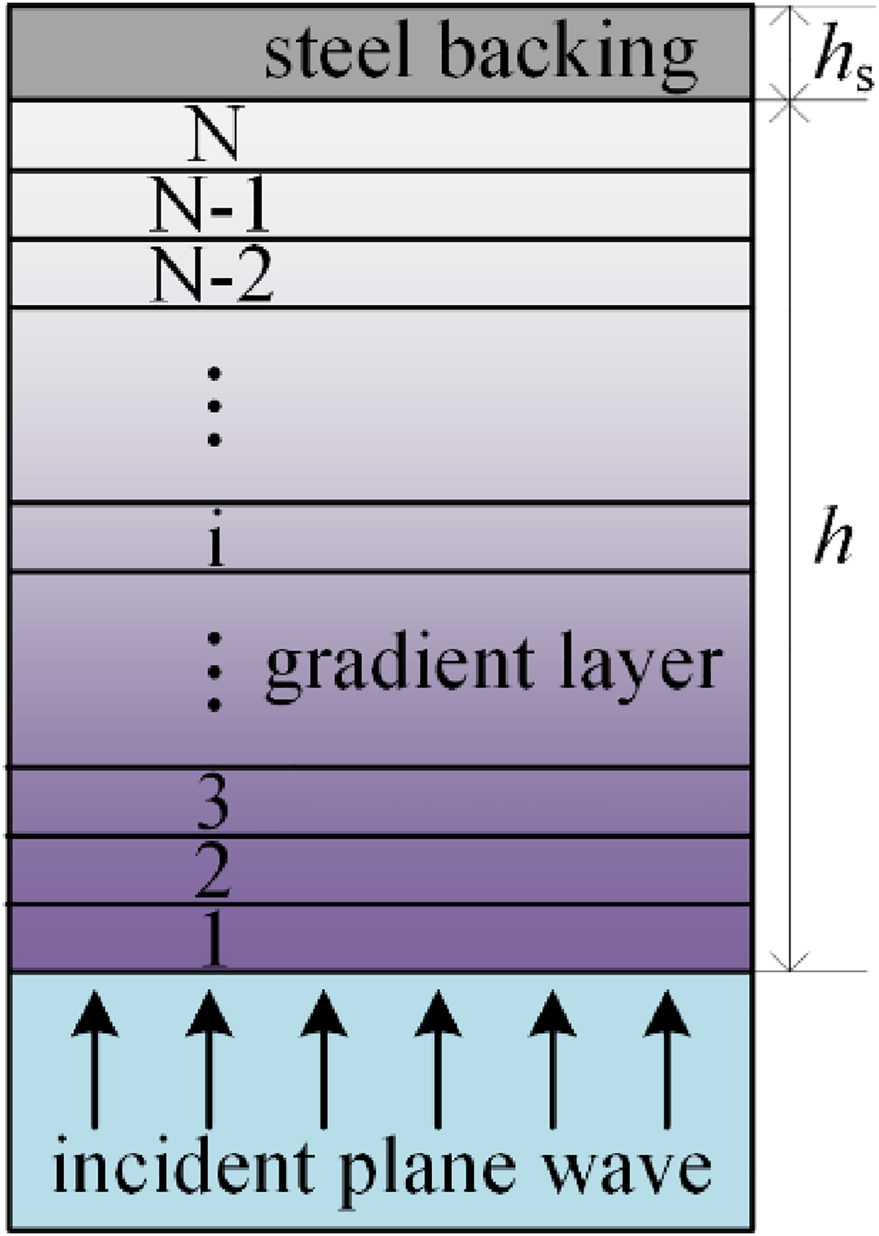
Schematic diagram of the transfer matrix method calculation model.
The sound absorption coefficients of the structure without LRs calculated by the numerical simulation method, which is based on the G-FEM, and by analytical method of the TMM under different gradient indices is shown in Figure 5. The results show that the sound absorption coefficients of the underwater anechoic coating obtained by the numerical and analytical algorithm agreed well. Consequently, this agreement proves the validity and correctness of the calculation method of the G-FEM. When the LRs are embedded in the gradient materials layer, it is only equivalent to add the continuity coupling boundary of different components in the acoustic structure, which has no effect on the acoustic-structure coupling boundary, so the G-FEM applied in this paper will not be affected.42,43 In summary, the application of G-FEM is accurate and feasible in calculating sound absorption coefficient for the acoustic structure which comprises of FGMs with LRs or more complex structures.
44
Comparison of sound absorption coefficients between transfer matrix method and gradient finite element method under different gradient indices.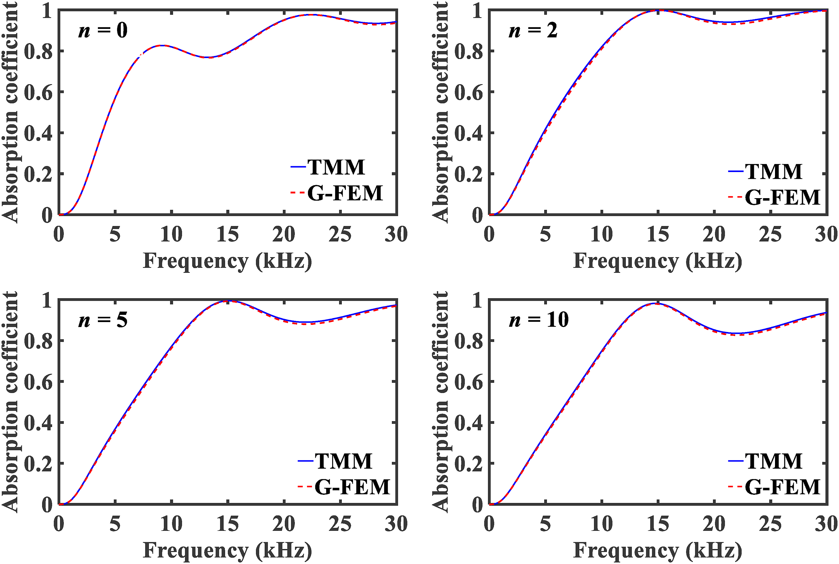
Results and discussions
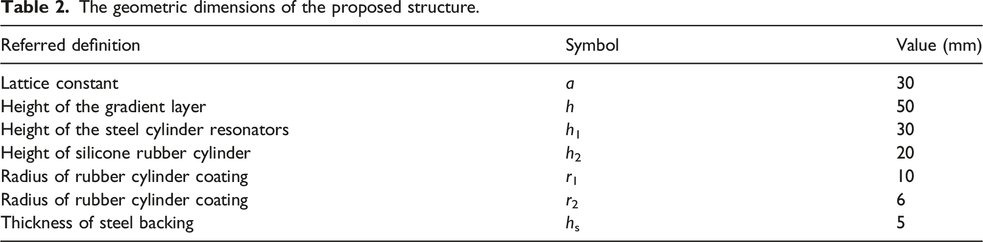
The geometric dimensions of the proposed structure.
To validate the acoustic characterizes of the designed absorber, the sound absorption coefficients of FGMs with LRs under different gradient indices are compared first, as shown in Figure 6. It is obvious that compared to homogeneous materials with LRs (that is, gradient index n = 0), the sound absorption performance of FGMs with LRs has improved in the mid-high frequency range. In addition, with the increase of the gradient index n, the second absorption peak shifts to the high frequency and the sound absorption coefficient of the structure in the mid-high frequency band is enhanced. It can be seen from equations (5)–(7) that with the increase of the gradient index n, the Young’s modulus of any thickness in the structure will increase, resulting in the increase of the resonance frequency of the acoustic structure, and the second absorption peak of the structure mainly hinges on the resonance characteristics of the structure; thus, the absorption peak of the structure moves to high frequency. On the other hand, the sound absorption effect of the structure at non-resonant peaks in the mid-high frequency range mainly depend on the energy dissipation mechanism of the material to the sound wave. With the increase of the gradient index, the loss factor of any thickness in the gradient layer of the structure will also increase, so the attenuation of the sound wave in the material is greater, which makes the sound absorption coefficient of the material increase in the mid-high frequency. Furthermore, the material properties of LRs determine the frequency position of the first sound absorption peak, so the increase of the gradient index will not affect the frequency range of the first absorption peak. Therefore, with the increase of the gradient index n, the sound absorption performance of the structure in the mid-high frequency range is effectively improved. The sound absorption performance of the functionally graded materials with local resonators under different gradient indices.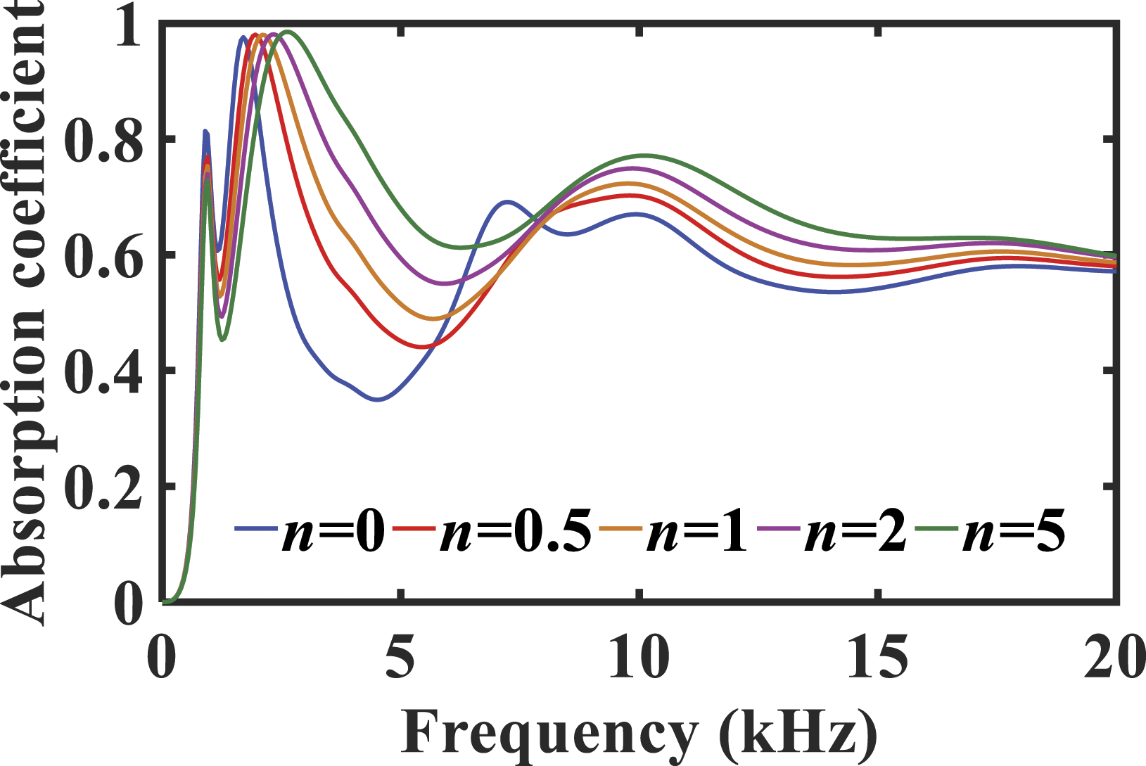
Figure 7 presents the acoustic characteristics of the FGMs with LRs and without LRs under different gradient indices. It can be found that compared with the FGMs without LRs, FGMs in which LRs are embedded can form a low-frequency absorption resonance peak according to local resonance mechanism, and expand the low-frequency absorption range. Another noteworthy aspect is that the sound absorption of the structure mainly relies on the dissipation mechanism of viscoelastic materials in high frequency band. When LRs are embedded, the viscoelastic materials of the acoustic structure are reduced, which reduces the sound absorption effect of the high frequency band. This is also a shortcoming of the sound absorption structure with the local resonance mechanism. A characteristic of FGMs is that the surface of the material in contact with the fluid matches the impedance of the fluid medium, which makes it easier for the sound wave to enter the structure. Simultaneously, the sound energy will be fully dissipated and attenuated as the loss factor in the propagation direction of the sound wave increases. Therefore, coupling application of FGMs with LRs can further enrich the sound absorption characteristics of materials and obtain better sound absorption effect of the underwater anechoic coating. The sound absorption performance of the functionally graded materials with LRs and without LRs under different gradient indices. LR: local resonators.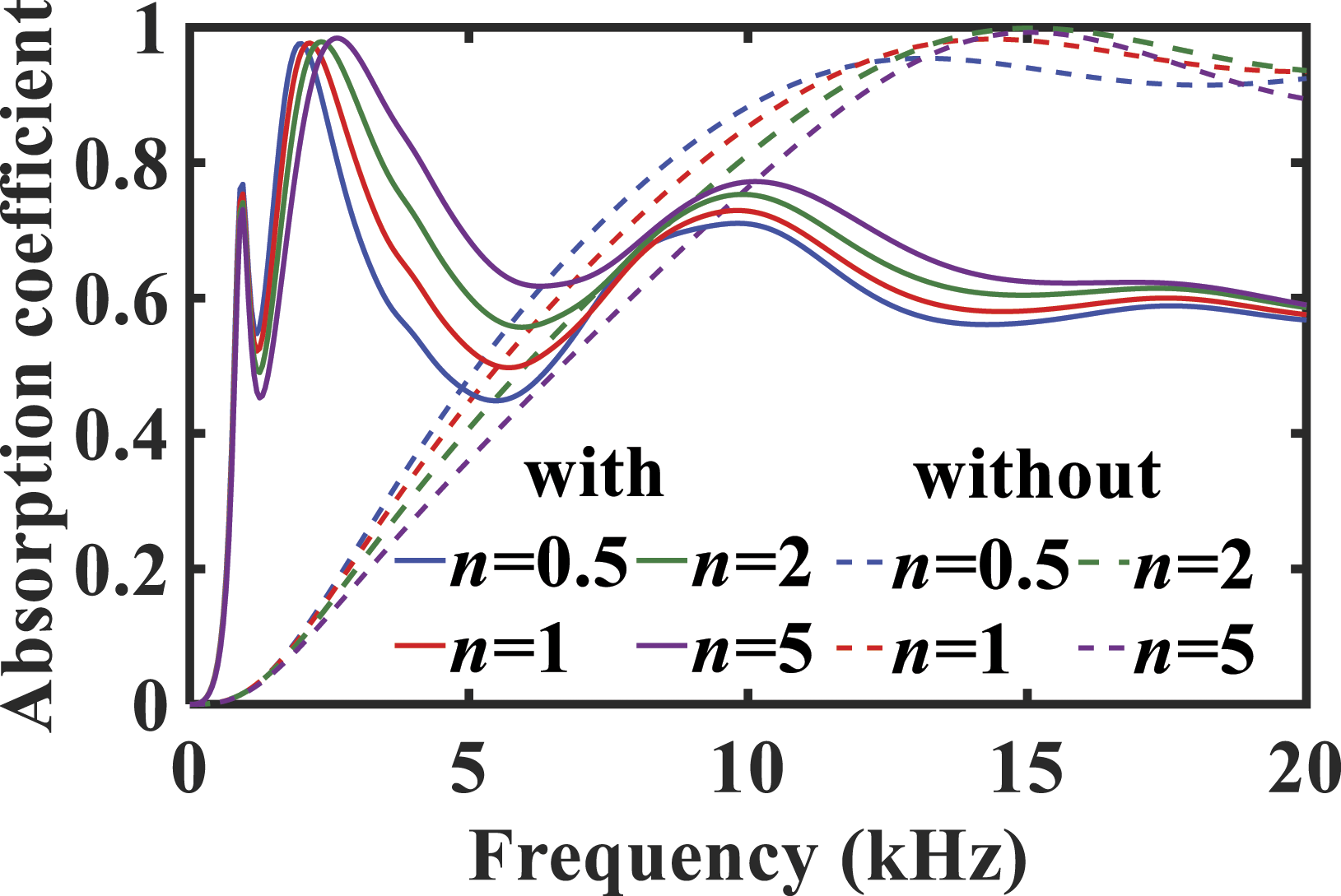
Figure 8 shows the total displacement vector field and its cross-sectional view of a periodic unit for the proposed structure at the special frequency, in which the deformation of the eigenmode shape is also shown. These modules are calculated under the condition of gradient index n = 5. It can be found that the first sound-absorbing peak is produced at 951 Hz, and the vibration displacement is mainly gathered on the local resonance unit, while the vibration displacement is mainly gathered on the plate backing and the gradient material layer at the second sound-absorbing peak (2601 Hz). Also, the dissipation of acoustic energy is mainly related to the dissipation characteristics of materials in the middle and high frequency bands. At the third sound absorption peak frequency (10,001 Hz), the longitudinal waves in FGMs scatter when they contact LRs. Scattering is accompanied by waveform conversion, which converts longitudinal waves into shear waves. It will change the propagation direction of sound waves, expand the propagation path of sound waves, and intensify the bending vibration of structures, leading to high deformation of the rubber coating covering the steel cylinder, thus increasing the energy loss of sound waves. Accordingly, the gradient matrix layer plays a major role in the mid-high frequency sound absorption, and local resonance unit has a great effect on improving low-frequency sound absorption. Therefore, through the above research on the sound absorption mechanism of this structure, a basis for analyzing the influence factors of sound absorption has been provided. The vibration displacement and eigenmode deformation of a periodic unit of the proposed structure, and its cross-sectional view of the displacement vector fields at the special frequency. (a) fre = 951 Hz. (b) fre = 2601 Hz. (c) fre = 10,001 Hz.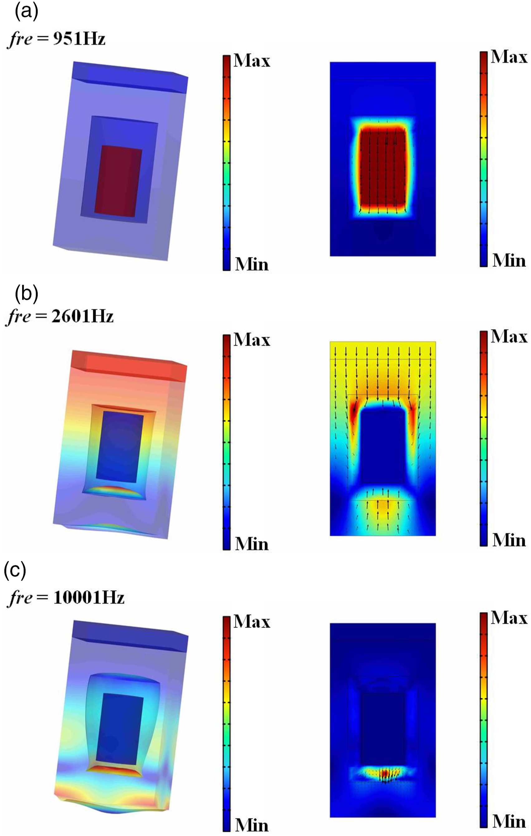
To investigate the influence of the material properties of the gradient layer on the designed acoustic structure, the influence of Young’s modulus, loss factors, and densities of the inorganic filler on the acoustic characteristics of the structure is studied under different gradient indices.
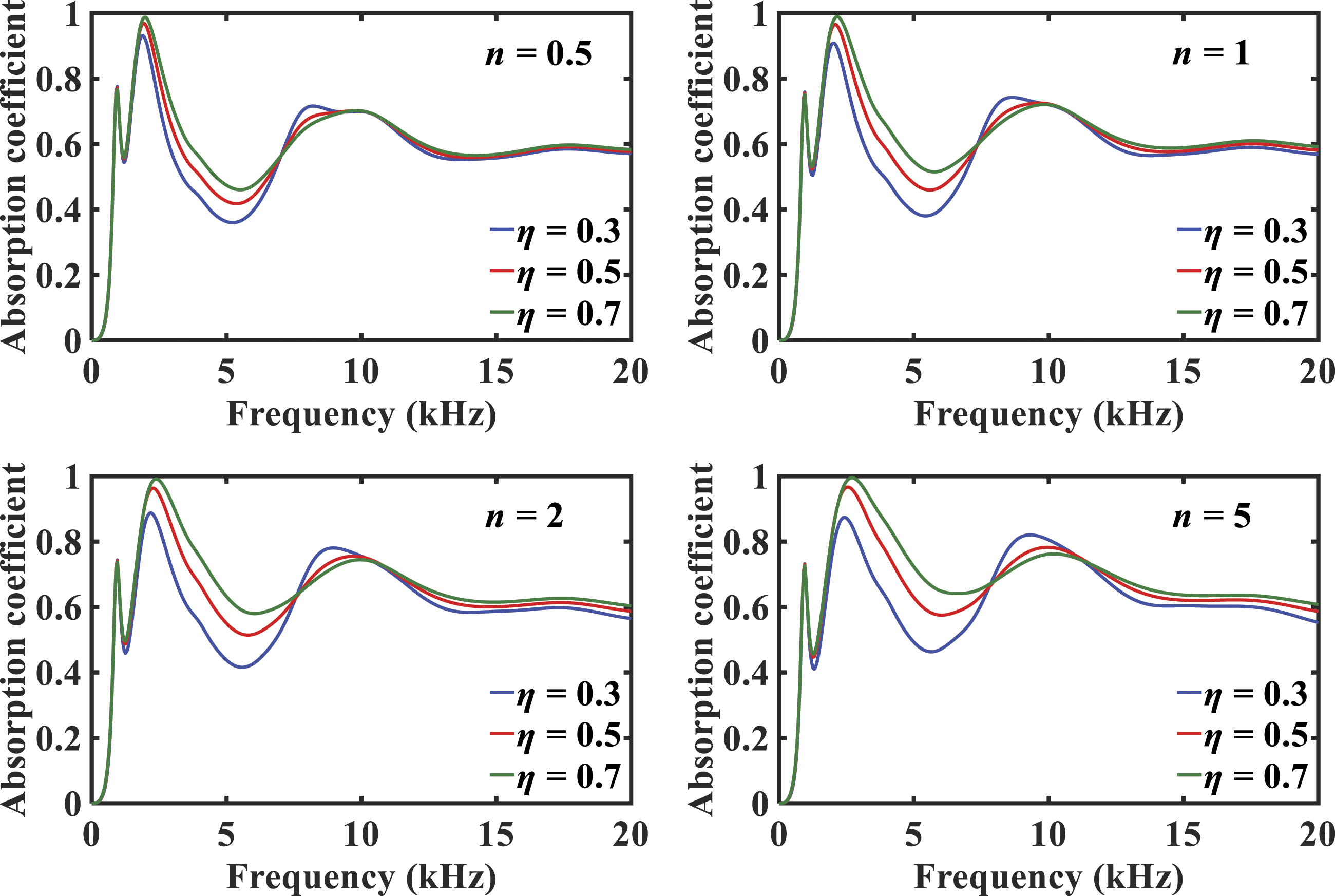
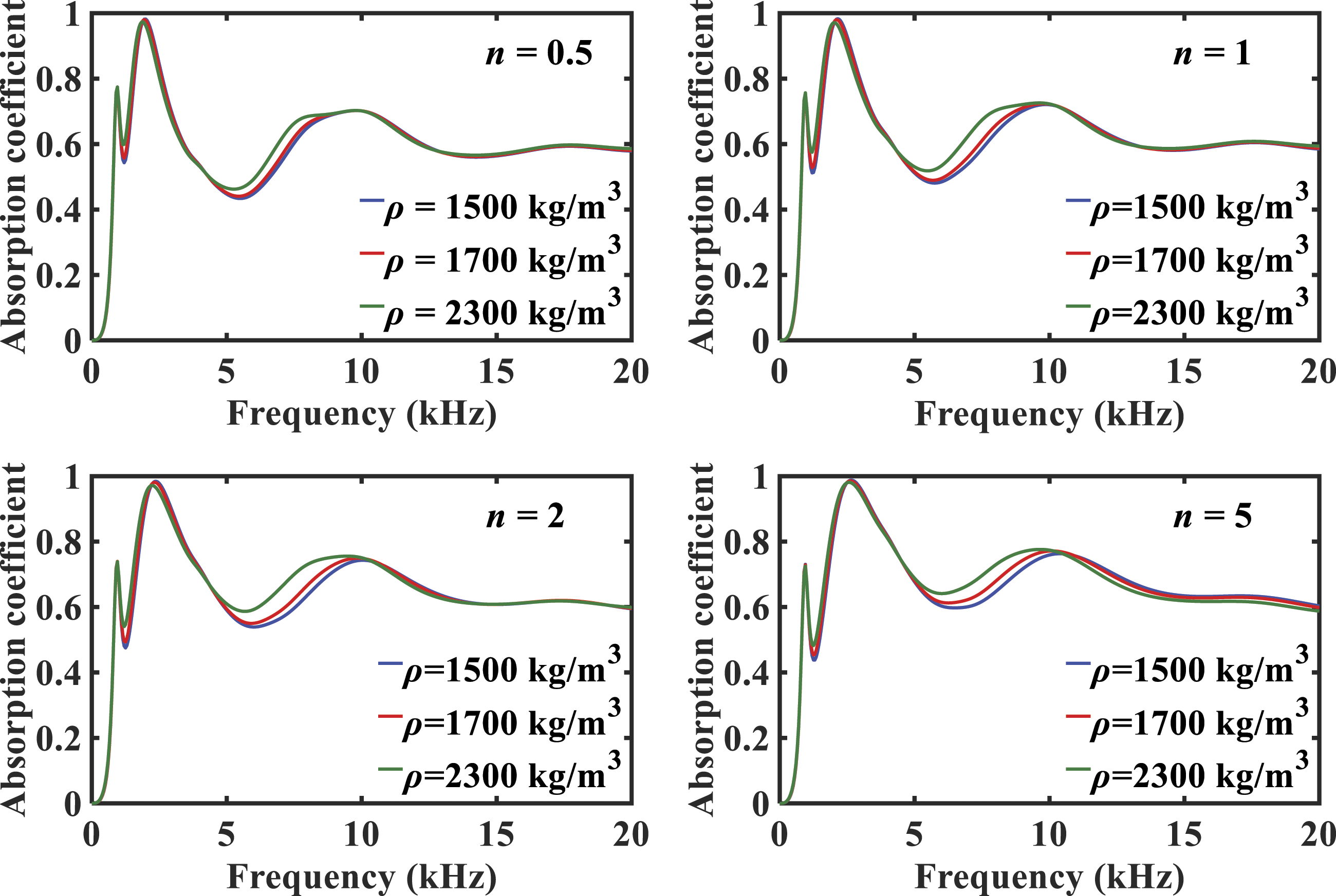
Figure 9 presents that as the Young’s modulus of the inorganic filler increase, the second absorption peak frequency increases, and sound absorption coefficients enhance in the mid-high frequency band. This is because the increase of the Young’s modulus of the inorganic filler increases the equivalent Young’s modulus of the gradient material layer along the thickness direction z. According to the previous analysis, the increase of the Young’s modulus of the gradient layer not only shifts the second sound-absorbing peak to high frequencies but also increases the acoustic impedance of the gradient material layer, thereby increasing the sound absorption coefficients in the non-resonant frequency range. Figure 10 presents that with the increase of loss factor of inorganic filler under different gradient indices, the acoustic absorption effect of the proposed structure increases in the range of mid-high frequency. Because in the mid-high frequency band, the absorption effect of the structure mainly hinges on the energy dissipation mechanism of the sound wave in the material. Hence, the equivalent loss factor of the gradient layer of the acoustic structure increases with the increase of the loss factor of the inorganic filler, which enhances the sound wave energy dissipation in the material, so the sound absorption coefficients increase. Figure 11 presents the influence of different inorganic filler densities on the sound absorption performance of the proposed structure under different gradient indices. It can be found that as the densities of inorganic filler increase, the sound absorption performance in the middle frequency band is improved. It is because as the density of inorganic filler increases, the equivalent density of the gradient layer of the acoustic structure increases. Thereby, the characteristic impedance of the acoustic structure becomes larger, which enhances the sound wave energy dissipation in the material; thus, the sound absorption coefficients increase. In addition, with the increase of the gradient index, the Young’s modulus, densities, and loss factors of the inorganic filler increase along the thickness of the gradient layer at a faster rate, which makes the effect of the Young’s modulus, densities, and loss factors of inorganic fillers on the sound absorption performance of the proposed acoustic structure more and more obvious. Moreover, the parameters of the inorganic filler are almost independent of the first sound-absorbing peak frequency. Another aspect, because the first sound-absorbing peak is primarily affected by the LRs, changing the material properties of inorganic filler has little effect on it. The sound absorption performance of the proposed underwater acoustic coating with different inorganic filler Young’ modules under different gradient indices. The sound absorption performance of the proposed underwater acoustic structure with different inorganic filler loss factors under different gradient indices. The sound absorption performance of the proposed underwater acoustic coating with different inorganic filler densities under different gradient indices.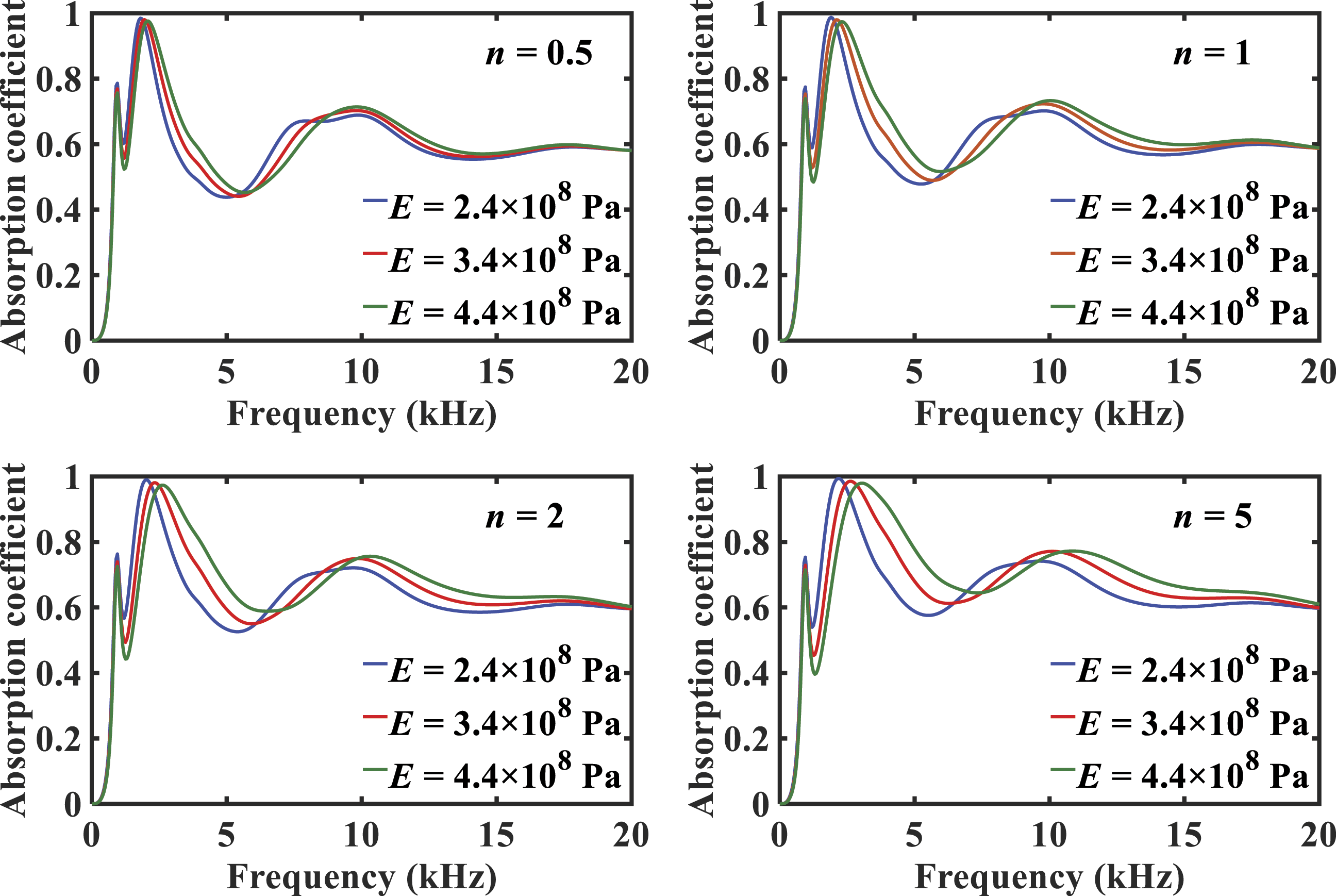
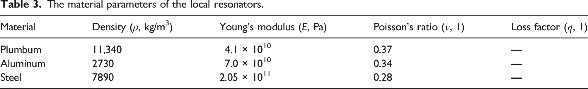
In this work, we study the influence of the materials of LRs on the acoustic performance of the structure under different gradient indices, as shown in Figure 12. The relevant material parameters are shown in Table 3. The results show that the sound-absorbing effect of the structure in the low-frequency range is better than the other two materials when the material of LRs is plumbum. According to the analysis above in Figure 8, the change of the resonator mass only affects the first sound-absorbing peak. When the filling rate of the local resonator remains unchanged and its mass decreases, the first sound-absorbing peak moves to high frequency and it couples with the second sound-absorbing peak, thereby improving the sound absorption effect at the wave valley between the two absorption peaks. As a result, when the material of the resonator is aluminum, the first sound-absorbing peak and the sound-absorbing absorption peak overlap together, so that the first sound-absorbing peak is not obvious. Correspondingly, increasing the gradient index of FGMs can significantly improve the mid-high frequency sound absorption effect of the structure. From these analyses, it can be concluded that by changing the material of LRs to adjust the position of the resonant absorption peak, the first and second sound-absorbing peaks are close to each other and coupled, so as to realize broadband sound absorption in a specific frequency range according to the practical needs. Comparison of sound absorption coefficients of functionally graded materials with different materials of local resonators under different gradient indices. The material parameters of the local resonators.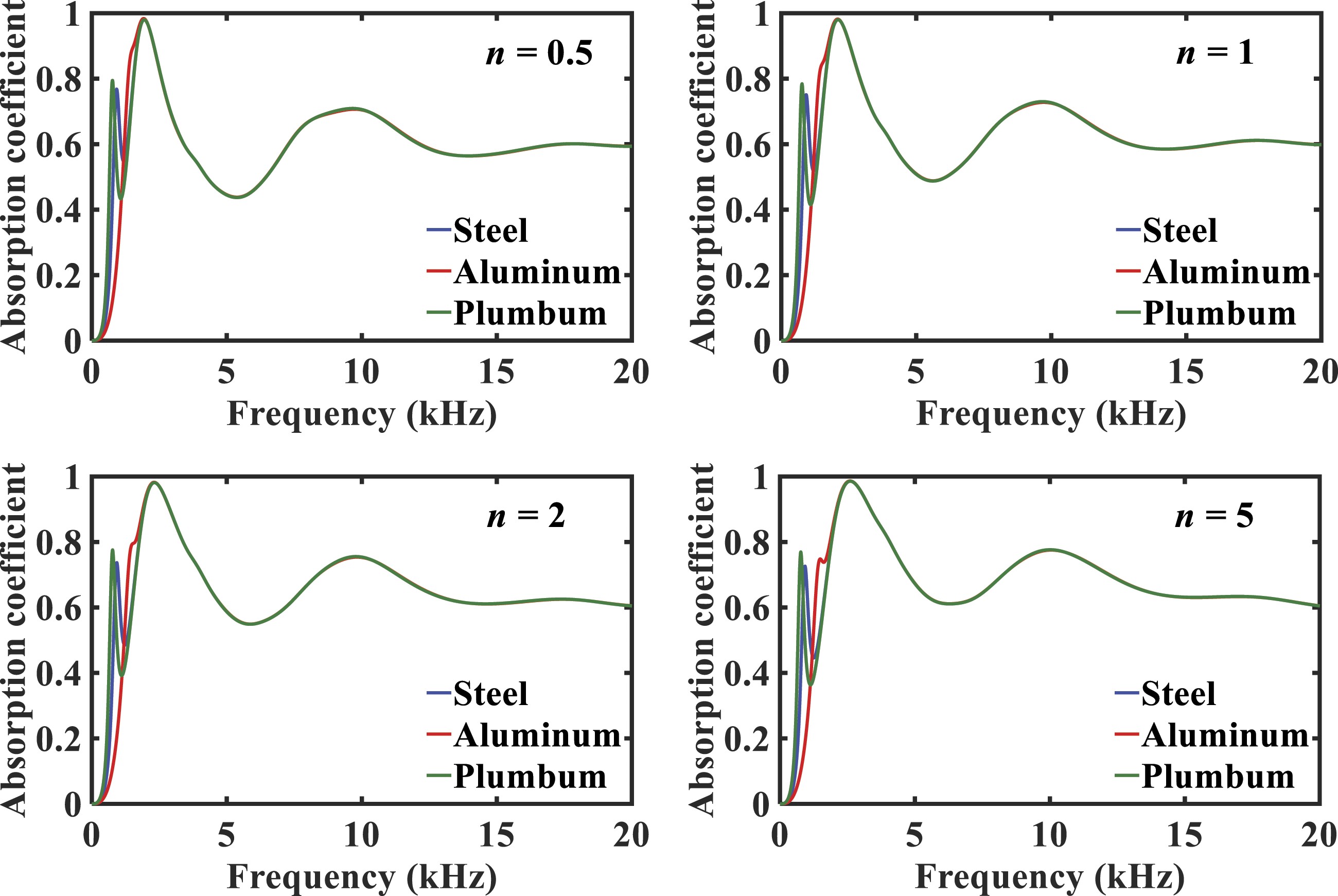
To further explore the sound absorption performance of the proposed structure, control the acoustic performance of the different resonator numbers combinations in the low-frequency range, and the acoustic structure models of double-resonator and multi-resonator are established, as shown in Figure 13. The radius and thickness of a single resonator in the double-resonator acoustic model are, respectively, r3 = 6 mm and h3 = 10 mm. The radius and height of a single resonator in the multi-resonator acoustic model are, respectively, r3 = 3 mm and h3=10 mm. It should be noted that other geometric dimensions are the same as above to ensure that the filling rate of the LRs is the same and evenly distributed in the rubber coating layer. Acoustic models of the functionally graded materials with different numbers of local resonators, front views, and top views. (a) The double-resonator. (b) The multi-resonator.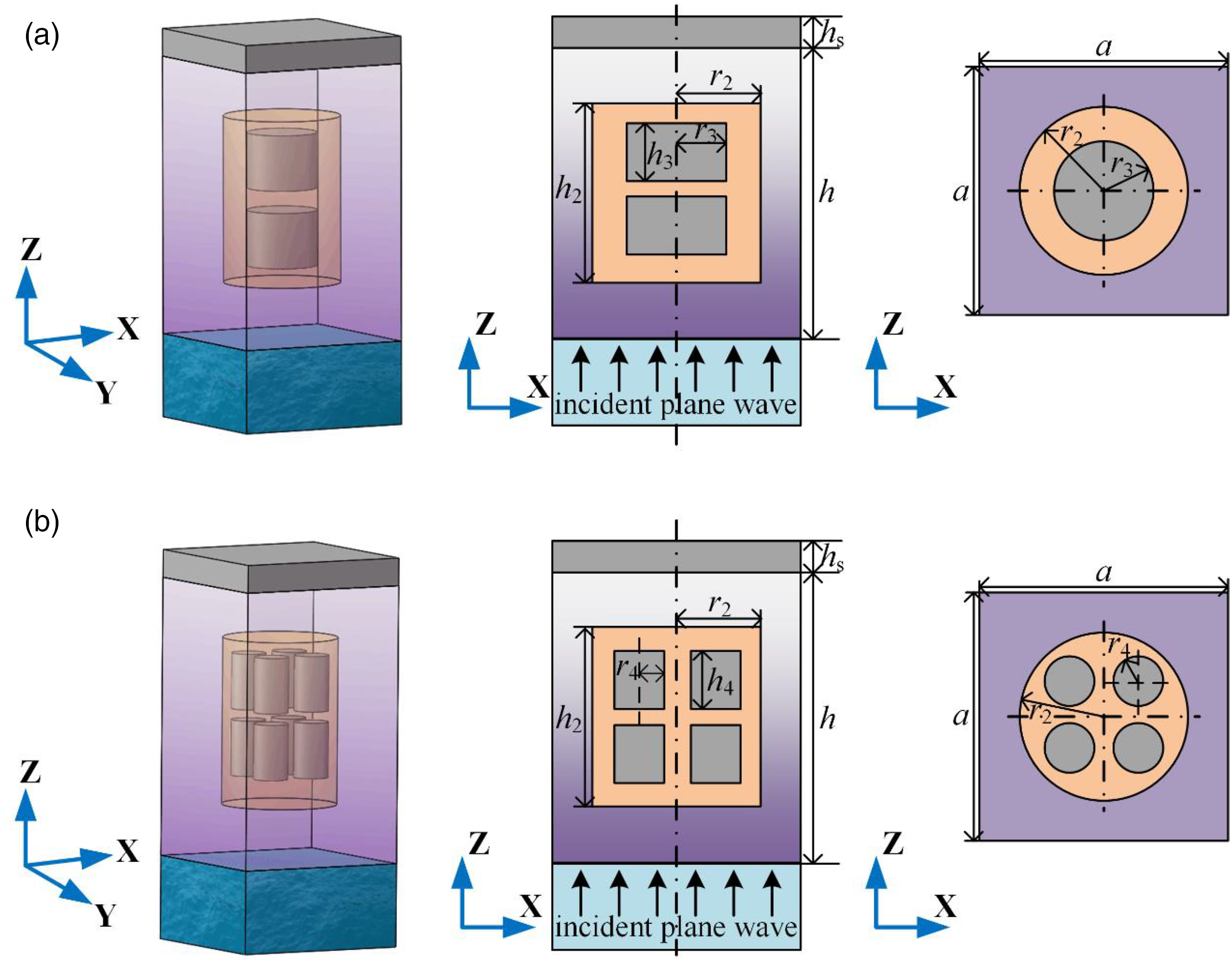
Figure 14 presents the sound absorption coefficients of the FGMs with different numbers of LRs under different gradient indices. It can be found that for the FGMs with multi-resonator, their sound absorption performance is superior to that of the FGMs with single-resonator. Moreover, with the increase of the number of the LRs, the improvement of low-frequency sound absorption effect is more obvious. Figure 15 shows the displacement vector fields of FGMs with different numbers of LRs at the first sound-absorbing peak (gradient index n = 5). It indicates that at the first sound-absorbing peak, the FGMs with multiple resonators not only has the vibration energy generated by the local resonance but also has the coupling vibration energy generated between different resonators. For another aspect, the mass of each single resonator is lower in the FGMs with multi-resonator than that of the FGMs with single-resonator. Accordingly, FGMs with multiple resonators have better sound absorption performance at the low frequency, and the coupling resonance frequency at the first absorption peak of the FGMs with multiple resonators is higher than that of the FGMs with single-resonator. The displacement vector fields of the FGMs with different numbers of LRs at the second sound-absorbing peak (gradient index n = 5) are shown in Figure 16. It can be seen that the vibration displacement energy caused by the acoustic pressure is concentrated on the gradient materials layer and steel backing. This is the reason why increasing the number of LRs hardly changes the position and intensity of the second sound-absorbing peak. In addition, with the increase of the gradient index n, the sound absorption performance of the structure is consistent with the above research. As the gradient index of the FGMs increases, the sound-absorbing effects of this acoustic structure in the middle-high frequency range can be enhanced. Comparison of sound absorption coefficients of functionally graded materials with different numbers of local resonators under different gradient indices. The displacement vector fields of a periodic unit of the functionally graded materials with different numbers of local resonators at the first sound absorption peak frequency. (a) The double-resonator. (b) The multi-resonator. The displacement vector fields of a periodic unit of the functionally graded materials with different numbers of local resonators at the second sound absorption peak frequency. (a) The double-resonator. (b) The multi-resonator.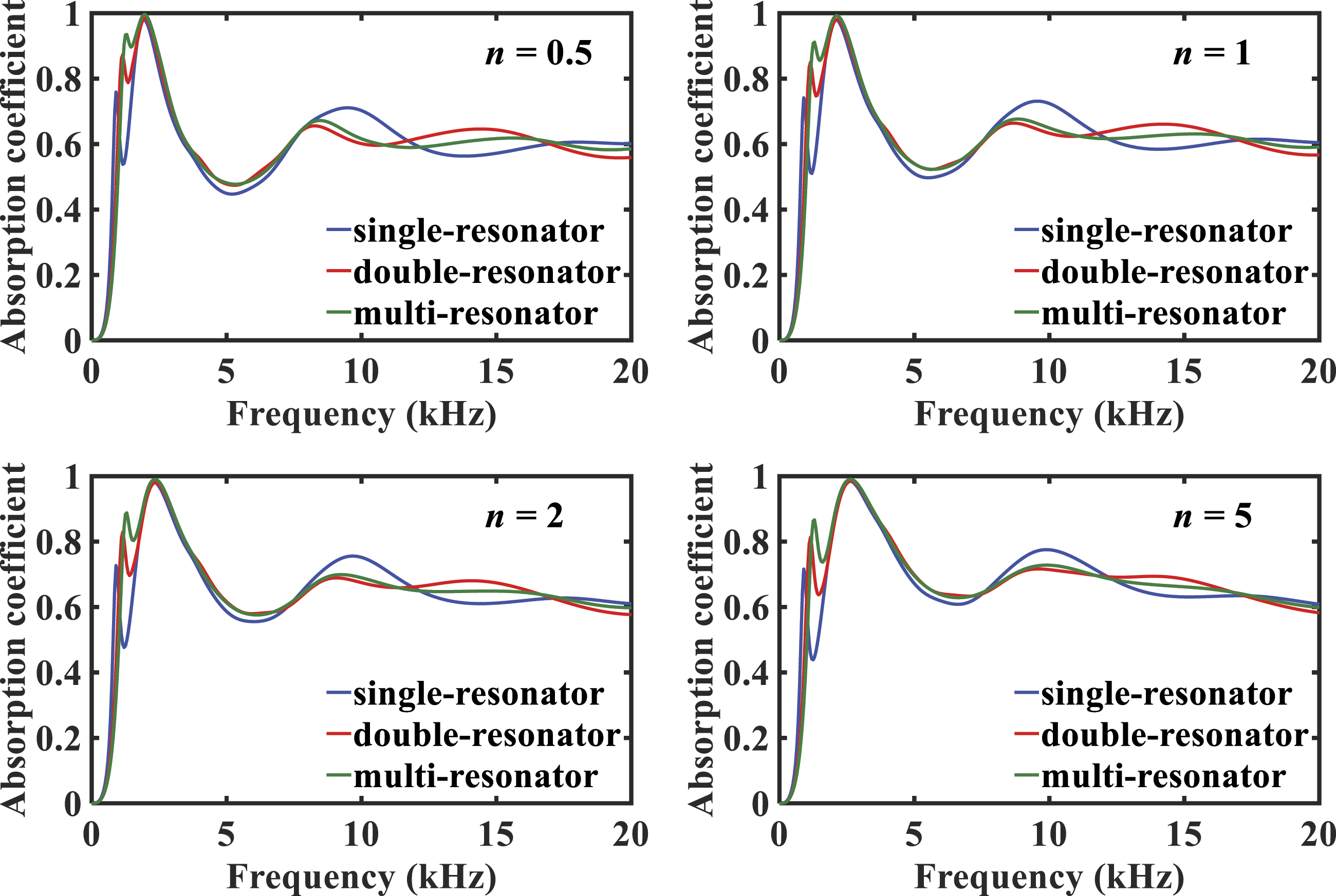
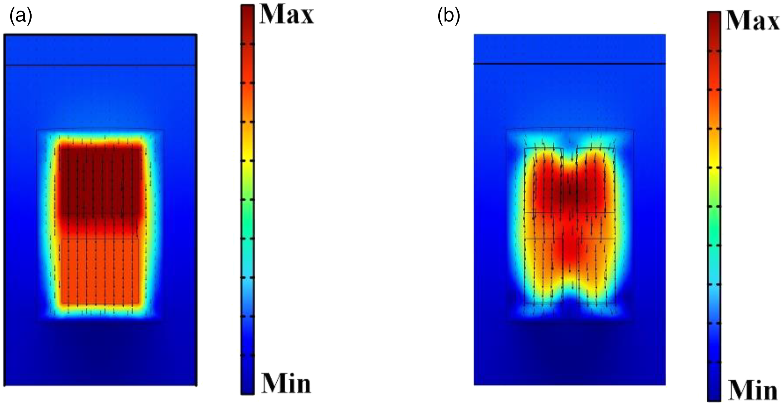
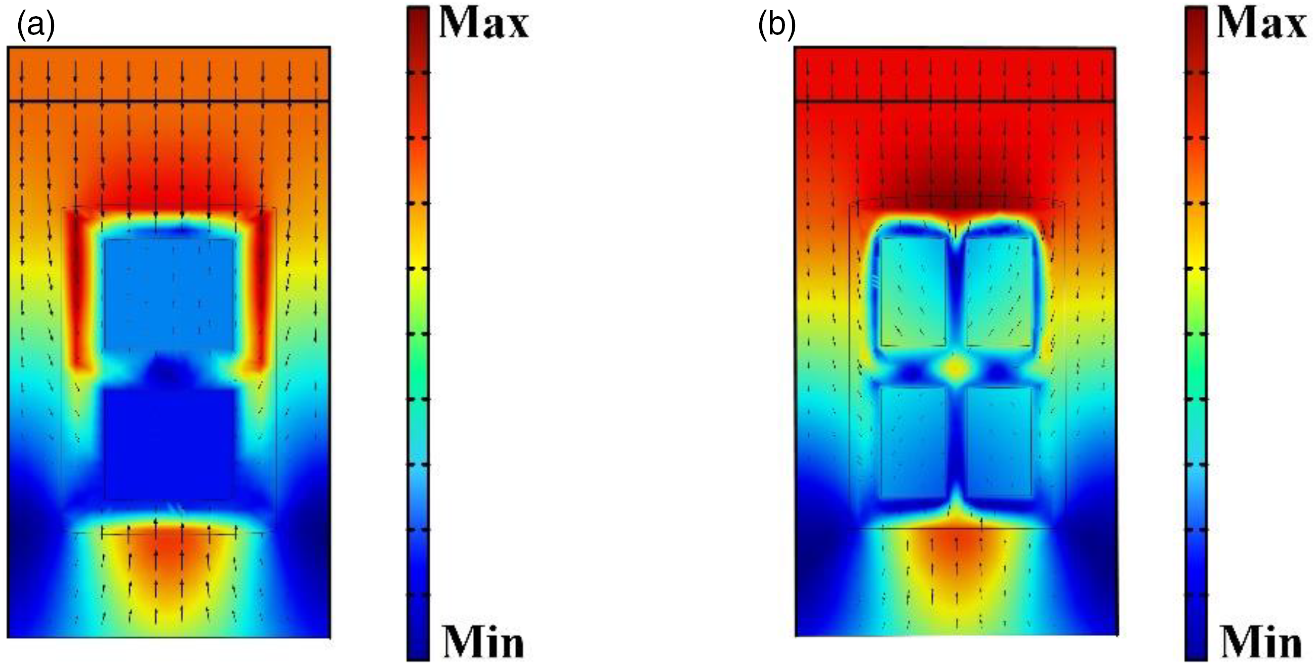
Figure 17 shows the influence of the radii of LRs on the sound absorption effect of the FGMs with LRs. In the same structure, the increase in the radius of the resonator means the increase in the filling rate of the resonator. As the filling rate of resonators increases, the first sound-absorbing peak at the low-frequency position is greatly enhanced. Also, the second absorption peak is hardly affected by the resonator filling rate because it is mainly caused by the resonance characteristics of the structure. Similarly, as the gradient index of the FGMs increases, the sound-absorbing effect of this acoustic structure in the mid-high frequency range can be enhanced. Comparison of sound absorption coefficients of functionally graded materials with different radii of local resonators under different gradient indices.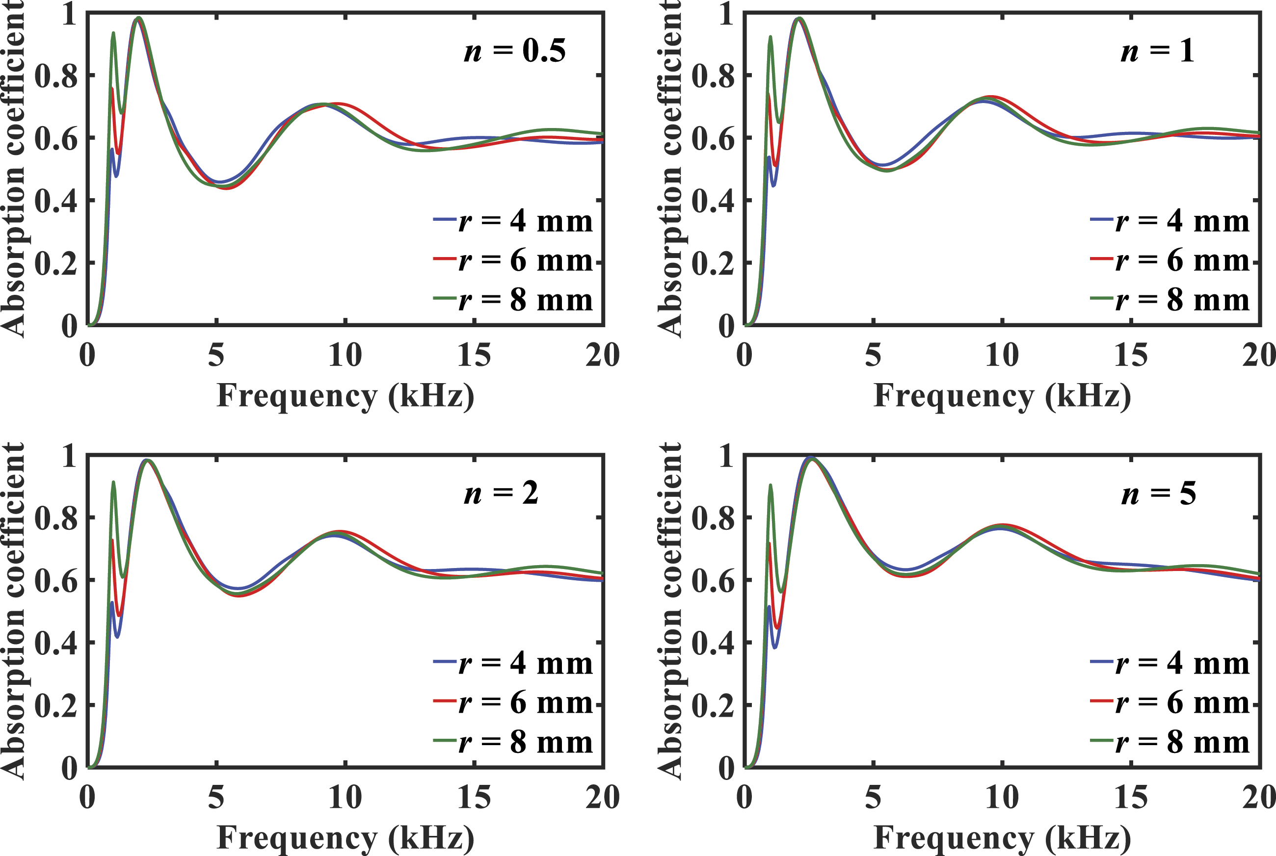
To investigate the effect of the structural forms of LRs on the acoustic performance of the anechoic coating, the conical and truncated conical LRs are selected as the research objects. Figure 18 shows their structures. Under the condition that the filling rate of LRs and other geometric dimensions remains unchanged, the dimensions of different structural forms of resonators are shown in Table 4. Acoustic models of the functionally graded materials with different structural forms of local resonators, front views, and top views. (a) The conical resonator. (b) The truncated conical resonator. The geometric dimensions of local resonators in different structural forms.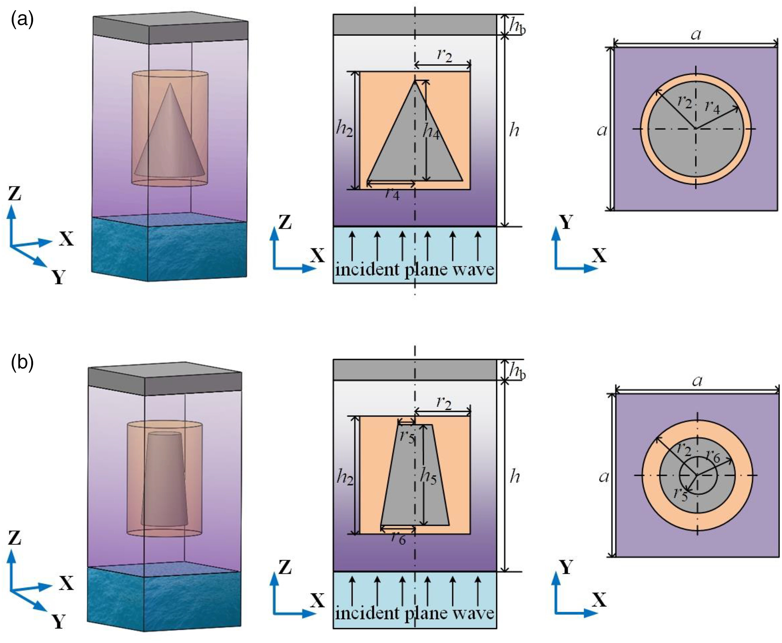
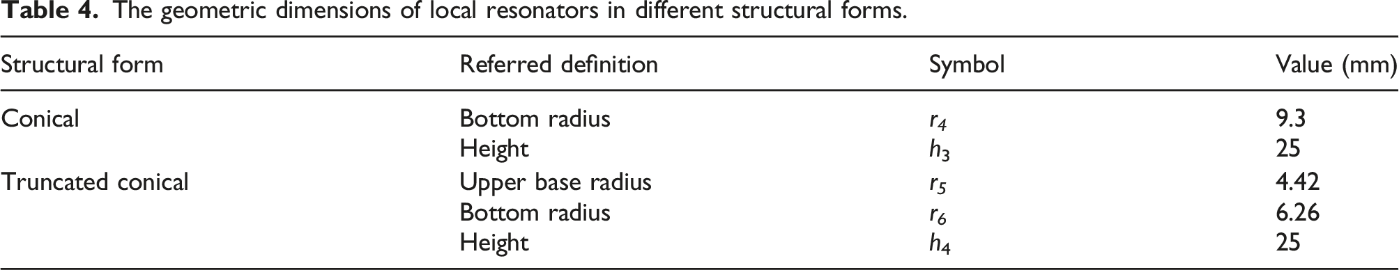
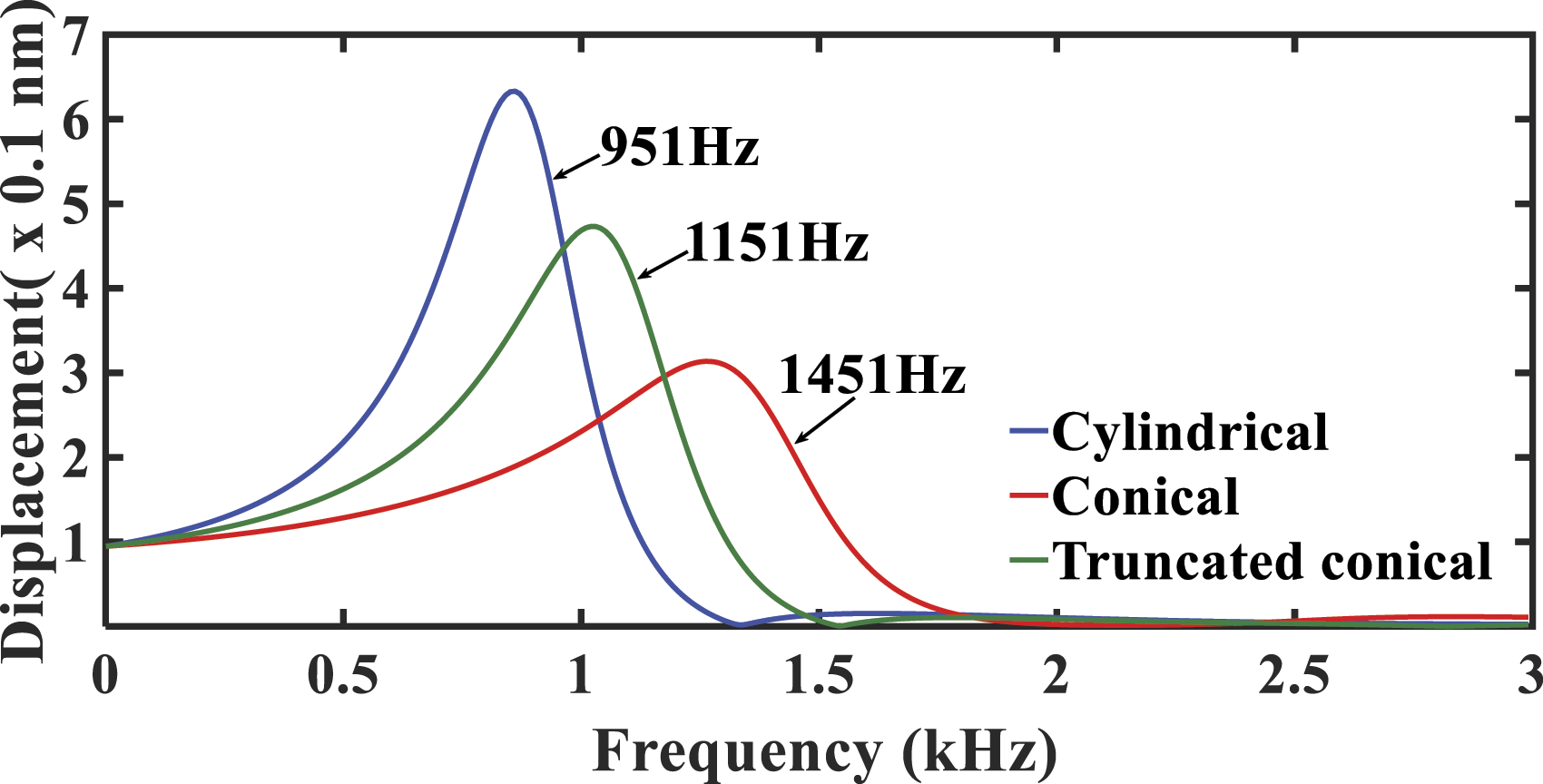
Figure 19 illustrates the impact of the three structural forms of LRs on the sound absorption performance of the designed structure under different gradient indices. It can be noticed that the acoustic characteristics of the structure change as the shape of the resonator changes. In order to reveal the mechanism of the change in the form of the resonator on the sound absorption performance of the structure, Figure 20 shows the change law of the average displacement of three forms of resonators in the frequency range of 0–3000 Hz (gradient index n = 5). Herein, the frequency points of the three structural forms at the first sound absorption peak are marked in Figure 20 (951 Hz, 1151 Hz, and 1451 Hz). It can be noted that the displacement of the conical resonator is smaller than the other two at the first resonance peak. That is, in the spring-mass system composed of rubber coating and LRs, the equivalent stiffness of the conical resonator is greater. Because the masses of the three structural forms of resonators remain the same, the frequency of the first sound-absorbing peak of the conical resonator is higher and the peak value is larger than the other two forms. Additionally, the sound absorption valley of the first and second formants is improved due to the coupling between the first and second formants. The second absorption peak is caused by the structural resonance of the steel backing and gradient matrix, so changing the form of the resonator has little effect on the second absorption peak. Comparison of sound absorption coefficients of functionally graded materials with different structural forms of local resonators under different gradient indices. The resonator displacement of functionally graded materials with three structural forms at a frequency of 0–3000 Hz.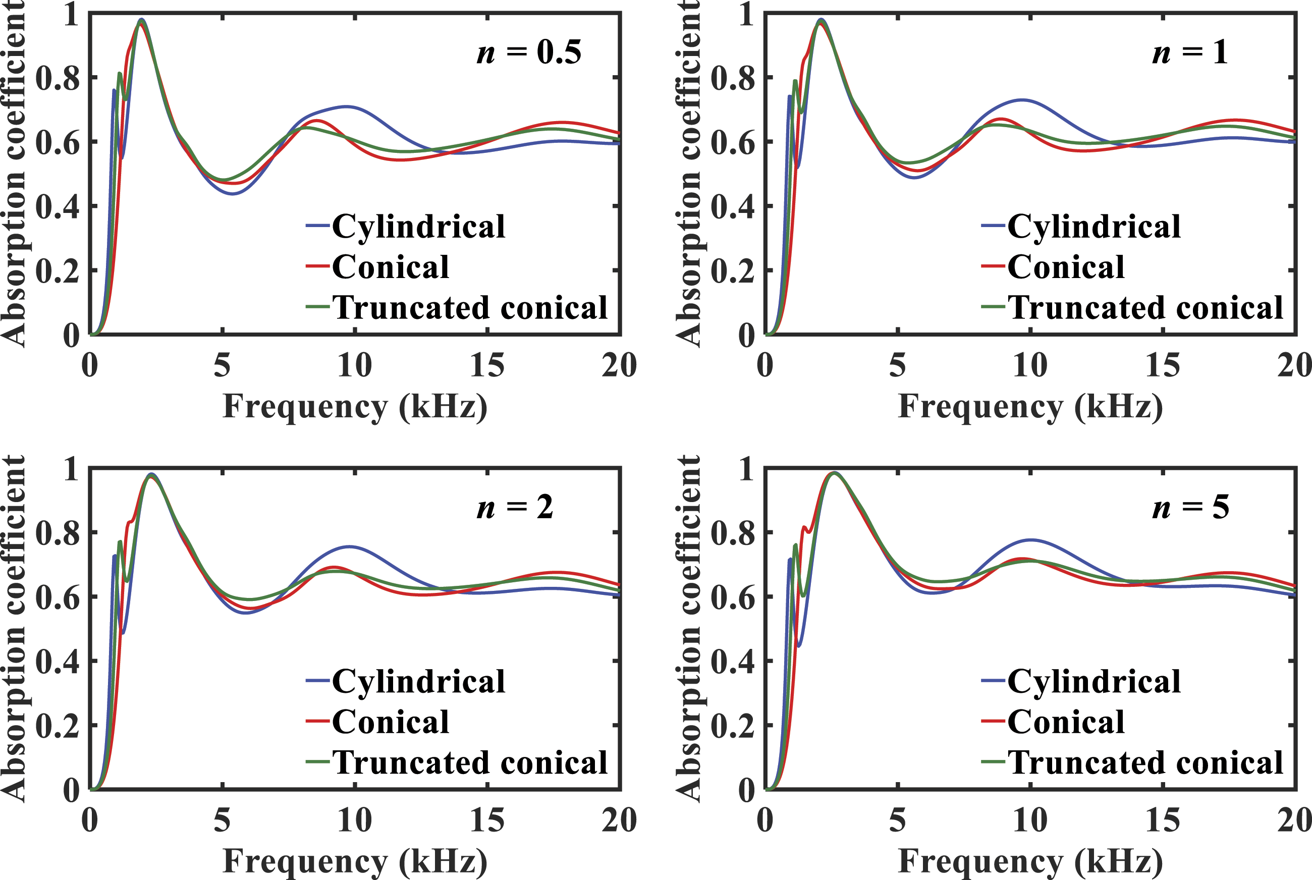
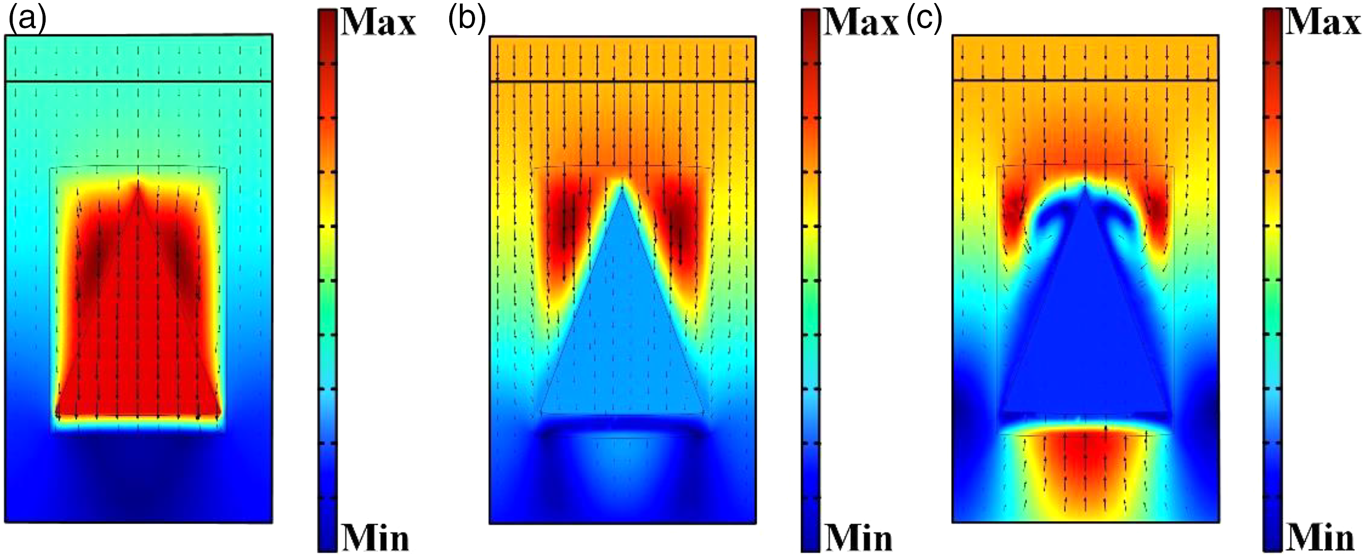
Figures 21 and 22, respectively, show the vibration displacement modal diagrams of the truncated conical and conical resonator at the first and second absorption peak frequencies and the valley frequencies between the two (gradient index n = 5). It can be noticed that the vibration energy is mainly gathered on the local resonance unit at the first absorption peak (1151 Hz, 1451 Hz). The vibration energy is mainly gathered on the plate backing and the gradient layer at the second absorption peak (2601 Hz, 2551 Hz). These are independent of the structural form of the resonators. It can be seen from the modal diagram that the vibration energy of the conical resonator structure at the first absorption peak is not only concentrated at the local resonance unit but also distributed in the plate backing and gradient matrix. Therefore, the sound absorption effect of the first absorption peak is enhanced. This is explained by the fact that the first and second sound absorption peaks are very close, resulting in a coupling effect. At the sound-absorbing valley frequency (1401 Hz, 1651 Hz), the energy accumulation mode of the vibration displacement presents a transitional state. The main energy gathering mode of the vibration displacement transitions from the first sound-absorbing peak to the second sound-absorbing peak. As a result, the first absorption peak moves to the high frequency, accelerating this conversion of this energy accumulation mode, and there is a coupling effect of the two sound absorption mechanisms, so that the sound absorption effect of the sound-absorbing valley significantly improved. Similarly, with the increase of the gradient index, the law of influence on the sound absorption performance of the structure is consistent with the previous analysis. By increasing the material gradient index, the sound absorption performance in the mid-high frequency range of the acoustic structure can be well improved. According to the above analysis, the position of the sound absorption peak in the low-frequency band can be tailored by changing the structural form of resonator to further optimize the sound absorption performance to meet practical needs. The displacement vector fields of a periodic unit of the functionally graded materials with truncated conical resonator at the sound absorption peak and valley frequency. (a) first peak frequency 1151 Hz. (b) valley frequency 1401 Hz. (c) second peak frequency 2601 Hz. The displacement vector fields of a periodic unit of the functionally graded materials with conical resonator at the sound absorption peak and valley frequency. (a) first peak frequency 1451 Hz. (b) valley frequency 1651 Hz. (c) second peak frequency 2551 Hz.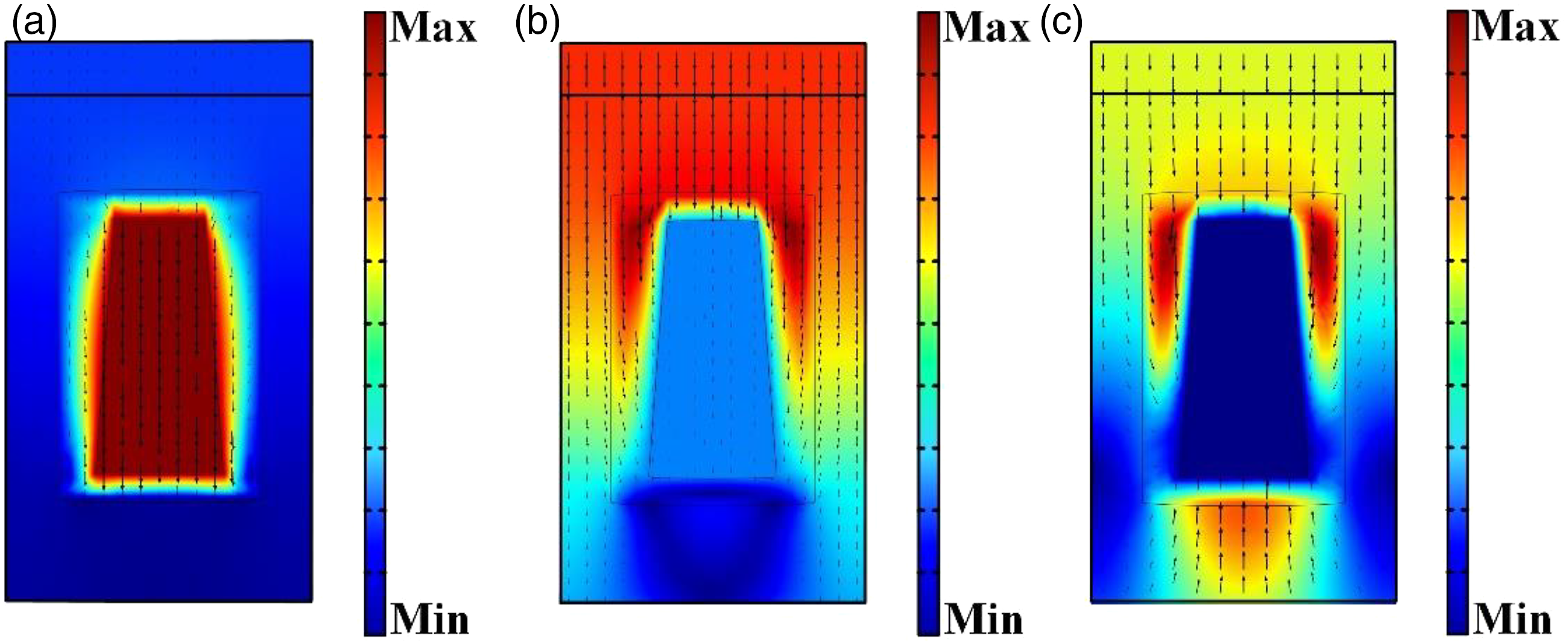
Conclusions
In this paper, an underwater anechoic coating made up of the FGMs embedded with LRs is developed to achieve effective low-frequency and broadband underwater sound absorption. The acoustic calculation model of the structure is established by the G-FEM, and the validity and correctness of the constructed model are verified by the TMM of the equivalent layered medium. Results demonstrate that the FGMs embedded with LRs can obtain a certain low-frequency sound absorption effect of the underwater acoustic structures compared to the FGMs without LRs. Compared with the traditional local resonance acoustic structure, when FGMs are used as the gradient matrix layer of the underwater anechoic coating. The FGMs not only have better matching characteristics from the impedance of the fluid medium to the impedance of the acoustic absorption structure but also increase the material impedance along the z direction of the gradient layer. The numerical simulation analyses of geometric and material parameters’ effects on acoustic absorption further enrich the optimization design scheme for the sound absorption performance of the structure. To obtain the optimal range of the parameters used, we refer to essential properties range of the structural materials and obtain the variation law of the sound absorption performance with the parameters through numerical simulation. According to this variation law and characteristics of the material itself, the optimal parameter range is determined, so as to provide references for practical engineering applications. Furthermore, the influence of the structural form and number of the LRs on the sound absorption performance is studied in this paper. Under the condition that the filling rate of resonators remains unchanged, the multi-resonator structure and the conical resonator structure can achieve better low-frequency sound absorption effect. Additionally, the article analyzes the sound absorption mechanism of the presented structure to understand the cause of sound absorption peaks. In summary, the novel underwater acoustic structure proposed in this paper provides ideas for improving the acoustic performance of underwater anechoic coatings.
Footnotes
Declaration of conflicting interests
The author(s) declared no potential conflicts of interest with respect to the research, authorship, and/or publication of this article.
Funding
The author(s) disclosed receipt of the following financial support for the research, authorship, and/or publication of this article: The National Natural Science Foundation of China (grant number 51822902) provided partial support for this work.