In present work, the double and triple-frequency synchronization behaviors of a vibrating mechanical system with two different driving frequencies, driven by three reversed rotating exciters, are investigated by theory, numeric, and experiment. Based on Lagrange’s equations, the dynamic model corresponding to vibrating machine is proposed and motion differential equations are constructed. The Bogoliubov standard formal equations for three exciters are established, by introducing the asymptotic method, in which the synchronization problem is converted into that of the existence and stability of zero-valued solution of the average differential equations. The synchronization criterion of satisfying the synchronous operation is deduced. According to the Routh–Hurwitz criterion, the stability criterion of the synchronous states is achieved analytically. Based on the obtained theory results, the stability characteristics of the system, are numerically discussed in detail, including the stability ability coefficients and stable phase differences. Finally, simulations and experiments under the condition of two different driving frequencies, are performed to further examine the validity of the theoretical and numerical qualitative results. The present work can provide a theoretical reference for designing some new types of the vibrating machines with adjustable frequencies and motion trajectories.
Vibrations have both harmful and beneficial aspects. For the former, some vibration isolation methods have to be proposed to minimize their harmful aspects as possible;1-3 while in light of the latter, the energy of vibration can also be accumulated and utilized, which leads to the inventions of many vibrating machines.4-20
In civil, mineral, and industrial engineering, especially in vibration utilization engineering, utilizing vibration effects and synchronization theory of exciters (generally unbalanced rotors driven by induction motors), many vibrating machines can be designed, manufactured, and used in industry production process, based on which the crushing, screening, conveying, ball grinding, dewatering, drying, cooling and so on, of all kinds of raw materials, are realized. It is, therefore, very necessary to deeply study the corresponding vibrating machines designed by synchronization, in order to meet the more and more high technology requirements of industries.
In light of the theory problems referred to vibration utilization engineering, most of them are characterized by nonlinear, and many nonlinear dynamic analytical methods, including the equivalent linearization method, the harmonic balance method, the multiple scales method, the averaging method of modified small parameters, and the asymptotic method, have to be used to derive the approximate solutions of nonlinear vibrating systems. Especially in vibration utilization engineering, the synchronization issue of exciters, being as one particular type of nonlinear phenomenon of vibrating system, is also an interesting research topic and has been discussed extensively.
As early as 1960s, Blekhman4-7 firstly proposed the theoretical explanation for the synchronization of two identical exciters, which attracted a great deal of attentions from scholars due to its potential practical application value. Subsequently, Inoue and Araki8 investigated the multiple cycle synchronization of exciters. Wen et al.9,10 further studied the synchronization of high order harmonic and sub harmonic frequencies in a nonlinear system and concluded that times-frequency synchronization of various harmonics can be achieved. Later, Balthazar et al.11,12 presented some numerical simulation results of the synchronization of two (or four) non-ideal exciters on a flexible portal frame structure. Considering the effects of key parameters on the synchronization of the system, including structural parameters, friction coefficients, and motor characteristic coefficients, Zhang et al.,13-15 investigated synchronization and stability of the vibrating system driven by two exciters, in which the Sommerfeld effect of the system is revealed in detail, as well as the synchronization of three rollers. Fang et al.16,17 revealed the intrinsic mechanisms of the synchronous phenomenon in a dual-pendulum-rotor system by employing the Poincare method, also the controlled synchronization of eccentric rotors with double-frequency excitation was given by considering sliding mode control. By associating the ASMC algorithm with master-slave control structure and constructing the adaptive sliding mode controllers, the composite synchronization of three and four exciters driven by induction motors in a vibrating system was addressed by Kong et al.18,19 Chen et al.20 researched the synchronization of two eccentric rotors with the common rotational axis in a far-resonant spatial motion vibrating system.
In the abovementioned literatures,9,10,13-20 the key of solving the synchronization of exciters in the vibrating system, is to find and study the existence and stability problem of the periodic solutions of system. In other words, the problem of synchronization of exciters is simplified to that of the existence and stability of the zero solutions for their phase differences by using the average method. And there are also other methods to investigate the solution and stability of the system, such as the direct motion separation method,4-7 and the perturbation method,21-23 and variational iteration method.24
Although the synchronization theories of exciters in vibrating systems have been investigated and developed intensively both numerically and experimentally for years, it is observed that the abovementioned references mainly are focused on the synchronization issue under the precondition that the vibrating system is powered by the same frequency supply, and few investigations about the double and triple-frequency synchronization are considered. However, with the development of science and technology, many vibrating machines, especially for vibrating separation machines used in engineering, are needed to achieve more complex motion trajectories and different driving frequencies to improve their functions and efficiencies. Therefore, the double and triple-frequency synchronization principles of exciters and their stability characteristics, should be given sufficient attentions and exploration in detail.
In this paper, taking a dynamical model with three exciters and driven by two different frequencies, for example, we restrict our attentions to a far super-resonant vibrating system (i.e., the operating frequency of the system is about 3–10 times of its natural frequency) with small damping, and the theoretical, numerical, and experimental studies on double and triple-frequency synchronization of three exciters will be given. In the Differential Equations of Motion of a Vibrating System section, the dynamic model of the system is constructed and motion differential equations are deduced. Based on the asymptotic method, the theoretical conditions for implementing double and triple-frequency synchronization of the system are presented in the Times-frequency Synchronization of the Three Exciters section. Some numerical qualitative analyses are conducted in the Numerical Qualitative Analyses on Stability Characteristics section. Simulation and experiments are provided to validate the feasibility of theoretical results in the Simulations and Experimental Verifications section, respectively. Finally, the conclusions are summarized.
Differential equations of motion of a vibrating system
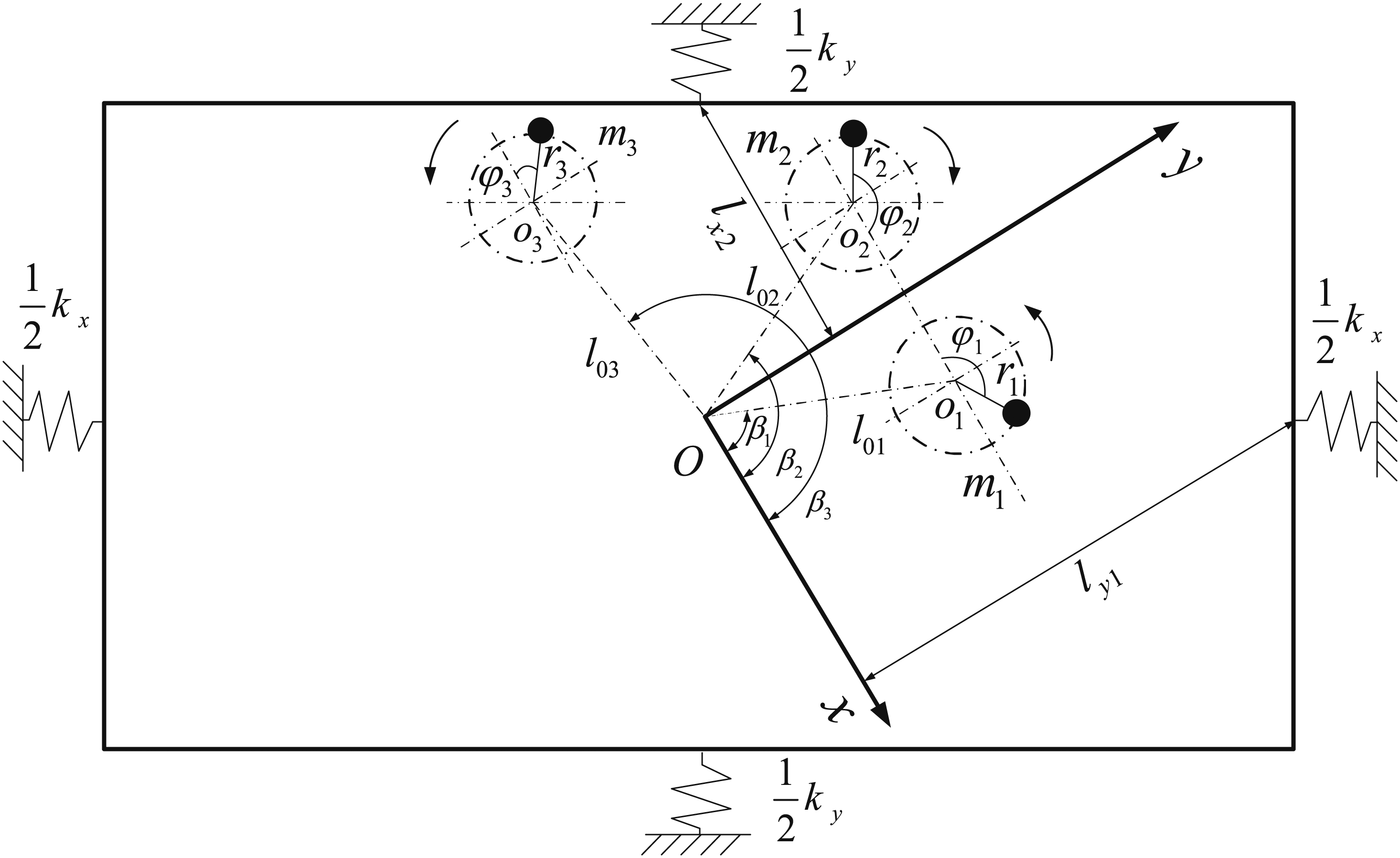
As shown in Figure 1, a dynamic model of considered vibrating system, which includes a rigid frame and three exciters (i.e., unbalance rotors driven by induction motors separately), and the rigid frame is connected to the foundation by springs installed symmetrically. The exciters one and three rotate in anticlockwise directions, and the exciter two rotates in clockwise direction. When the exciters one and two with uniform frequency supply are powered on and the exciter three is powered off, the motion trajectory of the rigid frame is a reciprocating linear motion along the y-axis direction, since the two counter-rotating exciters are mounted symmetrically on both sides of the y-axis. The synchronization of vibrating system driven by the two exciters has been well studied and not repeating it here. But in this paper, the specific vibration characteristics and motion trajectories of the system should be discussed when the three exciters implement double/triple-frequency synchronization, which is just the main focus of present work.
Dynamical model of the considered vibrating system.
In Figure 1, the point is the mass center of the system, the points , , and are the rotational axes of three exciters, respectively, and their rotational phases are denoted by , , and , respectively. The exciters one and two are powered with the same supply frequency, while the power supply frequency of exciter three is two or three times that of exciter one (or two). The vibrating system exhibits three degrees of freedom in plane motion: x, y, and . The displacement responses of the rigid frame in x- and y-directions are represented by x and y, and the swinging motion about its centroid is expressed as .
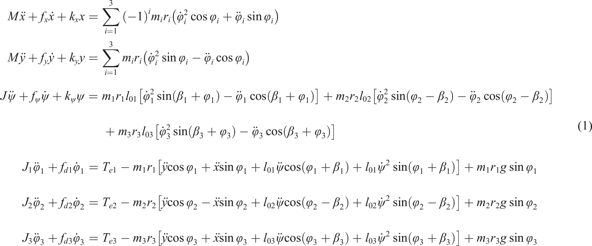
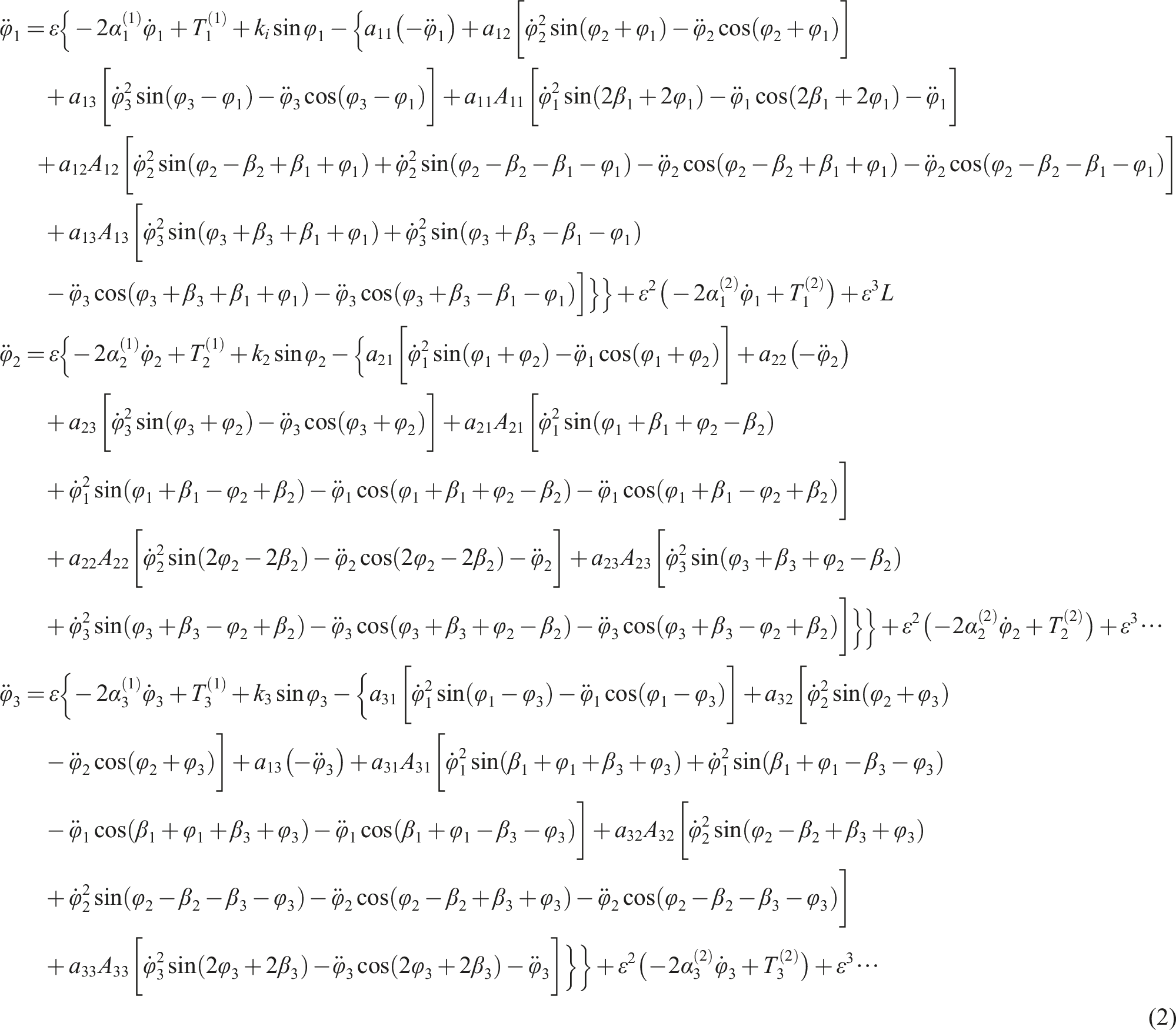
Choosing the , , , , , and as the generalized coordinates, and using Lagrange’s equations, the motion differential equations of the system can be directly derived in form
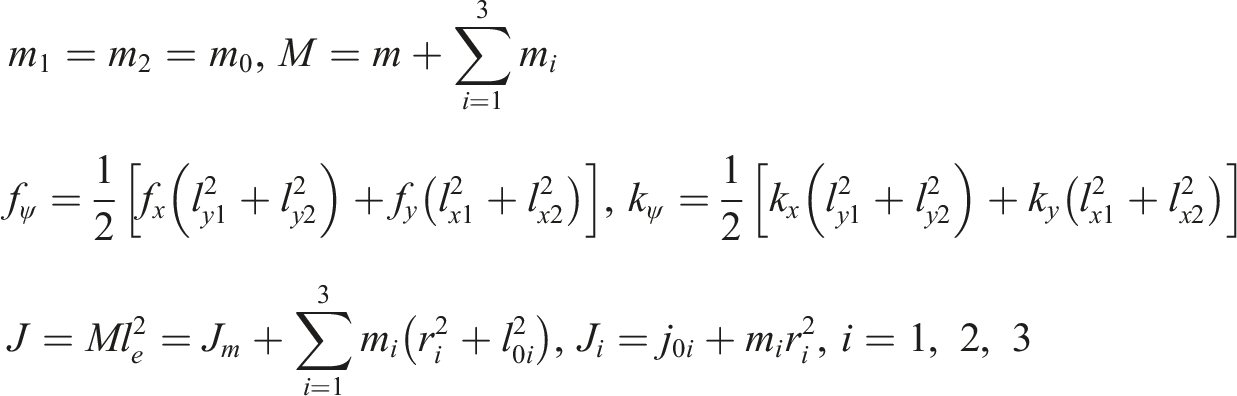
with
Times-frequency synchronization of the three exciters
Under the condition that the vibrating system operates in a far super-resonant state, the exciting frequency is far greater than the natural frequencies of the system, and the damping constants of springs are quite small. Hence, the second and third terms on the left-hand sides of equal signs in the first three formulas of equation (1), can be neglected, and the expressions of , , and are obtained. Inserting these results into the last three formulae of equation (1), then the approximate expressions concerning the angular accelerations of three exciters, can be expressed as
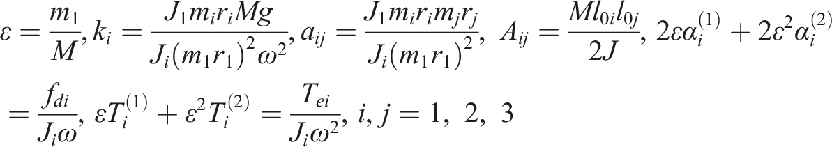
where
Here, the introduced small parameter , is dimensionless, and indicates the ratio of the mass of the exciter one to the total mass of the system. Moreover, considering that exciters one and two in Figure 1 are symmetrically distributed about the y-axis, there are
In order to establish the times-frequency synchronization relationship, the rotational phases of three exciters are set as
here, , denotes the fundamental angular velocity of the system, it is considered constant when studying the synchronous motion. Also, it is evident that is an independent variable changing from t to , and () is defined as the relative phase. During the steady operation process of the system, compared with the change of the rotational phase , that of is very small relatively, that is, can be considered as a slow-changing parameter.
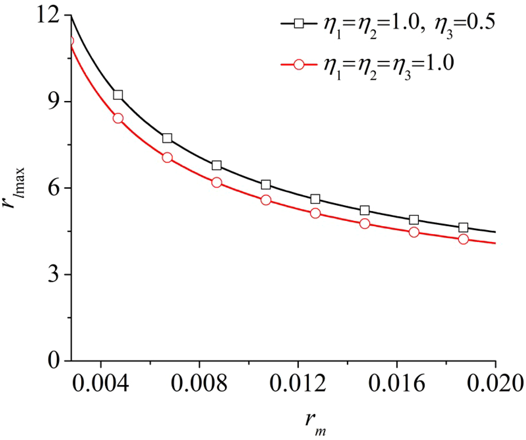
Values of versus for different .
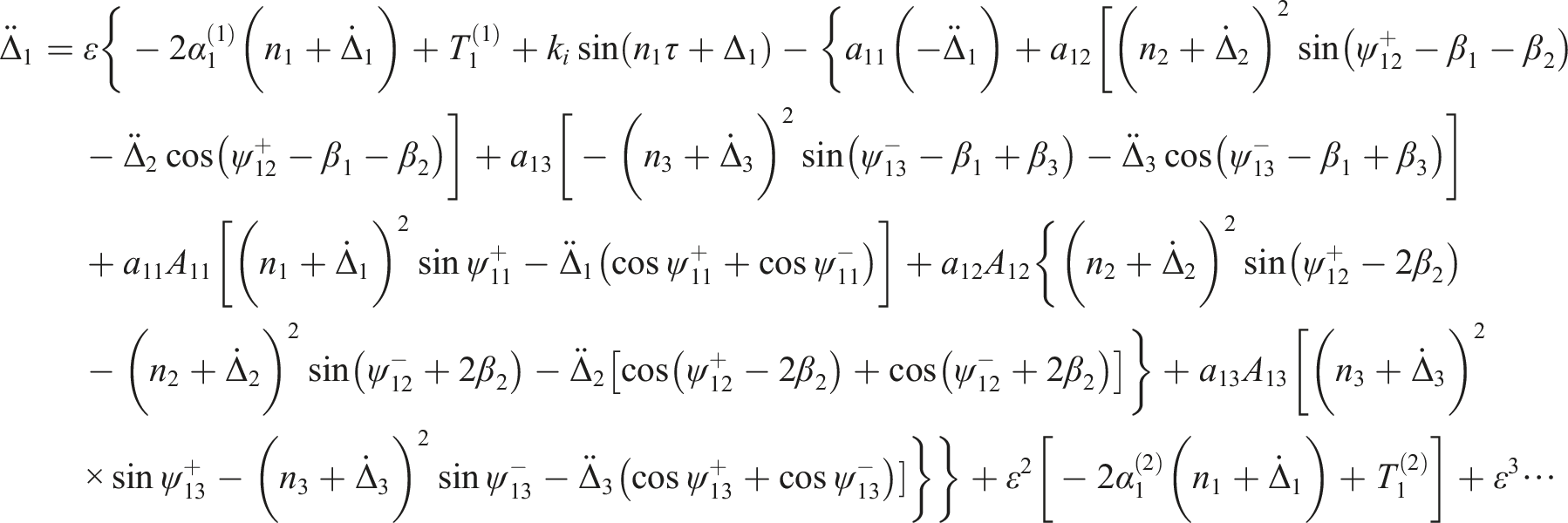
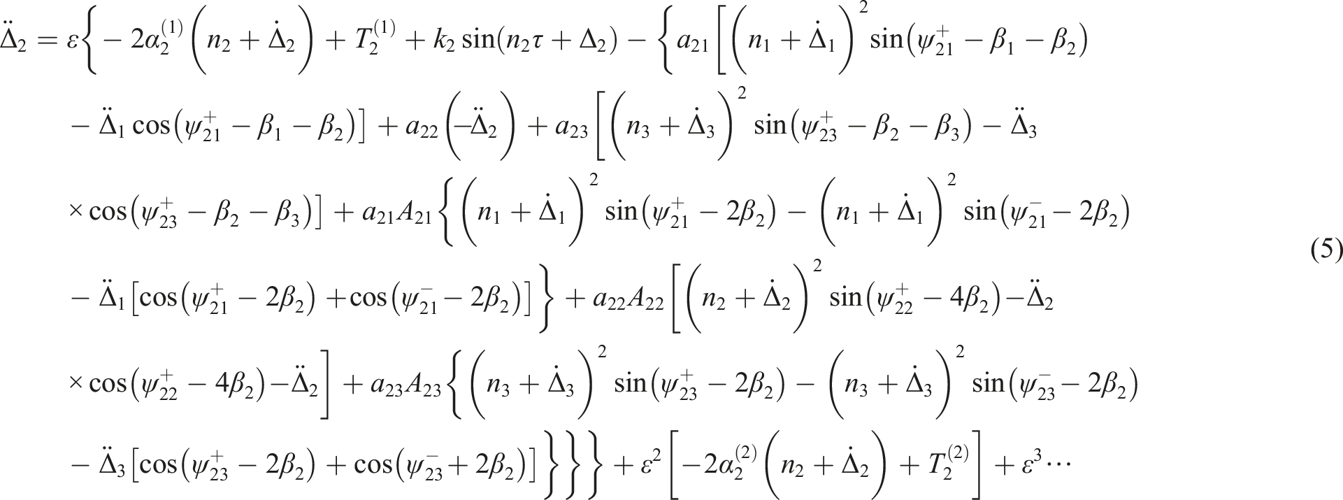
Substituting equation (4) into equation (2), and after the arrangement, yields
with
Here, equation (5) is the basic expression of the system to reach synchronization. Due to that equation (5) containing the small parameter is not a standard form, it is necessary to rearrange it into a Bogoliubov standard form by applying the asymptotic method,8,25 we assume
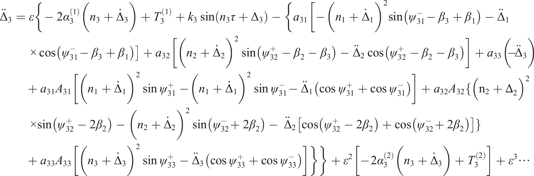
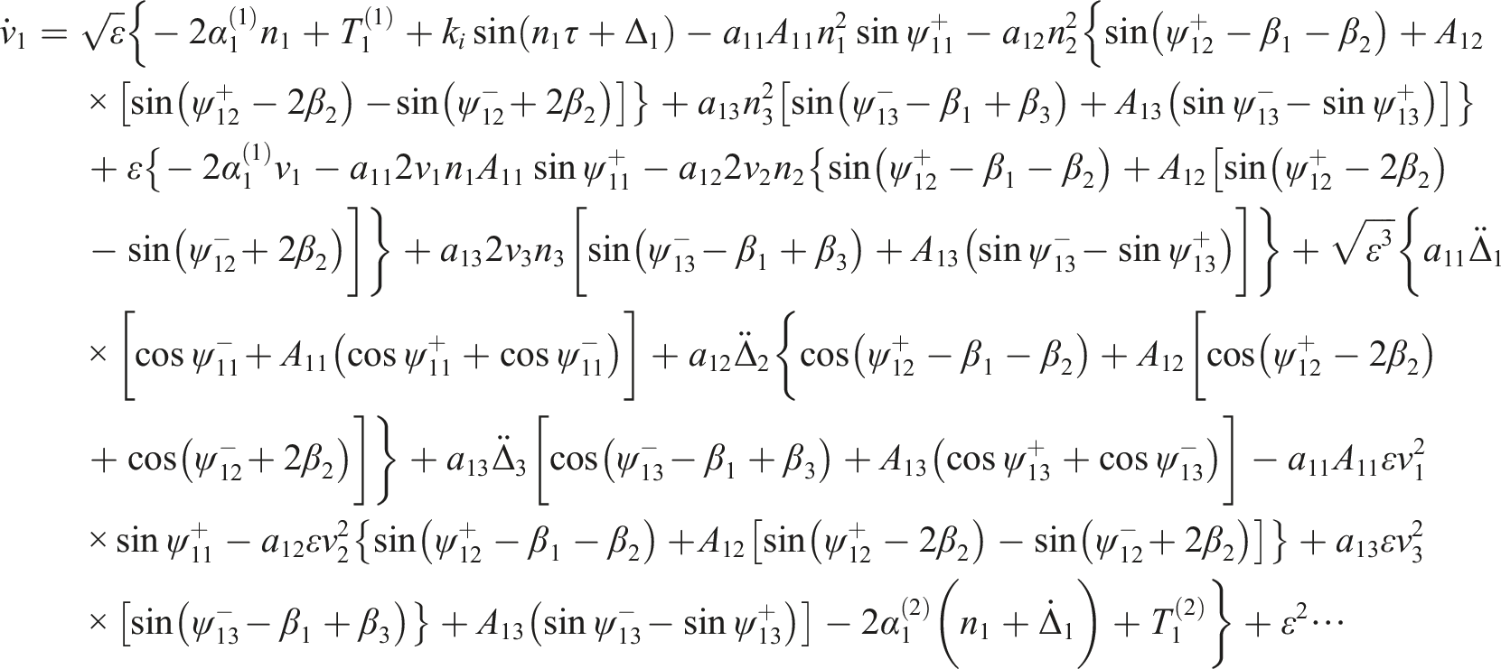
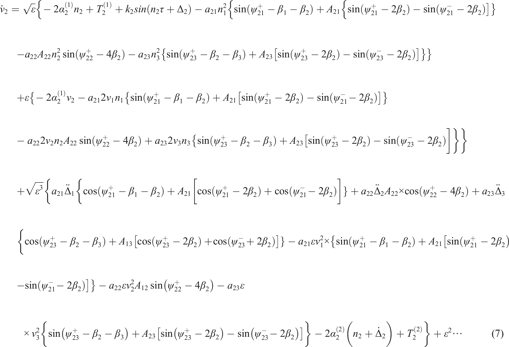
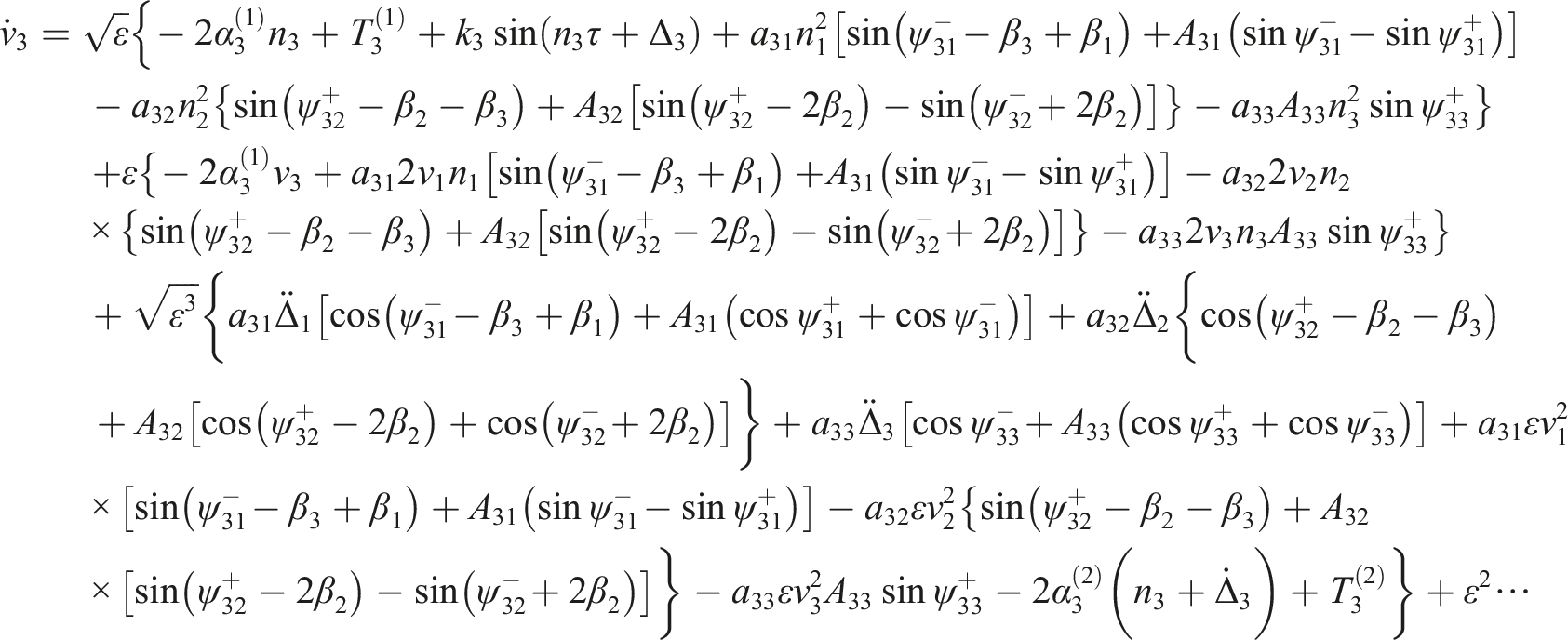
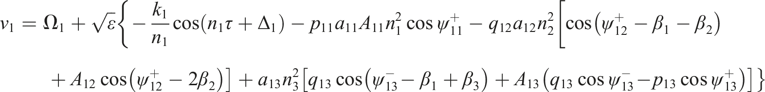
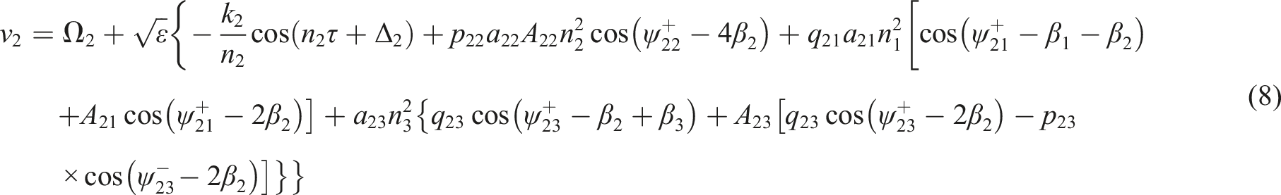
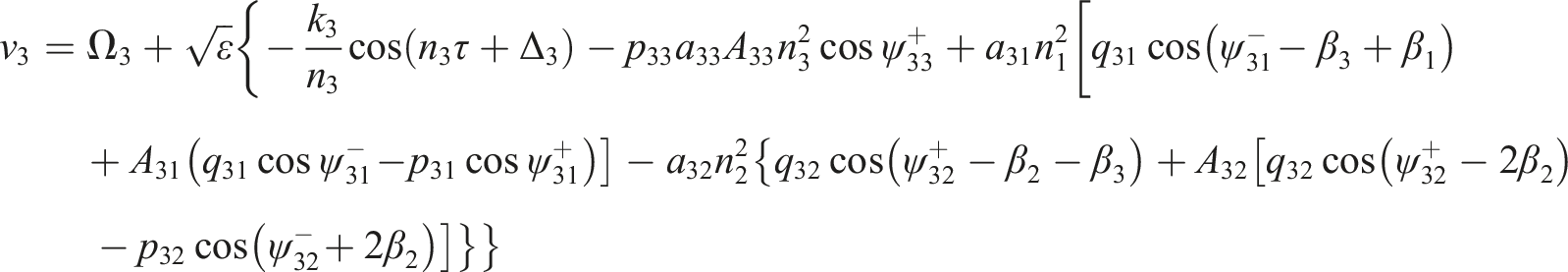
Differentiating equation (6) with respect to the dimensionless time to yield , which is inserted into the three formulae of equation (5), and after the rearrangement, the first-order differential equations are
It is not difficult to see that the derivative in equation (7) is proportional to the small parameter , thus is the slow-changing parameter. Based on the average method, can be represented as the superposition of the uniformly varying term and the sums of small oscillating terms,8,25 so the equations of improved first approximation of , can be obtained by
with
where denotes the direction coefficient, it is positive one for clockwise, otherwise, negative one for anticlockwise.
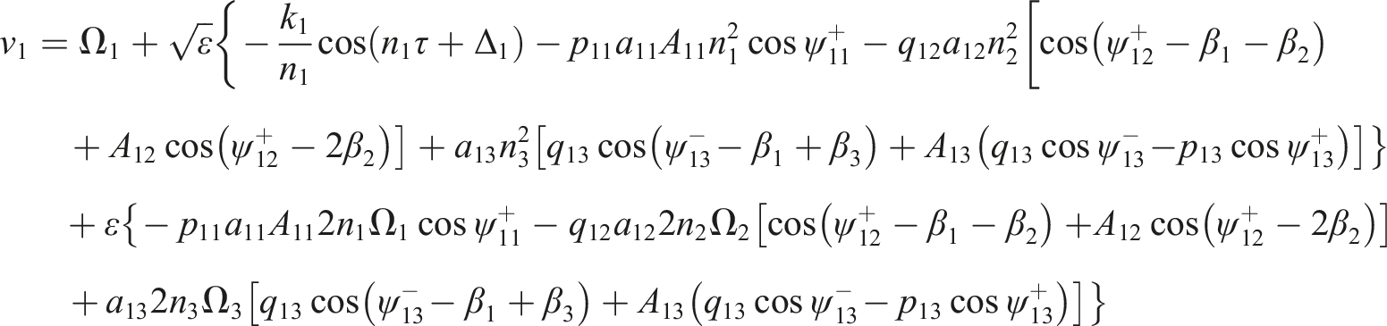
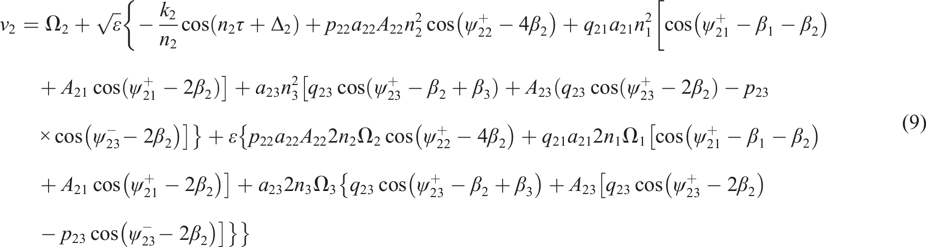
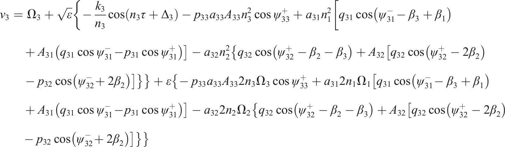
Similarly, the improved second approximate solutions of , are signified as follows
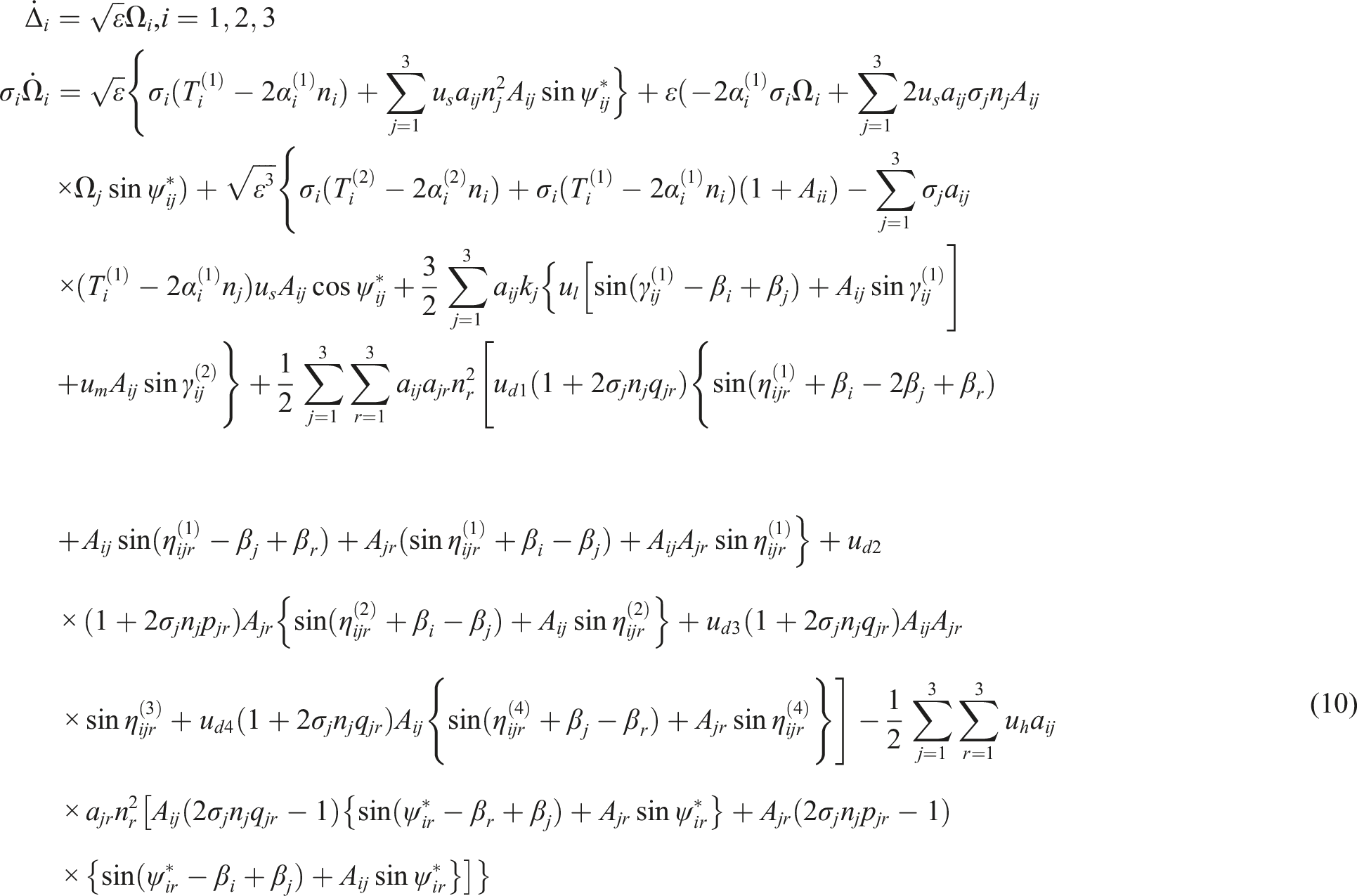
Since the influence of the small vibration terms on the systematic change of can be ignored, we can use the average value of to represent . Omitting the small oscillations, and substituting equation (9) into the right-hand sides of equal signs of equation (7), then integrating them over and the mean values are taken, provided further that the variables, and , are considered to remain constant during the above averaging process. Thus, the average differential equations of three exciters, can be obtained as
where
According to equation (10), if the three exciters implement the synchronous operation, then the mean values of and are zero.8 It should be noted that in the relevant terms of and , the expressions for synchronous phase relationships among exciters with the same rotational velocities can be determined, while the synchronous phase relationships among exciters with the rotational velocity ratio of 1:2 or 1:3, can be obtained from the relational terms of when or . In the following, some theoretical analyses on double/triple-frequency synchronization and their stabilities will be performed.
Synchronization of exciters with a frequency ratio of 1:1
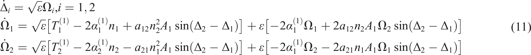
Since , the rotational velocities of exciters one and two are identical, that is, the synchronization between the two exciters with a frequency ration of 1:1, can be implemented, in this case, the terms of and in equation (10), can be expressed as
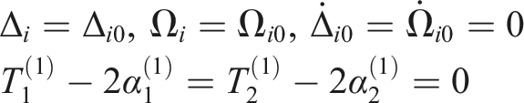
When the vibrating system operates in the synchronous state, we have
Combining equations (11) and (12), the condition of fundamental-frequency synchronization (i.e., the frequency ratio is 1:1) between the exciters one and two, is presented by
Synchronization of exciters with a frequency ration of 1:2
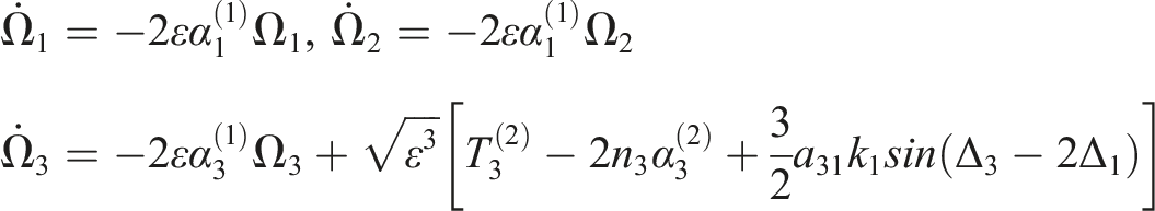
When and , the rotational velocity of exciter three is twice that of exciter 1 (or 2), that is, the double-frequency synchronization of the system can be realized. So, in equation (10), the items about can be simplified as
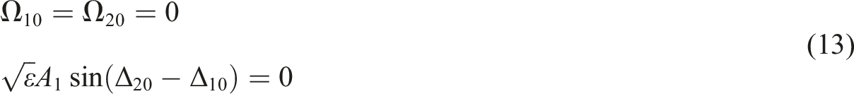
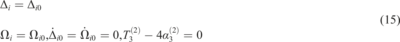
The following formulae are available when the three exciters operate synchronously
Taking equations (14) and (15) into consideration, the double-frequency synchronization criterion of the system can be directly given by
So equation (16) is the double-frequency synchronization criterion. In this case, generally the synchronous solutions for phase difference () have two different values, namely, and , of which only one of both is stable. In order to determine which one is the final stable state of system, it is necessary to further analyze the stability of system in the following.
For the purpose of obtaining the stable phase difference, it is assumed that the amounts of small perturbations in the steady state are and . Hence, we have
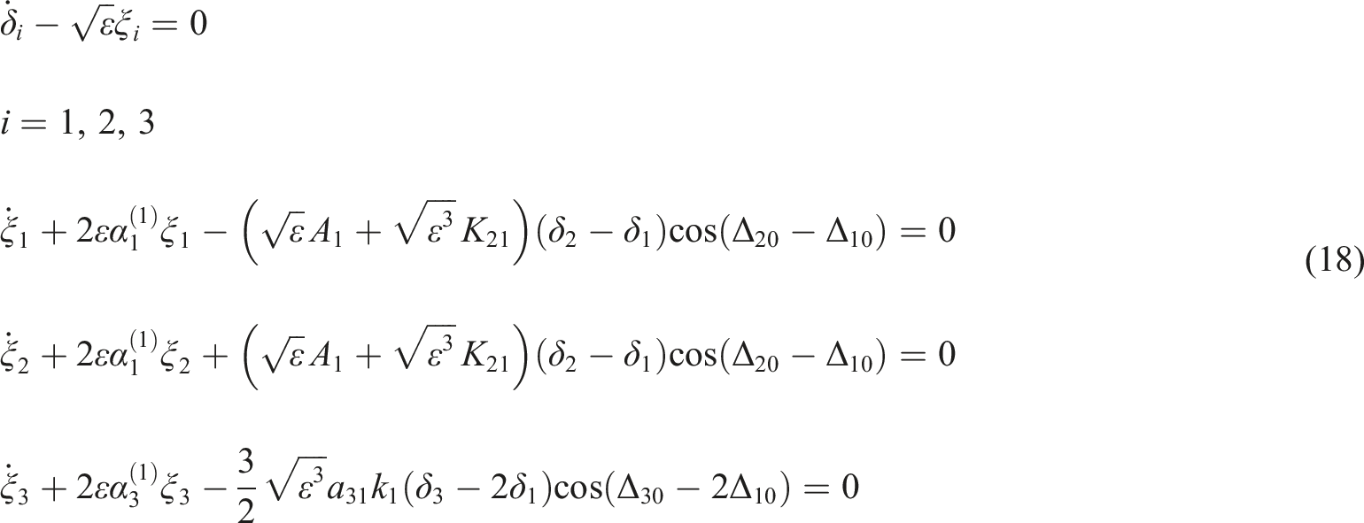
Substituting equation (17) into equation (10), the small deviation equations of the system, can be derived as
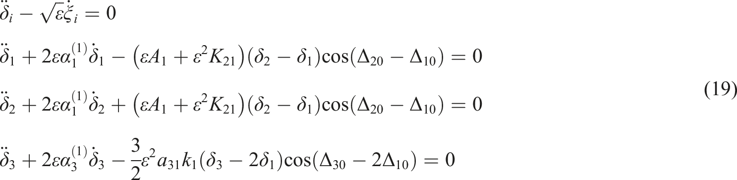
The rearrangement of four formulae in equation (18), yields the expressions with regard to , that is
with
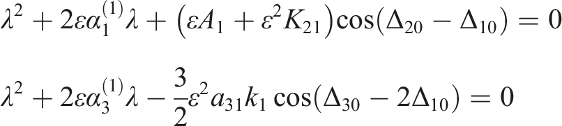
The corresponding characteristic equations for eigenvalue λ, can be obtained as
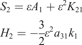
Based on the Routh–Hurwitz criterion, only if all the roots of eigenvalue have the negative real parts, can the solutions on the phase differences among the three exciters be stable. So the stability criterion of the double-frequency synchronization states, can be presented in form
with
where is defined as the coefficient of stability ability for the fundamental-frequency synchronization, and is defined as that for the double-frequency synchronization. Additionally, in engineering, the small parameter has the relationship of , and these dimensionless parameters , , , and are all greater than zero, thus we have and . From equation (21), one can obviously see that the phase differences are stabilized in the interval of and .
When the system realizes the double-frequency synchronization, combining the synchronization criterion equations (13) and (16) above, the stable phase differences among the three exciters, can be determined as
Synchronization of exciters with a frequency ration of 1:3
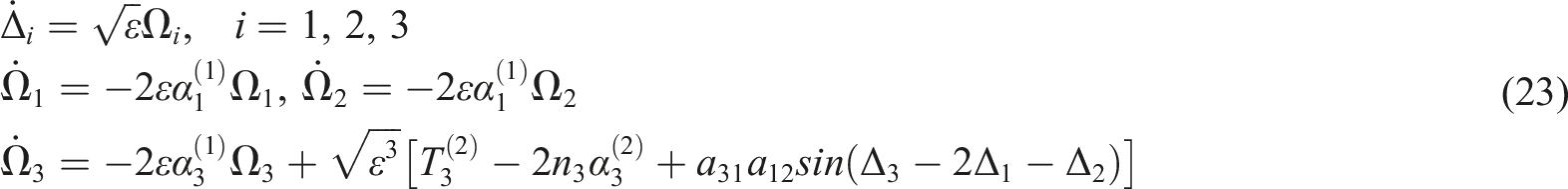
When and , the steady rotational velocity of exciter three is three times that of exciter one (or two). In this case, the vibrating system can implement the triple-frequency synchronization. Taking the relevant items of in equation (10), the following relationships can be obtained
According to equation (23), when the system is in the steady state, the triple-frequency synchronization criterion can be described as
In equation (24), there are two situations for the synchronous solutions of stable phase differences among exciters with a frequency ration of 1:3, namely, and , but not all of them are stable, which one is stable? It depends on the following stability criterion.
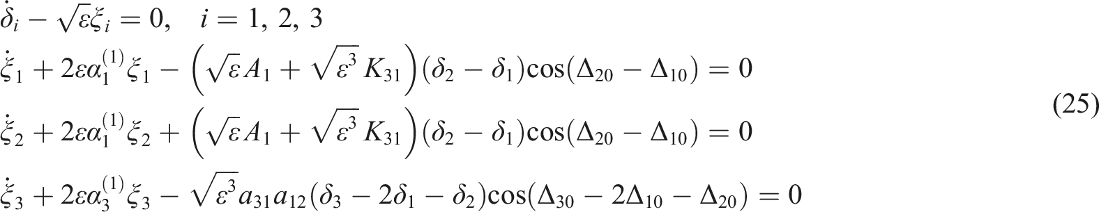
For the sake of obtaining the stable phase differences, similar to the double-frequency synchronization analysis method in Synchronization of exciters with a frequency ration of 1:3, the perturbation differential equation expressions of the system in the steady state, are established as
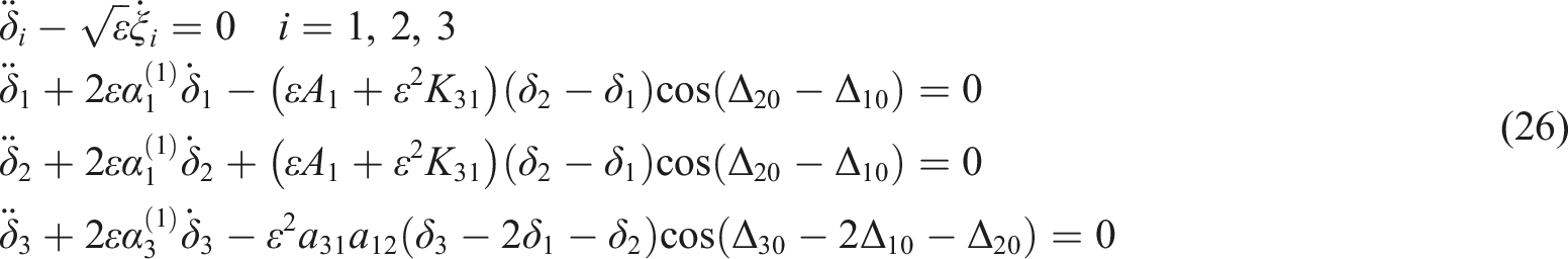
Rearranging equation (25), we arrive at the equations with regard to in form
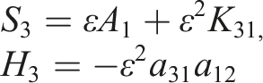
with
The characteristic equations for eigenvalue λ can be obtained as
All roots of λ in equation (27) should have negative real parts in order to guarantee the fact that the system is stable. By applying the Routh–Hurwitz criterion, equation (28) can be obtained to satisfy the above requirements
with
Thus, the stability criterion for three exciters to achieve the triple-frequency synchronous state, is equation (28). Here, is defined as the coefficient of stability ability for fundamental-frequency synchronization, while is defined as that for the triple-frequency synchronous state. Considering the synchronization criterion equations (13) and (24), when the system achieves the triple-frequency synchronization, the stable phase differences are expressed as
Numerical qualitative analyses on stability characteristics
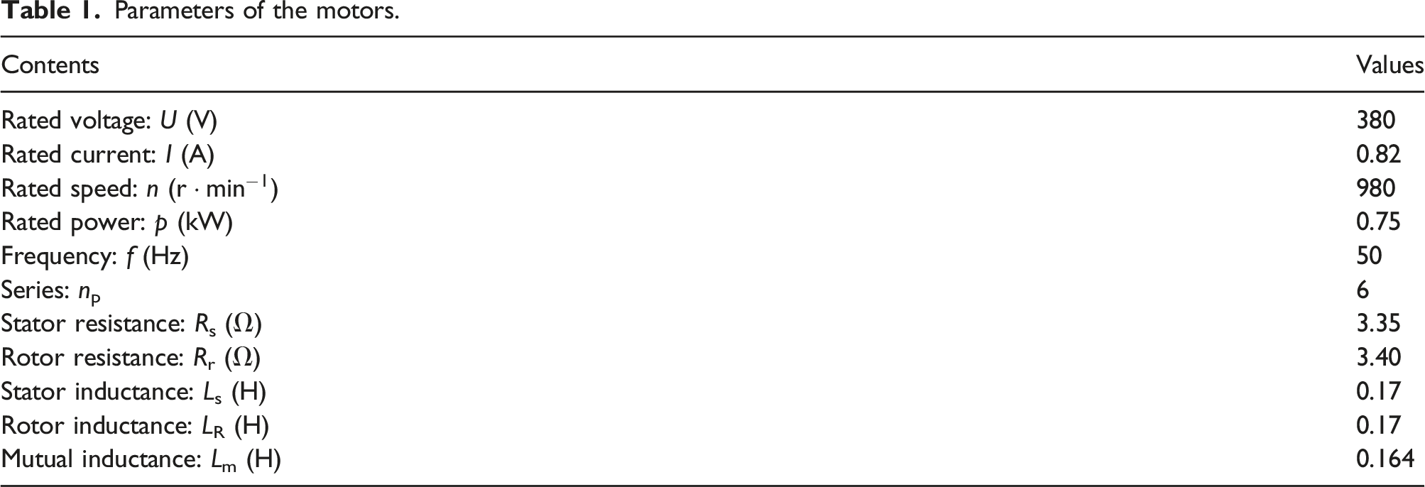
Based on the previously derived theoretical results, in this section, the numerical analyses are carried out to qualitatively reveal the stability characteristics of the system, and the masses of exciters are set as: (, is the mass of standard exciter). The parameters of three motors are listed in Table 1. The system parameters: , , , , , , , , , , and . According to the given parameters, the natural frequencies of the system can be calculated as: .
Parameters of the motors.
Contents
Values
Rated voltage: U (V)
380
Rated current: I (A)
0.82
Rated speed: n ()
980
Rated power: p (kW)
0.75
Frequency: f (Hz)
50
Series: np
6
Stator resistance: Rs (Ω)
3.35
Rotor resistance: Rr (Ω)
3.40
Stator inductance: Ls (H)
0.17
Rotor inductance: LR (H)
0.17
Mutual inductance: Lm (H)
0.164
In order to investigate the stability of the system under the different times-frequency synchronization conditions, it is necessary to introduce the dimensionless parameter , here the corresponding expression of versus and , is given first by
where , .
According to the expression of , its maximum value can be presented by
As indicated in Figure 2, one can see that the value of is not more than 12 for and , so the following discussions are preconditioned by .
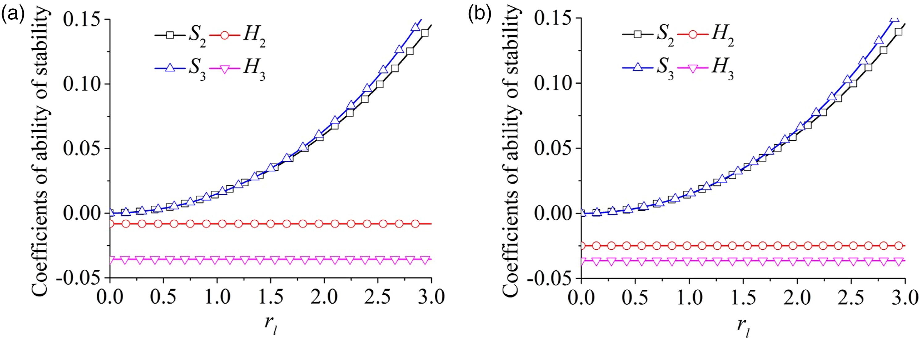
To reveal the stability level among the three exciters, substituting the above relevant system parameters into the expressions of equations (21) and (28), the curves of stability ability coefficients versus dimensionless parameter for different values of , , and (i = 2,3), are obtained. As shown in Figure 3, the fundamental-frequency stability ability coefficients, and , increase with the increasing , while the times-frequency stability ability coefficients, and , do not change with the increase of . From Figure 3(a) and (b), it can be seen that the values of and are always greater than 0, while the opposite is true for the values of and , which indicates that there is only one synchronous stability region of the system under fundamental and times-frequency conditions, respectively. As a consequence, the phase relationship in the steady state is due to the facts of and , while for and . Furthermore, under the condition of changing the mass of exciter 3, it is found that the changing trend of the stability ability coefficients is independent of mass of exciter 3.
Coefficients of stability ability of the system: (a) ; (b) .
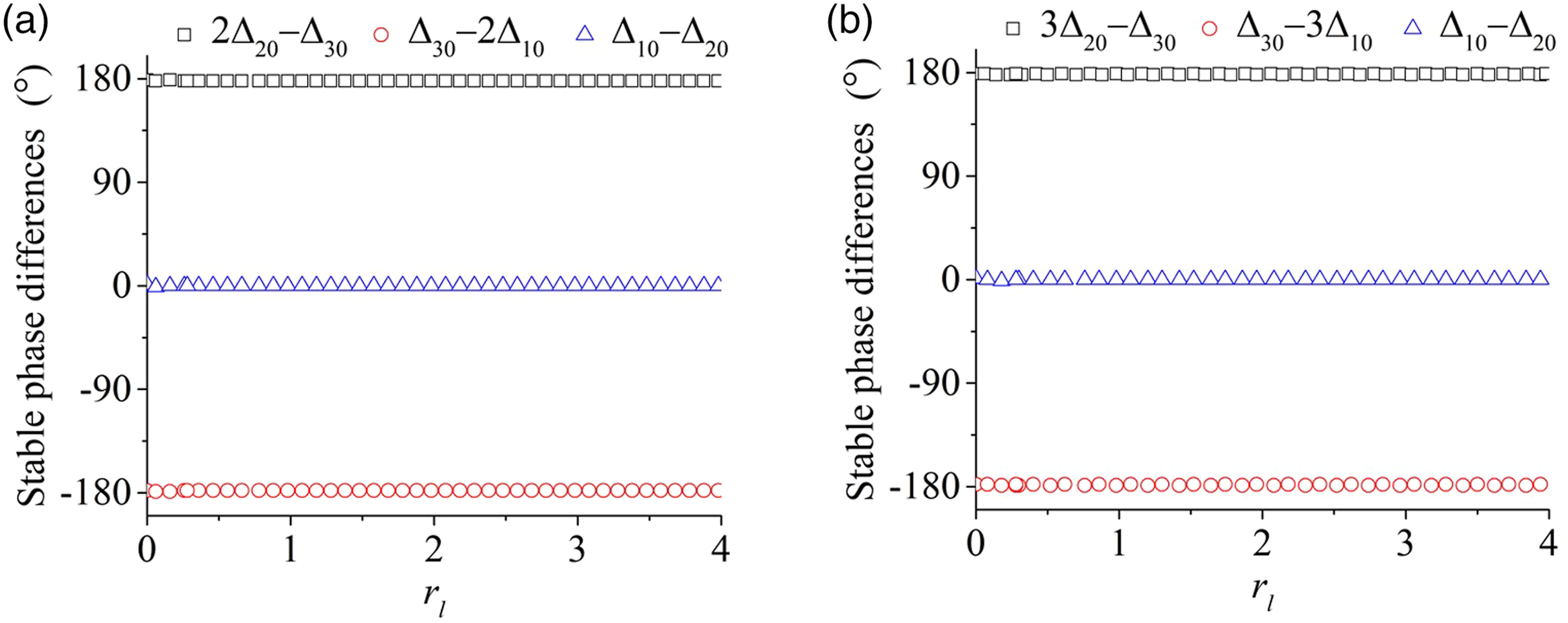
Based on the synchronization criterion equations (13), (16), and (24), and the stability criterion equations (21) and (28), the relationship curves of stable phase differences among the three exciters with the different frequency ratios and , can be obtained, as plotted in Figure 4. One can see that the stable phase differences remain unchanged when the system is in the steady state, indicating that the mounting distance between rotational center of exciter three and centroid of the system has little effect on the change of stable phase differences. As shown in Figure 4, and hold for the fact that the phase difference for the fundamental-frequency synchronization, , is stabilized in the vicinity of 0; while for and , which corresponds to the phase difference for the times-frequency synchronization, is stabilized in the neighborhood of . These results can comply with the stability criterion well.
Stable phase differences versus : (a) double-frequency; (b) triple-frequency.
The above numerical qualitative analytical results for the system stability, can be further validated by the following simulations and experiments.
Simulations
In this section, in order to further analyze and validate the above theoretical and numerical qualitative results, some corresponding simulations are performed by directly applying a fourth-order Runge–Kutta routine to the motion differential equations of the system equation (1). The parameters of the system and motors are listed in Numerical qualitative analyses on stability characteristics. The detailed simulation results, including the double-frequency and triple-frequency synchronization for three exciters, are obtained by changing the operating frequency of exciters.
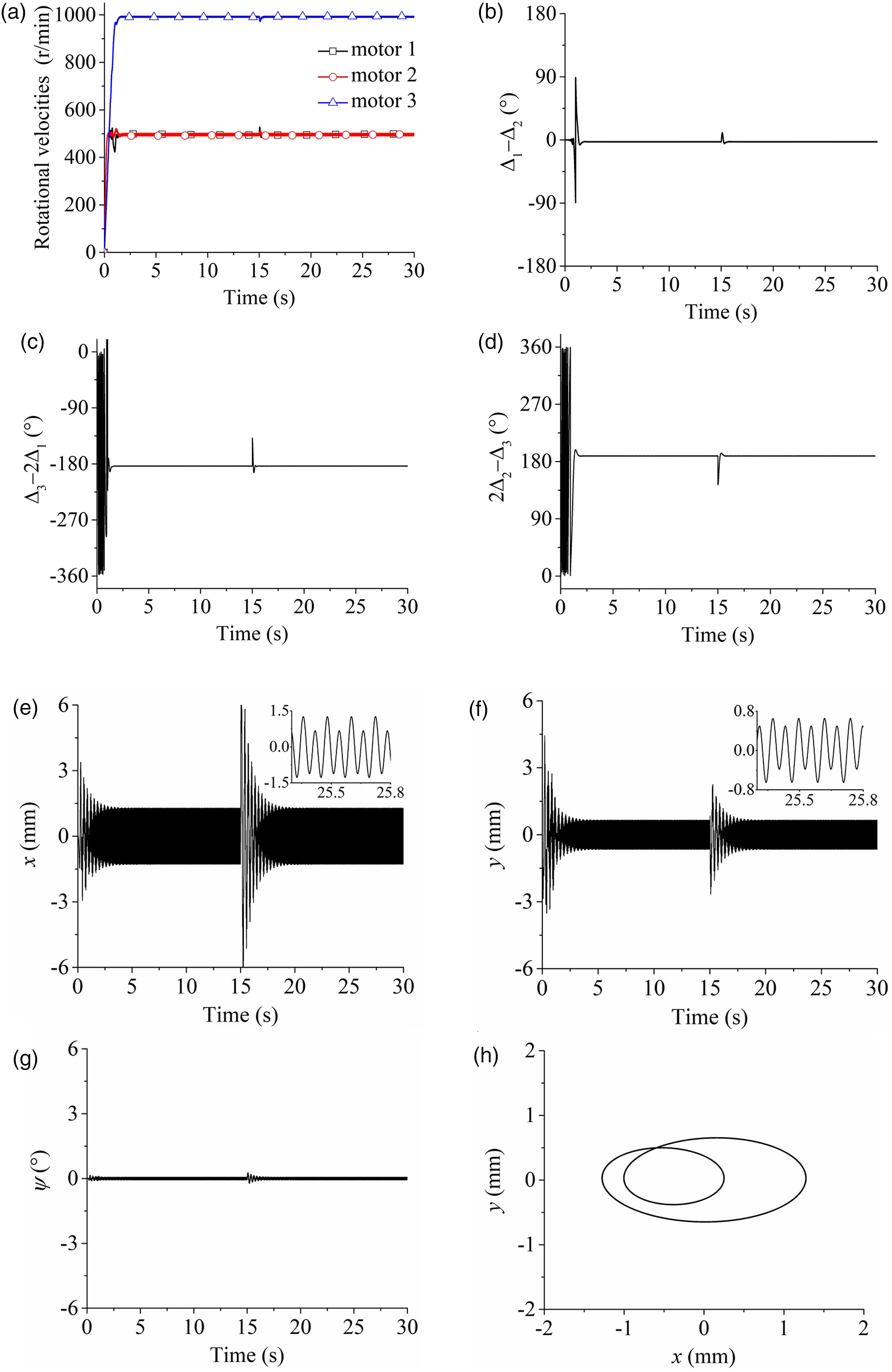
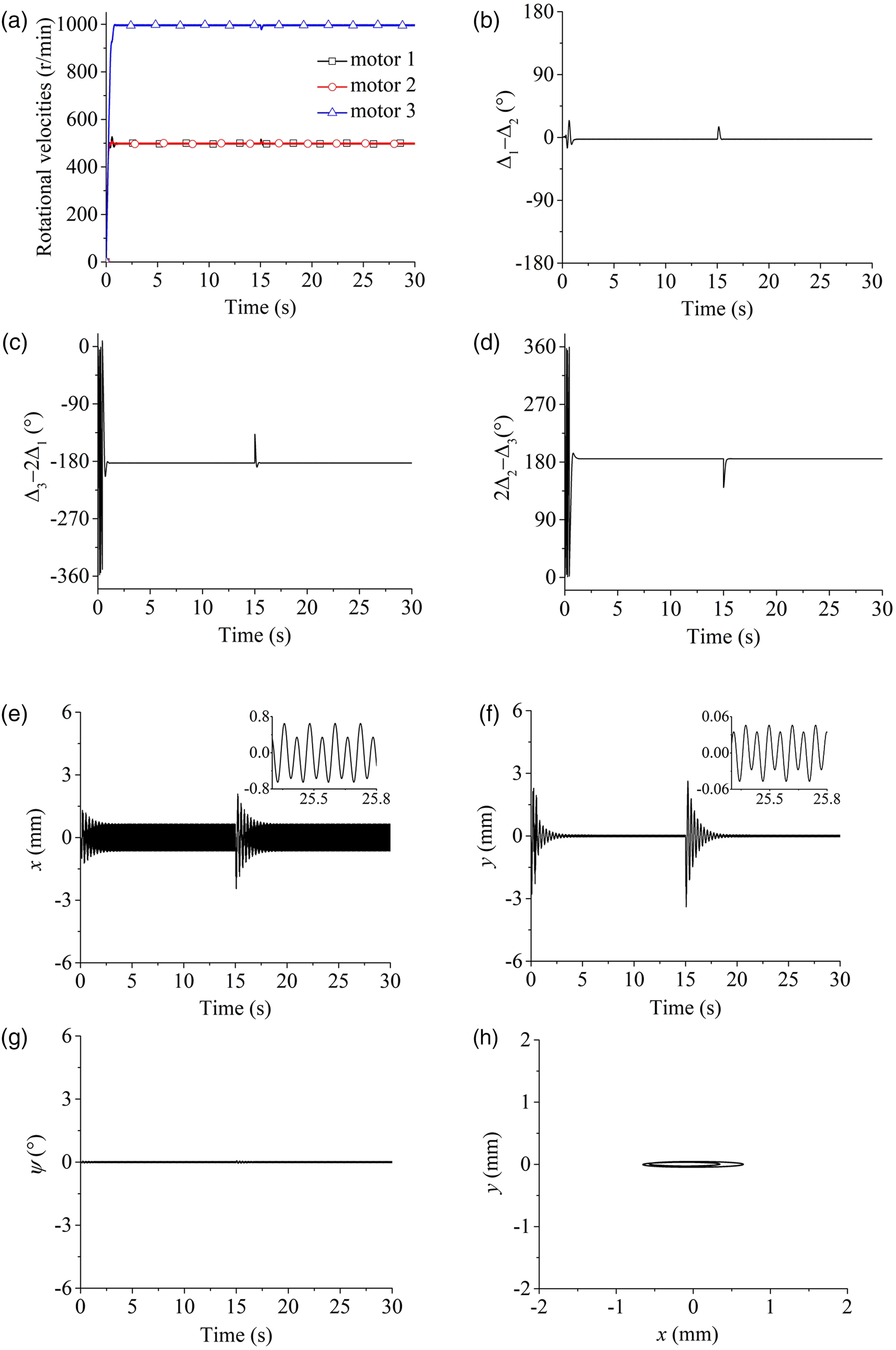
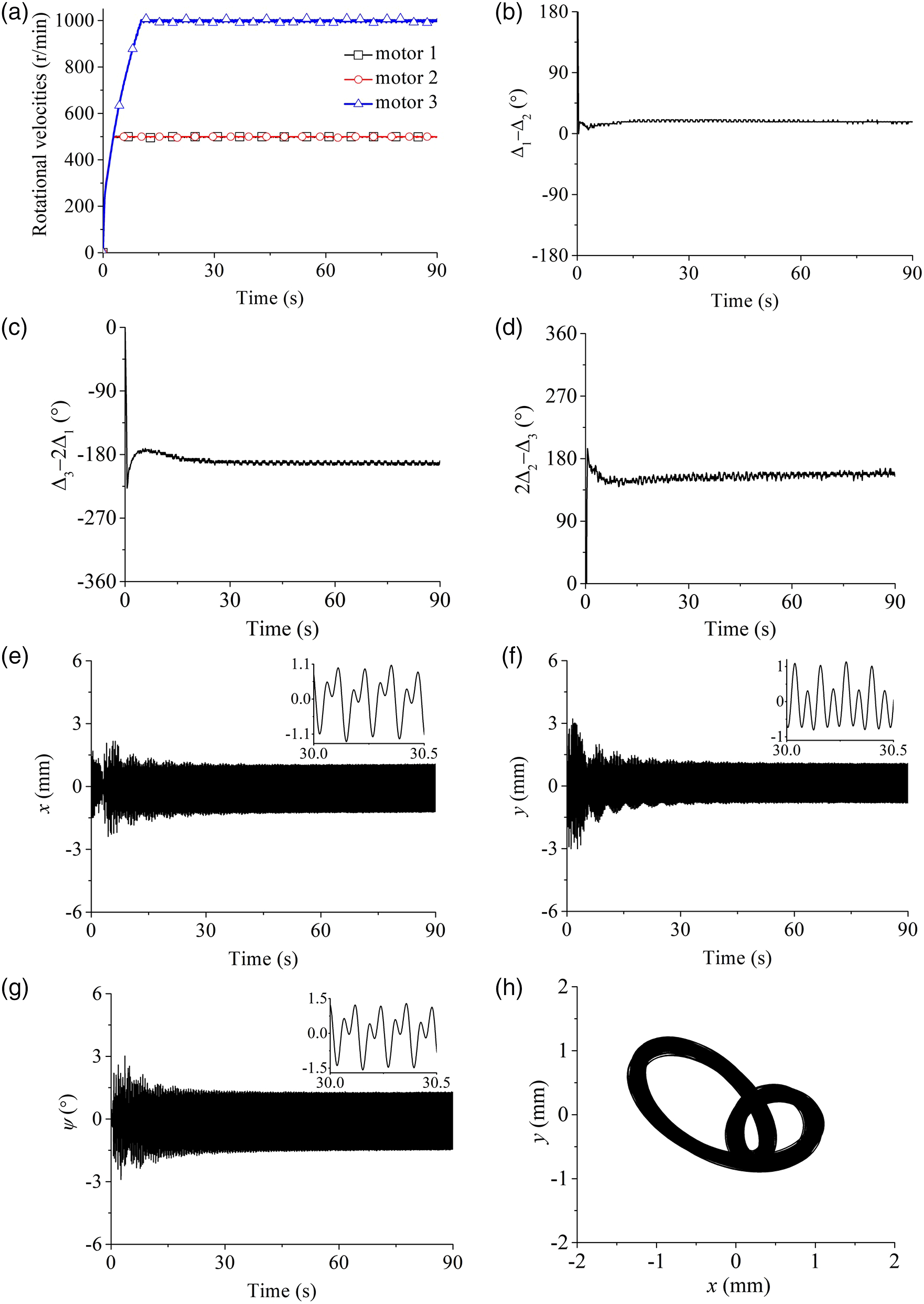
Figure 5 shows the simulation results of the double-frequency synchronization for , and here . The operating frequencies of motors one and two are set as 25 Hz and the motor 3 as 50 Hz. As demonstrated in Figure 4(a), the synchronous rotational velocities of motors 1 and 2, are stabilized around 498 r/min, and that of motor three is about 996 r/min, that is, rad/s > , at this moment, the vibrating system operates in the far super-resonant state. At about 2s, the system implements the double-frequency synchronization. In the synchronous and steady state, the values of phase differences are stabilized in the vicinity of , and , these facts are well in agreement with what is shown in Figure 4(a). Besides, a disturbance of phase is added to the exciter three at 15s, the phase difference curve quickly returns to its original stable state after a short fluctuation period, which indicates the system has relatively strong stability.
Double-frequency synchronization simulation results : (a) rotational velocities of the three exciters; (b) phase difference between exciters one and two; (c) phase difference between exciters one and three; (d) phase difference between exciters two and three; (e) displacement in x-direction; (f) displacement in y-direction; (g) displacement in ψ-direction; and (h) motion trajectory of the mass center for the rigid frame.
Figure 5(e) and (g) illustrate the displacement responses of the rigid frame in x-, y-, and -direction. It can be seen that the vibration amplitudes of the rigid frame in x- and y-direction are 1.28 mm and 0.65 mm, respectively, the swing angle is close to 0. And the system can implement the double circular motion trajectory similar to the inner “8” glyph, as shown in Figure 5(h). According to the enlargement diagram, we know that the vibration waveform is not a simple harmonic shape but a vector superposition of two different harmonics when the vibrating system reaches synchronous stability under the times-frequency conditions. This is because the low-frequency and high-frequency motors can generate different exciting forces that interact and influence each other, which in turn leads to a superimposed wave in the displacement response.
By changing the mass relationship of exciters to be and , the mass moments of three exciters are , the simulation results are obtained as shown in Figure 6. When the three motors are supplied with the electric source simultaneously, the system reaches synchronous and stable state after about 2s. As shown in Figure 6(a), in the steady state, the rotational velocities of motors one and two are basically stable by 498 r/min, and that of motor three is close to 996 r/min, that is, the ratio of rotational velocities between the low-frequency and high-frequency motors is 498/996 = 1/2, which indicates that the system achieves the double-frequency synchronization. At about 15s, a disturbance of phase is added to the motor three in order to examine the stability of system. According to the curves in Figure 6(b)-(d), it is obvious that the phase relationships among exciters are stabilized in the neighborhood of , , and . From the partial enlargements of displacement response in Figures 6(e) and (f), it can be found that the vibration amplitudes of the rigid frame are 0.65 mm and 0.046 mm, respectively, in x- and y-directions, and the swing angle in Figure 6(g) is so small that it can be ignored.
Double-frequency synchronization simulation results : (a) rotational velocities of the three exciters; (b) phase difference between exciters one and two; (c) phase difference between exciters one and three; (d) phase difference between exciters two and three; (e) displacement in x-direction; (f) displacement in y-direction; (g) displacement in ψ-direction; and (h) motion trajectory of the mass center for the rigid frame.
Compared with the simulation results under the condition of , the changes of stable phase differences are very small, which indicates that the mass moment of the exciter 3 has little effect on the phase difference of the system. While the displacement of the rigid frame, especially that in y-direction, embodies an apparent decrease with the decreasing unbalanced mass moment of the exciter three.
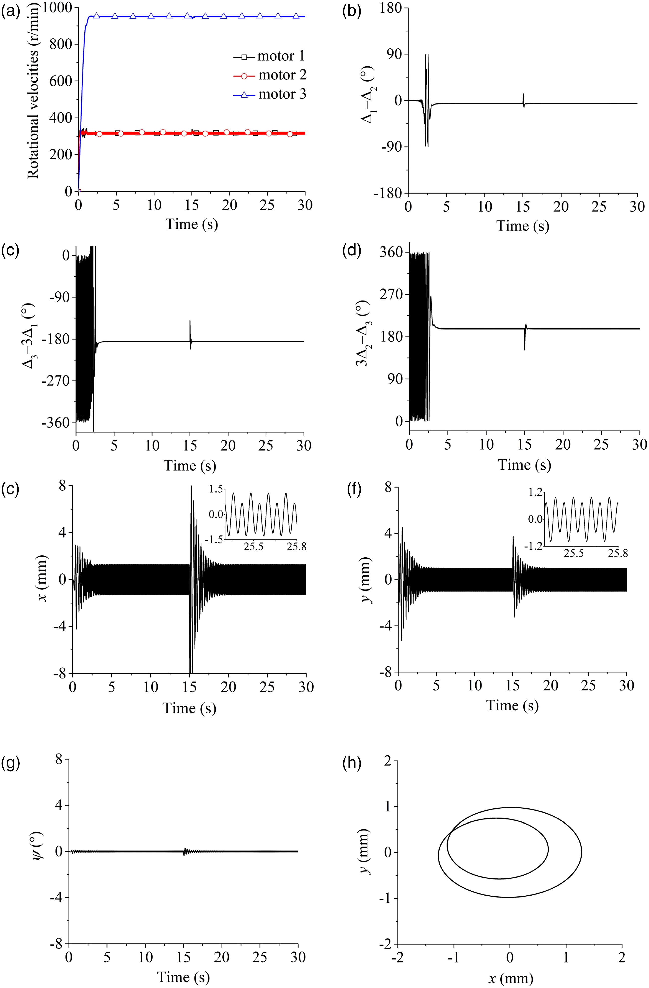
The frequencies of exciters one and two are set to be 16 Hz and that of exciter 3 to 48 Hz by adjusting the power supply frequency of three motors. The triple-frequency synchronization simulation results for , are given as Figure 7. From Figure 7(a), the rotational velocities of motors one and two are stabilized about 320 r/min and that of motor three is around 960 r/min, that is, the operating frequency is , this indicates that the system is operating in a far super-resonant condition. As shown in Figure 7(b)-(d), the phase differences among three exciters are stabilized about , , and , which are well consistent with the results in Figure 4(b). At 15s, due to that the exciter three is added an interference, the phase difference curves occur a slight fluctuation, and then return to their previous stable states quickly. Moreover, during the simulation process, the stability value of the system will not change no matter how large the given perturbation is, which shows the stronger stability of the system. As plotted in Figure 7(e)-(g), the vibration amplitudes of the rigid frame are 1.27 mm and 1.0 mm, respectively, in x- and y-directions, and the corresponding motion trajectory is shown in Figure 7(h).
Triple-frequency synchronization simulation results : (a) rotational velocities of the three exciters; (b) phase difference between exciters one and two; (c) phase difference between exciters one and three; (d) phase difference between exciters two and three; (e) displacement in x-direction; (f) displacement in y-direction; (g) displacement in ψ-direction; and (h) motion trajectory of the mass center for the rigid frame.
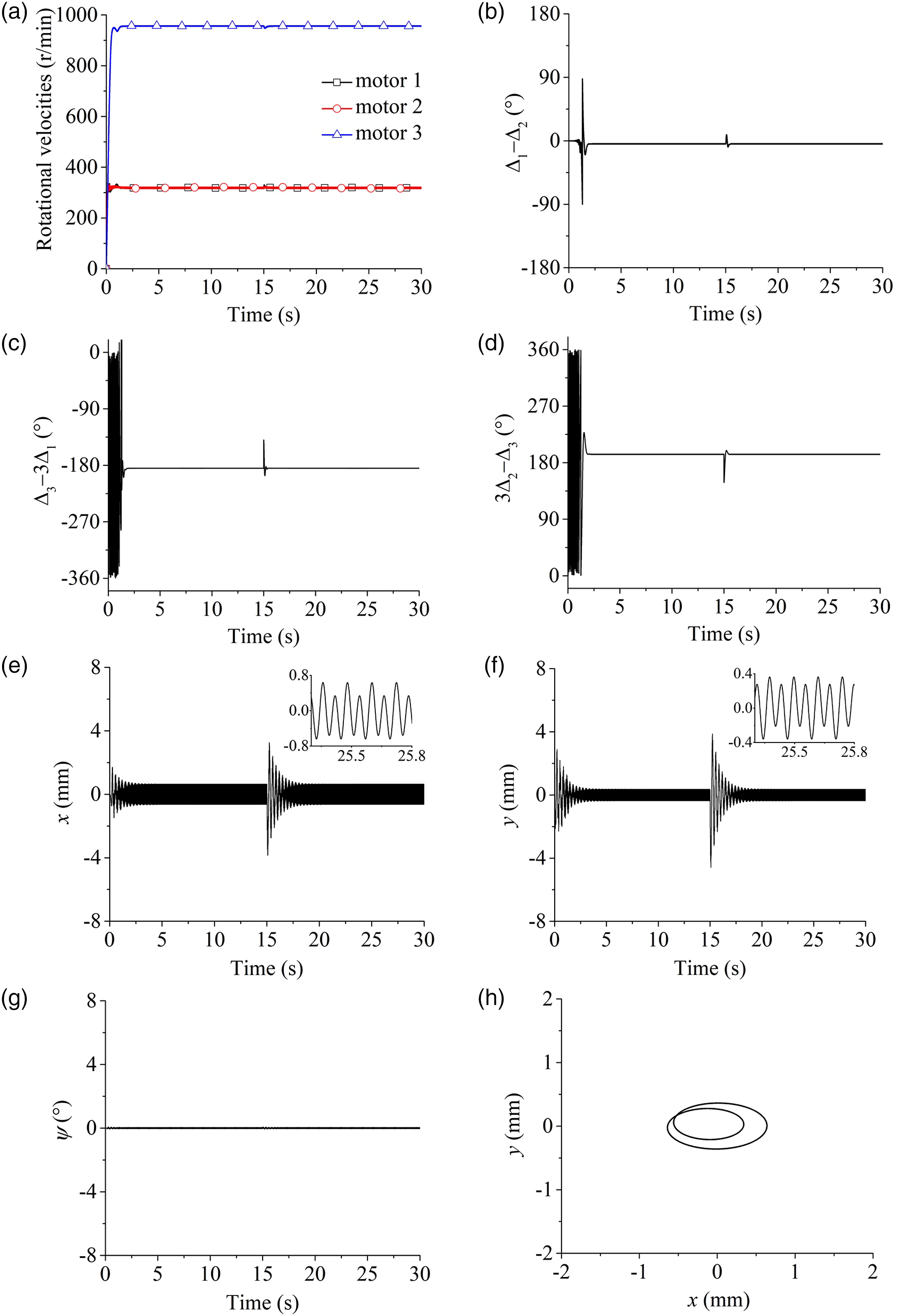
The simulation results of triple-frequency synchronization for , are illustrated in Figure 8. In Figure 8(a)-(d), the synchronous and stable states of the system: the synchronously rotational velocities of motors one and two are 319 r/min and that of motor three is 957 r/min, the operating frequency ratio is 319.0/957 = 1/3, which indicates that the system can implement the triple-frequency synchronization, and the stable phase differences are about , , and . As shown in Figure 8(e)-(h), the responses in x- and y-directions are the high and low harmonic vibrations with the amplitudes of about 0.64 mm and 0.36 mm. From the motion trajectory of the rigid frame in Figure 8(h), it can be seen that the range of motion is reduced. This is because that the reduced mass moment of the exciter 3, decreases the displacement of the rigid frame in all directions.
Triple-frequency synchronization simulation results : (a) rotational velocities of the three exciters; (b) phase difference between exciters one and two; (c) phase difference between exciters one and three; (d) phase difference between exciters two and three; (e) displacement in x-direction; (f) displacement in y-direction; (g) displacement in ψ-direction; and (h) motion trajectory of the mass center for the rigid frame.
In summary, the simulation results are roughly consistent with the numerical qualitative analyses in Numerical qualitative analyses on stability characteristics, there are slight deviations in the simulation results of the stable phase differences on account of the damping influence of the system, but they are all within a reasonable range, and the simulation results all satisfy the stability criterion equations (21) and (28).
Experimental verifications
In this section, it is essential to perform some corresponding experimental verifications in order to further validate the above theory, numeric, and simulation results.
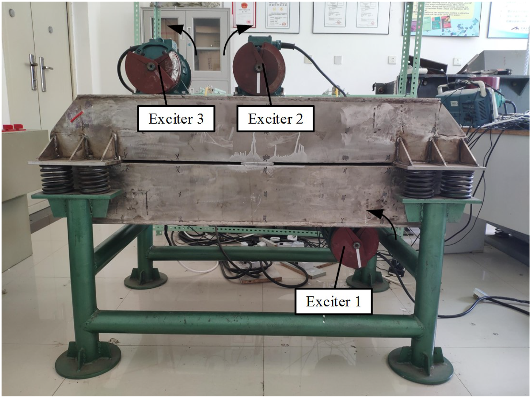
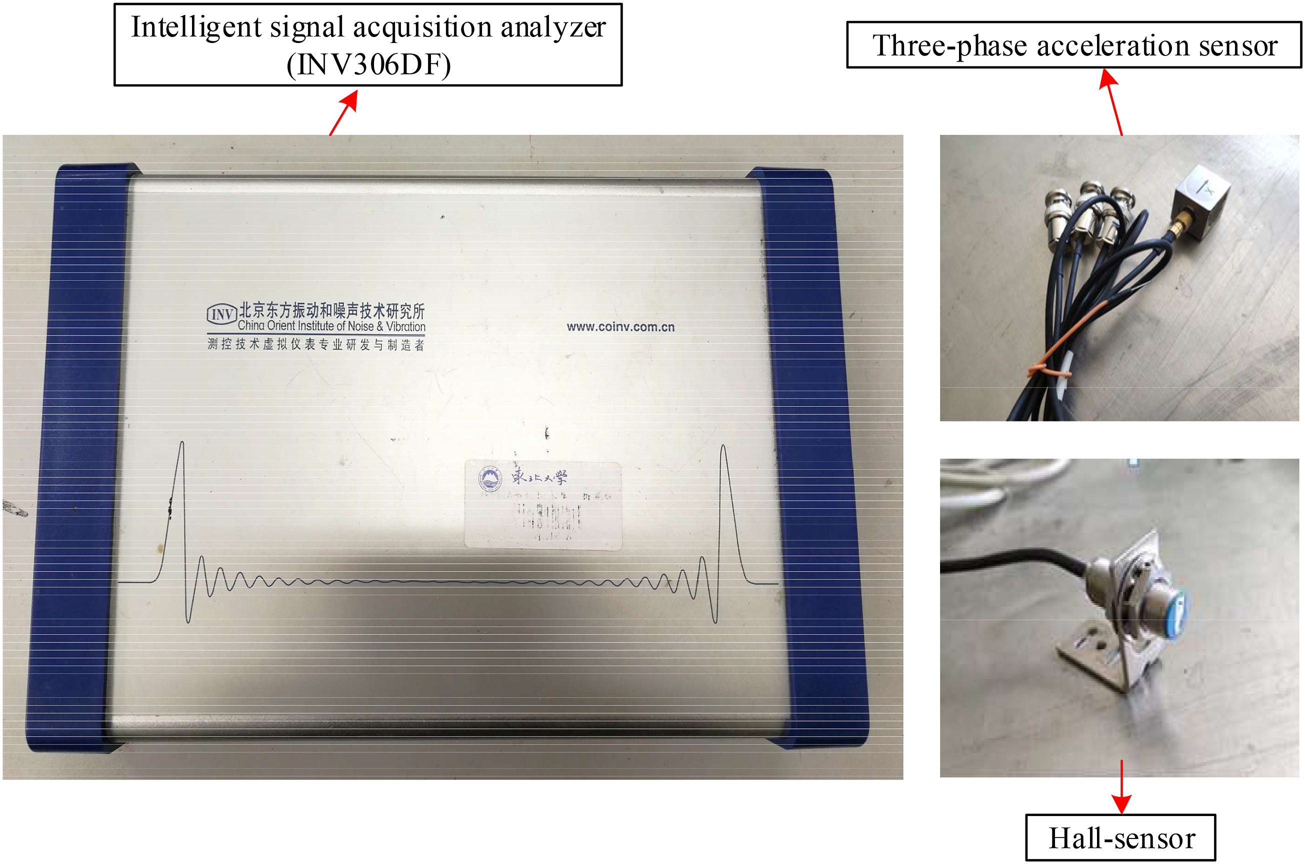
It should be noted that, since the maximal rated rotational velocity of the vibrating motors (i.e., exciters) being available in the laboratory, does not exceed 1000 r/min, and the vibrating motors with higher rated rotational velocity are required for verifying triple-frequency synchronization. Therefore, only some experimental results for the double-frequency synchronization are given in this section. The experimental devices include vibratory synchronization bedstand and corresponding testing instruments, as shown in Figures 9 and 10.
Vibratory synchronization bedstand.
Testing instruments on double-frequency synchronization experiment.
As demonstrated in Figure 9, the exciters two and three are installed on the upper side of the rigid frame, the exciter one is distributed on the lower side of the rigid frame, and the rotating directions of the exciters one and three are opposite to that of the exciter two. In Figure 10, the three-phase acceleration sensors are employed to measure the acceleration signals of the vibratory synchronization bedstand in x-, y-, and -directions, and three Hall sensors are used to measure the phases of three exciters, respectively. Meanwhile, the intelligent signal acquisition analyzer (INV306DF) records the test date during the experiment process, then imports them into the Matlab software for program processing, and finally imaged through Originpro eight.
Before the experiment system operates, the frequency of the power supply to each motor can be adjusted by the frequency converter to obtain different frequency ratios, and the operating frequencies of the three motors are set to be 25 Hz, 25 Hz, and 50 Hz, respectively. The exciting force of each exciter can be determined by adjusting the angle between the two unbalanced blocks on both end sides of the vibrating motors. Generally, the greater the angle, the greater the exciting force. The three vibrating motors (so called exciters) used in the experiment are identical, the specific parameters of the motors are shown in Table 1, and the other experimental system parameters are: , , , , , , , , and . According to the above given parameters, we can calculate the natural frequencies of the system as and .
Figure 11 shows the corresponding experimental results of double-frequency synchronization. During the starting process, the power supply is simultaneously supplied to the three vibrating motors, and within the initial seconds, the three exciters excite the resonant responses when the rotational velocities pass through the resonant regions of the system, at this point, the system vibrates most intensely and has the largest amplitude. Under the action of damping, the resonant responses will gradually disappear and the vibrating system eventually reaches a stable state of double-frequency synchronization. As illustrated in Figure 11(a), the synchronous rotational velocities of motors one and two are stable to be 499 r/min, and that of motor three to be 998 r/min. Since the supply frequency ratio of low-frequency and high-frequency motors is set as 1:2, the rotational velocities show a corresponding relationship. At this time, the operating frequency , which means that the system is operating in a far super-resonant state. In Figure 11(b)-(d), the phase differences gradually tend to be stable after the initial stage of fluctuation, and the phase relationships among three exciters in the steady state are: , , and , respectively.
Double-frequency synchronization experimental results : (a) rotational velocities of the three exciters; (b) phase difference between exciters one and two; (c) phase difference between exciters one and three; (d) phase difference between exciters two and three; (e) displacement in x-direction; (f) displacement in y-direction; (g) displacement in ψ-direction; and (h) motion trajectory of the mass center for the rigid frame.
The displacement response curves of the rigid frame in x-, y-, and -directions are demonstrated in Figure 11(e)-(g), from which we can see the amplitudes of the rigid frame in the x- and y-direction are 1.16 mm and 0.94 mm, respectively, and the swing angle is about . According to the partial enlargement in Figure 11(e)-(g), it can be found that the waveform produced by the system under the double-frequency state, is a vector superimposed waveform, and the shape and amplitude of the superimposed waveform are stable with periodic changes. Compared to the simple harmonics generated by single-frequency vibration, the superimposed waves make the motion trajectory of the rigid frame more complicated, such as double elliptic motion approximately being as an inner “8” in Figure 11 (h). From the experimental results above, the vibrating system achieves the double-frequency synchronization, which further verifies the feasibility and effectiveness of the theoretical method and results.
The above facts also indicate that some vibrating machines corresponding to Figure 1 have a function with the adjustable frequencies and motion trajectories, which has some following advantages: The present dynamic model (see Figure 1) can be applied to designing some new vibrating separation machines, such as the shale shakers in petroleum engineering, and the slurry dewatering screens in shield tunneling engineering. When vibrating separation machines are in the normal operation, only the exciters one and two are powered on, and the exciter three is powered off. In this case, the trajectory of the rigid frame is a reciprocating linear motion in y-direction since the exciters one and two are symmetrically arranged on the y-axis and operate in inverse phase with a frequency ratio of 1:1, the exciting forces generated in x-direction are canceled with each other, and the system only produces exciting forces in y-direction. When there is screen mesh plugging to be occurred for some vibrating separation machines during the screening process, the exciter three is turned on, in this case, the system operates with the double (or triple)-frequency synchronous stable state, that is, the frequency ratio of exciters one, two, and three is 1:1:2 (or 1:1:3), this can excite the system with the double motion trajectories and double frequencies, so as to realize the variable trajectory and frequency function of vibrating machine, which can effectively clear the above plugging screen mesh during the process of this sudden change of motion trajectory and frequency. Finally, it aims at making vibrating machines and can automatically clean the screen to prevent plugging in the case of without shutting down.
In addition, in order to ensure that the phase differences among exciters in the system are stable to near certain values and then realize the established movement of the body to achieve relatively ideal process effect, we can provide the following methods:
The power supplies of three exciters are driven by motors separately, we here name the three motors driving the exciters one, two, and three as the motors one, two, and three, respectively.
1. For the fundamental-frequency synchronization (i.e., the frequency ratio is 1:1) between the exciters one and two, the difference of characteristics between the two motors driving two exciters (i.e., the exciters one and two) with the same operating frequency, should be as identical as possible. In other words, the power supply frequencies of the two exciters one and two should be identical as possible to ensure the condition of fundamental-frequency synchronization (i.e., the frequency ratio is 1:1) between them. The smaller the difference of characteristics between the two motors one and two, the easier to near zero for their phase difference.
2. For the double-frequency (or triple-frequency) synchronization among three exciters, the synchronization conditions (i.e., equation (16) or equation (24)) of implementing double-frequency (or triple-frequency) should be satisfied firstly. In other words, the power supply frequency of the exciter three should be two or three times of the exciters one or two, which can ensure the fact that the body can realize the function with the double frequencies and double motion trajectories.
3. Under the precondition of satisfying the above two types of synchronization conditions among the three exciters, in engineering designing, the stability criterion (see equations (21) and (28)) of double-frequency (or triple-frequency) synchronous states should be satisfied by adjusting the structural parameters of vibrating machines, this can ensure that the synchronous state of the system can be stabilized to be in the vicinity of the desire stable values.
Additionally, according to our engineering experiences, in fact the phase differences among the three exciters are difficult to be stabilized at certain precise values, because there are some uncertainties in practical operation process: (i) the difference of characteristics among motors, can cause the fact that the phase differences cannot be stabilized to be certain precise values because that although the motors’ models are the same, their actual electromagnetic output torques are not completely identical; (ii) the uncertainties for the phase differences in time domain, which are mainly caused by the changes of loads of vibrating machines or the fluctuations of the power supply frequencies, and so on. However, generally in engineering, the above mentioned uncertainties have little influence on the normal operation of vibrating machines, the small fluctuations of the phase differences are allowable in engineering.
In a word, the above effects are within permissible limits. As long as the system parameters meet the synchronization and stability conditions for the fundamental-frequency, double-frequency, or triple-frequency synchronization, the phase differences among exciters will be stabilized in the neighborhood of certain values, so as to satisfy the required function of vibrating machines.
Comparisons on theories, numerical qualitative analyses, simulations, and experiments
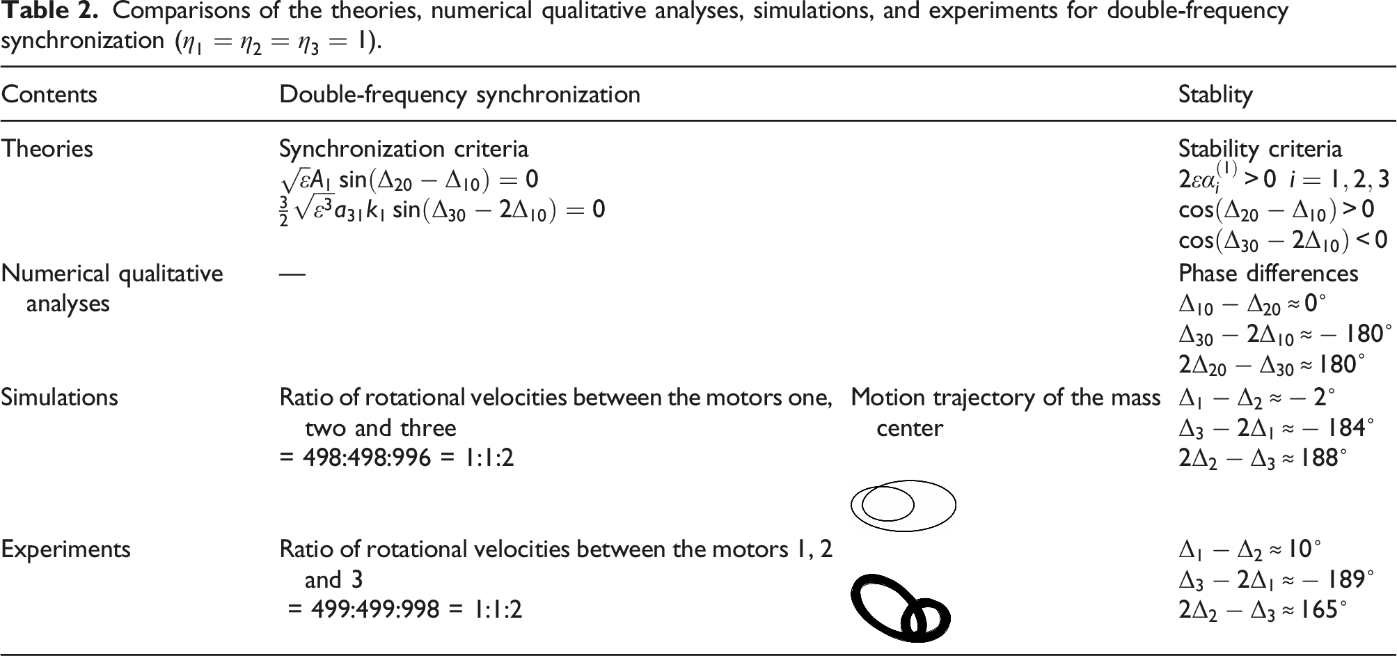
In this section, some corresponding comparisons on theories, numerical qualitative analyses, simulations, and experiments for double-frequency synchronization, are discussed, as shown in Table 2. Obviously, the experimental and simulation results are nearly identical with respect to the rotational velocities of the three exciters, and the steady state trajectory shapes at the center of mass are also very similar. According to the equations (13), (16), and (21), when the system achieves the synchronous and stable operation, the theoretically calculated value of the phase difference between the exciters one and two is 0, while that between the exciters one and three is , which is also reflected in the numerical analysis. However, there are some small deviations between the experimental and simulation results and the numerical analysis in the numerical comparison of the phase difference values. The reasons are as follows: (i) the included angles of the unbalanced blocks of each exciter are not exactly the same, resulting in different excitation forces, which affects the stable values of the phase differences among three exciters. (ii) even though the three motors used in the experiment are the same model, their actual electromagnetic output torques are not completely identical due to the voltage fluctuations and the effects of temperature and humidity on the parameters of the motors, so it is unlikely that the phase difference between the exciters will be exactly stable at 0 or . (iii) Other reasons for fluctuating phase differences include the damping of the system, misplacement of the sensor, etc.
Comparisons of the theories, numerical qualitative analyses, simulations, and experiments for double-frequency synchronization ().
Contents
Double-frequency synchronization
Stablity
Theories
Synchronization criteria
Stability criteria
Numerical qualitative analyses
—
Phase differences
Simulations
Ratio of rotational velocities between the motors one, two and three = 498:498:996 = 1:1:2
Motion trajectory of the mass center
Experiments
Ratio of rotational velocities between the motors 1, 2 and 3 = 499:499:998 = 1:1:2
Discussions on dynamic symmetry of the system
Generally speaking, for the synchronization system with the same driving frequency, we obtained the following conclusions: the better the dynamic symmetry is, the greater the synchronization capability will be, and the easier the system will be to achieve synchronization. We have also been trying to study the dynamic symmetry problem on times-frequency (double-frequency or triple-frequency) synchronization system driven by exciters, which needs to be discussed from the point of views of the coupling characteristics. Since there are no coupling terms among exciters in the average torque-balanced equations of motors for times-frequency synchronization system, we cannot study the times-frequency synchronization and dynamic symmetry from the coupling characteristics. Hence, in this paper, the asymptotic method is introduced to study the times-frequency synchronization problem.
In practical engineering, we can ensure the dynamic symmetry by enhancing the structural symmetry of system, that is, the exciters one and two (the same driving frequency) in Figure 1 are mounted symmetrically with respect to y-axis, this can ensure the dynamic symmetry of system as possible. However, in light of most vibrating machines used in engineering, the exciters one and two corresponding to Figure 1 are not completely symmetrically mounted on the rigid frame, especially the symmetrical layout of the exciter three is harder, because that it is limited by the actual machine structure itself and other factors (including the processing and assembly and subsequent maintenance and replacement convenience, etc.). Although the complete symmetry layout of three exciters in Figure 1 cannot be ensured, it does not also affect the realization of vibrating machines’ function for the times-frequency synchronous state.
Conclusions
The following conclusions are stressed
1. Based on the asymptotic method and averaging method, the basic equations for times-frequency synchronization of the system are obtained, which transforms the double and triple-frequency problem of three exciters into that of the existence and stability of zero-valued solutions of the mean differential equations. The synchronization criteria of the system under the fundamental-frequency and times-frequency conditions are derived, and the Routh–Hurwitz criterion is applied to obtain the stability criteria of the synchronous states.
2. The stability characteristics of the system are qualitatively analyzed numerically, and the stable phase differences of the system under the condition of different driving frequencies are not affected by the changing dimensionless parameter , that is, the distance between the rotation center of the exciter three and the centroid of the system has no influences on the system stability, but has an effect on the fundamental-frequency stability coefficients and , which tend to increase with the increasing .
3. According to the simulation and experimental results, the system can realize synchronous and ensure its stable operation by the double/triple-frequency state, and the stable phase differences in the steady state are approximately in accord with the results of the numerical analysis, this proves the validity of the used theoretical method. Moreover, changing the mass relationship among the exciters, has less effect on the simulation results, and the values of the stable phase differences do not change.
4. In practical engineering, the purpose of investigating the synchronization of exciters is to take advantage of the motion characteristics induced by the system synchronization, such as the linear motion, circular motion, elliptical oscillation, and so on. In this paper, we constructively propose a vibrating system with adjustable motion trajectory function, which can greatly improve the efficiency and performance of vibrating machines by applying two different driving frequencies to excite the system.
5. For present dynamic model, since the stable state of the system belongs to a single equilibrium state (i.e., only a set of stable phase differences, see Figure 4), the stable state of the system has nothing to do with the initial conditions and external disturbances. However, for some synchronous systems with multiple stable states, the final stable states of the system are related to initial conditions and external disturbances.
6. The present work can provide a theoretical guidance for designing some new types of vibrating machines with adjustable motion trajectories and different driving frequencies, especially for designing new vibrating separation machines.
Footnotes
Declaration of conflicting interests
The author(s) declared no potential conflicts of interest with respect to the research, authorship, and/or publication of this article.
Funding
The author(s) disclosed receipt of the following financial support for the research, authorship, and/or publication of this article: This work was supported in part by the National Natural Science Foundations of China [52075085] and the Fundamental Research Funds for the Central Universities [N2103019].
ORCID iD
Xueliang Zhang
Appendix
References
1.
WangYJingX. Nonlinear stiffness and dynamical response characteristics of an asymmetric X-shaped structure. Mech Syst Signal Process2019; 125: 142–169.
2.
SunXJingX. A nonlinear vibration isolator achieving high-static-low-dynamic stiffness and tunable anti-resonance frequency band. Mech Syst Signal Process2016; 80: 166–188.
3.
FengXJingX. Human body inspired vibration isolation: beneficial nonlinear stiffness, nonlinear damping & nonlinear inertia. Mech Syst Signal Process2019; 117: 786–812.
4.
BlekhmanII. Synchronization in science and technology. New York, NY: ASME Press, 1988.
5.
BlekhmanII. Vibration mechanics. Singapore: World Scientific, 2000.
6.
BlekhmanIIFradkovALTomchinaOP, et al.Self-synchronization and controlled synchronization: general definition and example design. Maths Comput Simulation2002; 58: 367–384.
7.
BlekhmanIISorokinVS. On the separation of fast and slow motions in mechanical systems with high-frequency modulation of the dissipation coefficient. J Sound Vibration2010; 329: 4936–4949.
8.
InoueJArakiYMiyauraS. Self-synchronization of mechanical system (multiple cycle). Proc Jan Mech Eng Soc1981; 42: 111–117, (in Japanese).
9.
WenBCFanJZhaoCY, et al.Vibratory synchronization and controlled synchronization in engineering. Beijing: Science Press, 2009.
10.
WenBCZhangHLiuSY, et al.Theory and techniques of vibrating machinery and their applications. Beijing: Science Press, 2010.
11.
BalthazarJMFelixJLPBrasilRMLRF. Short comments on self-synchronization of two non-ideal sources supported by a flexible portal frame structure. J Vibration Control2004; 10: 1739–1748.
12.
BalthazarJMFelixJLPBrasilRM. Some comments on the numerical simulation of self-synchronization of four non-ideal exciters. Appl Maths Comput2005; 164: 615–625.
13.
ZhangXLiZLiM, et al.Stability and sommerfeld effect of a vibrating system with two vibrators driven separately by induction motors. IEEE/ASME Trans Mechatronics2021; 26(2): 807–817.
14.
ZhangXYueHLiZ, et al.Stability and coupling dynamic characteristics of a vibrating system with one internal degree of freedom and two vibrators. Mech Syst Signal Process2020; 143: 106812.
15.
ZhangXGuDYueH, et al.Synchronization and stability of a far-resonant vibrating system with three rollers driven by two vibrators. Appl Math Model2021; 91: 261–279.
16.
FangPHouYJDaiLM, et al.Theoretical study of synchronous behavior in a dual-pendulum-rotor system. Shock Vib2018; 2018: 13, Article ID 9824631.
17.
ZouMFangPHouY, et al.Synchronization analysis of two eccentric rotors with double-frequency excitation considering sliding mode control. Commun Nonlinear Sci Numer Simulation2021; 92: 105458.
18.
KongXZhangXChenX, et al.Phase and speed synchronization control of four eccentric rotors driven by induction motors in a linear vibratory feeder with unknown time-varying load torques using adaptive sliding mode control algorithm. J Sound Vibration2016; 370: 23–42.
19.
KongXWenB. Composite synchronization of a four eccentric rotors driven vibration system with a mass-spring rigid base. J Sound Vibration2018; 427: 63–81.
20.
ChenXZKongXXZhangXL, et al.On the synchronization of two eccentric rotors with common rotational axis: theory and experiment. Shock Vib2016; 14: Article ID 6973597.
21.
HeJHEl-DibYO. The enhanced homotopy perturbation method for axial vibration of strings. Facta Universitatis: Mech Eng2021; 19, Number:. DOI: 10.22190/FUME210125033H.
22.
HeJHAmerTSElnaggarS, et al.Periodic property and instability of a rotating pendulum system. Axioms2021; 10: 191, DOI: 10.3390/axioms10030191.
23.
HeJHEl-DibYOMadyAA. Homotopy perturbation method for the fractal toda oscillator. Fractal and Fractional2021; 5: 93, DOI: 10.3390/fractalfract5030093.
24.
HeJHLatifizadehH. A general numerical algorithm for nonlinear differential equations by the variational iteration method. Int J Numer Methods Heat Fluid Flow2020; 30: 4797–4810.
25.
BogoliubovNNMitropolskyYA. Asymptotic methods in the theory of non-linear oscillations. India: Hindustan Publiching Corpn, 1961. (Translated from Russian).