
Abstract
This paper presents a new drilling tool with multidirectional and controllable vibrations for enhancing the drilling rate of penetration and reducing the wellbore friction in complex well structure. Based on the structure design, the working mechanism is analyzed in downhole conditions. Then, combined with the impact theory and the drilling process, the theoretical models including the various impact forces are established. Also, to study the downhole performance, the bottom hole assembly dynamics characteristics in new condition are discussed. Moreover, to study the influence of key parameters on the impact force, the parabolic effect of the tool and the rebound of the drill string were considered, and the kinematics and mechanical properties of the new tool under working conditions were calculated. For the importance of the roller as a vibration generator, the displacement trajectory of the roller under different rotating speed and weight on bit was compared and analyzed. The reliable and accuracy of the theoretical model were verified by comparing the calculation results and experimental test results. The results show that the new design can produce a continuous and stable periodic impact. By adjusting the design parameter matching to the working condition, the bottom hole assembly with the new tool can improve the rate of penetration and reduce the wellbore friction or drilling stick-slip with benign vibration. The analysis model can also be used for a similar method or design just by changing the relative parameters. The research and results can provide references for enhancing drilling efficiency and safe production.
Introduction
The demands for oil and natural gas are continually increasing, which have made the exploration and exploitation of oil and gas resources facing more complex downhole conditions. The traditional method for drilling is rotary drilling, which mainly uses turntables or downhole motor rotary drill bit to cut rock. However, when drilling encounters hard, broken rock formations, medium-hardness coarse-grained, inhomogeneous rock formations and the problems such as the low efficiency of breaking rock, the rate of penetration (ROP) will decline.1–4 Simultaneously, impact rotary drilling technology is an effective way to solve the problems mentioned above. Normally, an impactor is added to the upper part of a normal rotary drilling tool to transmit continuous and high-frequency impact loads to the drill bit, so the drill bit breaks the rock in both ways of impact and rotary cutting. This drilling rock breaking method is also called spiral drilling technology.5–9 Tian et al. designed several hydraulic impactors for oil drilling and conducted related theoretical research. 10 H. Gemov successfully designed a spool-type positive acting hydraulic impactor. 11 Emory successfully designed a valve-type reaction impactor. Gulf and Shell have designed hydraulic impactors, which can be used in oil and gas drilling and in solving stuck drill accidents. 12 Qin Xiaoqing et al. have obtained through experiments that the average mechanical drilling rate of rotary drilling is 26% higher than that of the same layer PDC bit, which is an important means for speeding up hard formation drilling. 13 Zhao Yunfei pointed out that the rotary drilling technology can effectively drill the hard stratum. 14
In the drilling field, the hydraulic oscillator and air hammers are used most widely. Among them, the hydraulic oscillator is widely used. However, ever since it was put into operation, the hydraulic oscillator has had a series of problems such as the complicated structure of the impactor, more parts being worn, and shorter stroke of the hammer due to the field use effect and the increasingly complicated drilling conditions.15–19 Impact and vibration frequency are sensitive to external factors and will change with the displacement and pressure of drilling fluid and other factors. It is hard to be consistent with the actual situation both in the research on the rock breaking mechanism of the tool and the personalized design of the bit. Therefore, it is difficult to ensure the best drilling tools, resulting broken bits which is less than ideal.20–25
With the change of exploration conditions of oil and gas reservoir and new demand for high efficiency or environmental protection, the downhole operation faces more complex and difficult condition; therefore, many demands have become more urgent such as improving ROP, reducing the friction between wellbore and drill string, avoiding the stick-slip phenomena, and so on.26–32 At the same time, exploration and exploitation of oil and gas inevitably lead to a more complex stratigraphy.
Therefore, for the reasons mentioned above, the new rotary-percussive positive displacement motor (PDM) was proposed, which utilizes the cam mechanism to produce a stable periodic impact force. This paper studies the impact theory of rotary drilling technology based on the cam mechanism. This paper applies the cam mechanism to oil drilling engineering for the first time and conducts theoretical derivation. The working principle of the new rotary-percussive PDM is introduced firstly. Then, the structural design and mechanical analysis of the cam impact system are carried out. Finally, the dynamic characteristics of the cam impact system are theoretically studied and compared with the experimental results. The research results can be applied to the rotary drilling technology, provide references for the research on technologies and tools related to anti-friction and drag reduction of drilling wells under the new conditions, and provide theoretical support for the field application of related tools.
Structural design and working mechanism
The new rotary-percussive PDM tool mainly consists of two parts, the powertrain and drive shaft-impact assembly. The conventional screw drill part structure is used as the powertrain. The mud enters the motor through the bypass valve, drives the motor rotor to rotate, and transmits the torque and the rotational speed to the drive shaft-impact assembly through the Cardan shaft, and finally enables the drill bit to break rock in a rotational impact manner through the impact device. The transmission shaft-impact assembly is attached to the lower end of the powertrain and is mainly composed of an upper shaft body, a bearing group, a cam mechanism, an impact pad, a lower shaft body, etc.
The new rotary-percussive PDM tool has an impact effect on the drilling process. The realization principle of the tool is based on the existing screw drilling tool and the cam structure of the impact function in the transmission shaft section. When the tool is operating normally, the high-pressure mud passes through the inside of the bypass valve housing to enter the interior of the screw drill and then transforms its hydraulic energy into the mechanical energy of the motor rotor. The rotation of the rotor, in turn, drives the universal shaft and the upper shaft body to rotate. Since the upper shaft body and the lower shaft body are splined together, the cam, the base, and the lower shaft body are sequentially connected through a thread, so the lower shaft body and the cam also rotate along with the upper shaft body. Due to the structural features of the cooperation of the cam and the roller, the cam drives the roller to rotate during the rotation to push the upper part of the drill to raise up and then drop down at the high point. After the collision, the screw motor continues to drive the cam to rotate, the upper drill assembly intermittently collides with the impact pad and results in an impact. In this way, the function of the rotary impact crushing rock is realized.
Theoretical model
The drive shaft-impact assembly of the new rotary-percussive PDM mainly includes the impact system, the bearing system, and the oil seal system. The core of the impact system is the reciprocating movement of the upper tool by the cam mechanism. The upper shaft body, the impact nozzle, etc. as the hammer first impacts with the impact pad. The lower shafts and others impact subsequently, and then the roller makes contact with the cam. This paper mainly studies the design and analyses the mechanics of the impact system.
In general, the power of the cam rotation comes from the upper screw motor. As is shown in Figure 1, when the tool is operating normally, the high-pressure mud enters the interior of the screw drilling tool through the inside of the bypass valve housing and converts its hydraulic energy into the mechanical energy of the motor rotor when passing through the motor assembly. The rotation of the rotor, in turn, sequentially drives the universal shaft and the upper shaft body to rotate. Since the upper shaft and the lower shaft body are connected by splines and the cam and the lower shaft are screwed, the lower shaft can drive the cam to rotate. That means the cam will rotate with the upper shaft under the action of the upper screw motor.
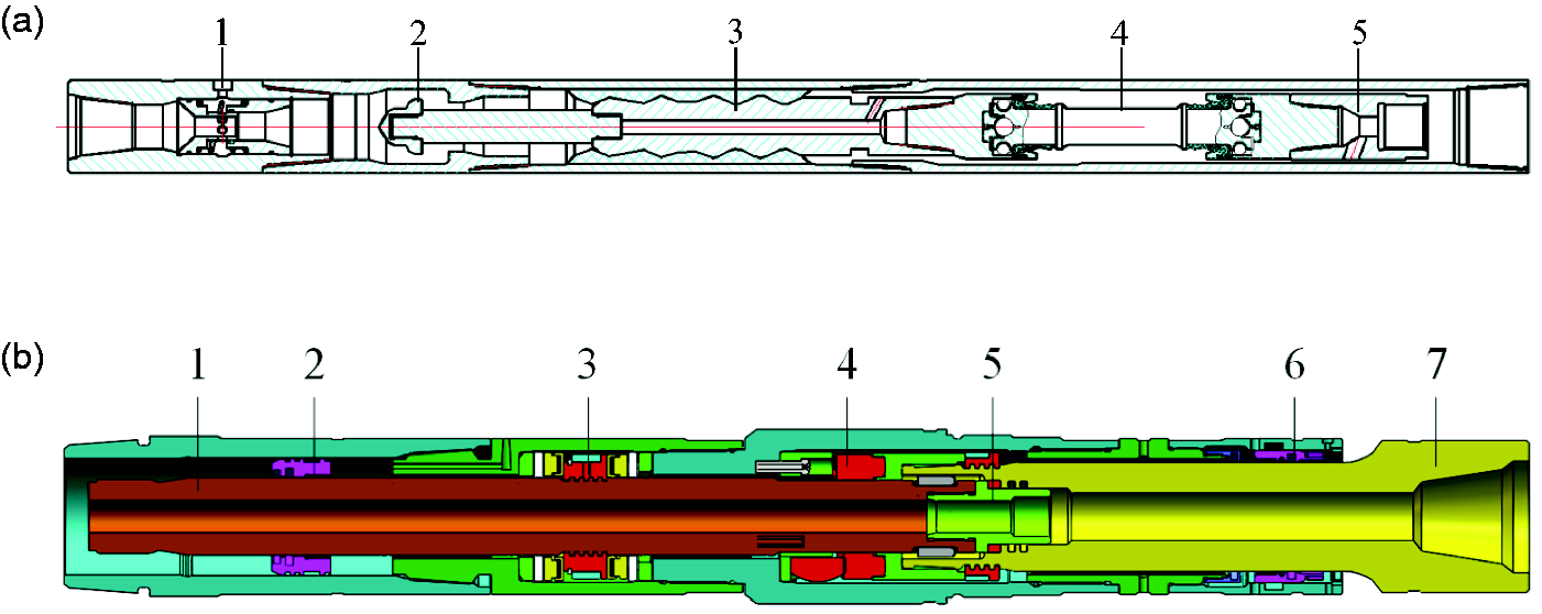
The new rotary-percussive PDM tool. (a) The powertrain structure diagram (1: bypass valve; 2: anti-drop device; 3: motor; 4: Cardan shaft; 5: water valve bonnet) and (b) drive shaft–impact assembly structure diagram (1: upper shaft body; 2: upper balance piston; 3: bearing group; 4: cam mechanism; 5: impact pad; 6: lower balanced piston; 7: lower shaft body).
The cam curve is designed according to the working principle of the tool. When the roller climbs to the top of the cam, it descends with a certain acceleration, so there is a need to consider the influence of gravity. In the meantime, the cam curve is also designed in a way to prevent the roller from generating a large impact force at the bottom of the cam so that the cam mechanism is not damaged due to fatigue. When designing, the upper shaft body should be ensured to directly strike the impact pad before the cam mechanism. Cam mechanism movement process is shown in Figure 2.
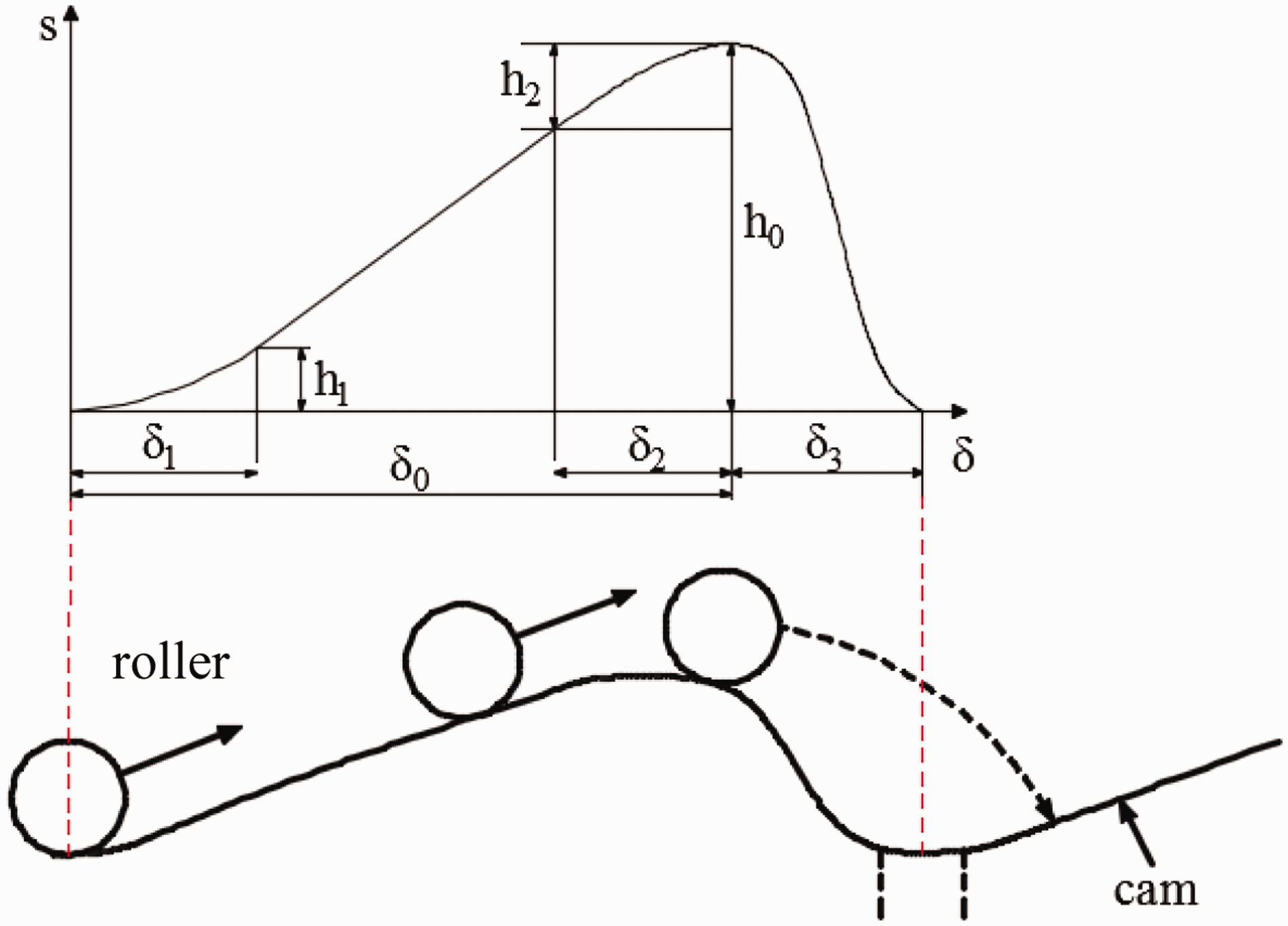
Roller-cam movement process.
The face cam includes three identical raised portions, and the motion profile of each raised portion includes a pitch phase and a return phase. i1 = 0°∼ δ0 is the phase of the end face of the cam and i2 = δ0 ∼120° is the return of the end face of the cam. According to the working condition of the new rotary-percussive PDM, the cam movement curve can be designed by the motion law of the cycloidal-linear-cycloidal, as shown in Figure 2.
The process consists of three stages of motion curve, the movement curve equation
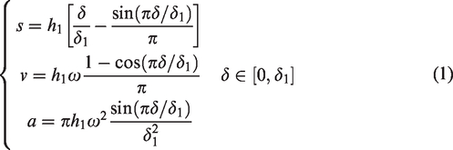
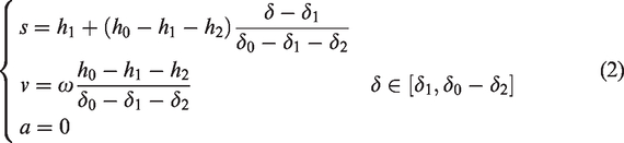
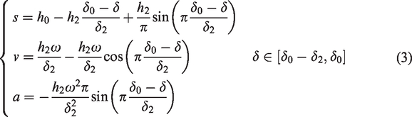
Returned phase sine acceleration section, the movement curve equation is
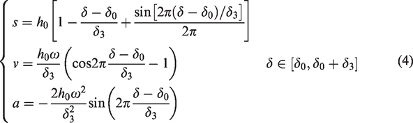
According to the principle of combination of sports, it is necessary to ensure that the motion parameters of the two stages of motion are continuous at the convergence point. Let δ = δ1, equations (1) and (2) equal velocity (v) in two equations, and we can get
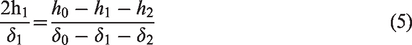
And let
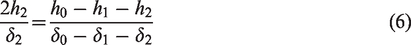
In addition, when δ = δ0, equations (3) and (4) are equal in velocity and equal to 0 in both equations.
In general,
As shown in Figure 3:
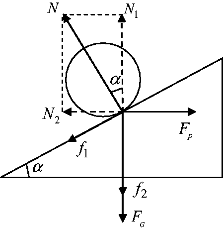
Schematic diagram of force analysis of impact structure.
The following formula is derived based on the stress analysis in Figure 3

In the formula,
According to Figure 3, the force analysis shows that the output torque of the screwdriver is balanced with the torque generated by the


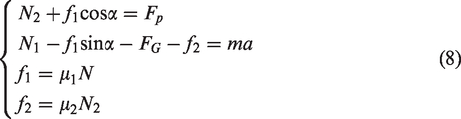
As shown in Figure 4, the theoretical model of the impact of the tool assumes that the local deformation of the impact surface of the upper shaft and lower shaft is proportional to the force of the impact. Therefore, there is the massless spring between the lower and upper ends of the upper and lower shaft. The deformation coefficient is kcc. The mass of the upper shaft is Mcc, the speed before impact is Vcc, and the force exerted on the impact surface is F. The lower shaft from the impact surface of the Shun wave force is F2. The force of the reverse wave pointing to the impact surface is F3, the speed of the two kinds of wave particles is respectively v2 and v3. The velocity of the upper shaft after striking is V1, and the velocity of the upper surface of the lower shaft after striking is V2. The above parameters except kcc and Mcc are functions of time.
Cam combination impact theory model.
Derived from Newton's law
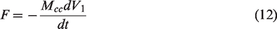
Derived Hooke's law
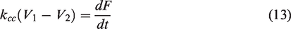
Obtained by the superposition of waves


Derived from the basic relationship between the waves


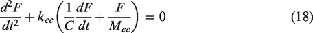
Substituting equations (12), (14), (15), (16), and (17) into equation (13), the second-order differential equation of the shaft under the impact of the upper shaft body is obtained, and that is (see Appendix 1)
The initial condition is
Among them
The mean of the impact
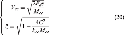
Let

Determine the derivative of the above formula to find the peak impact formula
Numerical examples and simulation analysis
Numerical examples
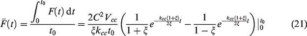
According to the actual working condition of drilling, the example analysis is made according to the cam kinematics and mechanics model established in the previous section. The analysis of the relevant parameters is given in Table 1.
Cam structure design parameter table.
To describe the actual force between cam and roller more accurately, the parabola effect is considered to determine the contact point between roller and cam. As shown in Figure 5(a) for the roller in the cam speed is 90 r/min, 120 r/min, 150 r/min in case of motion trajectory, the effective roller stroke is 11.87 mm, 11.37 mm, 10.64 mm. There is a certain impact about this impact force on the actual tool, cam contact force etc.
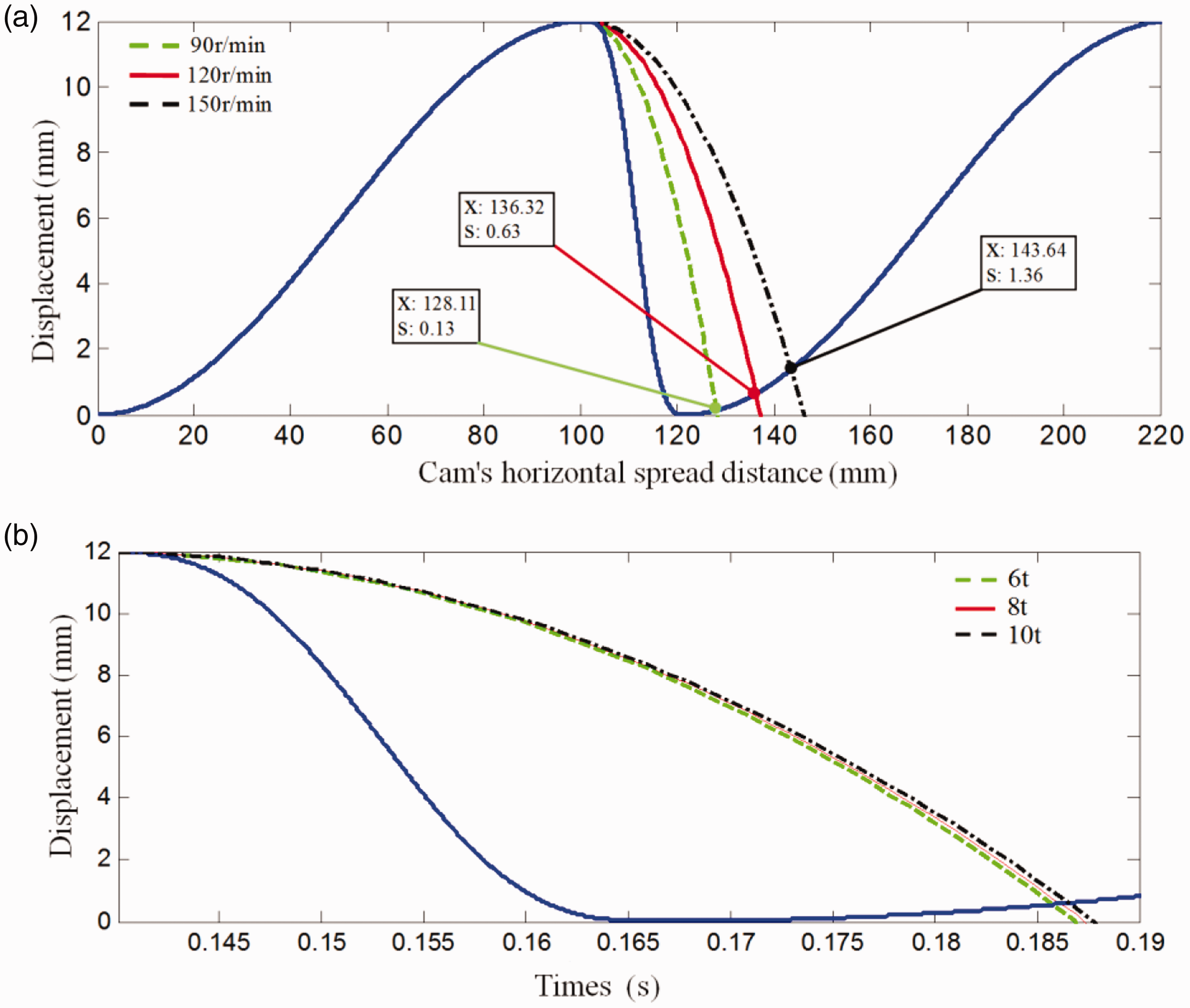
The trajectory of the roller in the parabolic effect and drill string rebound. (a) The trajectory of the roller in the parabolic effect; (b) The trajectory of the roller in the drill string rebound.
Considering the gravitational acceleration, the backing force of upper drill assembly as an elastomer, that is, drill string rebound also has an impact. Combined with the actual drilling tool screw combination, the equivalent basic parameters of the drill pipe are shown in Table 1; according to the basic parameter table, the calculated the equivalent acceleration of the drill pipe are 10 m/s2, 10.2 m/s2 and 10.4 m/s2. The movement of the roller down the track is shown in Figure 5(b). The effective stroke of the cam is 11.45 mm, 11.42 mm, and 11.40 mm at the rotational speed of 120 r/min and under the three different drilling pressures of 6t, 8t, and 10t respectively.
When the rotate speed of cam is 120 r/min, the position of the contact point between the cam and the roller is determined, and the mechanical analysis result is shown in Figure 6. It can be seen from Figure 6 that as the WOB increases, the force generated between the cam and the roller also increases. In the pushing stage, the force between them gradually decreases with time. When the highest point of the cam reaches the minimum value (6t of the WOB), the range of the force produced by the cam mechanism is from 7.49t to 4.39t, from 10.26t to 5.59t at 8t WOB, and from 12.91t to 6.95t at 10t WOB. In the return phase, the roller does not touch the cam return due to the parabolic effect. The force between the shaft suddenly decreases, and the upper shaft body and the roller member descend rapidly. Since the upper shaft stroke is smaller than the cam stroke, the upper shaft is struck before the impact pad. So, the impact force generated between the cam and the roller is greatly reduced, which increases the service life of the cam mechanism.
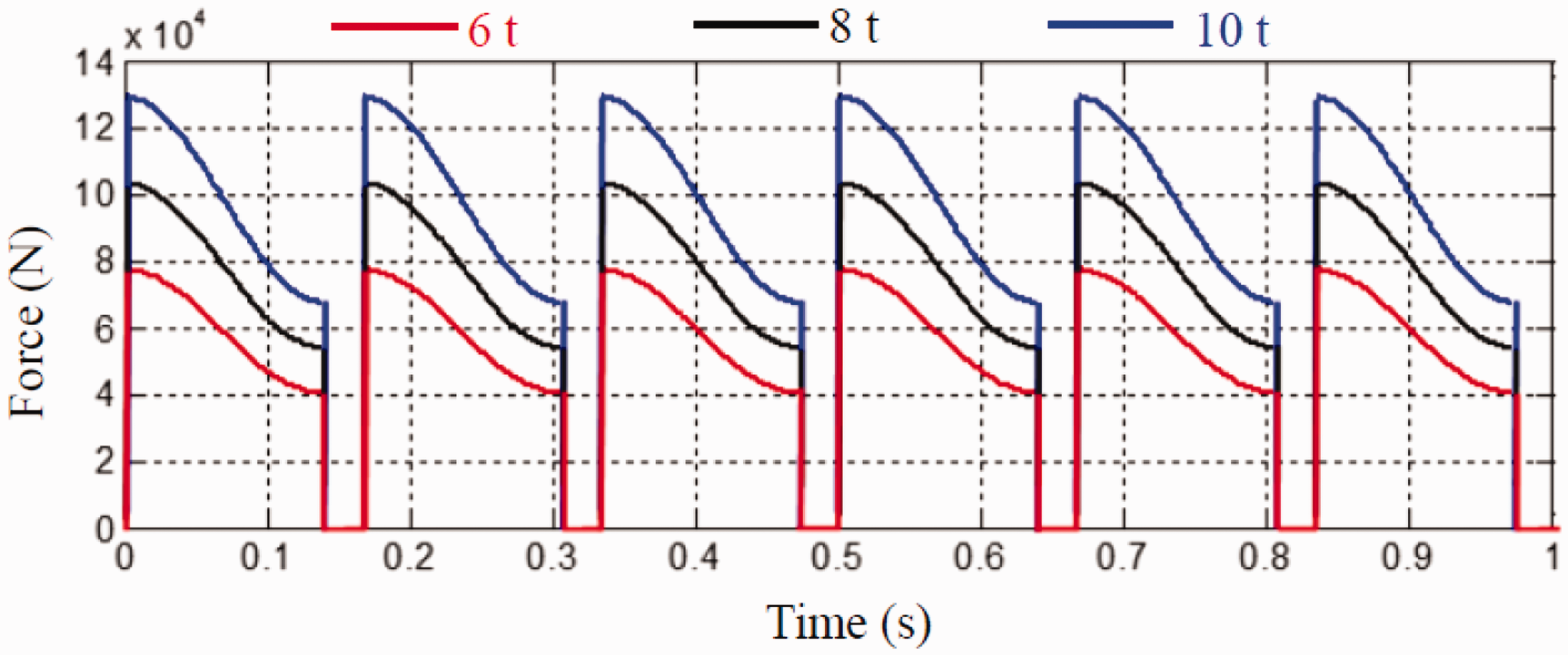
Cam–roller force analysis results at different WOB.
According to the established calculation method, the influence of WOB and impact deformation coefficient on impact force is analyzed. From Figure 7(a), it can be seen that the impact force changes from 6.84t to 15.29t when the WOB varies from 2t to 10t, showing approximate linear characteristics, and the change of WOB has a greater impact on the maximum impact force. From Figure 7(b), it can be seen that the impact force increases with the impact deformation coefficient of the upper shaft and varies from 9.9t to 11.86t, showing obvious nonlinear characteristics. The results show that the impact force increases with the increase of the WOB and shows obvious linear characteristics. The impact deformation coefficient and impact force showed a nonlinear characteristic, which is due to the impact deformation coefficient increases, and the impact time becomes shorter, resulting in an increased impact force. At the same time, from the design of the impact deformation coefficient and the influence factors of the stiffness in the actual working condition, when the spring stiffness changes greatly, the change value of impact force is slight. The results of the research can provide technical support for the next tooling downhole experiment and can control the ROP by changing the WOB, downhole speed, and dial rotation speed according to the working conditions of specific sections.
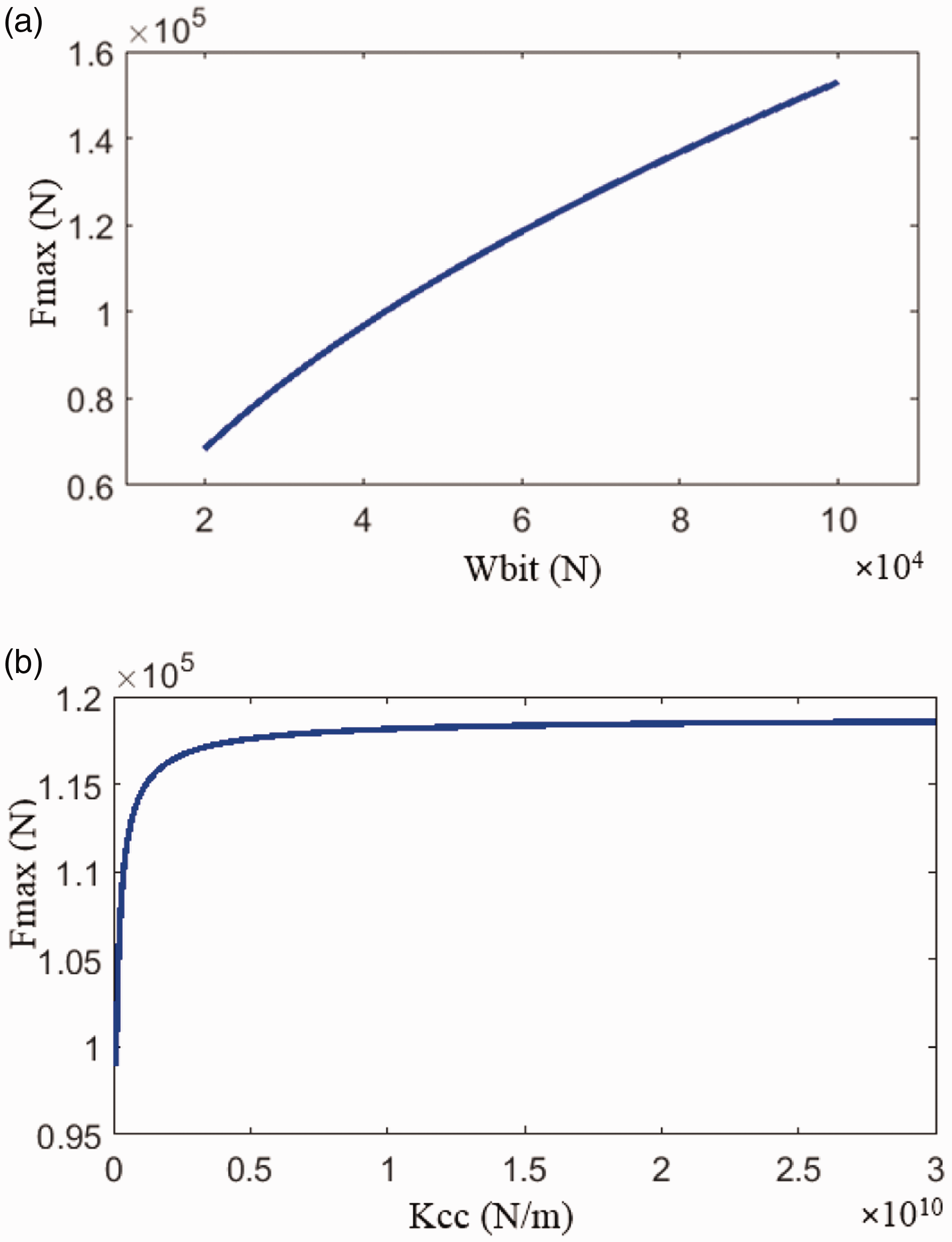
The effect factors of impact force. (a) The relationship between impact and weight on bit; (b) The relationship between impact force and impact deformation coefficient.
Simulation analysis
In this paper, the ADAMS software is used to analyse the impact dynamics of the new rotary-percussive PDM tool, by using the three basic simulation modules of View, Solver, and PostProcess in software. To carry out the simulation calculation and analysis of the tool, a simplified model of the impact and support system of the screw drilling tool is established, as shown in Figure 8. To shorten the running time of the computer, spare parts that have a significant influence on the simulation effect of the impact and bearing system are retained, and the secondary parts are ignored.
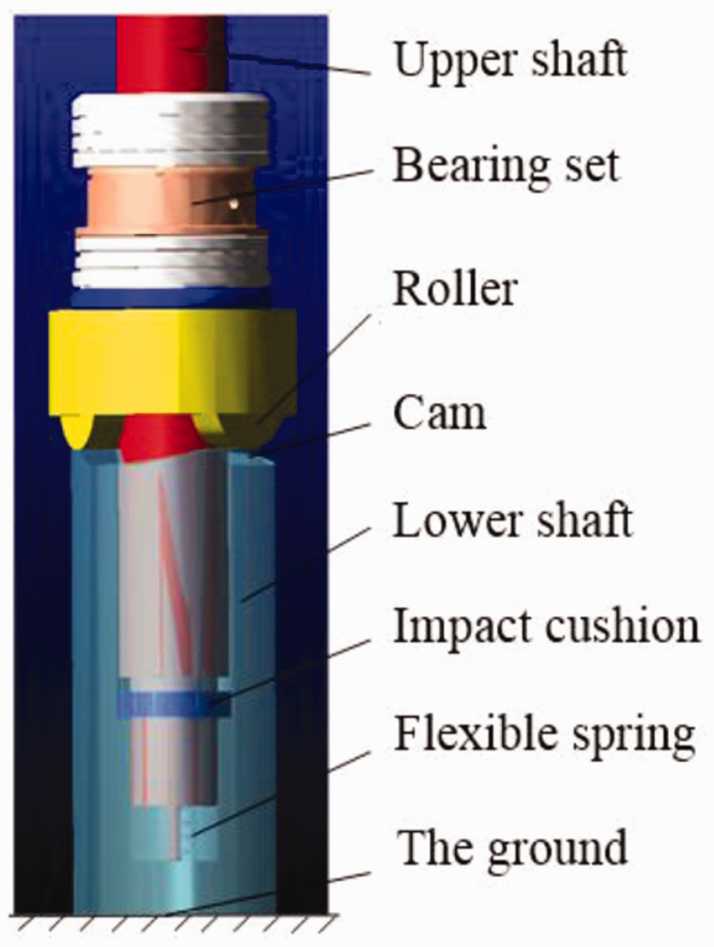
Impact and bearing system simulation model.
The load applied to each component includes external loads, flexible connections, and special loads. The external load includes space fixing force and gravity. The members are flexibly connected by springs, flexible beams, dampers, force fields, etc. The interaction force and moment are considered only in the flexible connection relationship, regardless of the quality of the joint portion. A flexible spring connection is applied between the upper shaft and the impact cushion. Also, there are special loads in the impact and bearing system. The contact force generated by the cam and the roller during the pushing phase and the intermittent contact force between the upper shaft and the impact cushion is considered in the model. The constraint is added so that the lower shaft can be rotated and slipped along the axis, and the upper shaft can slide along the axis. The relative position between the roller and the upper shaft is fixed so that the impact between the upper shaft and the impact pad occurs before the roller and the cam when the roller climbs to the highest point.
The contact force between the roller and the cam is measured by simulation, as shown in Figure 9(a) to (c). By comparing and analyzing the theoretical calculation results in Figure 9, we can see the following results.
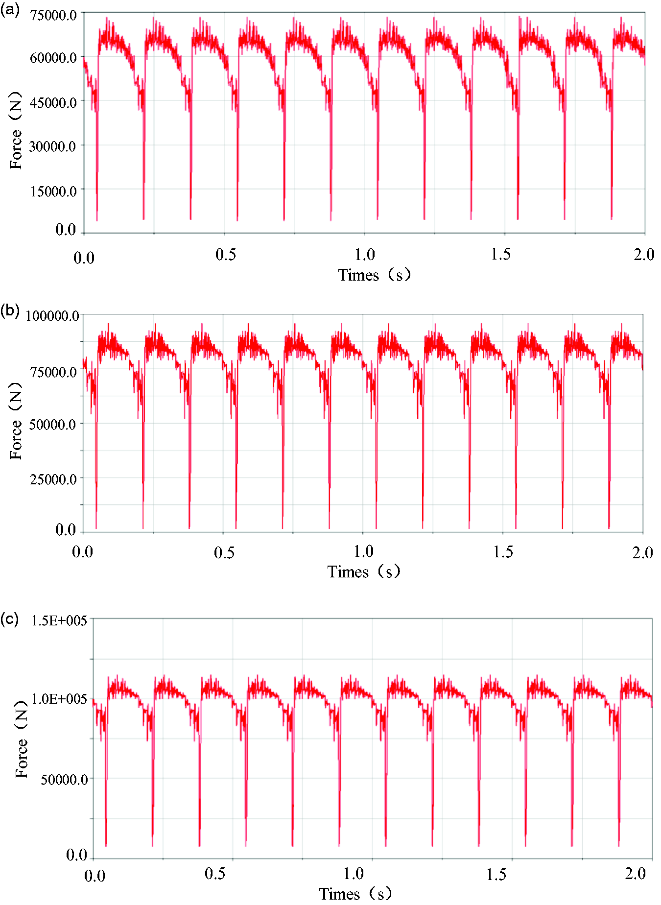
The simulation results of contact force between cam and roller. (a) The contact force between cam and roller when WOB = 6t; (b) The contact force between cam and roller when WOB = 8t; (c) The contact force between cam and roller when WOB = 10t.
It can be seen from the simulation results that as the WOB increases (6t–10t), the force generated between the cam and the roller also increases, and the fluctuation range also increases, and the load on the cam mechanism becomes large. During the push phase, the force between the two gradually decreases over time and reaches a minimum at the highest point of the cam. When the WOB is 6t, the range of the force generated by the cam mechanism is from 7.13t to 4.17t, and the error between the simulation result and the theoretical calculation result ranges from 2.14% to 5.01%. When the WOB is 8t, the cam mechanism produces the same function. The force variation range is 9.25t–5.82t, and the error between the simulation result and the theoretical calculation result is 9.84%–4.11%. When the WOB is 10t, the range of the force generated by the cam mechanism is from 11.57t to 7.35t. The error between the result and the theoretical calculation results ranged from 10.38% to 5.76%. Within a certain range, the theoretical calculation of the force between the cam and the roller is basically consistent with the trend and fluctuation range of the simulation results.
The friction between the drill string and borehole wall is one of the main causes of the stick-slip of drill string. The new rotary-percussive PDM tool can generate axial vibration, that is, the fluctuation of WOB, which can change the contact state between the drill string and borehole wall and converts the static friction to dynamic friction. Consequently, friction and stick-slip are reduced. At the same time, the axial vibration is transformed into the dynamic impact load of the auxiliary drill bit breaking rock, which reduces the dragging of the drilling tool during the sliding drilling, enhances the WOB transmission capacity, accelerates the rock breaking and improves the drilling efficiency. Therefore, the tool can apply an impact force to the drill bit while rotary drilling, and utilize the characteristics that the rock is easily broken under the impact force to improve the ROP.
Experimental tests
The well structure is shown in Figure 10. To verify the accuracy and rationality of the theoretical analysis models, we carried out the corresponding field test. Trial section 4360 m–5371 m, combination of drilling tools: ϕ241.3 mm PDC bit + ϕ177.8 mm rotary-percussive PDM + adapter + ϕ203.2 mm measuring short section + ϕ203.2 mm non-magnetic drill collar + ϕ239 mm centralizer + ϕ196.85 mm drill collar + ϕ239 mm centralizer + ϕ196.85 mm drill collar + adapter + ϕ177.8 mm drill Collar + ϕ127 mm heavier drill pipe + ϕ127 mm drill pipe. According to the actual conditions and the problems that occurred at the site, four sets of screwing drills are selected for drilling. The WOB is mainly 6t–10t, and the rotating speed is 60 r/min, displacement is mainly 30 L/s–34 L/s, pump pressure is 25 MPa–26 MPa and the specific parameters are shown in Table 2.
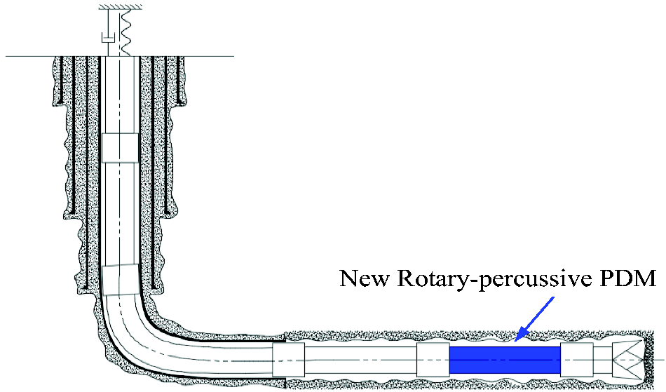
Well structure.
Drilling parameters.
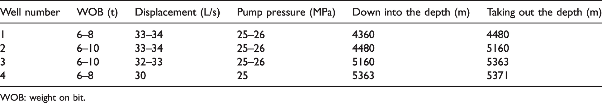
WOB: weight on bit.
After the downhole experiment, the rotary drilling tool was taken to the factory for analysis where we found less wear on the cam roller mechanism and that the cam could work normally. As shown in Figure 11, the cam seat is intact, and the cam curve is not damaged. It is only slightly corroded and can still be used normally. The cam climbing surface has a slight trail of rollers. Since because the roller and the upper shaft are lifted during the climbing stage, the contact surface between the roller and the cam is subjected to the drilling pressure, so the cam is pressed out of the slight groove, which is normal and conforms to the design result.
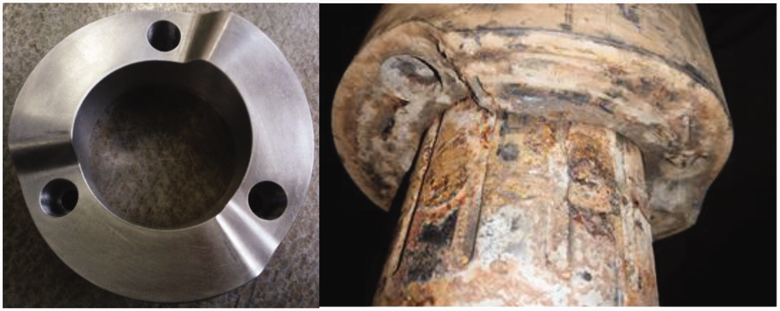
Cam mechanism after the downhole experiment.
The comparison of the bearings before and after the downhole experiment is shown in Figure 12. The bearing roller shape after the experiment is intact, and it is not deformed due to the excessive impact force, indicating that the bearing can withstand the flexible impact generated by the cam.
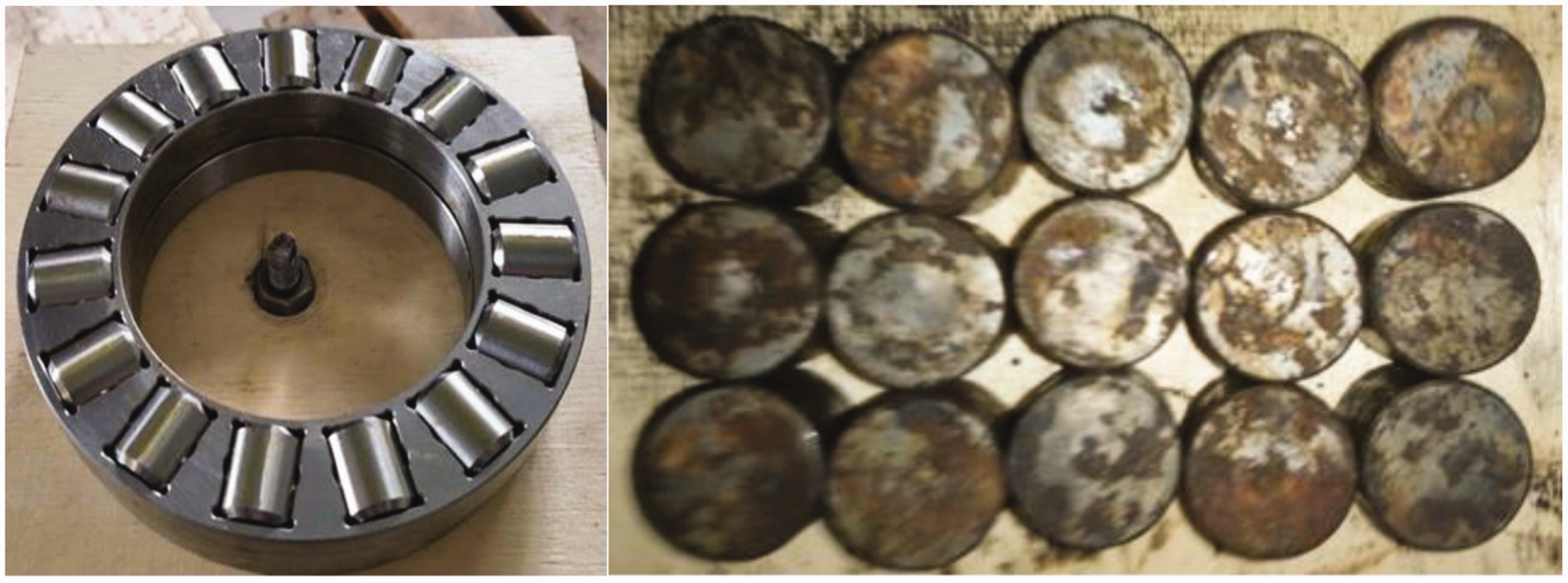
The bearing before and after the experiment.
The three wells A, B, and C are adjacent wells, with similar geographical locations and same rock composition. Since the mud density is similar, the three wells A, B, and C are compared. As shown in Figure 13, the C well used New Rotary-percussive PDM with an average ROP of 6.88 m/h, an increase of 134% over the average ROP of the A-well and an average ROP of more than that of the B-well increased by 155%. From this, we can conclude that the C well using spiral screw drilling tools has the obvious speed-raising effect, greatly shortens the drilling period, and saves the drilling cost. This paper shows the necessity and accuracy of the research on the impact system of the new rotary-percussive PDM.
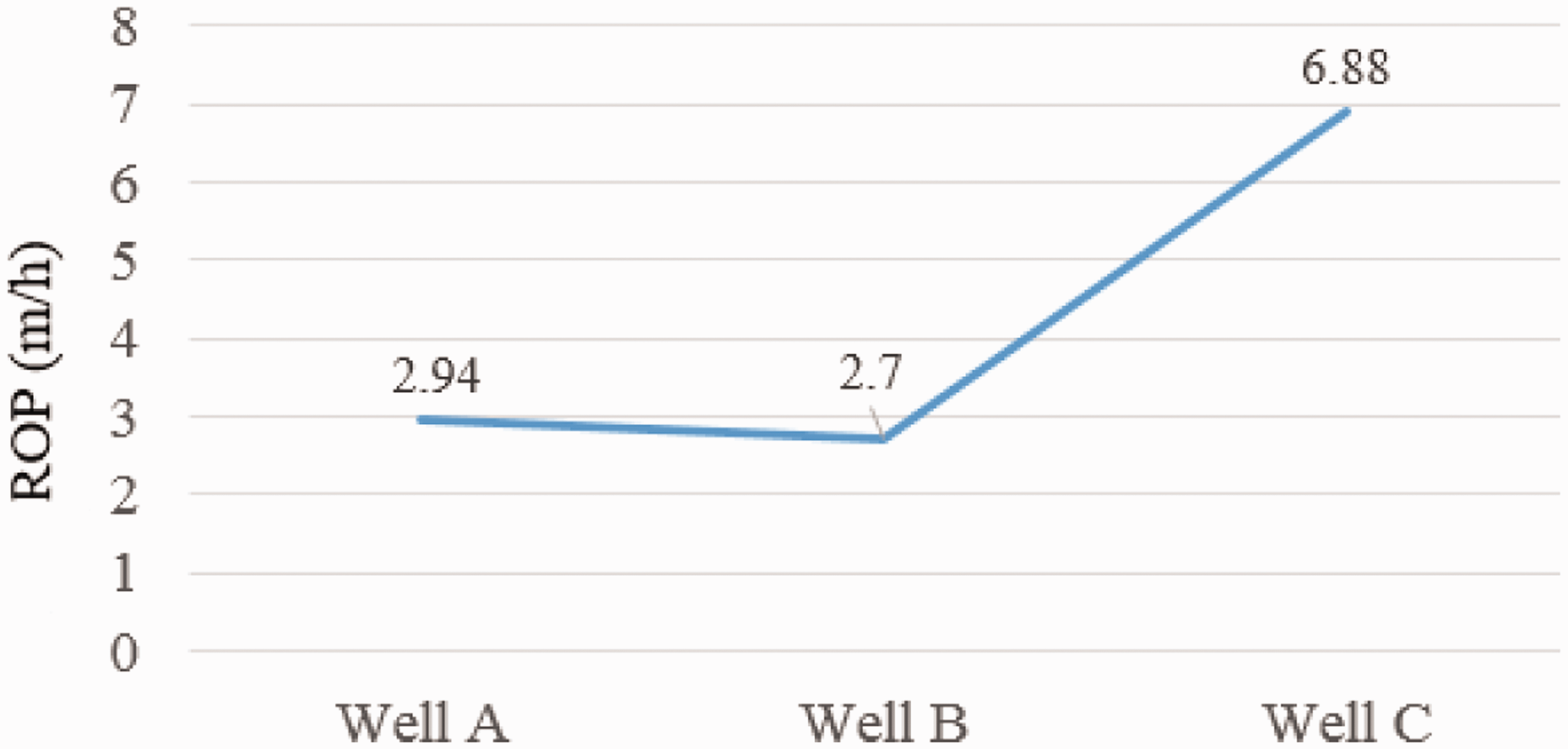
Test well and adjacent wells ROP contrast.
To verify the reliability of the study, the simulation results were compared with the test results, as shown in Figure 14. As can be seen from the figure, the simulation results have slightly larger values than the test results. The possible reasons include the WOB instability during the test, the test method, and the accuracy of the test instrument. Since there is small expected error in the test results, the reliability of the simulation calculation and the rationality of the design are verified within a certain range. Therefore, the results have significance reference for rock breaking process by rotary drilling.
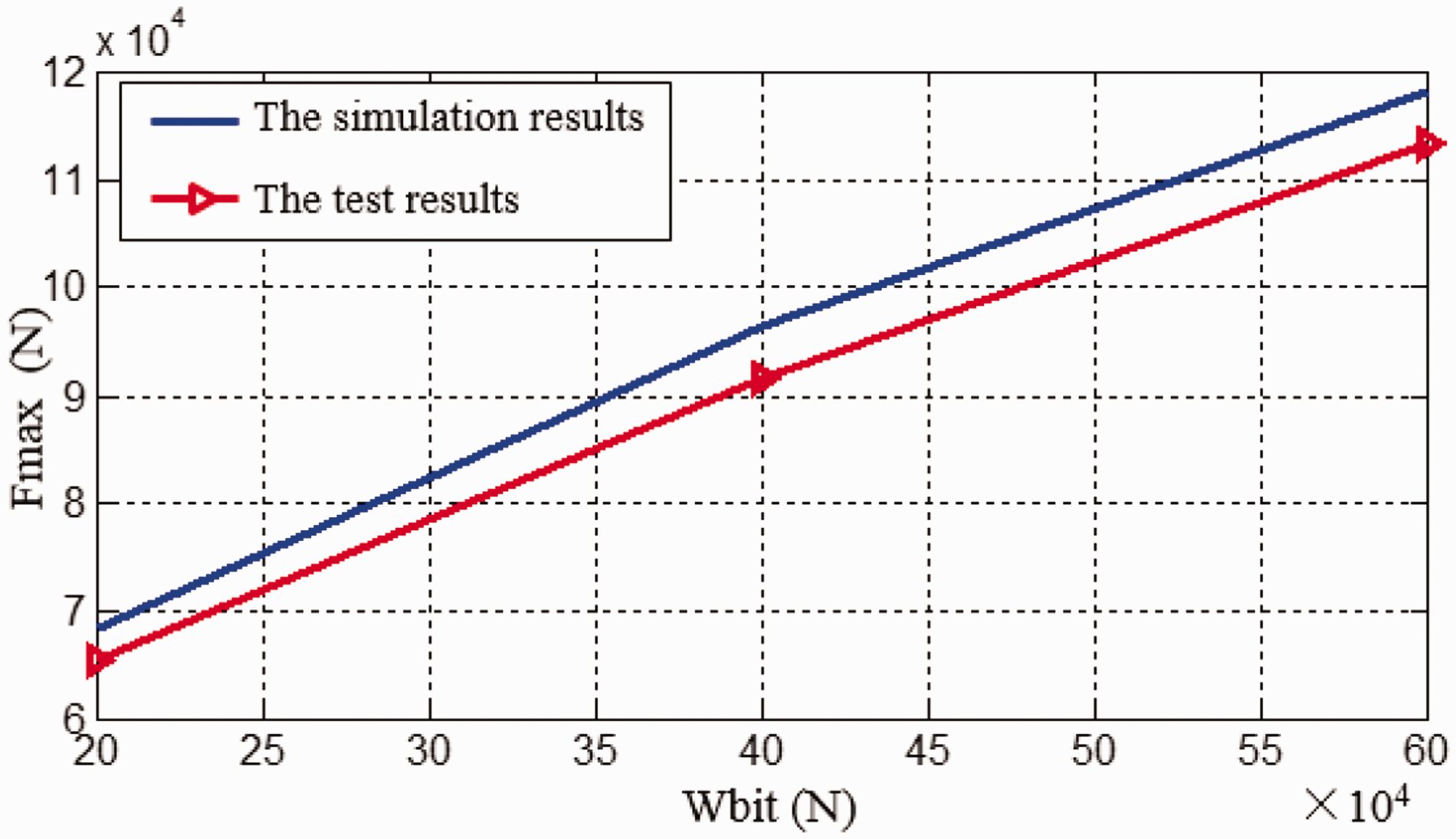
The comparison of the simulation results and test results of the maximum impact force.
Conclusions
This paper studied the working mechanism and dynamics characteristics of a new rotary-percussive PDM with a cam structure. The torque generated by the screw drive the mandrel to achieve the relative movement of the roller in the cam curve, which can achieve impact in the return phase. A new type of screw-drilling collision model was established, and this paper analysed the relationship between the peak impact force and WOB. According to the example of analysis and experiment, the accuracy and reliability of the calculation method were verified. The results show that the impact force increases with the increase of the WOB and shows obvious linear characteristics. Moreover, the impact deformation coefficient and the impact force also exhibit nonlinear characteristics.
Through the use of the new screwing-drilling tools and shock absorbers, the new design in this paper can produce a continuous axial impact. This impact is a smooth high-frequency vibration, which can change the axial static friction between the drill string and the shaft wall to sliding friction. Moreover, the rock breaking form of the drill bit is converted from rotary shear to rotary chisel cutting to improve drilling efficiency.
The experimental results show that the new rotary-percussive PDM will produce continuous and stable periodic axial impact force, which is useful for solving the problems of the previous hydraulic oscillator of being not effective and the bit having a low rock breaking efficiency. And the results can be applied to the spin-drilling, support reference for the research on the related technologies of anti-friction and anti-drilling for drilling and rock breaking in the new conditions, and provide theoretical support for the related application.
Footnotes
Declaration of conflicting interests
The author(s) declared no potential conflicts of interest with respect to the research, authorship, and/or publication of this article.
Funding
The author(s) disclosed receipt of the following financial support for the research, authorship, and/or publication of this article: All authors gratefully acknowledge the support of the Open Fund of Key Laboratory of Oil & Gas Equipment (OGE201701-02), Ministry of Education (Southwest Petroleum University), The State Scholarship Fund of the China Scholarship Council (CSC) (No. 201608515039), National Natural Science Foundation of China (NSFC) (No.51674216), National Science and Technology Major Project (No.2016ZX05038).
Appendix 1
The derivation of
Derived from Newton's law
Derived Hooke's law
Obtained by the superposition of waves
Derived from the basic relationship between the waves
Bringing formula (27) to formula (25) gives
Bringing formula (28) and (29) to formula (30) gives
Bringing formula (26) to formula (31) gives
Bringing formula (24) to formula (32) gives
The above formula can be transformed into
Formula (24) can be transformed into
Bringing the above formula to formula (34) gives
Appendix 2
From the revised manuscript, the second-order differential equation of the shaft under the impact of the upper shaft body is obtained
Formula (37) can be transformed into
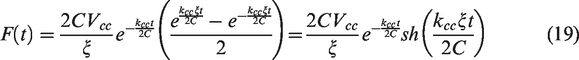
The solution of formula (38) is
From formula (40), it can be obtained
Bringing formula (41) to formula (39) gives
So, the solution of the differential equation (14) can be expressed as
Among them