
Abstract
The phase sensitivity of the condenser type acoustic transducers at low frequencies is crucial for locating large-scale natural and manmade activities, but is now commonly calibrated based on comparison methods. Although the primary method, which traces its sensitivity back to the international standard unit is few studied. Recently, the explicit sensitivity models of the condenser type acoustic transducers based on the laser-pistonphone technique are built, and can be used to study the phase responses of acoustic transducers at infrasonic frequencies. So that, in this paper, the phase sensitivities of acoustic transducers when its rear vent connected to the calibrating sound field or outside atmosphere are studied in detail. Secondly, time domain analysis of generated sound pressures by displacement excitation are derived to reveal the mechanism of phase variation. Calculations show two distinct sensitivities with 90° phase lead and −10° phase lag limits for vent in field and vent out field calibrations, which are dominated by the pressure leakage and heat conduction effects at infrasonic frequencies.
Introduction
Infrasounds are commonly produced by large-scale natural and manmade activities, earthquakes, volcanic eruptions, landslides, nuclear explosions, spacecraft launch and landing, etc., and have caused wide concern in recent years. The most valuable infrasound measurement is originated from the localization of the nuclear explosions.1–3 When the Comprehensive Nuclear Test Ban Treaty was proposed, the infrasound monitoring network was chosen as one of the four ways to locate the nuclear tests. These sound source localizations are based on measuring the time difference it takes for the sound waves to reach different acoustic transducers or specialized acoustic actuators in the network.4–8 So that their phase sensitivities are the most critical index affecting the measurement accuracy.
There are many methods that can be used to calibrate acoustic transducers at infrasonic frequencies.9–12 At present, the phase response of acoustic transducers are commonly calibrated using in-situ or calibrator methods to get their phase consistency,13–16 while the primary calibration (mainly includes the reciprocity technique and pistonphone),17–19 by which the acoustic transducer is calibrated with reference to non-acoustic standards and with the highest possible precision, is few studied. R. Jackett et al. have determined the phase sensitivity uncertainty of microphone based on the reciprocity technique, and found that the low frequency uncertainty due to leakage in microphone cannot be ignored.20,21 T. M. Marston developed a pistonphone, working in the frequency range 0.002–20 Hz. The microphone was completely immersed in the calibrating sound field, and the reported phase sensitivity show phase lead phenomena at low frequencies. 22 F. Larsonner et al. studied the phase sensitivities of microbarometers MB2005 and MB3 based on the pistonphone technique and also reported the phase lead phenomena. 23
The phase lead phenomena at low frequencies are clear, but it can only be roughly verified by measurements, while its variation mechanism and quantitative analysis are difficult to be implemented. The reason is that the current sensitivity model is defined as the quotient of the measured acoustic transducer voltage to the theoretical incident sound pressure as a function of frequency,
24
as shown in Figure 1. In such case, the response variation of the acoustic transducer is drowned in the measured voltage and cannot be explicitly characterized. Schematic diaphragm of the pistonphone calibration.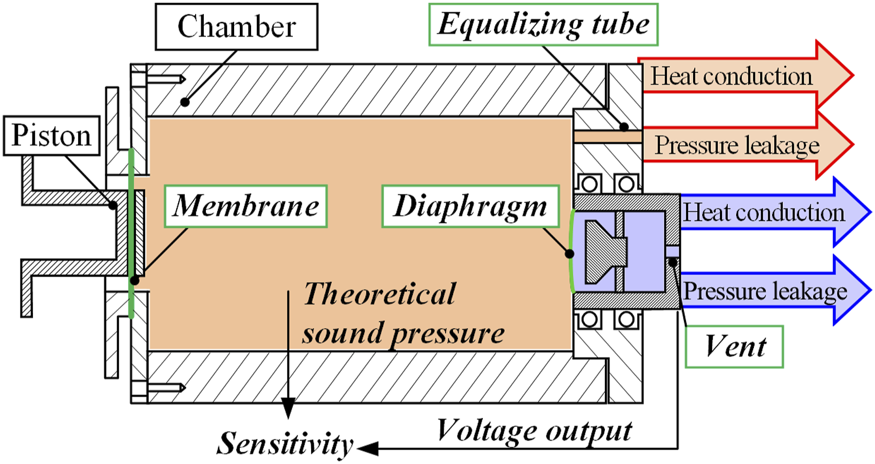
In-depth analysis has showed that the primary calibration of the acoustic transducer at low frequencies contains two coupling mechanisms. Firstly, sound pressures both in the pistonphone and acoustic transducer will decrease due to the coupled pressure leakage and heat conduction effect.25,26 Secondly, these sound pressures couple with the diaphragm elasticity, and determine the diaphragm deformation.27–29 Based on these, explicit sensitivity models characterizing the relationship between the diaphragm deformation and structures of acoustic transducer and pistonphone were derived. 27
The new models provide us with a means of studying the acoustic transducer phase response theoretically. So that in this paper, the phase sensitivities of acoustic transducer at infrasonic frequencies, particularly when its rear vent connected to the calibrating sound field or outside atmosphere are studied in detail. Secondly, time domain analysis of generated sound pressures by displacement excitation are derived to reveal the mechanism of phase variation. Calculations show distinct sensitivities for vent in field and vent out field calibrations dominated by the pressure leakage and heat conduction loss at infrasonic frequencies. It is therefore recommended to obtain the primary phase sensitivity before serving.
Phase sensitivity of acoustic transducers
Sensitivity models (in brief)
The modeling process of the recently derived sensitivity models is brief listed as below for further study.
27
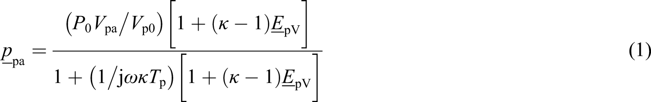
The physical prototype of modeling is based on a currently designed laser-pistonphone as shown in Figure 2. The chamber is made of seamless steel, thus ensures stable heat conduction effect. A tiny equalizing tube is opened at the end cover to provide the static pressure equilibrium. The lower frequency limit of the laser-pistonphone is 0.01 Hz. The calibrating sound pressure is produced by the sinusoidal vibration of the piston, and is affected by the pressure leakage and heat conduction effects, as given by
27
Currently designed laser-pistonphone.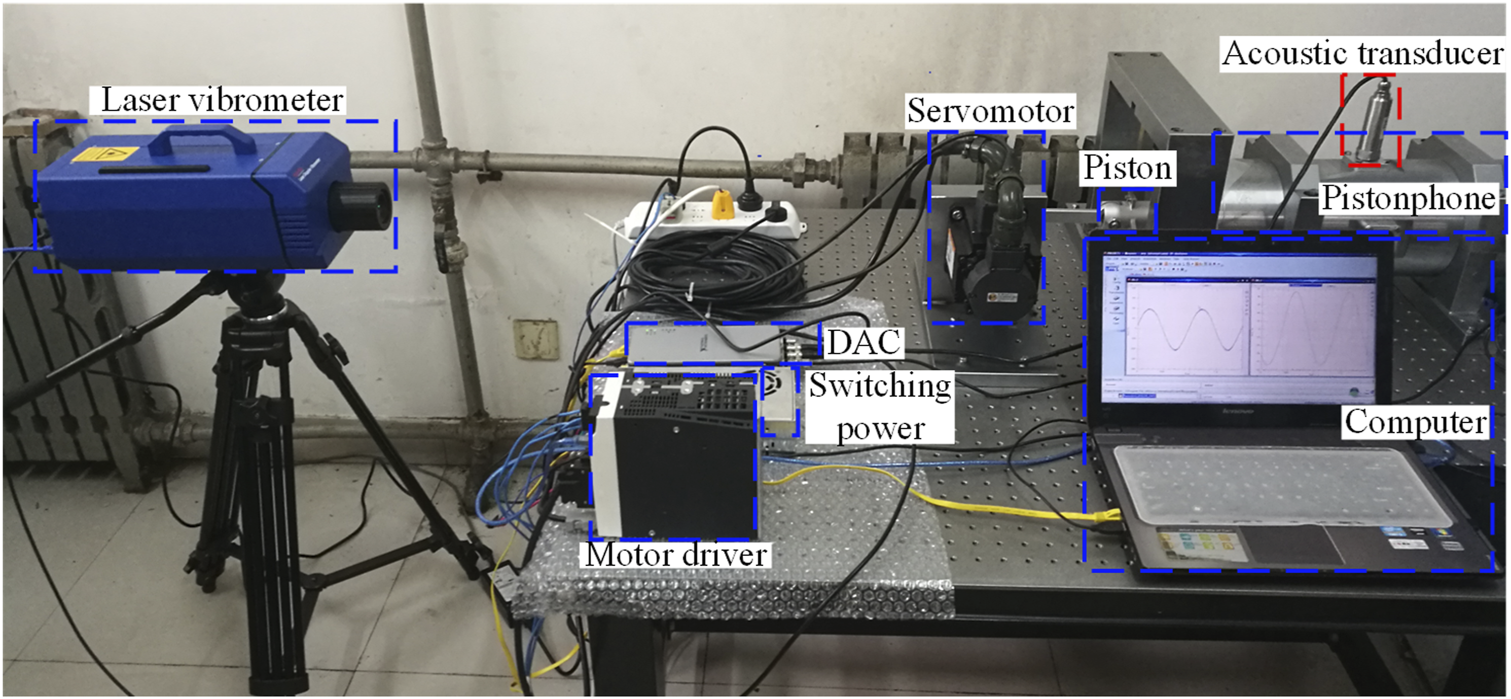
At infrasonic frequencies, the acoustic transducer itself is just like a “diaphragm excitated pistonphone” with a smaller chamber. A very important difference is when its vent end is inserted in the pistonphone (called vent in field calibration),
27
as shown in Figure 3, the calibrating sound pressure will invade the back-chamber. Or its vent end is inserted in the outside atmosphere (called vent out field calibration), so that the residual sound pressure outside the vent is zero. Difference between vent in field and vent out field calibrations.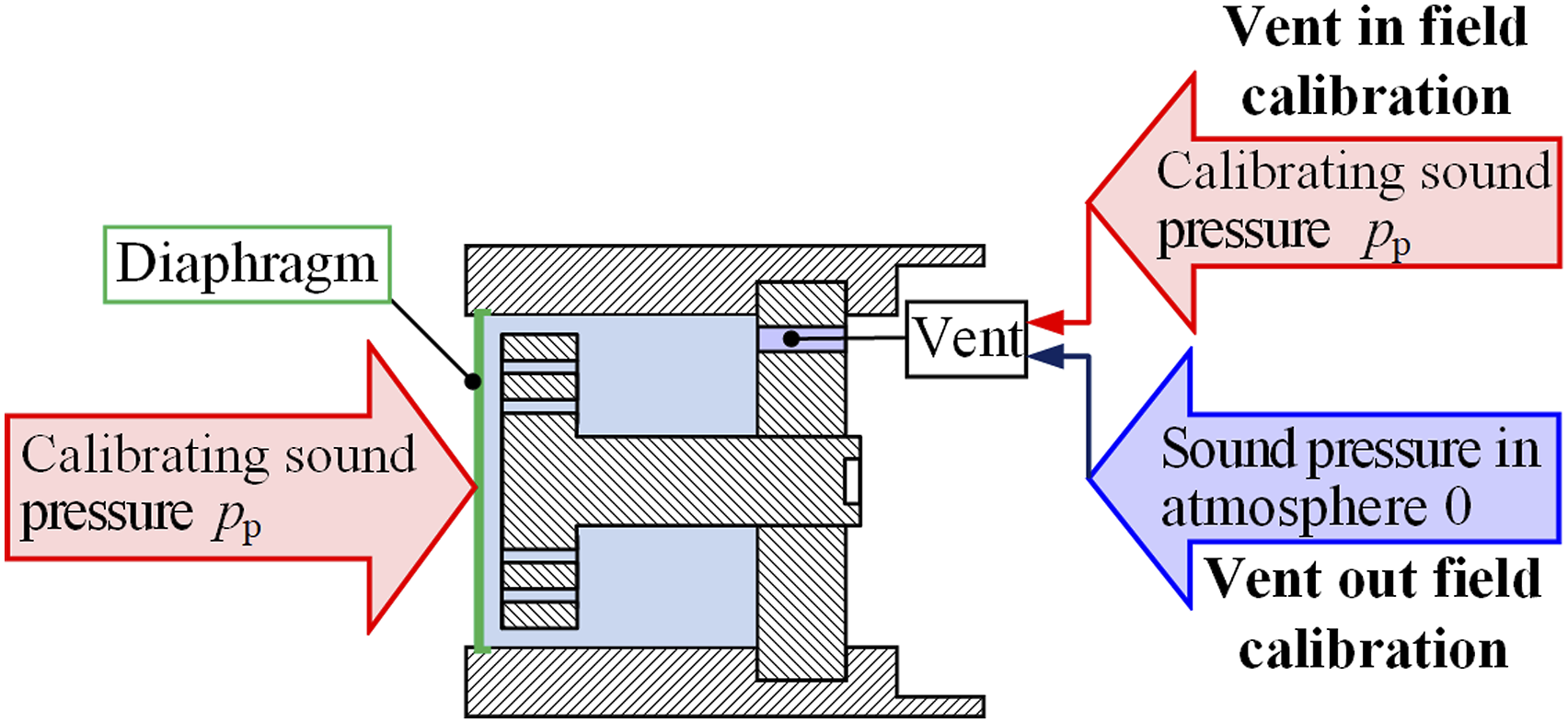
For vent in field calibrations, the amplitude of the generated sound pressure in the back-chamber of the acoustic transducer is given by
27
These sound pressures, equation (1) and (2), acting on both sides of the diaphragm, will be balanced with its elastic force, and satisfies kmξma = αm (

Particularly, for vent out field calibrations, subitem
When the electrical characteristics of the acoustic transducer and its preamplifier are considered as ideal, the output voltage of acoustic transducer is in linear relationship with the diaphragm deformation. Thus divide the diaphragm deformation with the calibrating sound pressure, equation (1), explicit sensitivity models of acoustic transducer for both vent in field and vent out field calibrations are obtained as

In a further step, exponential forms of the complex
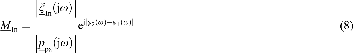
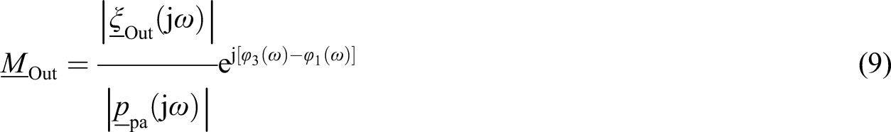
It can be seen that the low frequency sensitivities of acoustic transducers are complex quantities, so that the phase sensitivity variations will exist.
Sound pressure variation
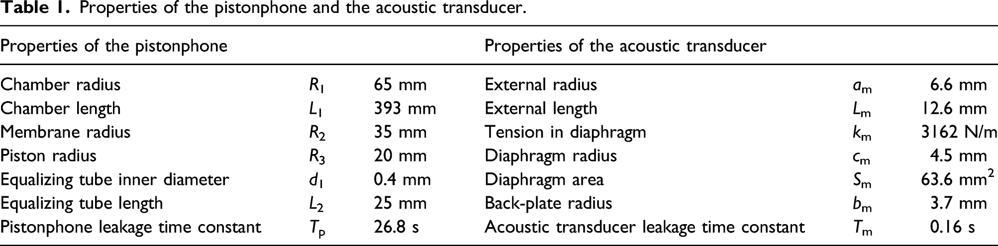
Independent sound pressure variations both in the pistonphone and the acoustic transducer are studied at first. Constant displacement excitations of 1.36 mm and 7.2 × 10⁻⁴ mm are applied on piston and diaphragm especially, to produce ideal 127 dB (re. 20 μPa) sound pressures in the pistonphone and the acoustic transducer. Their sectional structures are given in Figure 4. Relevant parameters for calculations are listed in Table 1. (a) Sectional view of the pistonphone. (b) Sectional view of the acoustic transducer. Properties of the pistonphone and the acoustic transducer.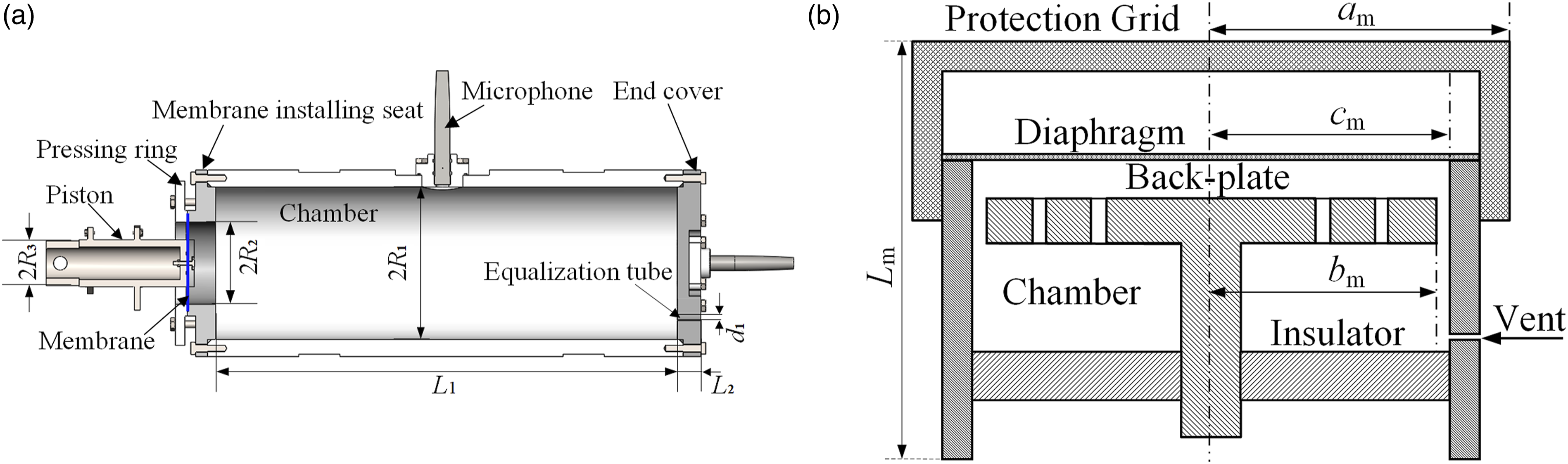
For the acoustic transducer, subitem
Sound pressure amplitude and phase difference of the sound pressure relative to displacement excitation for both the pistonphone (pist.) and the acoustic transducer (ac_tr.).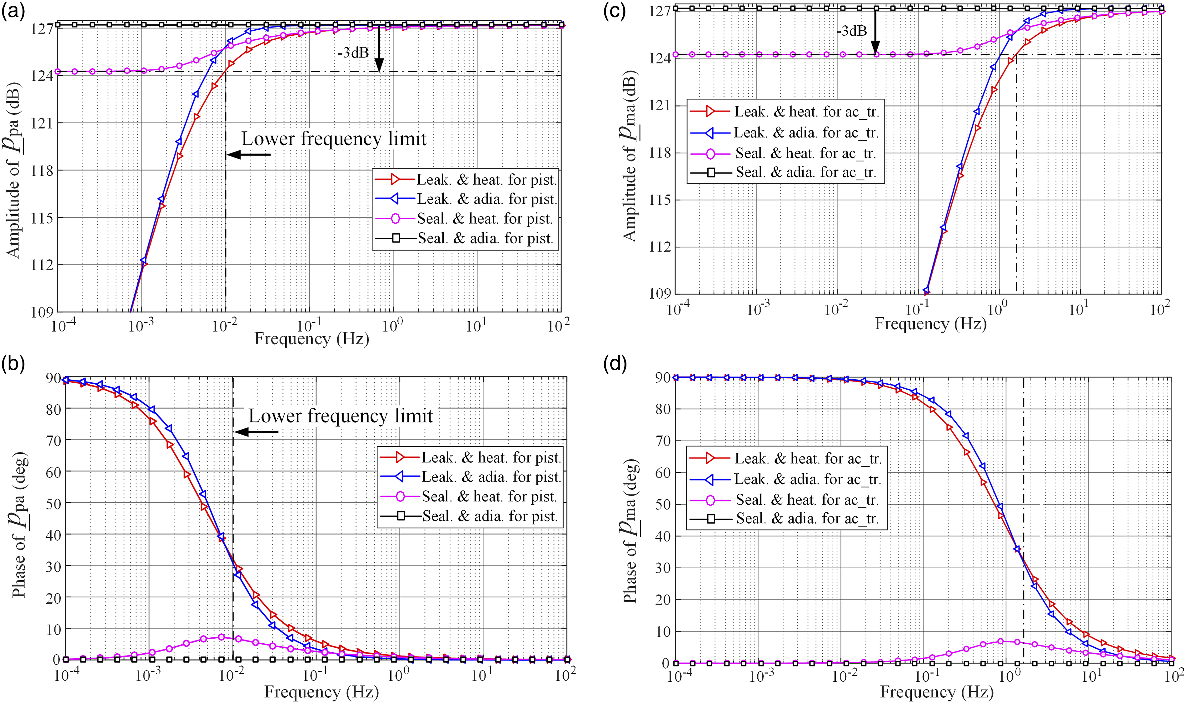
The amplitude response has already been studied in other papers, and is shown here only to compare the consistency of the influence factors acting on responses. Apparently can be seen from Figure 5 that the pressure leakage and heat conduction effect acting on the amplitude and phase responses happen simultaneously. The influence of the pressure leakage effect is obvious, and a 90° phase lead limit of the sound pressure relative to displacement excitation will happen. While the heat conduction effect only causes a −3 dB amplitude attenuation (characterized by Epv and Emv in equation (1) and (2), respectively, whose values all varies from the high frequency value 1 to low frequency value 0, and follows 20log10 (1/κ) ≈ −3 dB), and the phase difference only occurs at a small interval when the transition from high frequency adiabatic process to low frequency isothermal process happens.31–33 The specific mechanism for the occurrence of phase fluctuations will be analyzed in detail in the section “Interpretation on phase variation.”
Due to the smaller chamber and a relatively larger leakage path, the pressure leakage and heat conduction effect happen earlier in the acoustic transducer than in the pistonphone. So that the amplitude attenuation and phase lead happened at earlier frequencies. It can be considered that due to the second coupling mechanism, the acoustic transducer phase sensitivity will inevitably vary at low frequencies.
For the actual laser-pistonphone, the −3 dB amplitude attenuation is considered to determine the lower frequency limit of the pistonphone, that is, 0.01 Hz. Thus a 30° phase lead limit of the sound pressure relative to the displacement excitation will happen at low frequencies.
Sensitivity analysis of the acoustic transducer
The diaphragm deformation of the acoustic transducer should be obtained at first to study the sensitivity of the acoustic transducer. The parameters of the pistonphone still follow those given in Table 1, and the practical pressure leakage and heat conduction condition is selected for calculation. The influence of the acoustic transducer parameters acting on the frequency response of diaphragm deformation is studied to reveal the universal rule of sensitivity variations.
The leakage effect of the acoustic transducer is selected as completely sealed (labeled as seal.), 0.16 s time constant (large-leak.), 16 s constant (small-leak.), respectively. The heat conduction effect of acoustic transducer is selected as adiabatic (adia.), heat conduction (heat.), respectively.
According to above considerations, the deformation responses of the acoustic transducer diaphragm when its vent connected to the calibrating sound field is calculated according to equation (3). For vent out field calibrations, subitem Amplitude of the diaphragm deformation and the phase difference of diaphragm deformation relative to piston excitation.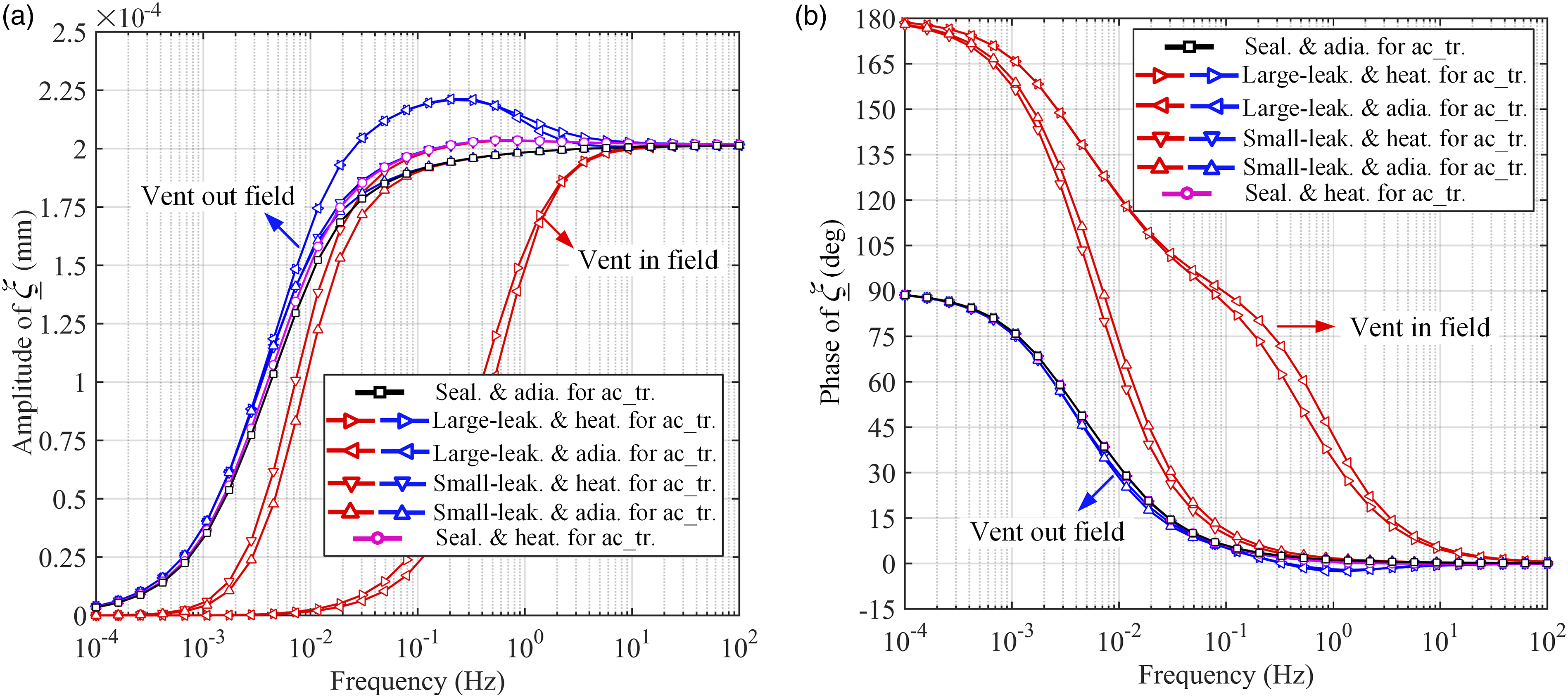
In terms of the amplitude response, the diaphragm deformations show very familiar attenuation for vent out field calibrations. The overall attenuation below 0.01 Hz comes from the attenuation of calibrating sound pressure in pistonphone. A smaller leakage loss of acoustic transducer helps to decrease the deformation difference between vent in field and vent out field calibrations, while the severe decrease for large-leakage condition in vent in field calibrations is caused by the invasion of calibrating sound pressure into acoustic transducer back-chamber.
In terms of the phase response, it is clear that the phase difference of diaphragm deformation relative to piston excitation for vent out field and vent in field calibrations have two different limits, as 90° and 180°, respectively. For vent out field calibrations, the phase response is rarely affected by properties of acoustic transducer, which means that the phase lead is caused by the sound pressure loss in pistonphone. That means, for a real pistonphone (“leak and heat”) based calibration, the piston excitation generates the calibrating sound pressure (90° phase lead at the maximum). If the acoustic transducer is “adia and seal,” the sound pressure in the acoustic transducer and the diaphragm deformation will be in phase (Figure 5(d)), so that the diaphragm deformation will has up to 90° phase lead of the piston excitation. Although for vent in field calibrations, the phase response is severely affected by the pressure leakage effect in the acoustic transducer, and a 180° phase lead limit is happened. The specific mechanism for the occurrence of phase fluctuations will be analyzed in detail in the section “Interpretation on phase variation.”
The amplitude sensitivity of acoustic transducer is then obtained by dividing the diaphragm deformation with the calibrating sound pressure in pistonphone. Although the phase sensitivity is obtained by subtracting the phase difference between the diaphragm deformation and the calibrating sound pressure. So that the acoustic transducer sensitivities for different conditions are shown in Figure 7. Amplitude and phase sensitivities of the acoustic transducer.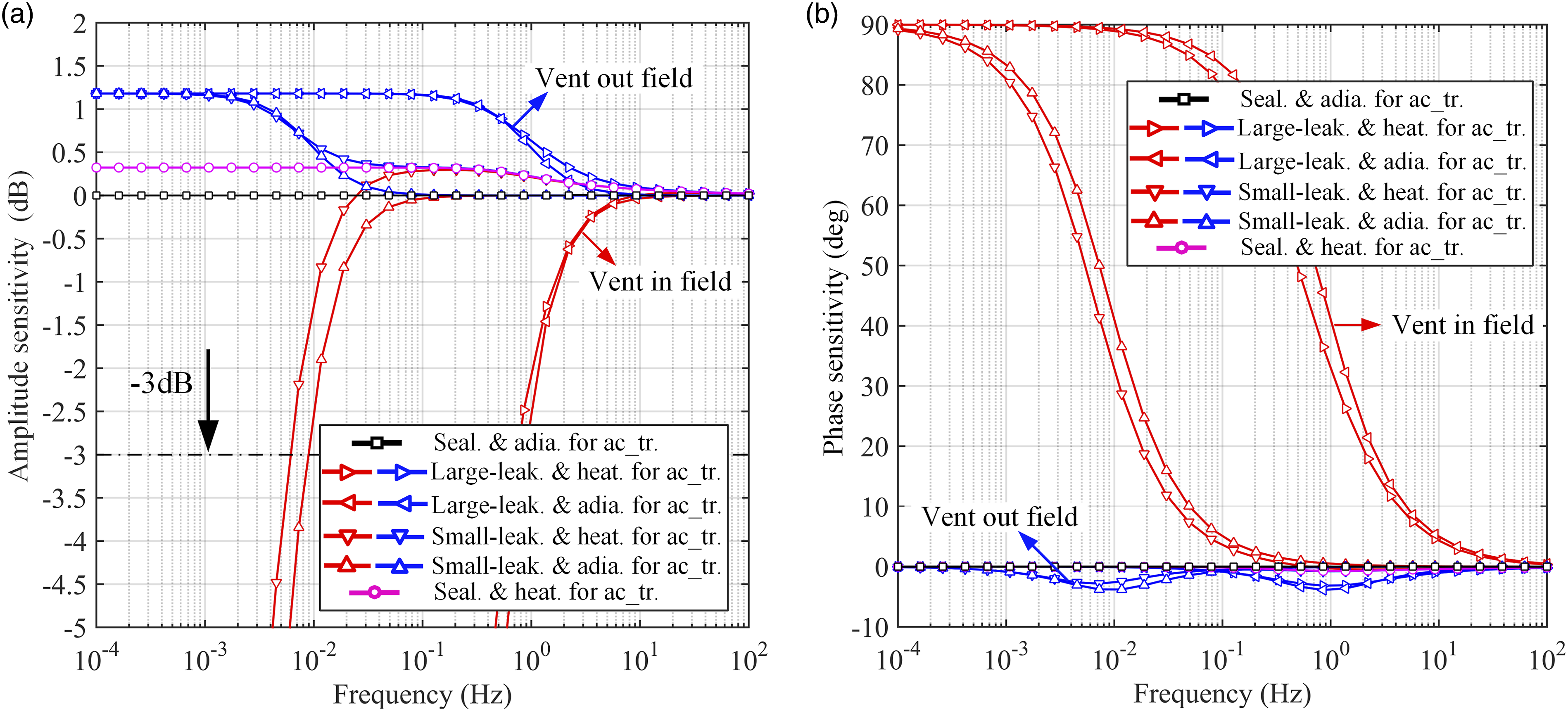
For vent out field calibrations, it can be seen that the amplitude sensitivity will be increased to a certain extent under the influence of pressure leakage and heat conduction effect of the acoustic transducer, but will not show attenuation as the diaphragm deformation response does. The phase sensitivity of the acoustic transducer is affected by the pressure leakage and heat conduction effect of the acoustic transducer, but the impact is very small with 5° phase lag limit, and happens only at certain frequency intervals.
For vent in field calibrations, due to the invasion of the calibrating sound pressure into the acoustic transducer back-chamber, the amplitude sensitivity is greatly reduced and the severe phase lead happens. In the meanwhile, the phase lead increases gradually along with frequency decreasing, and the limit is 90°. Both for amplitude and phase sensitivities, the turning trends occur at the same frequency, and the leakage effect plays a more important role than heat conduction effect.
On the other hand, according to the dual-coupling mechanism, the diaphragm deformation will also be affected by parameters of the pistonphone. Therefore, the phase frequency responses of the diaphragm deformation and the sensitivity of the acoustic transducer in two venting states are calculated according to equations (7)–(9), respectively, in which parameters of the pistonphone changes, and the realistic leakage and heat conduction condition is set for microphone, as shown in Figure 8. The sealing features of pistonphone are labeled as sealing (seal.) and leaking (leak.). (a) Phase difference of diaphragm deformation relative to the piston excitation; (b) Phase sensitivities of acoustic transducer.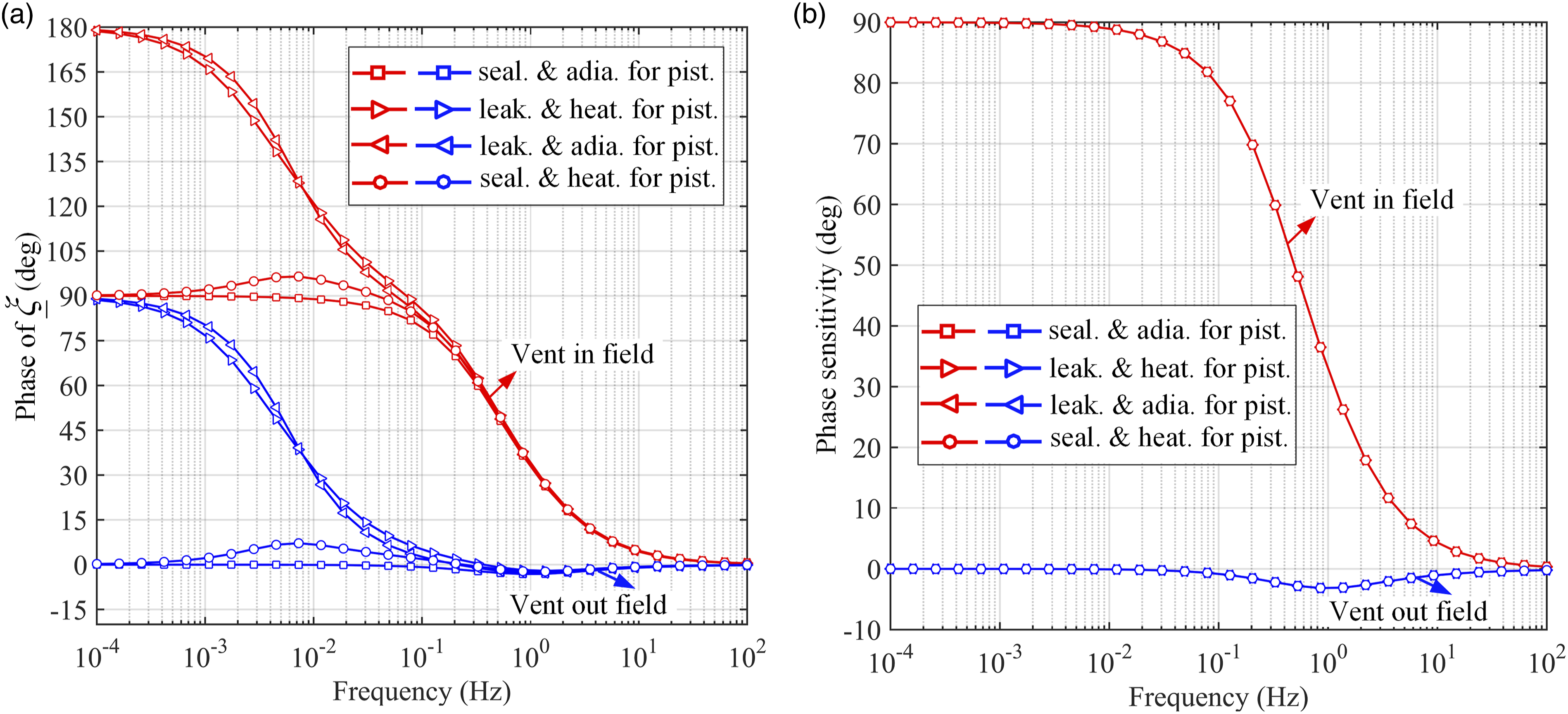
From Figure 8(a), it can be seen that the phase lead limit of 180° will happen for vent in field calibrations at very low frequencies when the incident sound pressure under leaking conditions is acted on the diaphragm. Although the phase lead limit of 90° will happen for vent out field calibration under the same condition of sound pressure excitation. Similarly, the phase lead limit of 90° and 0° will happen at two venting states when the incident sound pressure under sealing conditions acted on the diaphragm. Therefore, the sealing performance of the pistonphone is more important than the adiabatic performance.
From Figure 8(b), it can be concluded that the properties of pistonphone will not affect the phase sensitivity of microphone. The pressure leakage loss in the back-chamber of acoustic transducer is the dominating factor that affect its phase sensitivity for vent in field calibrations, while the influence of the heat conduction effect on the phase sensitivity is much less.
The simulation verification corresponding to this section, in which complex factors as viscosity and wave motion effect can be seen in the reference of Figure 16. 28 The results are consistent with this section, so that the correctness of the theoretical model can be proved.
Time domain interpretation on phase variation
The frequency domain calculations showed the phase variation phenomena quantitatively. But the physical mechanism of the phase variation still cannot be intuitively revealed. So that in this section, convolution method is used to analyze the output characteristics of generated sound pressures under displacement excitation, and the phase variation of the acoustic transducer is revealed.
From section Introduction, it can be concluded that the pressure leakage effect is the dominating factor that affects the sound pressure and sensitivity outputs. So that the leaking and adiabatic condition is only considered in this section.
When a step displacement excitation is applied on the piston, the air in pistonphone expands and compresses adiabatically, and is affected by the pressure leakage loss from the equalizing tube. The generated sound pressure in pistonphone follows

The piston displacement excitation is defined as ξpsin (ωt), then the displacement increment in the time of dt is given by xp(t) = ξpωcos (ωt). The calibrating sound pressure in pistonphone can be obtained from the convolution of piston displacement excitation with the unit step response function, as given by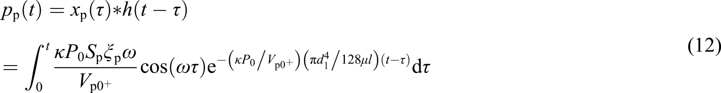
It can be derived that the calibrating sound pressure in pistonphone under the leaking and adiabatic condition is given by
The generated sound pressure in acoustic transducer back-chamber under the diaphragm deformation excitation also follows equation (13), only that the parameters of pistonphone should be replaced by those of the acoustic transducer. The amplitude of piston displacement is still 1.36 mm. The leakage time constants are selected as the measure value 26.8 s and a very large number (sealing). Waveforms of the calibrating sound pressure at 0.01 Hz, 1 Hz, and 100 Hz are calculated according to equation (13), as shown in Figure 9(a)–(c). Similarly, the amplitude of diaphragm deformation is still 7.2 × 10⁻⁴ mm, and the waveforms of generated sound pressures in acoustic transducer is calculated as shown in Figure 9(d)-(f). Waveforms of generated sound pressures in pistonphone and acoustic transducer at 0.01 Hz, 1 Hz, and 100 Hz, respectively.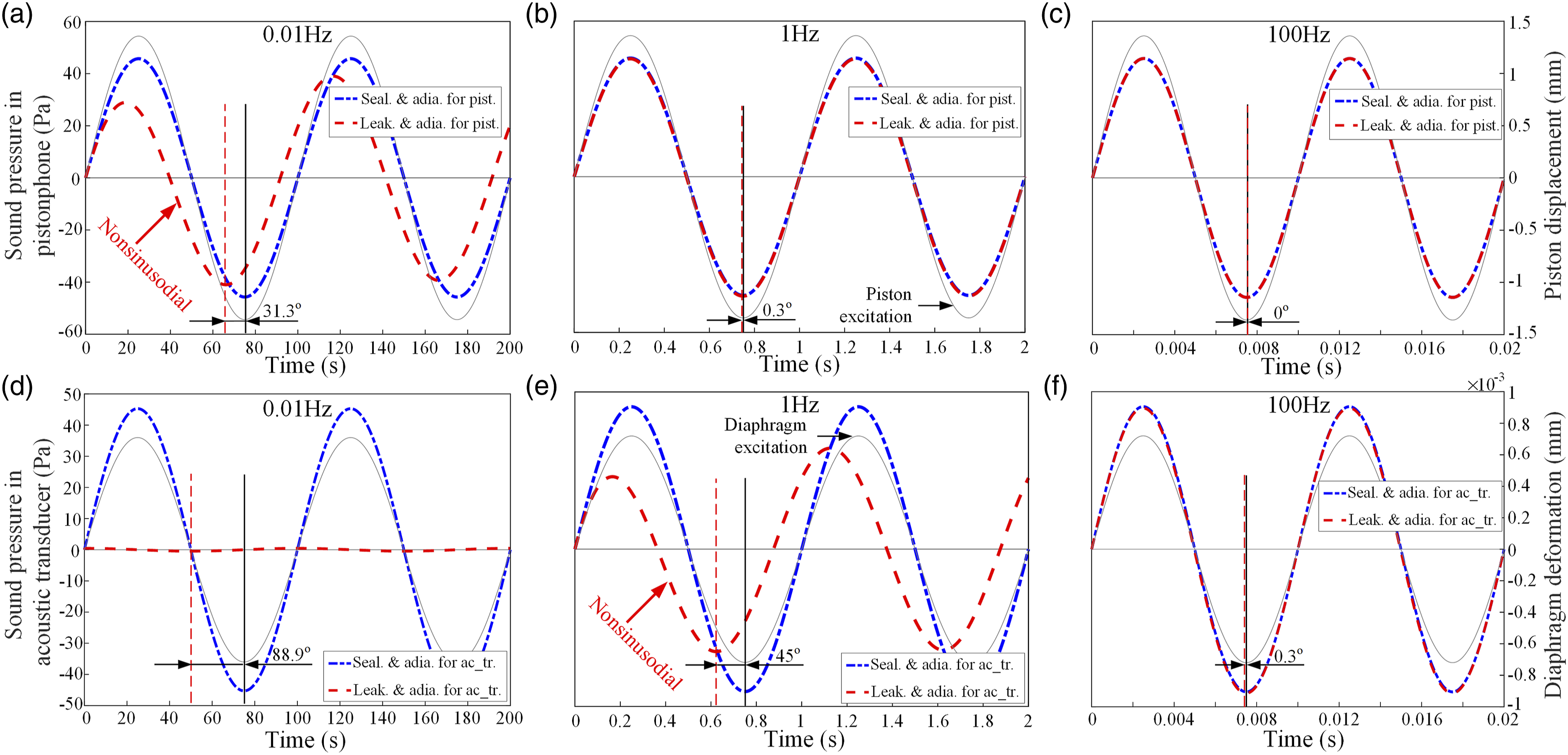
As shown in Figure 9, under the sealing condition, the generated sound pressures are synchronized with the displacement excitation. When leakage happens, sound pressures are greatly decreased at low frequencies as shown in Figure 9(a), (d) and (e). The phase angles are calculated and marked in figures, and the results are coincident with frequency domain results in Figure 5.
Particularly should be noted that their waveforms at low frequencies are not perfectly sinusoidal in the first circle, apparently can be seen in Figure 9(a) and (e), and causes the phase difference of sound pressure relative to displacement excitation. Let us specifically consider the first half period of the first circle, when the piston sinusoidally moves to its positive direction, the sound pressure increase is not enough to compensate the leakage loss and it starts to decrease. When the piston moves from this extreme position to negative direction, the air is all along being expanded to the negative value, particularly in no relation to the equilibrium position of the piston. Thus, the phase lead of the generated sound pressure relative to the excitation occur.
If we further considering the calibration process, for example, for vent out field calibration at 1 Hz, when the calibrating sound pressure in pistonphone start to decrease in its second 1/4 period of the first circle, the prematurely decreased sound pressure in acoustic transducer attracts the diaphragm to create even larger deformation, so that the phase lag of the diaphragm deformation relative to calibrating sound pressure occur, and the phase lag of acoustic transducer sensitivity is obtained. Comparatively for vent in field calibration at 1 Hz, the calibrating sound pressure invades into the acoustic transducer back-chamber, and induces earlier attenuation of diaphragm deformation, so that the severe phase lead is obtained. Based on above analysis, the mechanism of phase variation is revealed physically.
The simulation verification corresponding to this section, in which complex factors as viscosity, heat conduction and wave motion effect can be seen in the reference of Figure 6. 28 The results are consistent with this section, so that the correctness of the theoretical model can be proved.
Pistonphone optimization
In subsection Sensitivity analysis, it is found that the currently designed laser-pistonphone cannot fully calibrate the low frequency sensitivity of acoustic transducer with leakage time constant of larger than 16 s. However, there are urgent needs of acoustic transducers and specialized acoustic actuators for infrasound measurement at even lower frequencies. Therefore, it is necessary to further study the possibility of further extending the lower frequency limit of pistonphone down to 0.001 Hz.
Corrections at typical frequencies for the laser-pistonphone.
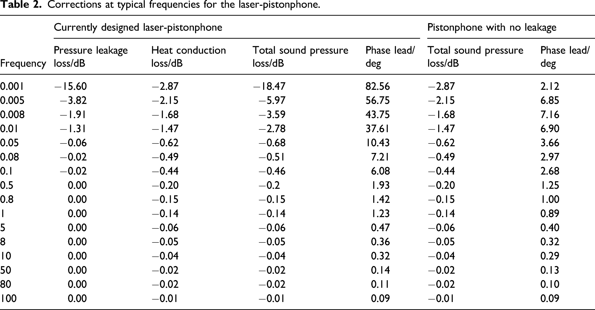
At frequencies below 0.01 Hz, the correction values of pressure leakage and heat conduction effects are comparative. But technically speaking, the improvement of pressure leakage effect has easier solutions than heat conduction effect. The static pressure equalizing mechanism is always needed to ensure that the acoustic transducer diaphragm is not subjected to unwanted static pressure difference. But during calibrating, the equalizing tube induced pressure leakage loss is not wanted. Therefore, a self-locking gas connector can be used to realize open-close switch, thus there will be no pressure leakage loss. The amplitude loss and phase lead values of the pistonphone with no leakage are also calculated as shown in Table 2.
It can be seen that when pressure leakage loss in pistonphone is avoided, the amplitude loss of calibrating sound pressure at 0.001 Hz is smaller than 3 dB, and fully satisfies the calibration demand. In the meanwhile, the phase lead of the calibrating sound pressure relative to piston displacement excitation is smaller than 8°. So that in the general accuracy, the phase difference between the acoustic transducer voltage output and the piston displacement excitation can be considered as the phase sensitivity of acoustic transducer.
Conclusions
There are urgent needs of the phase calibration of infrasonic acoustic transducers to locate large-scale natural and manmade activities. The currently derived sensitivity models provide us with a means of studying the acoustic transducer phase response theoretically, and is studied here in detail. The main conclusions are given as below:
The phase difference of sound pressure relative to displacement excitation are first studied, and found that the pressure leakage and heat conduction effects in acoustic transducer will affect the amplitude and phase of sound pressure simultaneously. The influence of pressure leakage effect is severe, and will cause a 90° phase lead limit. Although the heat conduction effect will only cause an 8° phase lead limit when adiabatic to isothermal transformation happens.
Acoustic transducer phase sensitivities are then studied by comparing acoustic transducer diaphragm deformation with calibrating sound pressure, and found that for vent out field calibrations, the phase sensitivity has 5° phase lag limit variation affected by the pressure leakage and heat conduction loss in acoustic transducer. Although for vent in field calibrations, due to the invasion of calibrating sound pressure into acoustic transducer back-chamber, severe phase lead with 90° limit will happen. The pressure leakage effect plays the dominating role than the heat conduction effect.
It is revealed that due to severe pressure leakage loss at low frequencies, when the displacement excitation moves from this extreme position to negative direction, the air is all along being expanded or compressed, but in no relation to the equilibrium position of excitation. Thus, the phase lead of the sound pressure relative to excitation occur. The amplitude attenuation and phase lead of sound pressure in acoustic transducer happens earlier than in pistonphone, so that the acoustic transducer phase sensitivity will vary at low frequencies.
Due to distinct and variable sensitivities of acoustic transducer for vent in field and vent out field calibrations. It is recommended to conduct the primary phase sensitivity calibration of acoustic transducer before serving.
Footnotes
Author Contributions
All authors discussed the results and contributed to the final manuscript. Aibing Liu, Di Liu and Fan Zhang contributed to theoretical analysis. Di Liu, Aibing Liu, and Fan Zhang analyzed the data. Aibing Liu wrote the paper. Huiheng Wang, Jixing Wu, Feng Chen, Xiujuan Feng modified the manuscript.
Declaration of conflicting interests
The author(s) declared no potential conflicts of interest with respect to the research, authorship, and/or publication of this article.
Funding
The author(s) disclosed receipt of the following financial support for the research, authorship, and/or publication of this article: We acknowledge the support received from the National Natural Science Foundation of China (NO. 51705298, NO. 52075513).
Data availability statement
The data supporting the conclusion of the article are shown in the relevant figures and tables in the article. The data used to support the findings of this study are available from the corresponding author upon request.