
Abstract
In this paper, in order to reduce the influence of vibration and noise generated by the motor in rock cotton centrifuges on the quality of the output fiber and the damage to the operator’s hearing, it is meaningful to analyze and optimize the vibration and noise. A high-speed magnetic suspension motor is proposed for the rock cotton centrifuge in the paper. First, the motor model is established in Maxwell, the radial force density wave distributed in the air gap is calculated by the field solver, the main harmonic source is analyzed according to its FFT decomposition graph, and then the optimization scheme of short-range double-layer winding is determined. Second, the optimization scheme is analyzed in modal mode and harmonious response, and the vibration response spectrum of the motor stator is obtained. Finally, the electromagnetic noise characteristics of the motor are obtained through ANSYS acoustics simulation. The results show that the optimized motor noise has a reasonable level under the premise of ensuring electromagnetic performance.
Introduction
There is a more mature technology with the high power density and strong reliability for permanent magnet synchronous motor, which is being applied widely in more and more fields. The high-speed magnetic suspension rock wool centrifuge designed in this paper is based on the ordinary permanent magnet motor. Equipped with electromagnetic bearings at both ends, providing radial support force can make the motor achieve higher speed and longer life without mechanical friction. The main reason for the vibration and noise of the rock wool centrifuge is that the stator core caused by the radial electromagnetic force in its motor shrinks and expands at a certain frequency. The output spindle may constantly deviate from its center position and then be pulled back to the original position by the electromagnetic bearing, which makes the spindle yield uneven shaking. The shaking intensity is proportional to the strength of vibration. When the molten magma falls on the shaking spindle, uneven fibers will be produced, thus affecting the quality of the product. Furthermore, the noise caused by vibration will affect the hearing of the operator. Therefore, it is essential to suppress the vibration and noise of the motor.
In recent years, many researchers have paid attention to the vibration and noise in permanent magnet synchronous motor (PMSM), 1 switched reluctance motor, 2 induction motor, 3 and other hybrid electric vehicles. 4 Especially for the permanent magnet synchronous motor, the relative research has gained much more attention. The research of vibration and noise involves many aspects such as electromagnetic, structure, mechanics, sound field, and so on. In Ref. 5, a detailed finding of the mechanics of vibration and noise in PMSM is described by using electromagnetic and structural analyses. The effect of pole and slot combination on the vibration and noise in PMSM is evaluated in Ref. 6, and its analytical model for predicting noise and vibration is provided in Ref. 7. Besides, to effectively reduce magnitudes of vibration and noise of PMSM, the harmonic content and amplitude of the zeroth-order spatial electromagnetic force waves are investigated in Ref. 8. The amplitudes of the zeroth order and slot number order forces are considered based on the teeth chopping effect in Ref. 9. In Ref. 10, an improved rotor structure with auxiliary flux barriers for PMSM is proposed to weaken the electromagnetic vibration and noise by reducing the radial electromagnetic force. A multi-physics model for PMSM is established to analyze the electromagnetic vibration and noise, and two methodologies are designed to reduce the noise mitigation by optimizing magnetic forces in Ref. 11.
Moreover, a rotor step skewing model for PMSM is proposed to study the electromagnetic noise by analyzing the spectral characteristics of the low-order radial magnetic force in Ref. 12. In Ref. 13, the permanent magnet synchronous motor with variable-speed drives is introduced to investigate the stator vibration using an electromechanical impulse response. In Ref. 14, electromagnetic vibration and noise under different types of current harmonics are addressed by deriving the characteristics of radial electromagnetic force in PMSM. Similarly, the PMSM with different slot–pole combinations is studied to analyze electromagnetic vibration and noise in terms of a multi-physics model in Ref. 15. In addition, numerical prediction models are presented to investigate the electromagnetic vibration and noise of permanent-magnet direct current commutator motors when both rotor eccentricities and glue effects are involved in Ref. 16.
At present, the analysis of vibration and noise specifically for the high-speed magnetic suspension permanent magnet synchronous motor (HMS-PMSM) is relatively rare in the reference. Therefore, by referring to some of the analysis and optimization experiences of vibration and noise in the above papers, we investigated the vibration and noise of the rock wool centrifuges by optimizing the winding form. Through modal analysis, harmonic response analysis, and noise analysis, the rationality of the optimization scheme was verified. The contributions of the paper included three aspects: (1) A high-speed magnetic suspension motor was proposed for the rock cotton centrifuge, and the mathematical models of HMS-PMSM were established to investigate the vibration and noise; (2) based on Workbench, the modal analysis and harmonic response analysis of HMS-PMSM was carried out to analyze the main factors affecting the vibration noise of the motor; (3) the harmonic amplitude of the main order can be effectively decreased by selecting appropriate short-distance windings to reduce the vibration and noise of HMS-PMSM.
Structural parameters for HMS-PMSM in rock wool centrifuge
The rock wool centrifuge, whose physical structure is shown in Figure 1(a), is mainly composed of a roller device, wind ring system, glue spraying system, lubrication system, slide rail device, wheel device, distributor device, and accessories. Due to the requirement of the high speed and high quality, a high-speed magnetic suspension permanent magnet synchronous motor designed as shown in Figure 1(b) and Figure 1(c) is adopted in the roller device of the rock wool centrifuge, which plays an essential role in the quality of the produced fiber. In Figure 1(b), the overall structure of the HMS-PMSM is mainly composed of radial electromagnetic bearings, axial electromagnetic bearings, and a permanent magnet synchronous motor; in Figure 1(c), the profile structure of HMS-PMSM is described. The structure is designed to study the theory of motor vibration and noise in the next section. In the electrified state, the synthesis of magnetic forces generated by the radial electromagnetic bearings and axial electromagnetic bearings is controlled to realize the magnetic suspension of the motor rotor. In addition, to describe the structure of the radial magnetic bearing clearly, the section view of the radial magnetic bearing is depicted in Figure 1(d). It mainly includes stator, rotor, and control coil, where the stator is composed of stator magnetic yoke and eight uniformly distributed stator magnetic poles. The one-side air gap length of the magnetic bearing is 1 mm. The structure of rock wool centrifuge. a) Physical structure; b) overall structure of the motor; c) profile structure of the motor; d) the structure of the radial magnetic bearing.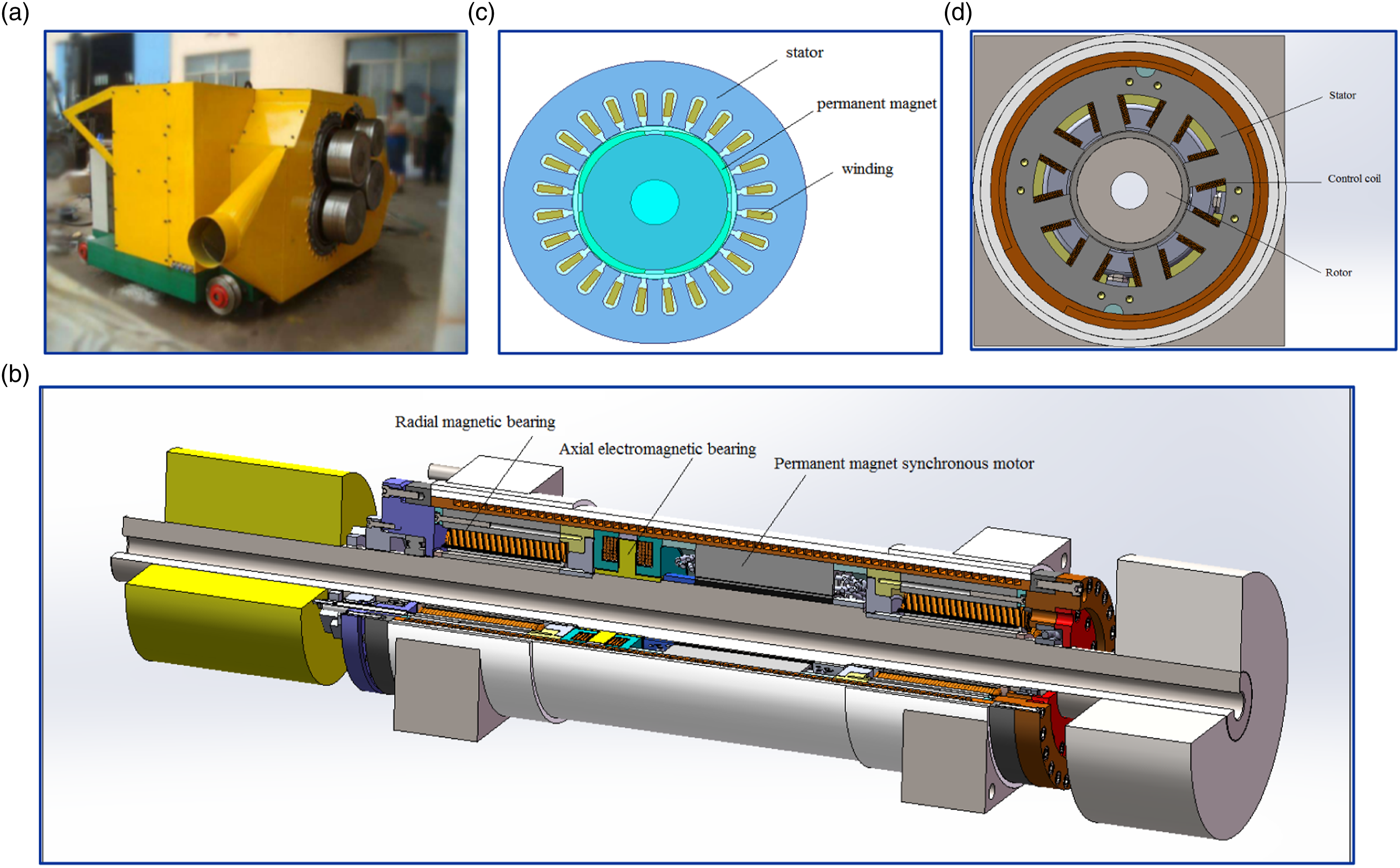
Parameters for the HMS-PMSM.
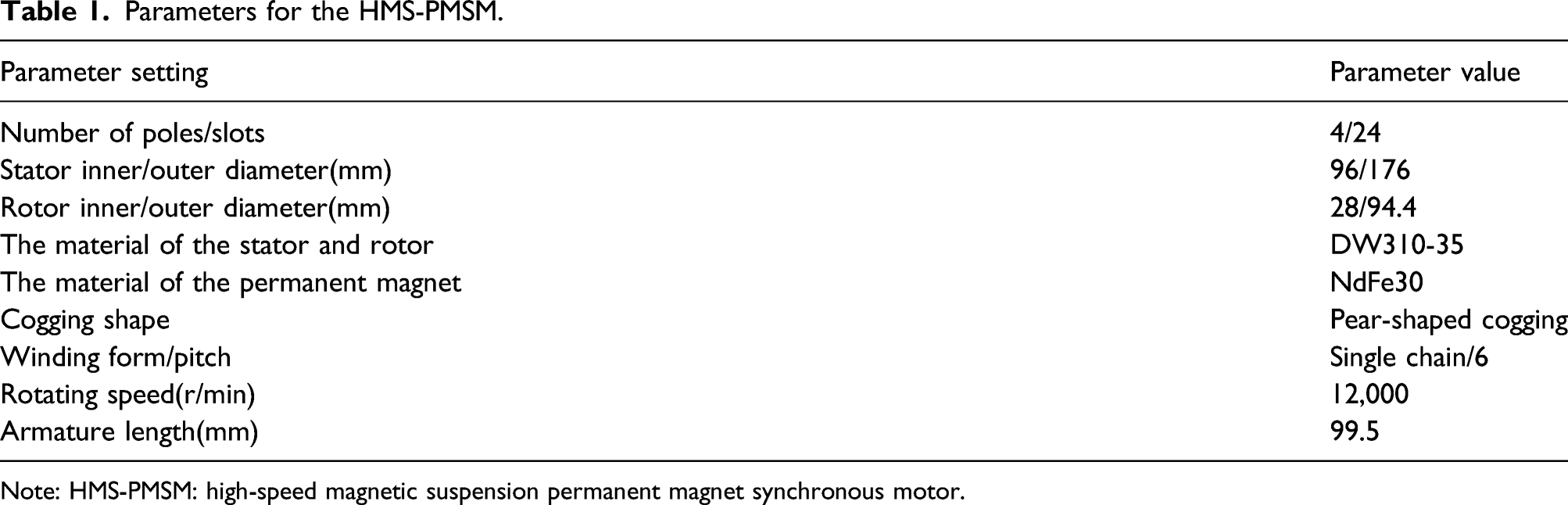
Note: HMS-PMSM: high-speed magnetic suspension permanent magnet synchronous motor.
Analysis theory of motor vibration and noise
Air gap magnetic conductivity
Affected by the slotting of the motor, the air gap magnetic conductivity not only has an average component but also needs to be superimposed on the alternating components of each harmonic. Therefore, the air gap magnetic conductivity can be expressed as
Armature magnetomotive force
The armature magnetomotive force is a pulsating magnetomotive force whose sine distribution in space changes according to the sine law with time. It can be decomposed into two rotating magnetomotive force components. The amplitude of each rotating magnetomotive force is half of the amplitude of the pulsed magnetomotive force. They have the same rotation speed, but the rotation direction is opposite, called positive and negative rotation magnetomotive force, which can be expressed as

Permanent magnet magnetomotive force
The permanent magnetomotive force is a space wave, which is excited by the permanent magnet and formed during the rotation of the rotor. Therefore, the speed of each harmonic is consistent with the speed of the composite wave, that is, the permanent magnetomotive force can be expressed as
Maxwell stress tensor
Motor noise is mainly produced by the shrinkage and expansion of the stator core caused by the radial electromagnetic force. The radial electromagnetic force can be expressed by the Maxwell stress tensor formula
Since the tangential magnetic induction intensity is negligible compared to the radial magnetic induction, the formula (5) can be simplified as
The magnetic induction intensity is generated by the magnetomotive force acting on the magnetic conductivity, so the radial magnetic induction intensity of the motor can be expressed as
Substituting formulas (1), (2), (3), (4), and (7) into (6), we have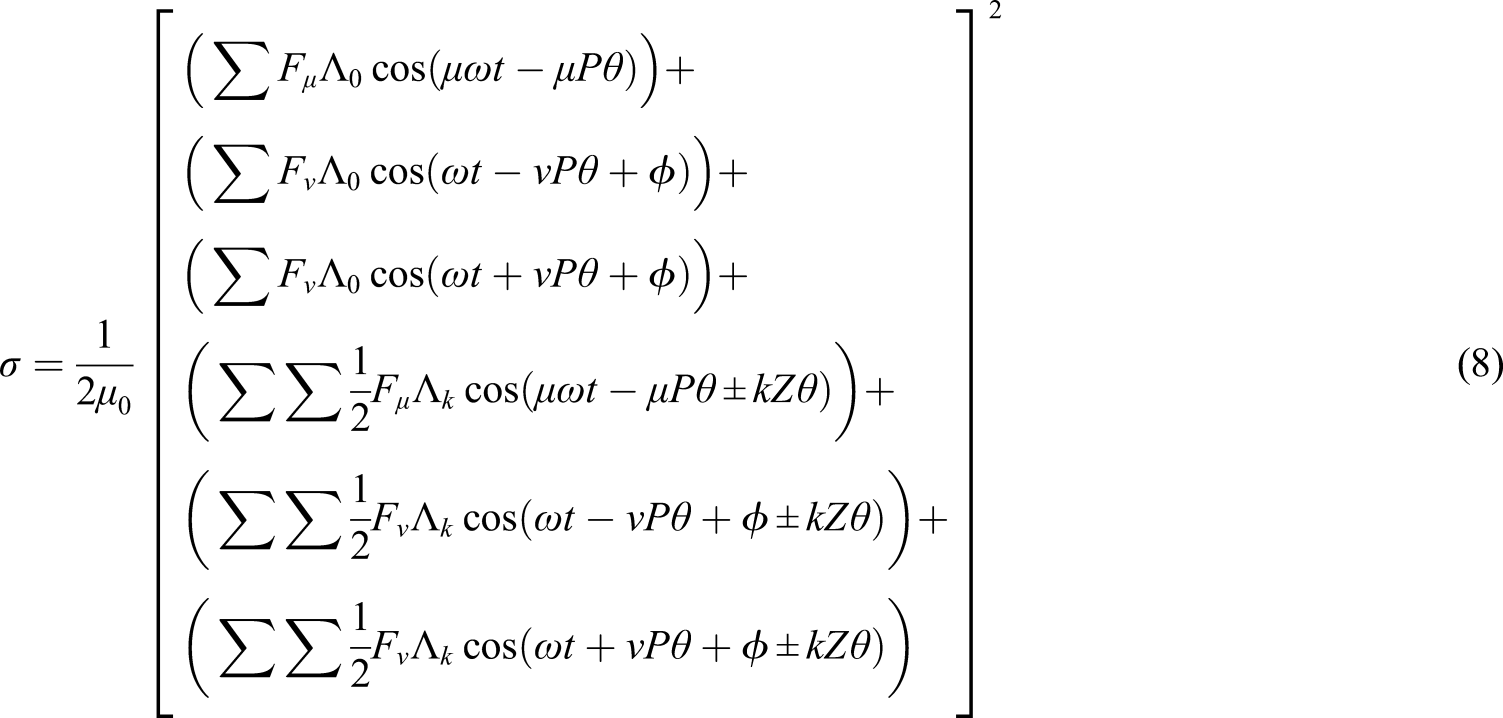
Electromagnetic simulation analysis based on Maxwell
It can be seen from formula (8) that parameters such as magnetic induction, magnetomotive force, and the number of slot poles are the key parameters for motor vibration and noise. The following is based on Maxwell’s software to simulate and analyze their distribution rules and optimize them.
Radial force density wave simulation
The radial electromagnetic force in the air gap has the direct effect on vibration and noise. It is affected by the combined effect of the time harmonics generated by the armature magnetomotive force and the space harmonics generated by the permanent magnet magnetomotive force. To optimize the motor design regarding the vibration and noise of HMS-PMSM, it is necessary to conduct a detailed analysis of the radial electromagnetic force density wave.
Since the amplitude of the radial force density wave is proportional to the amplitude of the vibration, it is necessary to conduct 2D FFT decomposition of the radial force density wave to analyze which order of harmonics has the most significant influence on the motor’s vibration. The radial force density wave is calculated in the field solver along the air gap according to formula (6), as shown in Figure 2. Radial force density diagram.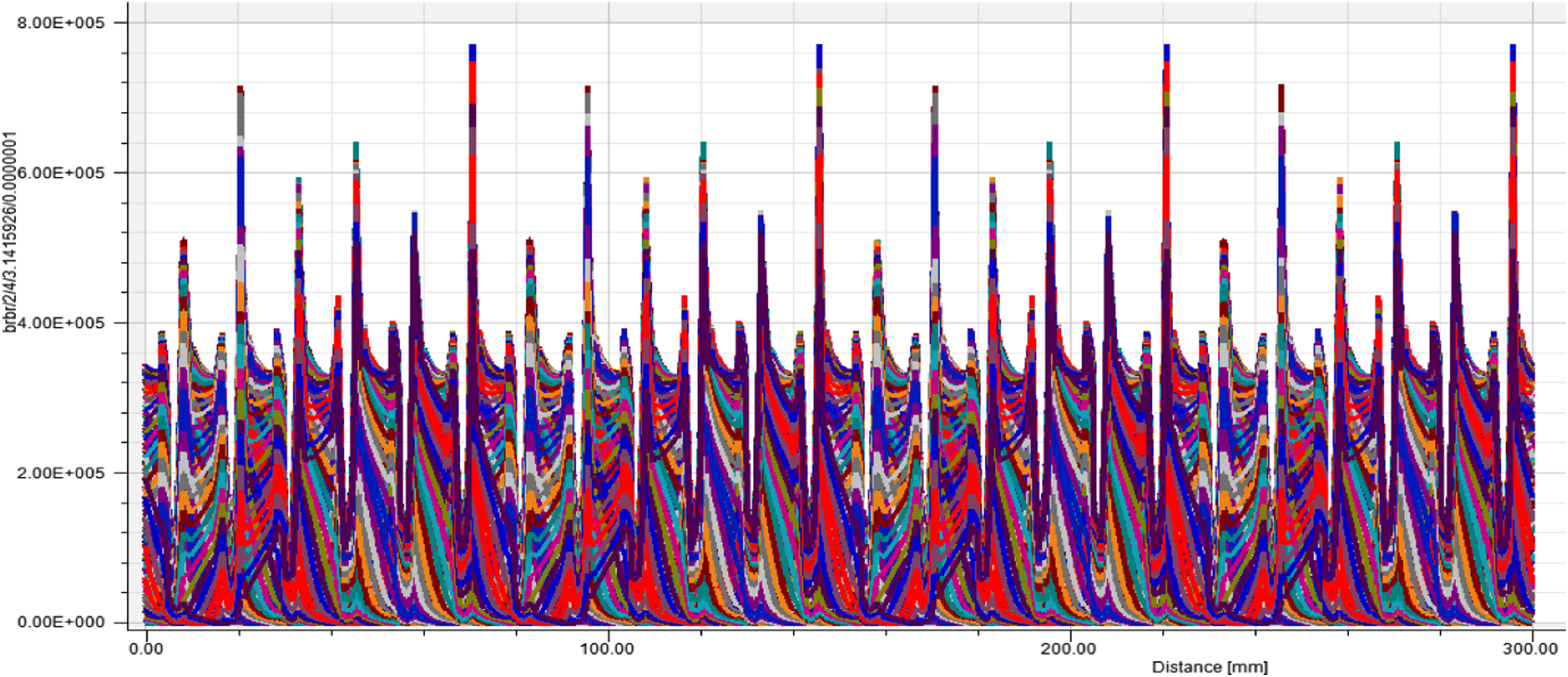
It can be seen that the peak value of the radial force density waveform is relatively high. In order to further analyze the characteristics of the waveform, the Fourier decomposition of the radial force density wave is carried out to observe the force density wave amplitude at different orders and times, as shown in Figure 3. FFT decomposition diagram of the radial force density wave.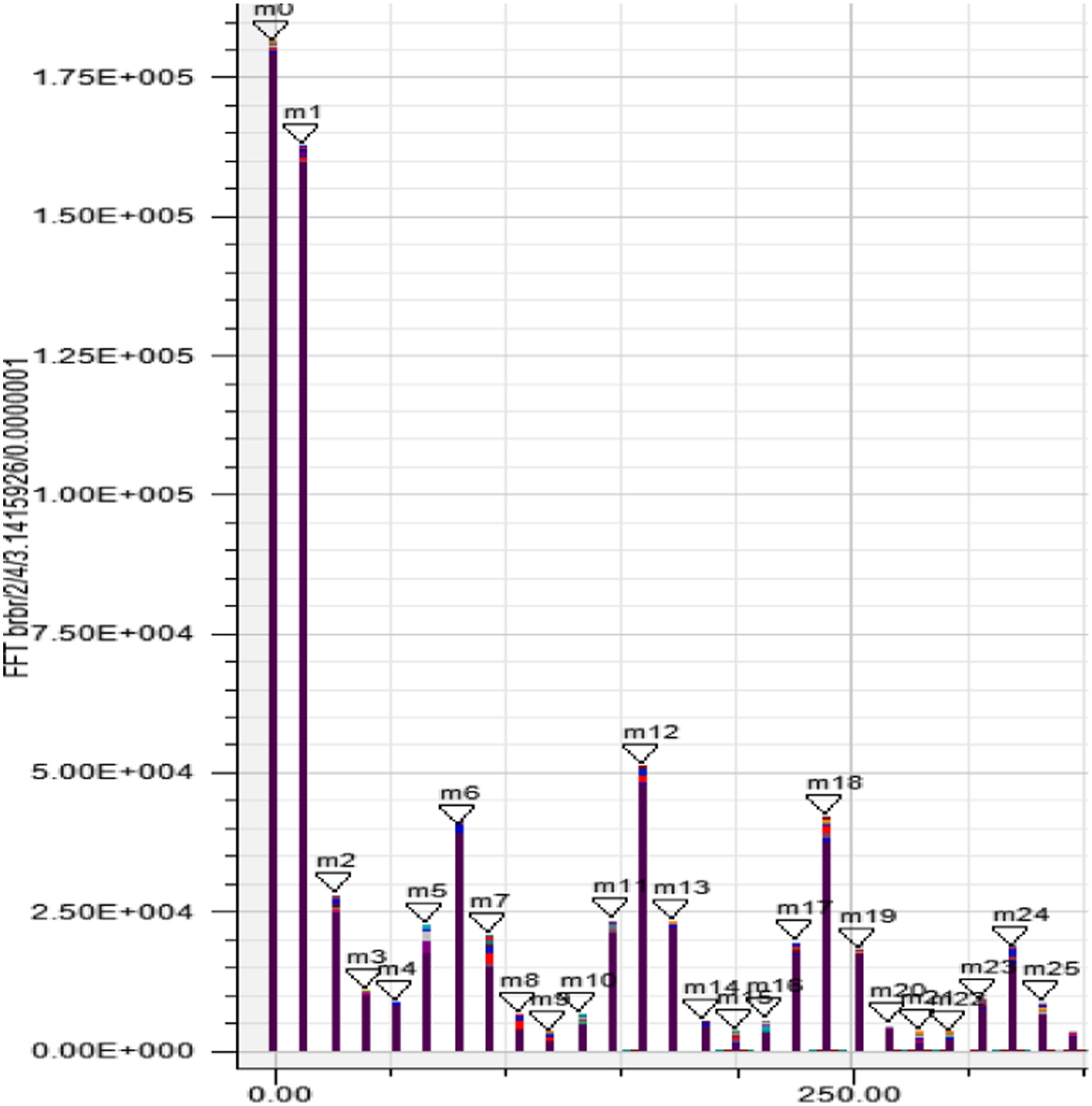
It can be seen from the figure that the force density wave of the same order has different orders of time harmonics. With the increase of the order, its force density amplitude shows a rapid decay trend, which means that the vibration trend becomes weaker. The influence of higher-order harmonics on the motor is also minimal. Therefore, focusing on the analysis of the force density waves of the first 20 orders, it can be concluded that the amplitudes of m0, m1, m2, m12, and m18 are relatively high. The specific order after FFT decomposition can be calculated by the following formula
Substituting the abscissas of the above-mentioned force density waves of various orders with larger amplitudes into the above formula, (1) The constant part of the radial force density wave is generated by the fundamental magnetic field: (2) The radial electromagnetic force density wave is produced by the magnetic field of the stator winding and permanent magnet magnetomotive force: (3) The radial electromagnetic force density wave is produced by stator air gap-tooth harmonic of magnetic conductivity and harmonic magnetic field of permanent magnet magnetomotive force:
Optimization design of the motor
It can be seen from Figure 3 that the harmonic amplitudes of m0 and m1 far exceed the amplitudes of other orders. The above analysis shows that m0 is the constant part of the radial force density wave generated by the fundamental magnetic field; m1 is generated by the interaction with the magnetomotive force harmonics of the permanent magnets and the stator winding; thus, the optimized designing of the motor is focused on its winding structure: winding form/pitch is double chain/4, and the armature length is 100 mm.
The improved calculation results are substituted into Maxwell for simulation. The obtained radial force density wave diagram and FFT decomposition diagram are shown in Figure 4 and Figure 5. Radial force density diagram after optimization. FFT decomposition diagram of radial force density after optimization.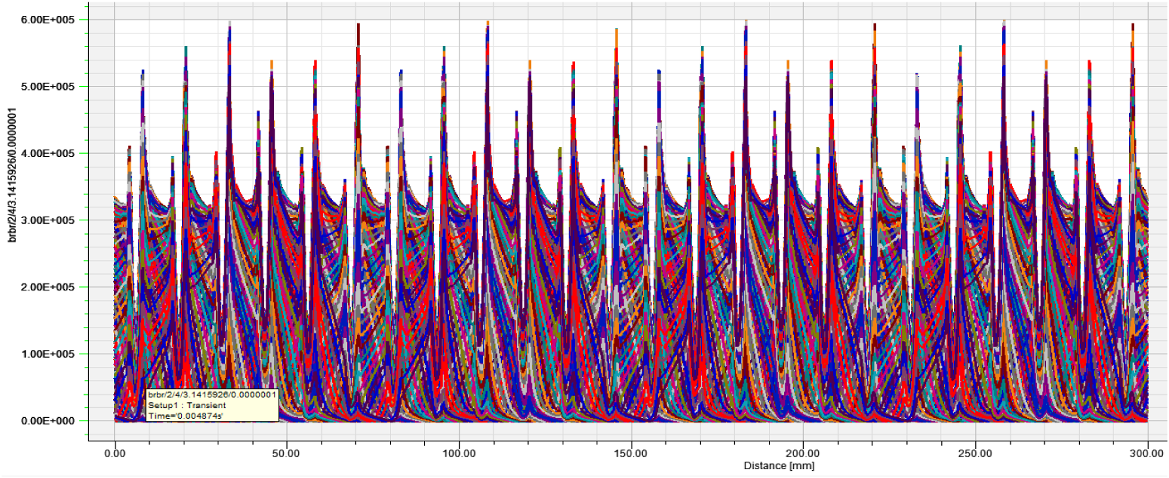
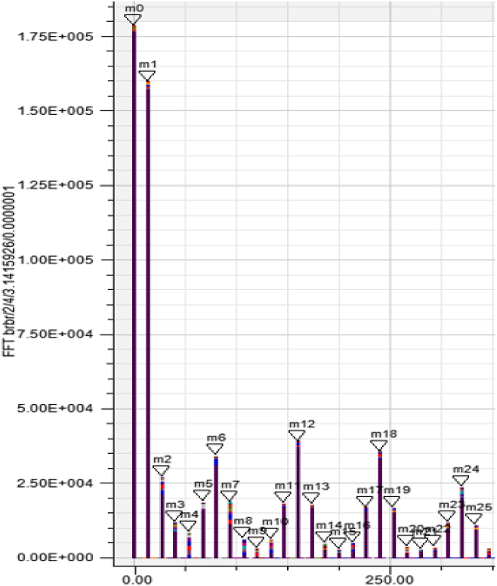
It can be seen that the peak value of the optimized radial force density map is significantly lower than that before the optimization. Observing the FFT decomposition diagram again, it can be found that the amplitudes of m0, m1, m2, m12, and m18, which have higher amplitudes in the low-order harmonics, have significantly decreased. Since each order is superimposed with time harmonics, it is impossible to observe the amplitude of the force density wave at different times and different orders from the FFT decomposition diagram alone. Therefore, the force density wave is displayed in three dimensions, before and after optimization. The three-dimensional diagrams are shown in Figure 6. 3D diagram of radial force density. (a) Not-optimized result. (b) Optimized result.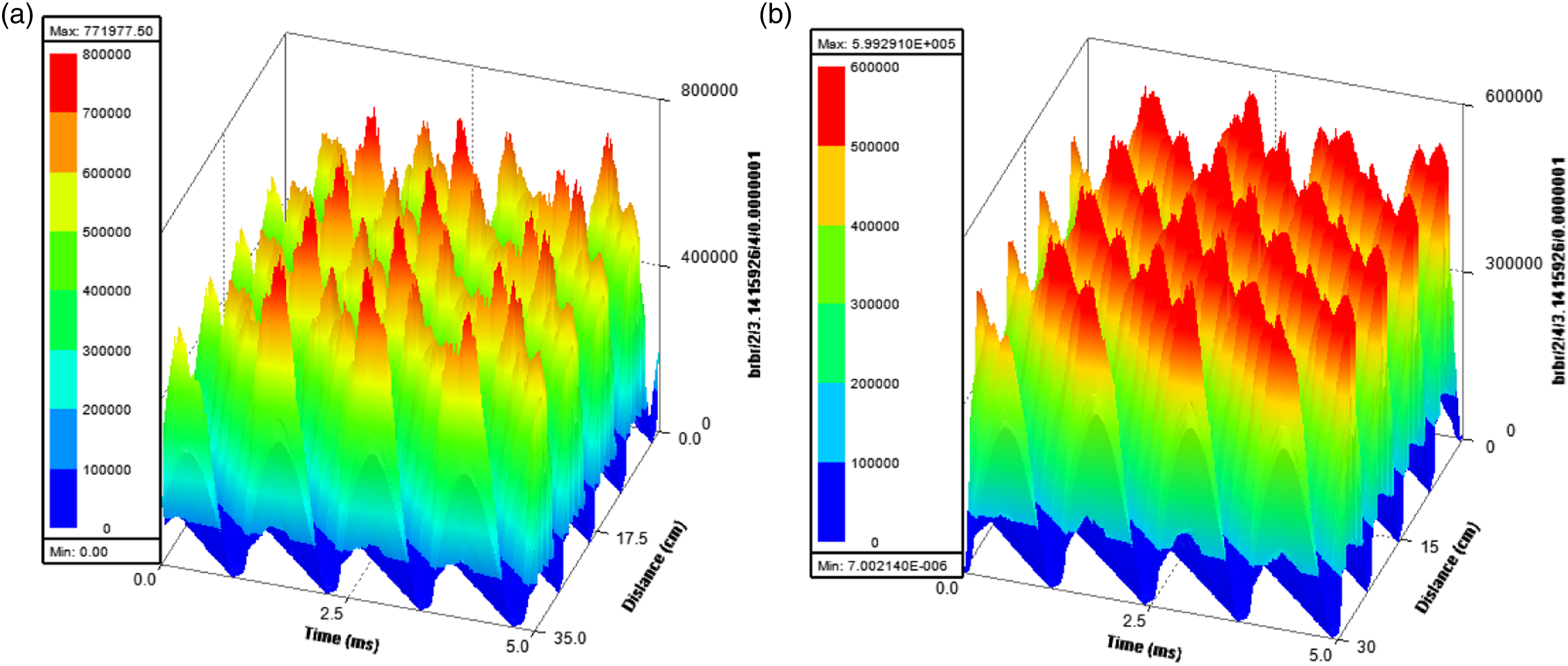
Vibration analysis based on workbench
Before performing modal analysis and harmonic response analysis, it is necessary to set the boundary conditions and force conditions regarding the stator model in workbench software. First, the radial electromagnetic force generated by the electromagnetic bearings has directly been applied to each stator’s teeth. In order to accurately simulate the force of the stator, all stator teeth were selected as the forced object, and the direction of the force was set as the radial direction. Then, six through-holes were punched evenly around the stator as fixed constraints to investigate the modal and harmonic response analysis. The boundary conditions of the stator model are shown in Figure 7. Boundary conditions of the stator model. (a) 1st order natural frequency 8755.8HZ. (b) 2nd order natural frequency 8925.8HZ. (c) 3rd order natural frequency 8929.7HZ. (d) 4th order natural frequency 9273HZ. (e) 5th order natural frequency 9274HZ. (f) 6th order natural frequency 9450HZ.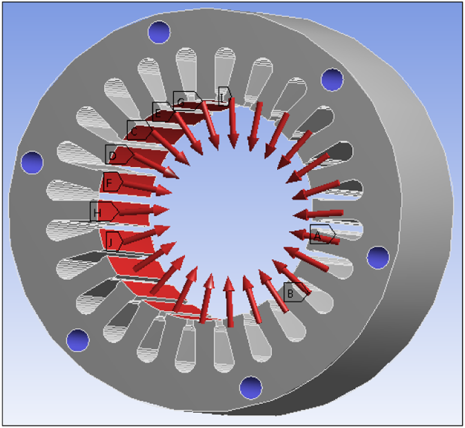
Modal analysis
When the frequency of electromagnetic force vibration is close to the natural frequency of the motor system, the motor will resonate. Resonance has a significant influence on the motor system, causing huge noise and reducing the service life of the motor. In order to avoid resonance in the design process, it is necessary to perform a modal analysis on the stator and calculate its natural frequency. Figure 8 shows the modal vibration shape of the motor stator at the first 6-order natural frequencies calculated through Workbench simulation analysis. Stator mode vibration shape diagram.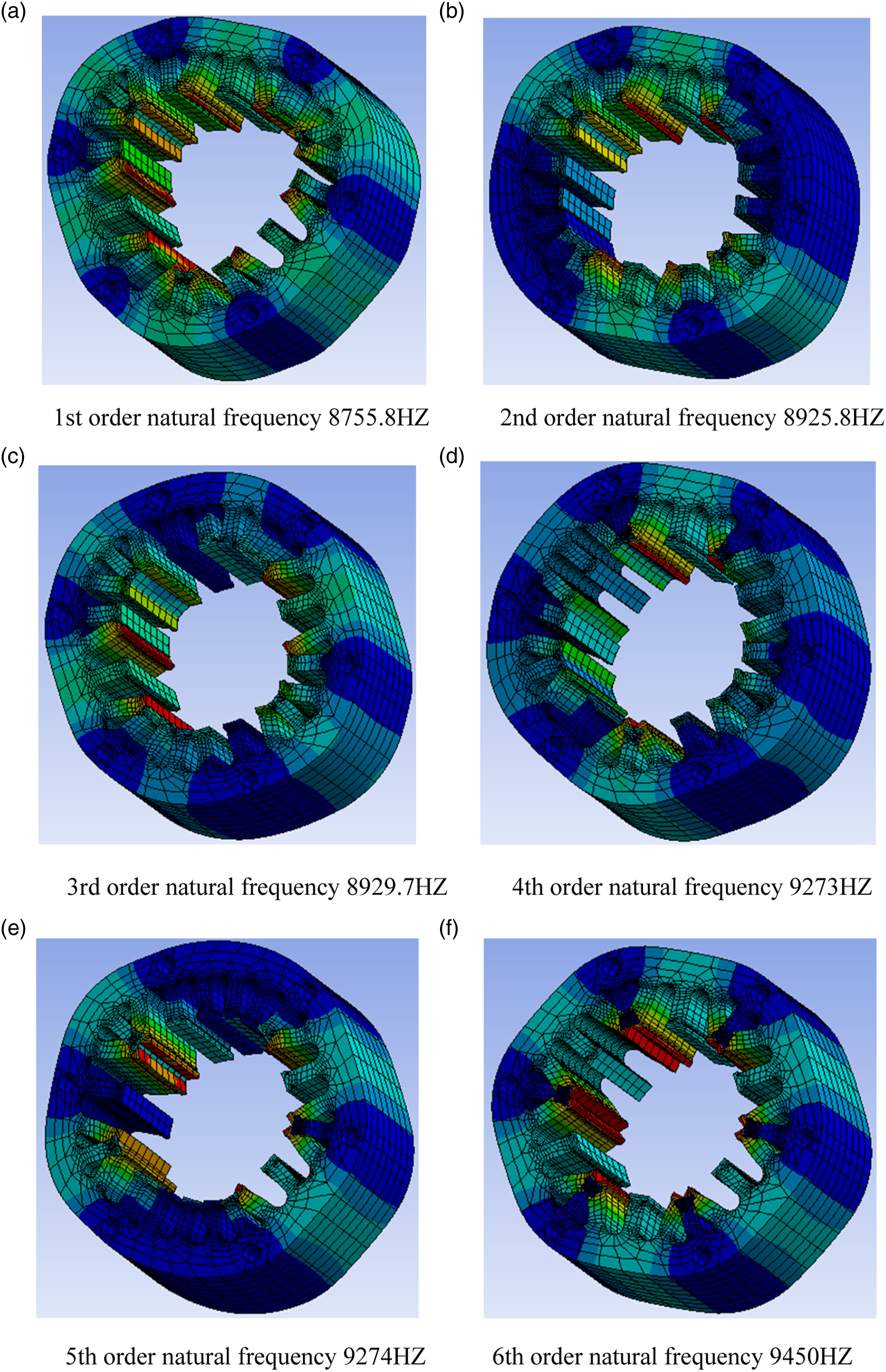
After the modal analysis, the first 6-order natural frequencies of the stator are obtained. Its natural frequency starts from 8755.8HZ; the frequency is higher, indicating that the motor stator has greater rigidity. In view of these dangerous resonance frequency points, the following will analyze whether the radial electromagnetic force will have a greater impact on the motor near the natural frequency point.
Harmonic Response Analysis
In order to observe the vibration state of the motor near the stator natural frequency point, the solution frequency range is set to 0∼10,000HZ through importing the Maxwell model into the workbench and applying the radial electromagnetic force to the stator teeth. The solution result is shown in Figure 9. Harmonic response analysis diagram. (a) Sound pressure distribution under 100HZ. (b) Sound pressure distribution under 800HZ. (c) Sound pressure distribution under 8000HZ. (d) Sound pressure distribution under 9300HZ.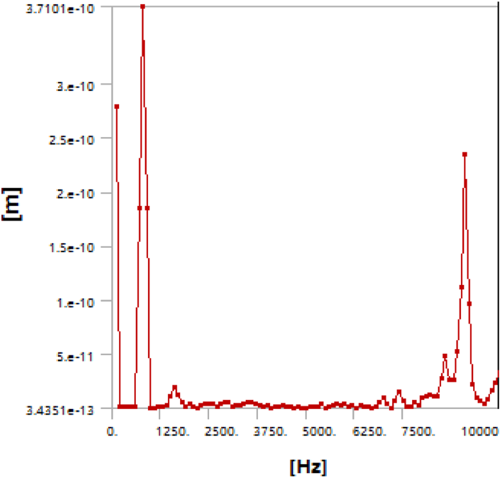
In the figure, the abscissa is the vibration frequency and the ordinate is the vibration amplitude. It can be seen that under the influence of low-order electromagnetic force, the vibration peak value is at 800HZ; when the stator natural frequency range is close, although the high-order harmonics have been attenuated to a small level, the vibration amplitude is affected by resonance. The above trend is still present, and at 9300HZ, the vibration peak value is
Compared with the two peaks, in the high-frequency range, although it is affected by resonance, the resulting vibration peak is still not as large as the low-frequency peak. Therefore, the main source of vibration of the motor is the low-frequency vibration generated by the low-order electromagnetic force. However, its maximum amplitude is only
Noise analysis
In order to observe the noise generated by the motor near the resonance point, the solution range is still set to 0∼10,000HZ by setting the noise solution domain to a 0.8 m cylindrical area around the motor and importing it into the model. Furthermore, for the frequency points with larger vibration amplitude in Figure 9, the noise situation at these frequency points is observed, and the result is shown in Figure 10. Sound pressure distribution diagram at dangerous frequencies.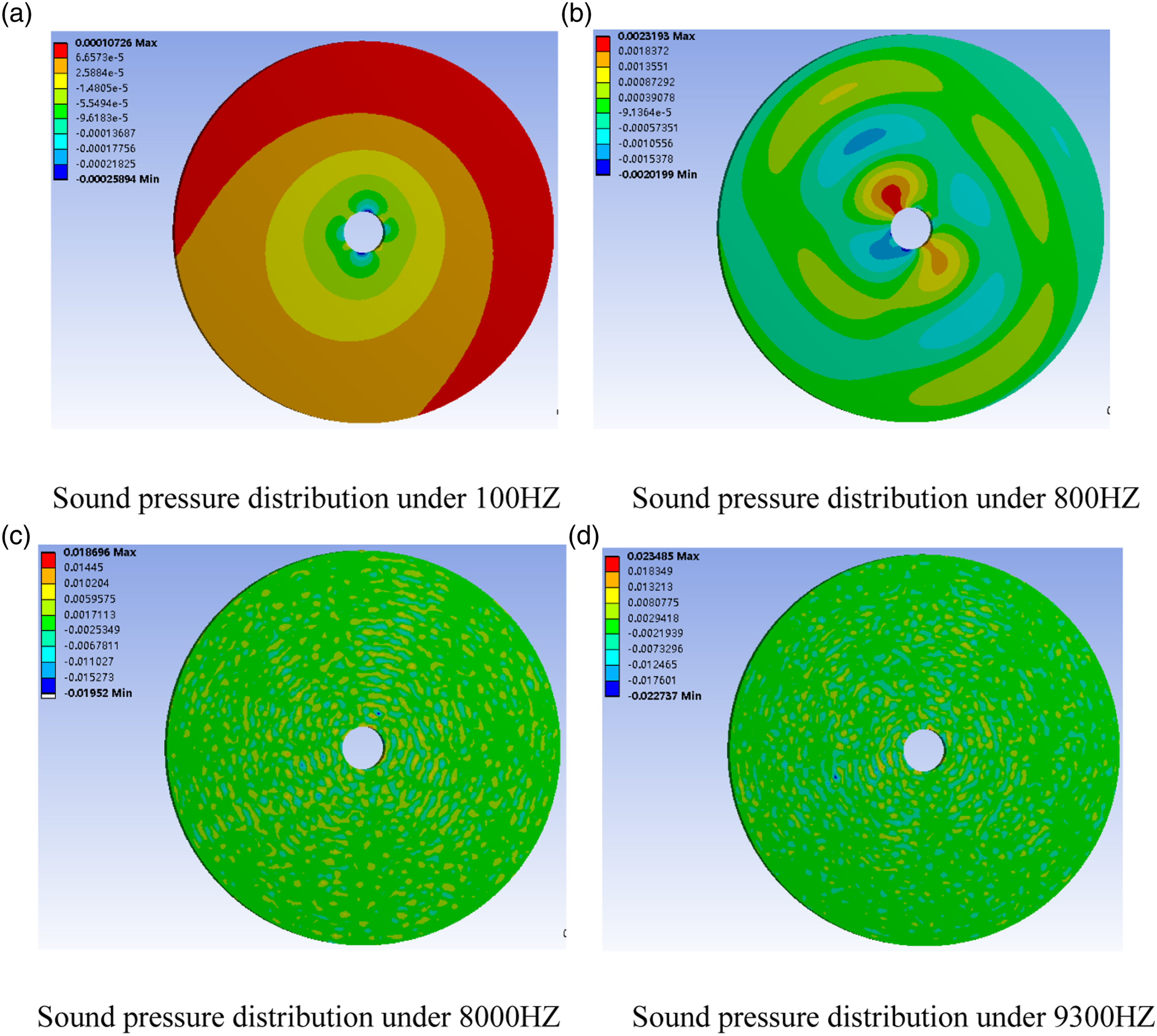
It can be seen from the figure that even at several frequency points where vibration and noise are most likely to be generated, the maximum sound pressure within a range of 0.8 m from the motor is only about 0.02 Pa, indicating that the motor does not produce significant noise.
Conclusion and further work
This paper takes a 22 KW high-speed magnetic suspension rock wool centrifuge as the research object and investigates its vibration and noise. The cause of vibration and noise is analyzed, and the mathematical model of the radial electromagnetic force is derived. Electromagnetic simulation of the motor was carried out based on Maxwell, and the motor design was improved in terms of the simulation results. The optimization scheme was carried out based on Workbench modal analysis, harmonic response analysis, and noise analysis, which verified the rationality and feasibility of the proposed model and approach. The following conclusions are drawn: (1) It is theoretically analyzed that the vibration and noise of the HMS-PMSM are mainly caused by the shrinkage and expansion of the stator core caused by the radial electromagnetic force. According to the deduced formula, the key parameters of the motor vibration and noise, such as the magnetic induction, magnetomotive force, and the number of slots are obtained. (2) The electromagnetic simulation analysis of the HMS-PMSM based on Maxwell shows that the magnitude of the radial force density wave mainly depends on the magnetic induction intensity in the air gap. After the FFT decomposition of the radial force density wave, space harmonics of different orders are superimposed with time harmonics of different orders. The amplitude of the harmonics decays rapidly as the order increases on the trend. (3) By selecting appropriate short-distance windings, the harmonic amplitude of the primary order can be effectively decreased, thereby reducing the vibration and noise of the HMS-PMSM. The optimized scheme can reduce the force density wave amplitude by 22.4%. (4) Based on Workbench, the modal analysis and harmonic response analysis of the HMS-PMSM were carried out. It is concluded that the main influences on the motor vibration and noise are the low-order high-amplitude radial force density harmonics and the high-order harmonics near the resonance frequency point. The amplitude of the high-frequency vibration caused by resonance is less than the amplitude of the low-frequency vibration caused by the low-order electromagnetic force wave. Through the noise analysis, the sound pressure value generated at each dangerous frequency point is reasonable, which verifies the feasibility of the optimization scheme.
In conclusion, we have completed the theoretical analysis of the vibration and noise regarding the high-speed magnetic suspension permanent magnet synchronous motor, but further work on the model accuracy and effectiveness is required through investigating practical application. We will conduct a further physical experiment validation of the vibration and noise on HMS-PMSM through cooperating with the related enterprise.
Footnotes
Acknowledgments
First, our deepest gratitude goes to the anonymous reviewers for their careful work and thoughtful suggestions that have helped improve this paper substantially. Second, we thank Dr Xinlong Wei for his technical assistance.
Declaration of conflicting interests
The author(s) declared no potential conflicts of interest with respect to the research, authorship, and/or publication of this article.
Funding
The author(s) disclosed receipt of the following financial support for the research, authorship, and/or publication of this article: This work was supported by the Natural Science Foundation of the Jiangsu Higher Education Institutions of China (Grant no. 17KJB460018).