
Abstract
This article is concerned with thermal vibration behaviors of the functionally graded material–stepped cylindrical shell coupled with annular plate, including free vibration, transient response, and steady state response. The stepped cylindrical shell is divided into N s segments at locations of thickness and radius variations, which is coupled with N p annular plates. The boundary and coupling conditions are achieved by introducing the artificial virtual spring technology. Under the framework of FSDT, the displacement function of arbitrary shell segment and annular plate is expanded with Chebyshev polynomials and Fourier series for circumferential direction. Compared with results obtained by the finite element method and the references, a series of numerical examples and validations are presented to verify the convergence and accuracy of the current method. The effects of the relevant parameters containing the geometric parameters, boundary conditions, various loadings, and the thermal environment are investigated in detail.
Keywords
Introduction
The cabin structures of high-speed trains, rockets, and submarines are subjected to the extreme environment such as high speed, extreme high and low temperature, high pressure, erosion, dynamic loads, and even attacks. Therefore, ensuring the stability and safety of the structure in the aforementioned extreme conditions is of great importance in practical engineering fields. Functionally graded material (FGM)–stepped cylindrical shell coupled with annular plate combines the advantages of different materials and the advantages of the coupled structure, which has excellent mechanical properties and stable chemical properties. For this reason, the FGM-stepped cylindrical shell coupled with annular plate is widely applied in many engineering fields, especially in some occasions with extreme high speed, high pressure, and temperature. Subsequently, the relevant investigation on vibration of the shell–plate combinations has attracted extensive attention.
Substantial investigations on cylindrical shell and annular plate have been conducted.1–14 Then, some researches have been published on the coupling structure derived from shell and annular plate,15–24 and most of them are about shell–shell or cylindrical shell–rectangular combinations. Based on the above study, there have been researches on vibration of the cylindrical shell coupled with annular plate. Ma 25 presented a unified solution for vibration analysis of cylindrical shell coupled with annular plate. By means of a Fourier–Ritz method, displacements of the cylindrical shell and annular plate can be obtained, regardless of the boundary constraints and continuity conditions. Cheng 26 analyzed the free vibration of a structure coupled by a finite cylindrical shell and a circular plate at one end using the Rayleigh–Ritz method together with the artificial spring technique. Cao 27 took an improved Fourier series method into analysis for vibration of a cylindrical shell–circular plate coupled annular plate–cylindrical shell. The wave-based method was introduced by Xie 28 to observe the free and forced vibration of elastically coupled thin annular plate and cylindrical shell structures. Liu 29 took the wave-based method to investigate the free vibration characteristics of functionally graded cylindrical shell under arbitrary boundary conditions, with consideration of the influences of power law exponents and geometric parameters. Qin 30 investigated free vibrations of rotating thin cylindrical shell with an annular moderately thick plate with Chebyshev–Ritz method. The effects of geometric parameters and boundary conditions and stiffness coupling springs were considered. Zhang 31 presented the free and forced vibration analysis of circular cylindrical double-shell structures under arbitrary boundary conditions.
Efforts have also been made to study the influence of temperature on vibration of FGM structures. Aris 32 and Yang 33 study the nonlinear vibration of FGM-truncated conical shell in thermal environment. Then, Fu 34 investigated FGM conical shell subjected to parametric excitation and nonlinear thermal loading. Li 35 presented a semi-analytical method for free vibration of spiral-stiffened multilayer functionally graded cylindrical shells under the thermal environment. Considering the elastic foundation,36–40 investigated the free vibration of FGM cylindrical shell in the thermal environment. Li 41 presented a general approach for the thermal vibration of FGM porous–stepped cylindrical shell with characteristic orthogonal polynomials. Ninh 42 analyzed the FGM convex–concave shells with electro-thermal-mechanical loads surrounded by the Pasternak foundation. Minh 43 investigated the free vibration of cracked FGM plate with nonlinear varying thickness under thermal environment. Wang 44 analyzed the effects of volume fraction, distribution pattern, geometrical characteristics, and temperature on the buckling behaviors of the functionally graded carbon nanotube–reinforced composite quadrilateral plate with the first order shear deformation theory (FSDT) and Moving Least Squares (MLS) theory. Based on the three-dimensional theory, Yang 45 investigated the thermal response of FG annular plates. With the generalized differential quadrature method, Javani 46 analyzed the large amplitude forced vibration reduced by rapid heating of the surface of the FG annular plate. Lal 47 also employed the generalized differential quadrature method for analysis of free axisymmetric vibrations of functionally graded circular plates, which is under nonlinear temperature variation. Yang and Fang48,49 observed the vibration behaviors of beam and plate under thermal environment. Yang, Zhong, and Tran50–52 also carried out parametric analysis for FGM plate.
From the above analysis, it is seen that the FGM-stepped cylindrical shell coupled with annular plate accounting for temperature has not been attempted. Nevertheless, the FGM-stepped cylindrical shell coupled with annular plate is one of extensively used engineering structures because of its superior mechanical and chemical properties. The main challenge to analyze the vibration of FGM-stepped cylindrical shell coupled with annular plate is the complexity of matching the coupling conditions between the substructures which increases the difficulty of the corresponding theoretical modeling. Furthermore, taking the effects of temperature into account also complicates the theoretical formulation. In addition, most of the aforementioned theses about shell–plate combination are carried out with the finite element method (FEM). FEM is efficient and accurate when subjected to vibration of structures. However, ensuring the accuracy of the high-order vibration with FEM leads much computational cost, and remeshing the FE mesh is essential and cumbersome to deal with the elastic boundary and coupling conditions, and unacceptable growth of calculating costs may be caused. Therefore, a general and accurate approach for analysis of the vibration of the FGM-stepped cylindrical shell coupled with annular plate with temperature is of great significance on both theoretical and practical sides.
The main objective of the current article is to present a general approach for analysis of vibration of the FGM-stepped cylindrical shell and annular plate in the thermal environment. The Chebyshev–Ritz method is employed to analyze the characteristics of free and forced vibration of the coupled annular plate–stepped cylindrical shell in the framework of FSDT. The boundary and coupling conditions are achieved by introducing the artificial virtual spring technology. By setting the cylindrical shell segments to the same thickness and radius and setting the inner diameter of the ring plate to zero, the cylindrical shell of uniform thickness coupled with circular plate can be treated as a special shape of the current model. Compared with those obtained by FEM and the references, a series of numerical examples and validations are presented to verify the convergence and accuracy of the current method. Furthermore, the effects of the relevant parameters containing the geometric parameters, boundary conditions, various loadings, and the thermal environment are investigated in detail.
Theoretical analysis
Establishment of the model
As illustrated in Figure 1, the model for analysis is established in the framework of the first-order shear deformation theory. The stepped functionally graded shell is coupled with a several annular plates through a set of elastic springs. The stepped functionally graded cylindrical shell consists of M sub-shell segments, of which the length and thickness are respectively denoted with L
i
and h
i
(i = 1, 2, …, M). N denotes the number of plates which are connected to shell varying for requirements of investigation. In this analysis, the shell segments and annular plates are separately located at a cylindrical coordinate system (x, The universal model of the functionally graded material–stepped cylindrical shell coupled with annular plate in thermal environment: (a) Geometry model; (b) Coupling springs; and (c) Boundary constraints.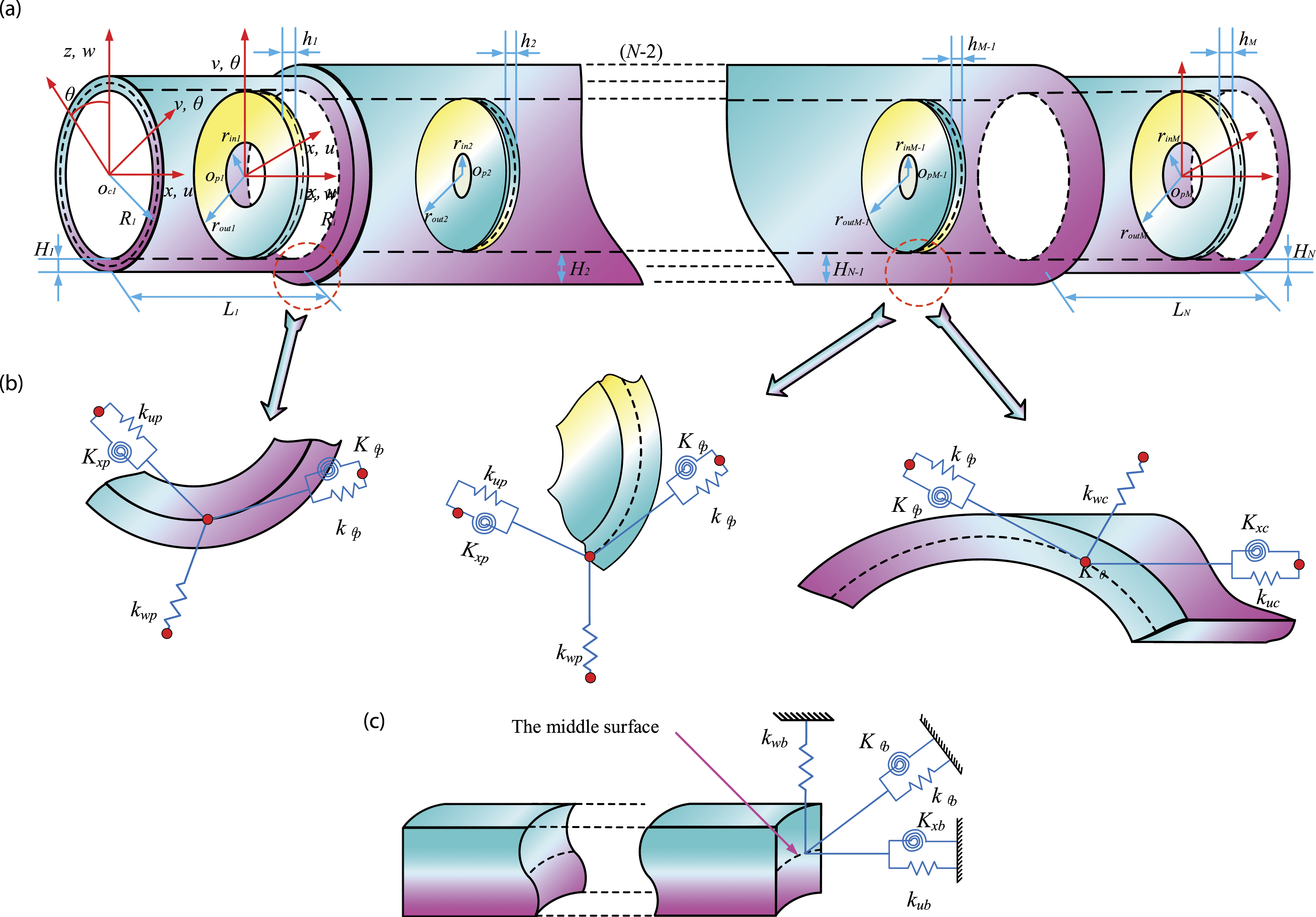
Material properties
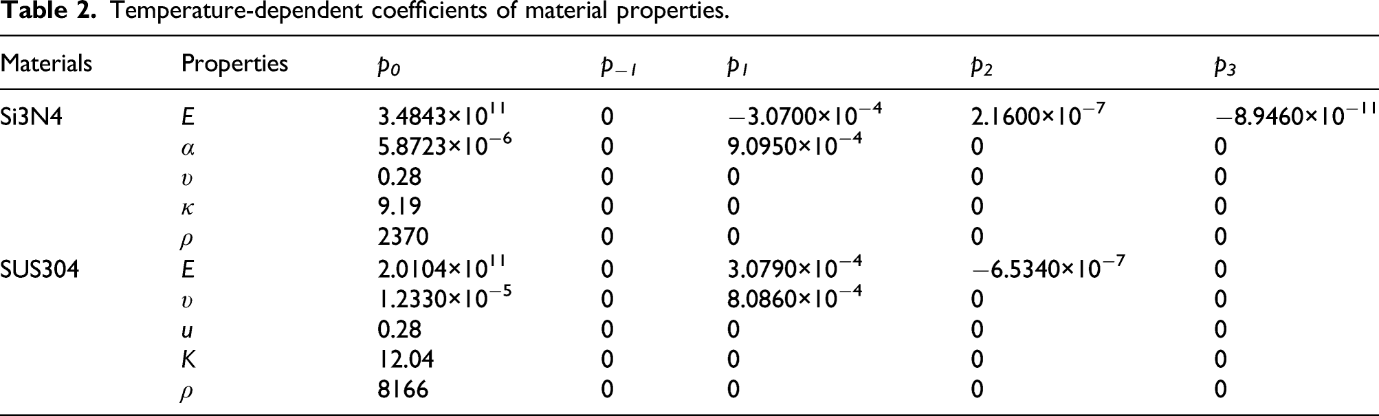
The FGM-stepped cylindrical shell coupled with annular plate is made of a mixture of metal and ceramic materials in this analysis. Since the properties of metal and ceramic materials are sensitive to the environmental temperature, the material properties continuously vary through the thickness from the top surface to the bottom surface of the substructures. For simplicity, the material properties of ceramic and metal are separately denoted by P
c
and P
m
, which can be obtained by the following function of temperature
54


Equations of motion
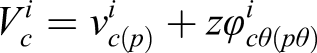
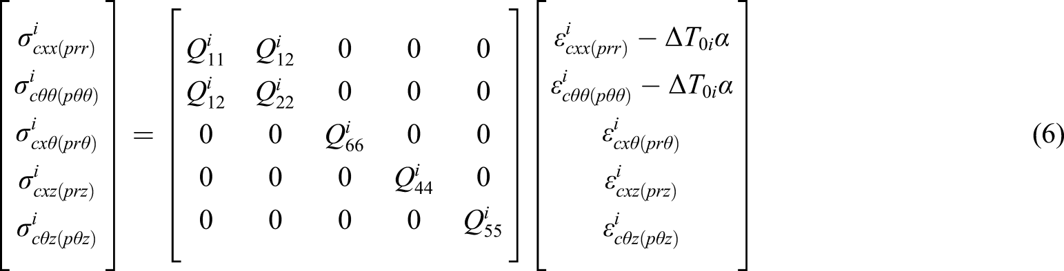
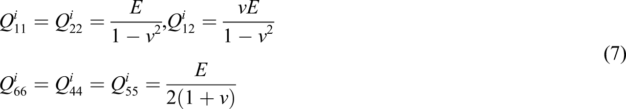
As the above mentioned, the coupled structure herein comprises the stepped cylindrical shell segments and annular plates. In order to obtain the total displacement and strain of the coupled structure, displacements of constituent parts should be presented at the first. For the cylindrical shell segments (annular plate), the displacement components of arbitrary point in x,

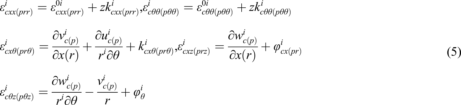
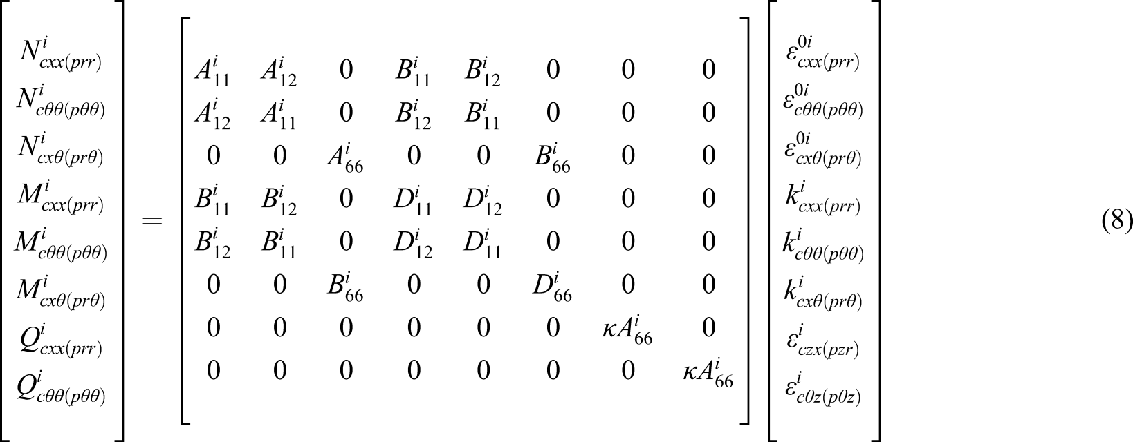
Then, the resultants of stress and moment of the ith cylindrical shell segment and annular plate can be obtained according to equation (8)

Energy equation
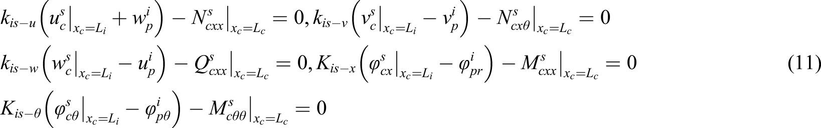
As shown in Figure 1, artificial virtual spring technology is introduced into the coupled model to meet the displacement and physical admissible coordination conditions at coupling locations. Arbitrary coupling conditions can be assumed as

The arbitrary elastic boundary conditions at the coupling locations can be also indicated by
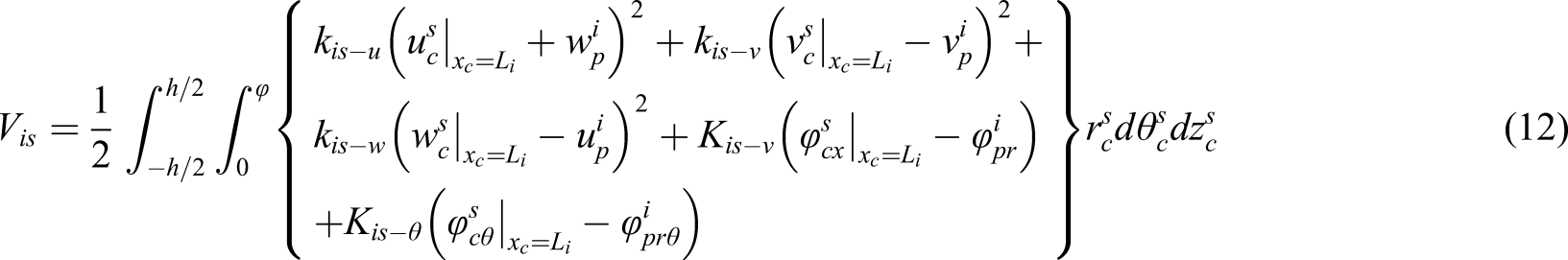
On basis of the forementioned analyses, the strain energy stored by coupled spring associated with cylindrical shell segments and annular plate segments is obtained as
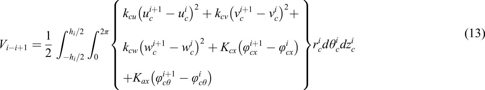
As illustrated in Figure 1 and the mathematically expressions about continuity conditions and boundary conditions, based on the artificial virtual spring technique, the energy stored by springs among the cylindrical shell segments can be indicated by
The kinetic energy and strains energy of components and boundary springs can be written as


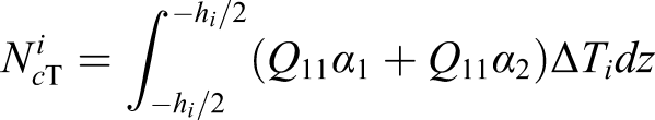
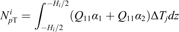
The thermal stress resultant is written as

Rayleih–Ritz energy method is utilized to analyze the characteristics of vibration and transient response of the cylindrical shell coupled with annular plate. The Lagrangian energy function is expressed as


The Chebyshev polynomials of second kind are defined as

The admissible displacement exponents of arbitrary shell segment and annular plate can be expanded by means of Chebyshev polynomials as


Numerical results and discussion
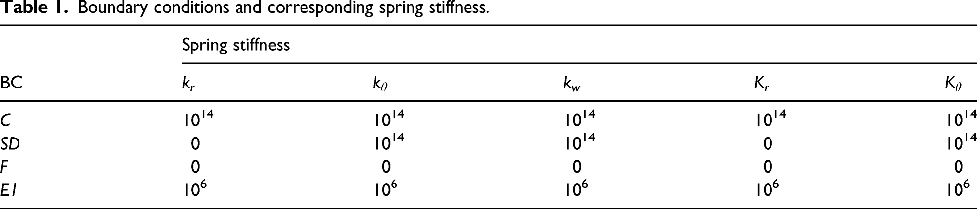
Boundary conditions and corresponding spring stiffness.
Temperature-dependent coefficients of material properties.
Convergence and validation studies
As a foundation of the current research, convergence and validation cases should be conducted at the first. The geometrical parameters and material properties of the stepped cylindrical shell coupled with annular plate are: h
i
= h
p
= 0.1 m. Figure 2 presents the convergence behavior of frequency parameter with respect to the truncated number, the axial halfwave number m is chosen from 1 to 3, and the circumferential wave number n is chosen from 1 to 4. The cylindrical shell is clamped at its two ends (C–C). It is observed from Figure 2 that the current results converge rapidly with the increments of truncated number ml. And furthermore, compared results in case of m
l
= 8 and 10, the frequency parameter is almost stable. Thus, the truncated number m
l
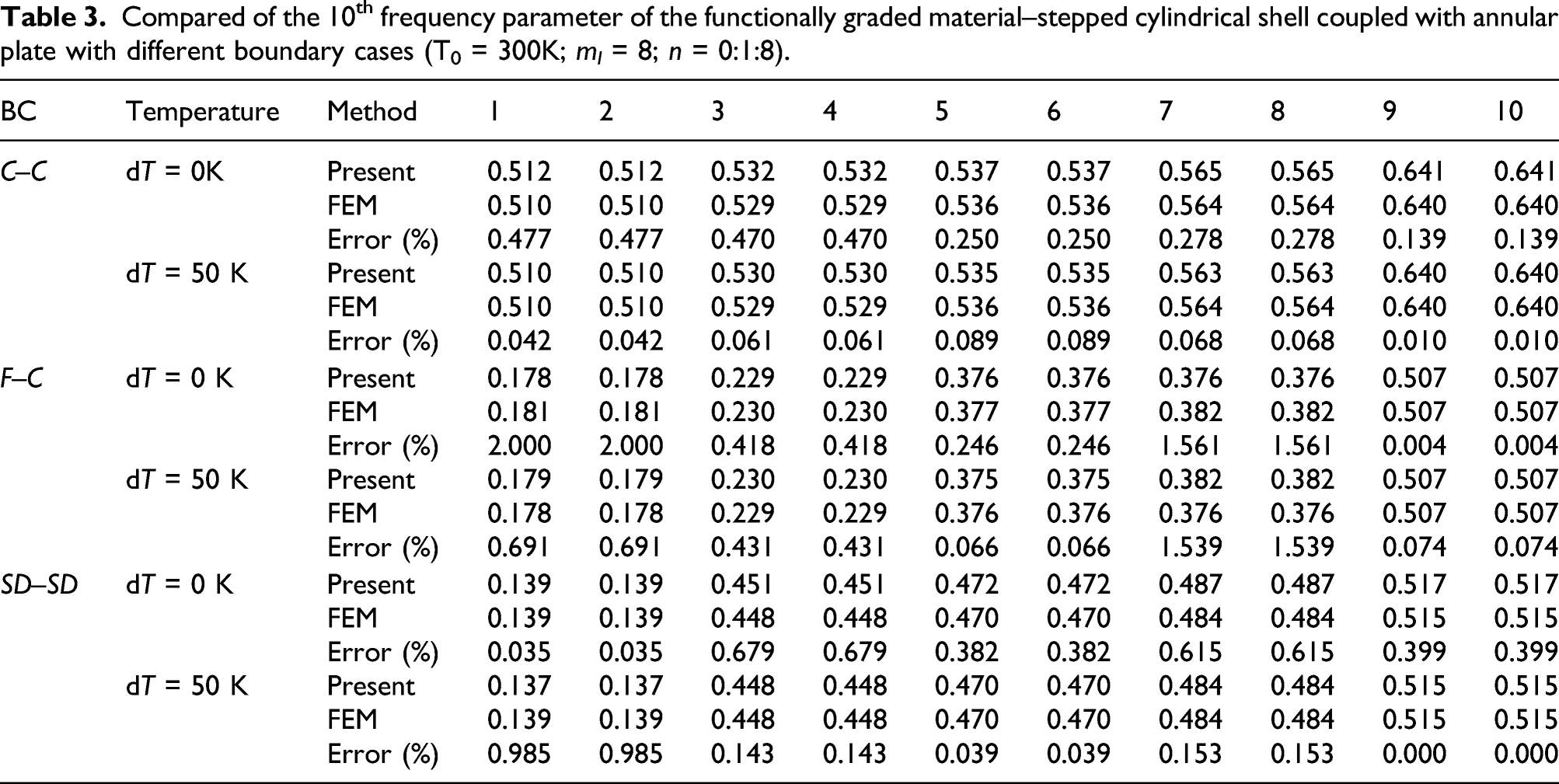
is chosen to be eight in the following calculation. Table 3 shows the comparison of the results with the present method and the finite element method, considering four boundary conditions. The temperature differences are chosen to be 0 K and 50 K. In Table 3, the maximum relative error between results with the present method and FEM reaches rarely 2%, proving the validity of the present method. Convergence behavior of frequency parameter with respect to the truncated number: (a) n = 1; (b) n = 2; (c) n = 3; and (d) n = 4 (C–C; h
i
= h
p
= 0.1). Compared of the 10th frequency parameter of the functionally graded material–stepped cylindrical shell coupled with annular plate with different boundary cases (T0 = 300K; m
l
= 8; n = 0:1:8).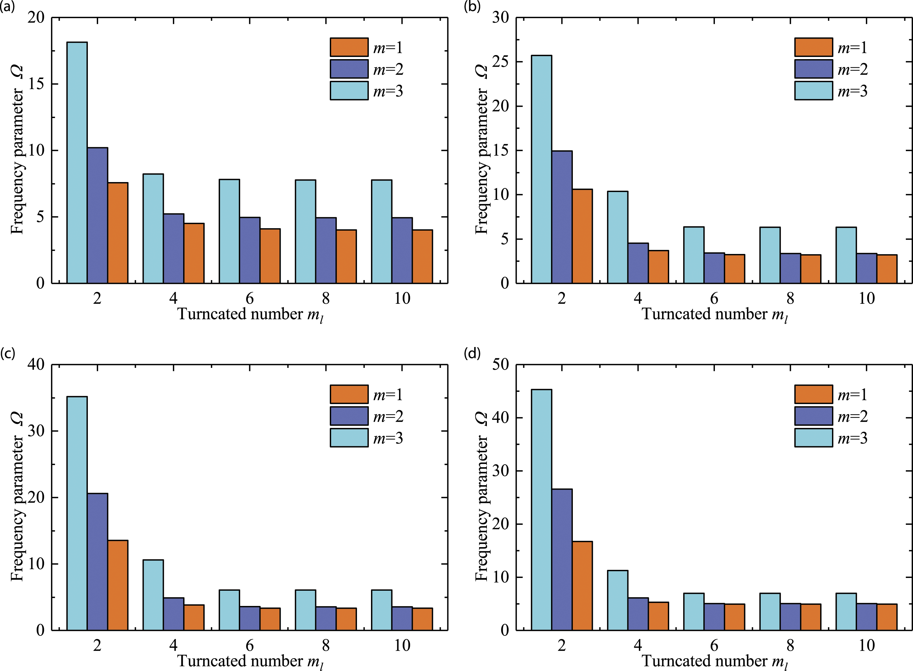
Free vibration analysis
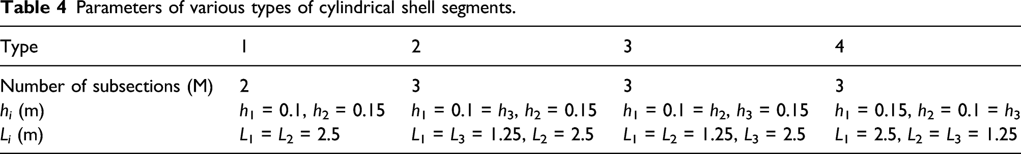
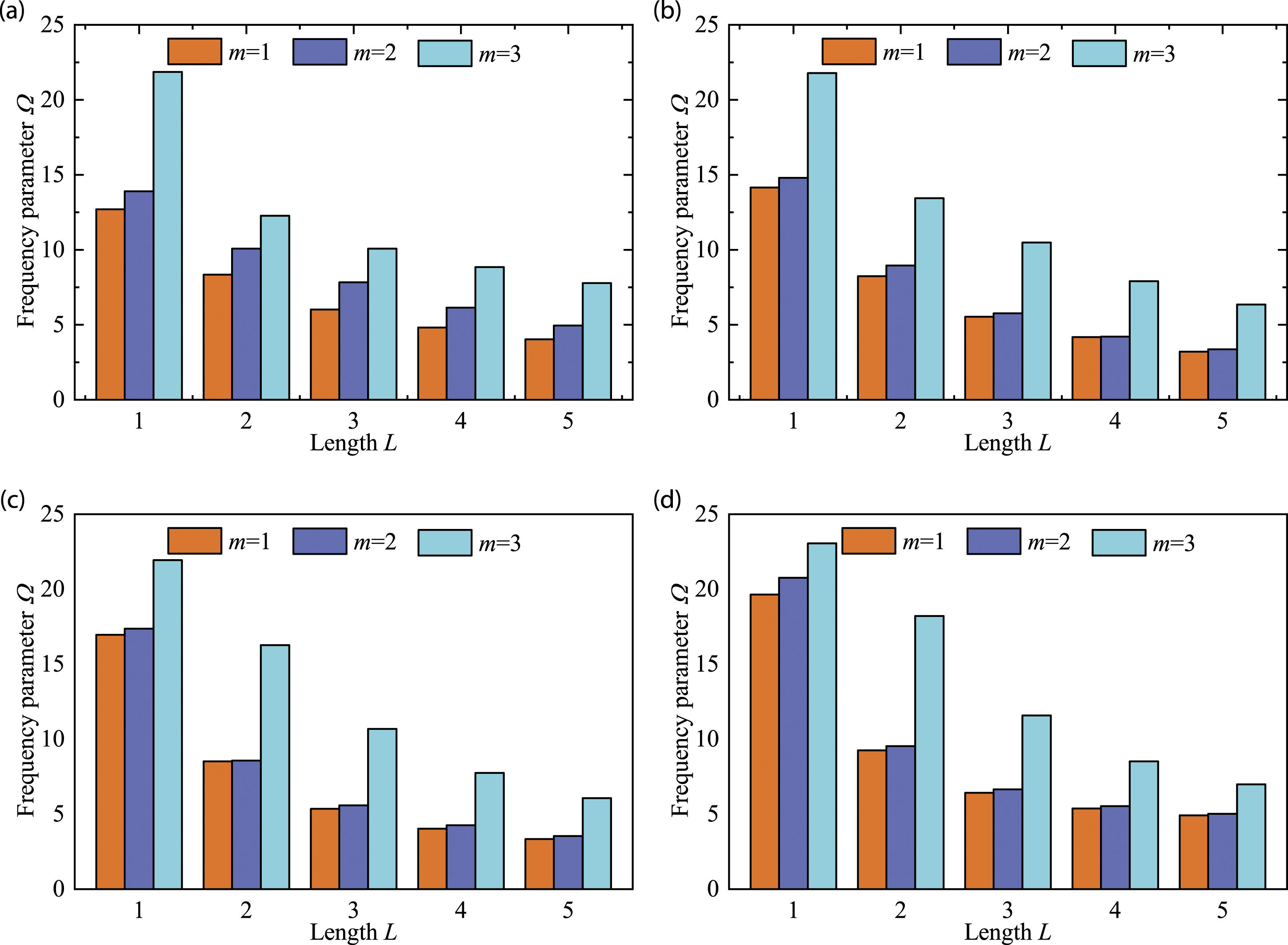
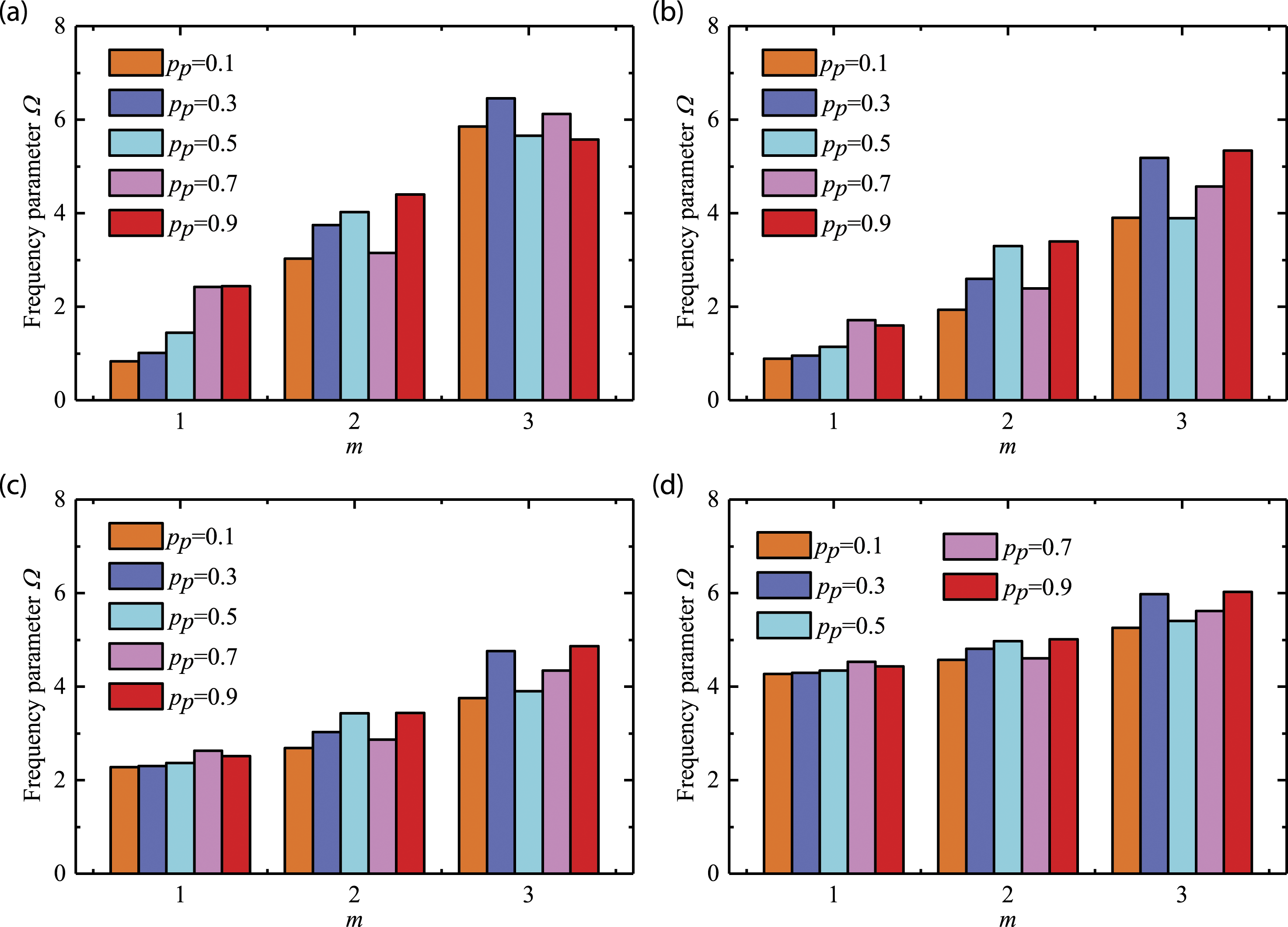
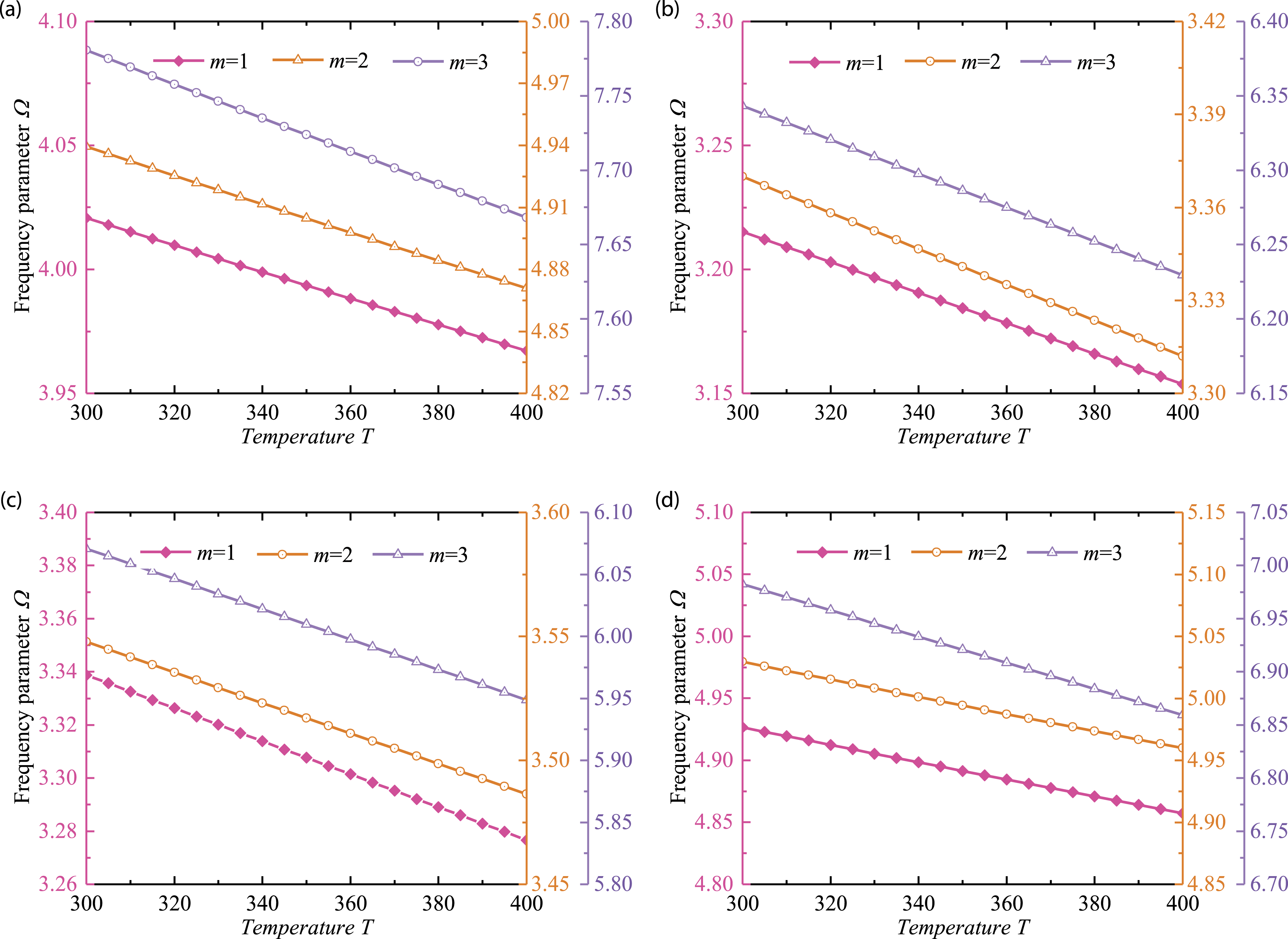
This subsection is concerned with the analysis for free vibration of the FGM-stepped cylindrical shell coupled with annular plate, which is subjected to various boundary conditions, including C–C, C–E1, F–C, and SD–SD boundary conditions. The influence of various types of segments of the cylindrical shell on the frequency parameter of the coupled annular plate–stepped cylindrical shell is exhibited in Figure 3; details about four types of subsections of the cylindrical shell are shown in Table 4. It is noted that in order to facilitate comparison, the total length of the shell segments of the same thickness is chosen 2.5 m. Frequency parameter shown in Figure 3 increases as the number of the circumferential wave number n is increased and as well as the axial halfwave number m. From Figure 3, we can see that the various types of shell segments make effects on frequency parameter of the coupled system. For one thing, frequency of Type 3 is lower than Type 1 when the circumferential number n is below 4, based on the same distribution of the shell segments with thickness of 0.15 and 0.1. This suggests that more shell segments benefit the free vibration of the coupled annular plate–stepped cylindrical shell in term of low frequency. For another, shell segments of Type 4 provide the minimum frequency parameter, indicating that different shell segments distributions have an effect on the frequency of structural free vibration. Figure 4 presents the tendency of frequency parameter of the coupled annular plate–stepped cylindrical shell as the length of cylindrical shell varies from 1 m to 5 m, which is clamped at the ends. Apparently, the frequency parameter of the coupled annular plate–stepped cylindrical shell decreases with increasing the length L of the cylindrical shell. The relation between the frequency parameter of the FGM-stepped cylindrical shell coupled with annular plate and the relative position p
p
of the annular plate is revealed in Figure 5. For the sake of diversity of numerical data, the boundary condition is chosen as C–E1. From Figure 5, it can be concluded that the frequency parameter is sensitive to the relative position of the annular plate. On the one hand, except for n = 1 shown in Figure 5(a), when m is the same, the frequency parameter changes with the relative position in the same law, and as n increases, the influence of the relative position becomes smaller. On the other hand, apart from m = 3 and n = 1 at the same time, setting the relative position p
p
as 0.1 can provide lower frequency parameter of the FGM-stepped cylindrical shell coupled with annular plate regardless of high frequency or low frequency. Figure 6 exhibits the frequency parameter of the FGM-stepped cylindrical shell coupled with annular plate with respect to temperature. The boundary condition is chosen as C–C, thicknesses of cylindrical shell and annular plate are both chosen to be 0.1. It is observed from Figure 6 that the frequency parameter of the FGM-stepped cylindrical shell coupled with annular plate decreases linearly with increasing temperature. Frequency parameter with respect to different types of subsections: (a) C–C; (b) C–E1; (c) F–C; and (d) SD–SD. Parameters of various types of cylindrical shell segments. Frequency parameter with respect to length of shell: (a) n = 1; (b) n = 2; (c) n = 3; and (d) n = 4 (C–C). Frequency parameter with respect to relative position of circular plate (a) n = 1; (b) n = 2; (c) n = 3; and (d) n = 4 (C–E1). Frequency parameter with respect to temperature (a) n = 1; (b) n = 2; (c) n = 3; and (d) n = 4 (C–C; p
p
= 0.5; L = 5; h
i
= 0.1; h
p
= 0.1).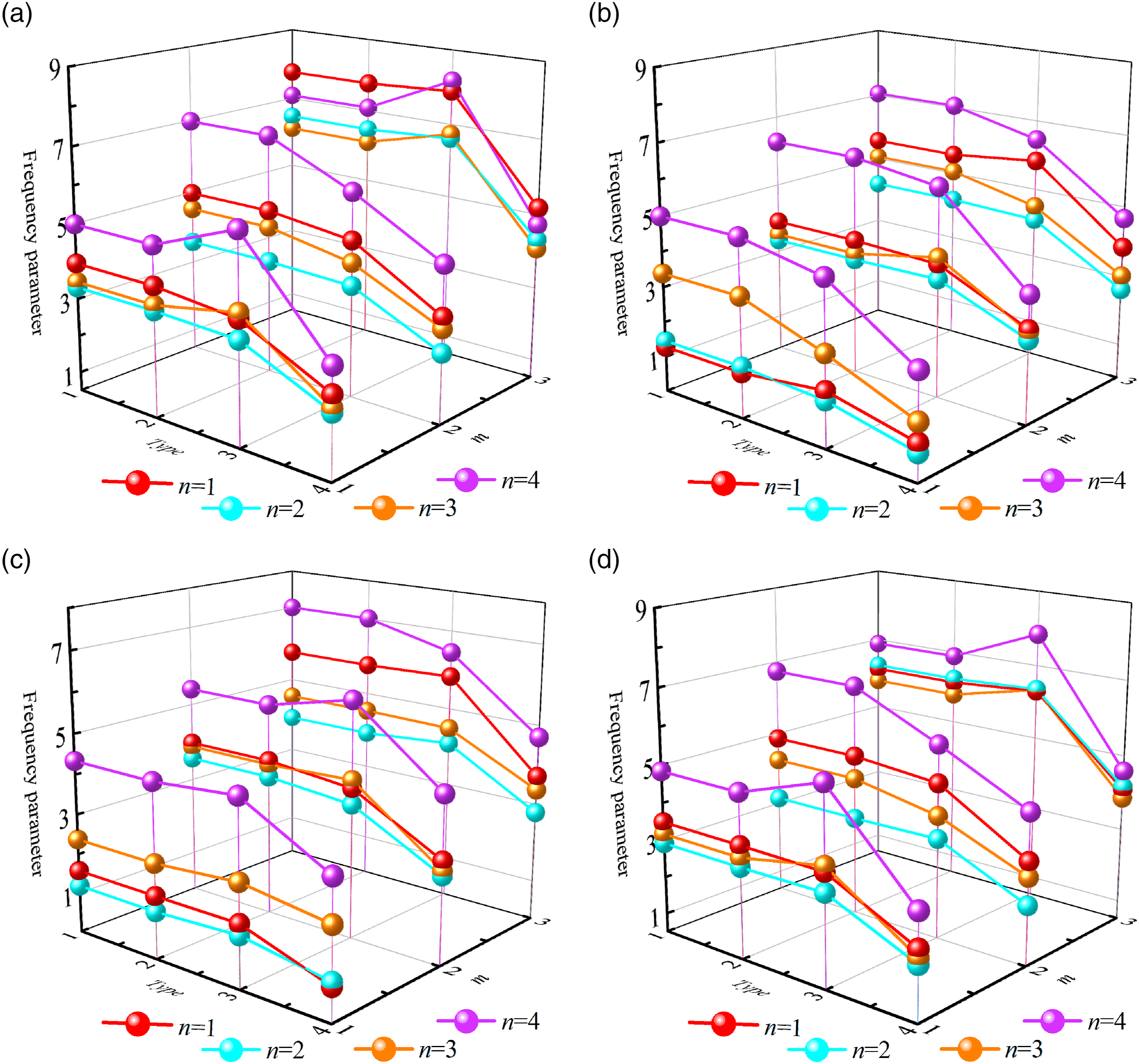
Transient response analysis
In this subsection, numerical examples are selected to illustrate the contribution of geometric parameters and temperature of the FGM-stepped cylindrical shell coupled with annular plate. To begin with, the validation case is presented to confirm the correctness of the current method. Figure 7 presents four types of loading employed in this article: (a) Rectangular pulse; (b) Triangular pulse; (c) Half-sine pulse; (d) Exponential pulse, which are expressed in detail by Ref. 57 As is shown in Figure 8, comparison of transient response of the FGM-stepped cylindrical shell coupled with annular plate with the present method and the finite element method (FEM) is exhibited. Consider the four types of point excitation loading, the boundary constraints are C–C, time for loading (t
l
) is 0.01 s; time for analysis (t0) is 0.02 s; the positions of loading p
l
and measure p
m
point are severally chosen to be (3, 0) and (2, 0) in the x-θ coordinate system, temperature is chosen to be 300 K. It is visibly seen that results obtained with FEM and the present method share excellent agreement, validating the correctness of the present method employed in this article. The sketch of load time domain curve: (a) Rectangular pulse; (b) Triangular pulse; (c) Half-sine pulse; and (d) Exponential pulse. Comparison of transient response of the functionally graded material–stepped cylindrical shell coupled with annular plate (a) rectangular; (b) triangular; (c) half-sine; and (d)exponential (C–C, p
l
= (3, 0); p
m
= (2, 0)).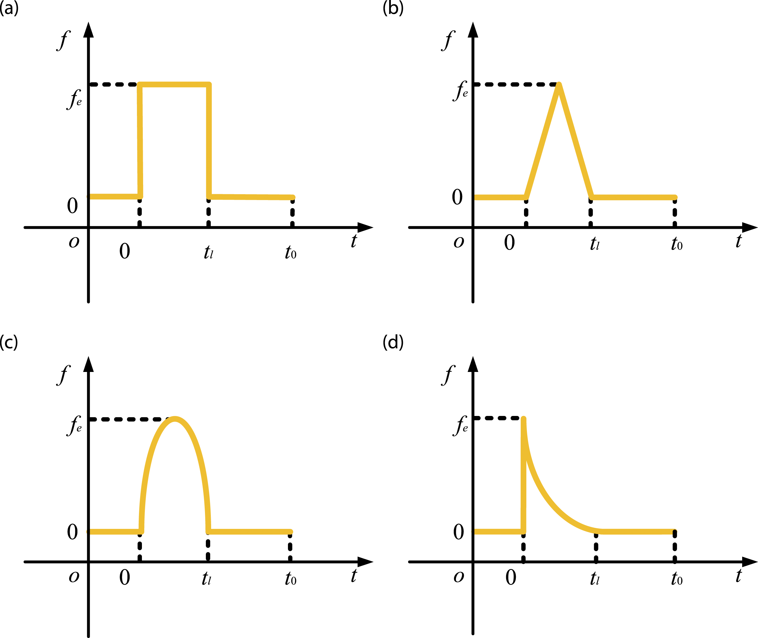
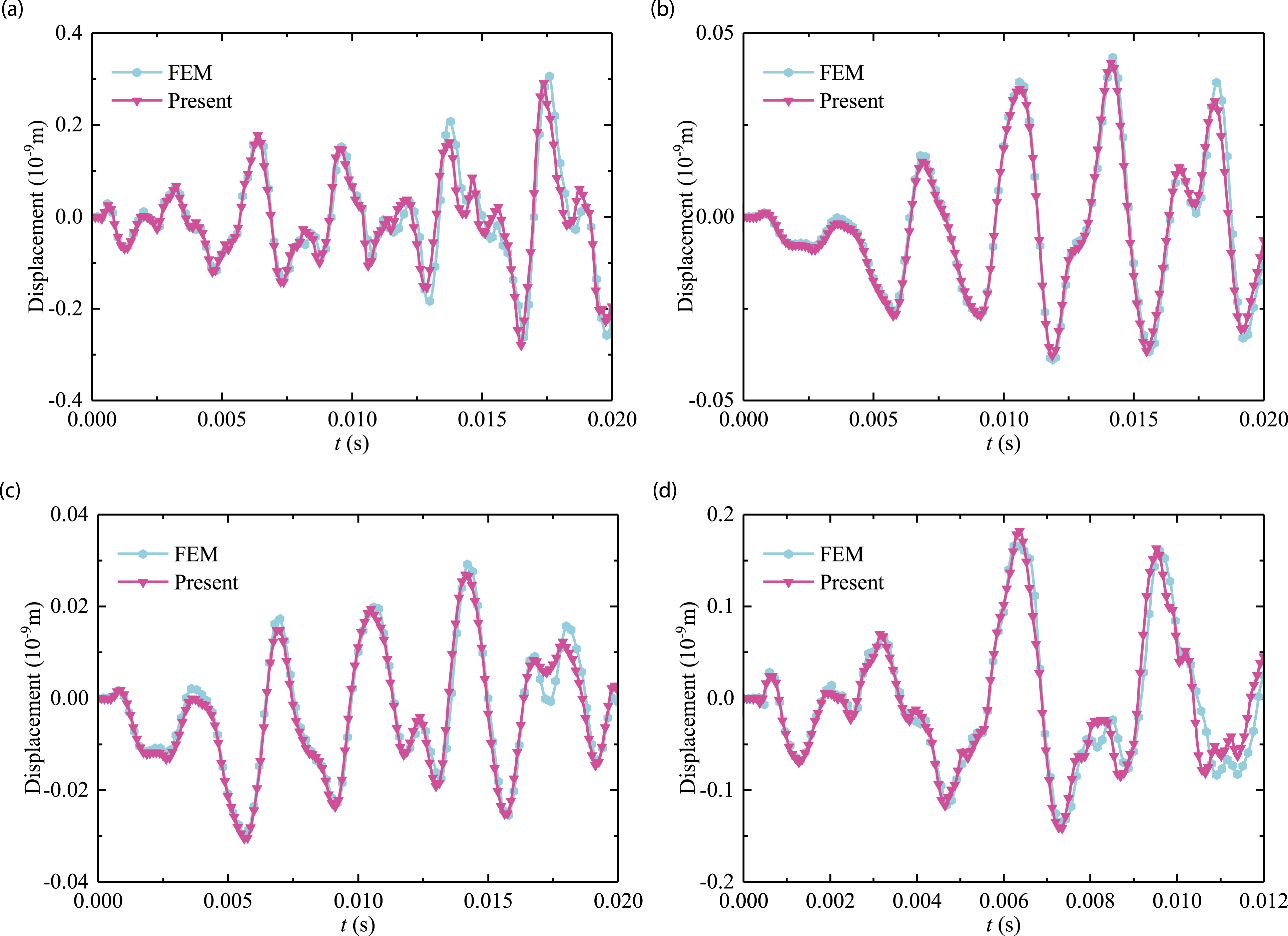
Figure 9 shows the contributions of various types of loading to acceleration of transient response of the FGM-stepped cylindrical shell coupled with annular plate. The boundary condition, time for loading and analysis are chosen from Figure 8; position of loading is (2, 0) in the x-θ coordinate system, while the position of measure point is selected as (1, 0); temperature is 300 K. From Figure 9, the transient response of the FGM-stepped cylindrical shell coupled with annular plate varies evidently owe to different excitations. In Figure 10, four types of cylindrical shell segments are taken into account to study the effect of the number and distributions of segments on the transient response. The boundary conditions are chosen as C–C and SD–SD, the positions of loading p
l
and measure p
m
point, temperature, time for loading and analysis are same as Figure 9. It is visibly seen from Figure 10 that the displacement with types 1 and 3 varies more intensely as time varies from 0 to 0.02 s, and curves of types1 and 3 are very close. Besides, the curves of displacement gradually become gentle when time is over 0.01 s. In other words, the transient response is hardly related to the number of cylindrical shell segments, while the distribution of shell segments makes more influence. With purpose that analyzes the effect caused by the inner diameter of the annular plate on the transient response of the FGM-stepped cylindrical shell coupled with annular plate, Figure 11 illustrates the changes of transient response considering the inner diameter of annular plate. The boundary conditions are chosen as F–C and SD–SD; the type of loading is triangular; p
l
= (2, 0); p
m
= (1, 0); temperature is 300 k; the inner diameter of annular plate is r
p
selected to be 0, 0.1, 0.2, 0.3. It is noted that the annular plate would be circular plate as the inner diameter is selected to be 0. As seen from Figure 11, the trend of four curves with respect to time is similar, and the most change of displacement occurs as the r
p
is 0, curves with r
p
of 0.1, 0.2, and 0.3 are very close, though the displacement provided by r
p
of 0.3 is minimum. In a word, inner diameter makes little difference on transient response of the FGM-stepped cylindrical shell coupled with annular plate as the r
p
is not 0 and range in a certain extent. Transient response of the functionally graded material–stepped cylindrical shell coupled with annular plate with respect to various loadings (C–C, p
l
= (2, 0); p
m
= (1, 0); t
l
= 0.01; t0 = 0.02). Transient response of the functionally graded material–stepped cylindrical shell coupled with annular plate with respect to four types of cylindrical shell segments: (a) C–C; and (b) SD–SD. (p
l
= (2, 0); p
m
= (1, 0); t
l
= 0.01; t0 = 0.02). Transient response of the functionally graded material–stepped cylindrical shell coupled with annular plate with respect to r
p
: (a) F–C; and (b) SD−SD (triangular, p
l
= (2, 0); p
m
= (1, 0); t
l
= 0.01; t0 = 0.02).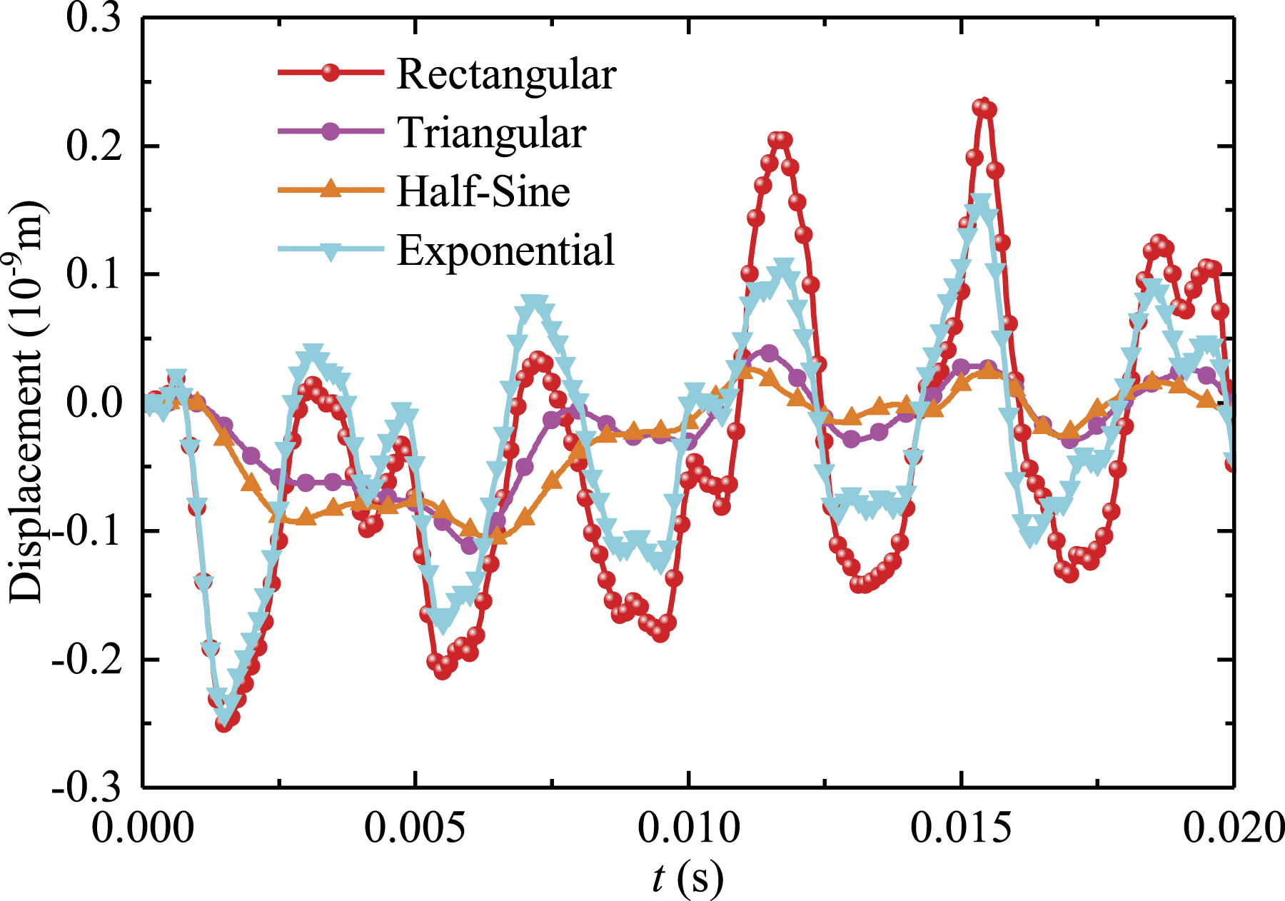
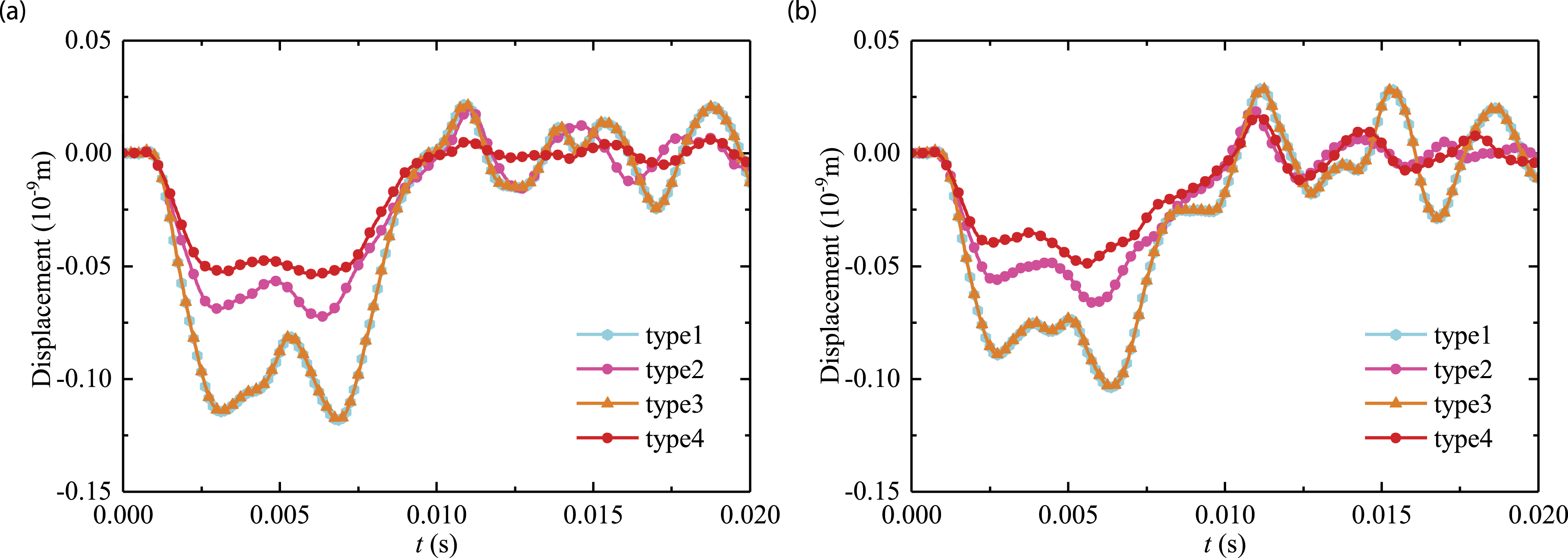
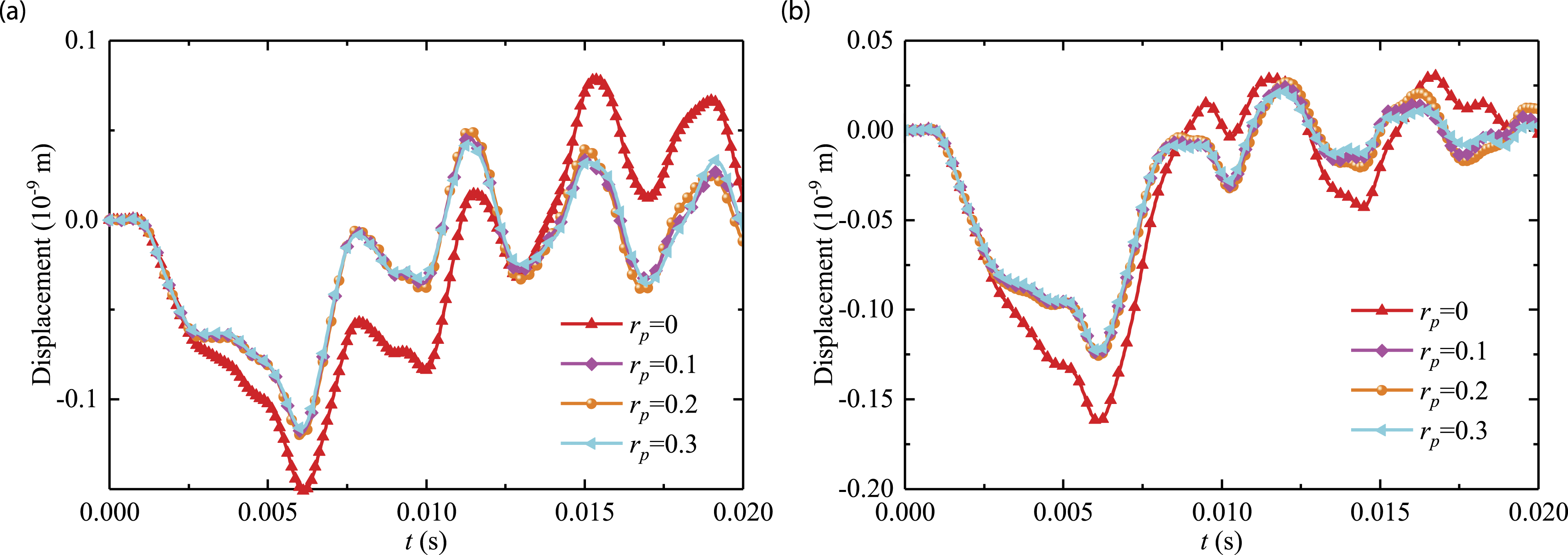
Figure 12 shows the transient response of the FGM-stepped cylindrical shell coupled with annular plate with respect to temperature. The boundary conditions are C–C and SD–SD; p
l
, p
m
, t
l
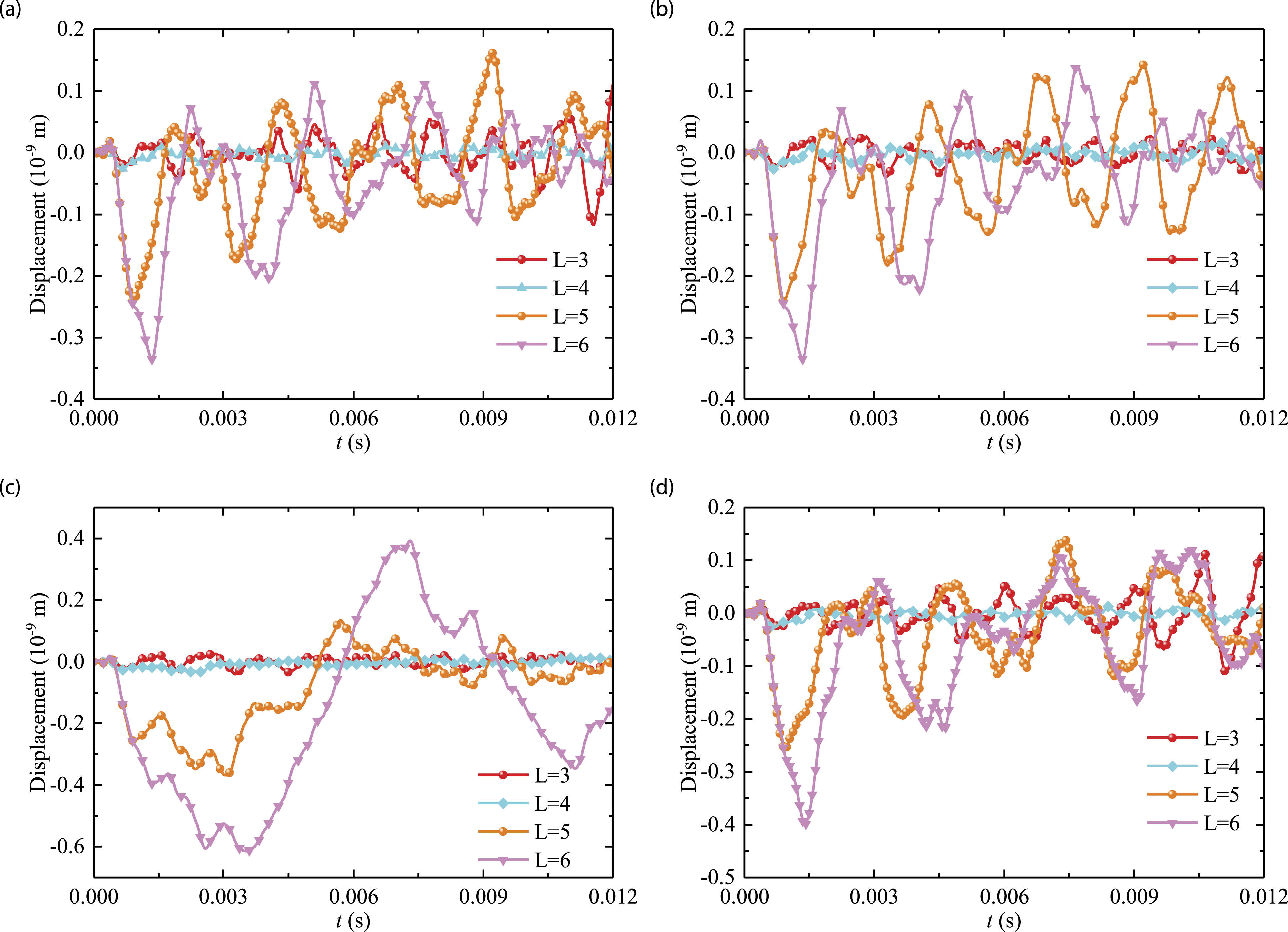
, and t0 are chosen from Figure 11; loading is rectangular. It is seen from Figure 12 that the differences of transient responses with T = 300 K, 340 K, and 400 k are small and the displacement under T = 400 K is the lowest. This suggests that temperature does not work much for transient response of the FGM-stepped cylindrical shell coupled with annular plate. For the completeness, the influence caused by the length L of cylindrical shell is revealed in Figure 13. Various boundary conditions are considered, for instance, C–C, F–C, SD–SD, C–E1; the loading is exponential for sake of diversity of numerical example; p
l
, p
m
, and temperature are chosen from Figure 11; t
l
and t0 are 0.01 s and 0.012 s. The results show that the longer cylindrical shell leads to more visible displacement of the FGM-stepped cylindrical shell coupled with annular plate and does harm to the FGM-stepped cylindrical shell coupled with annular plate. Transient response of the functionally graded material–stepped cylindrical shell coupled with annular plate with respect to the temperature: (a) C–C; and (b) SD–SD (p
l
= (2, 0); p
m
= (1, 0); t
l
= 0.01; t0 = 0.02; rectangular). Transient response of the functionally graded material–stepped cylindrical shell coupled with annular plate with respect to the length of shell: (a) C–C; (b) F–C; (c) SD–SD and (d) C–E1 (exponential; p
l
= (2, 0); p
m
= (1, 0); t
l
= 0.01; t0 = 0.012).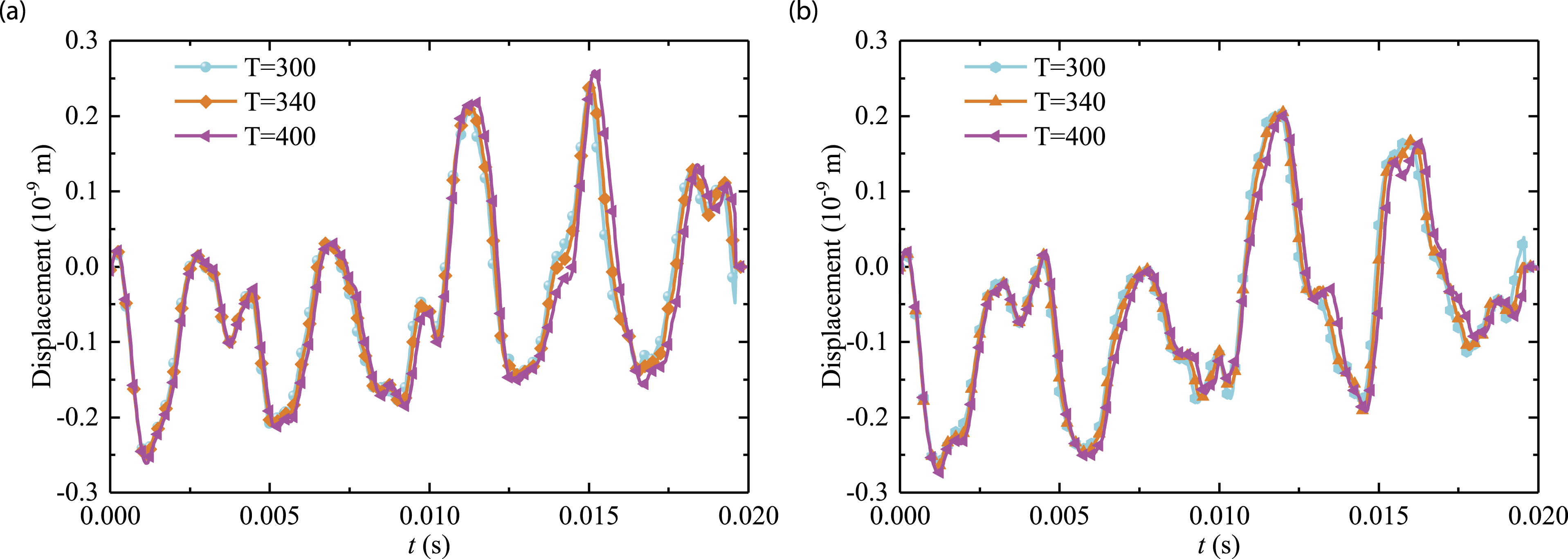
Steady state response analysis
Steady state response of the FGM-stepped cylindrical shell coupled with annular plate is analyzed in this subsection. It is worth noting that the validation case should be conducted as the basis of the following work. Figure 14 presents the comparison of steady state response of the FGM-stepped cylindrical shell coupled with annular plate with the present method. In order to avoid occasionality of calculation, measure point position is chosen as (2, 0) and (1, 0) in the x-θ coordinate system; loading position is (3, 0); thicknesses of cylindrical shell and annular plate are both 0.1 m; the boundary condition is C–C. As is seen from Figure 14, the results with the present method and FEM share good agreement. In other words, the present method is suitable for the steady state response calculation of the FGM-stepped cylindrical shell coupled with annular plate owe to its correctness. Comparison of steady state response of the functionally graded material–stepped cylindrical shell coupled with annular plate: (a) measure point A (2, 0); and (b) measure point B (1, 0) (C–C; h
i
= 0.1, h
p
= 0.1, p
p
= 0.5; p
l
= (3, 0)).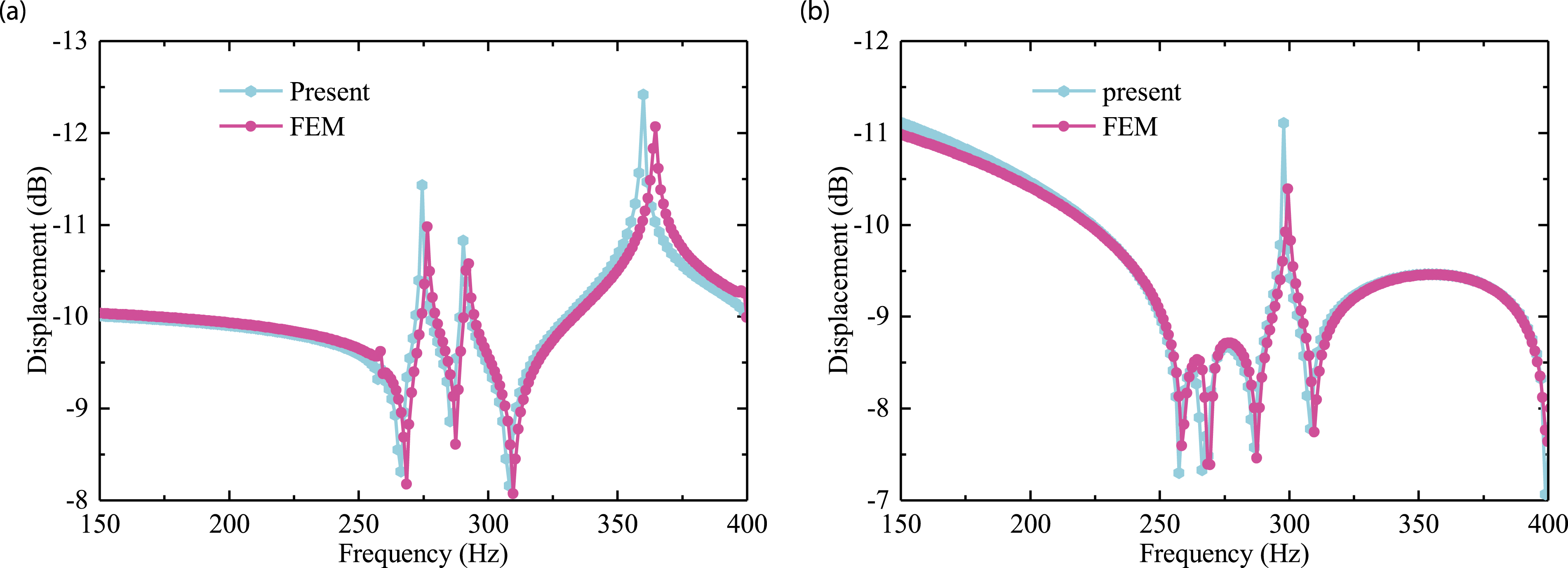
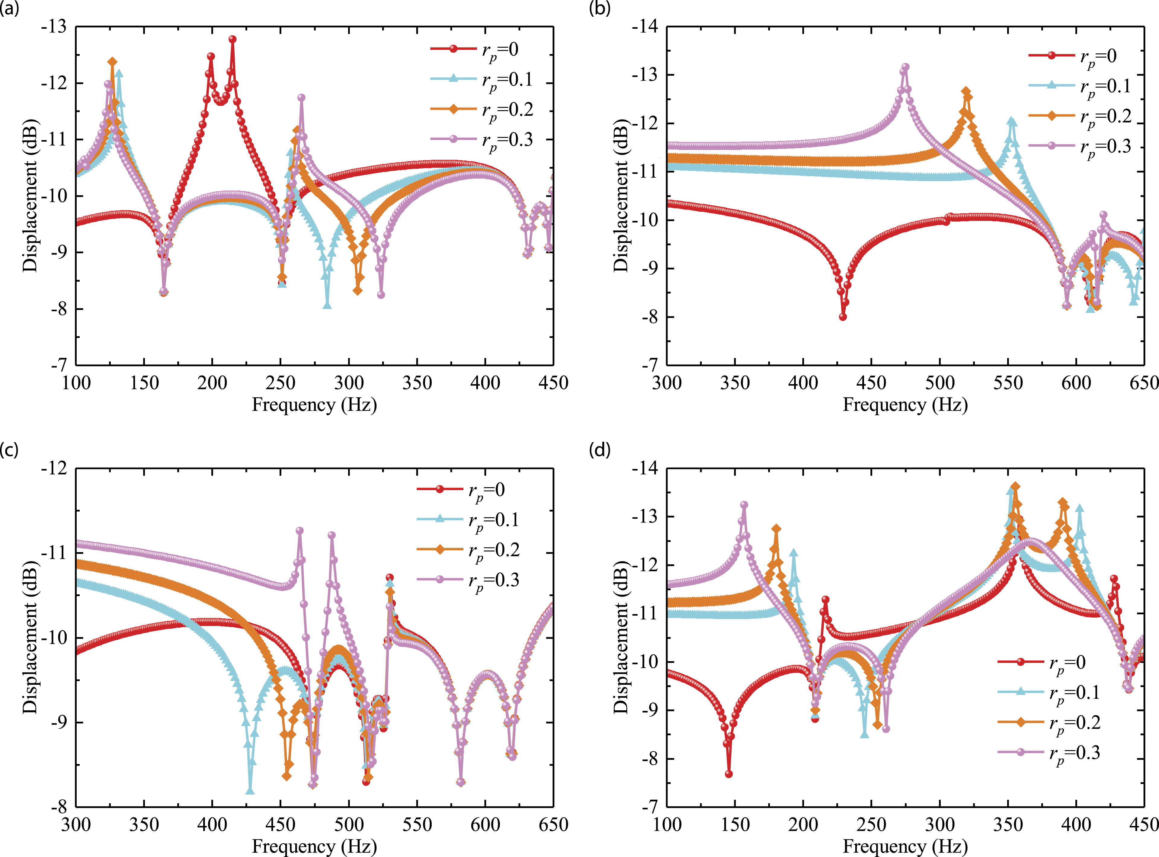
Next, effects of parameters of the geometry, relative position of the annular plate, and temperature are analyzed. Figure 15 shows the steady state response of the FGM-stepped cylindrical shell coupled with annular plate with respect to various length L of cylindrical shell. C–C, F–C, SD–SD, and F–E1 boundary conditions are employed to ensure the comprehensiveness of the numerical solutions; thicknesses of the annular plate and cylindrical shell are both 0.1 m. Positions of loading and measure point are (3, 0) and (2, 0) in the x-θ coordinate system. From Figure 15, it can be found that displacement is sensitive to the length L of the cylindrical shell. As length L of cylindrical shell increases, peaks of displacement are more concentrated in the frequency region from 300 Hz to 650 Hz. As depicted in Figure 16, the steady state response of the FGM-stepped cylindrical shell coupled with annular plate of uniform thickness with respect to the inner diameter r
p
of annular plate is revealed. Boundary conditions and geometric parameters are same as Figure 15. On the one hand, it is visible that the peaks of displacement shift to low frequency region with increment of r
p
. On the other hand, the number of peaks of displacement in the frequency region from 300–650 Hz does not change as the inner diameter r
p
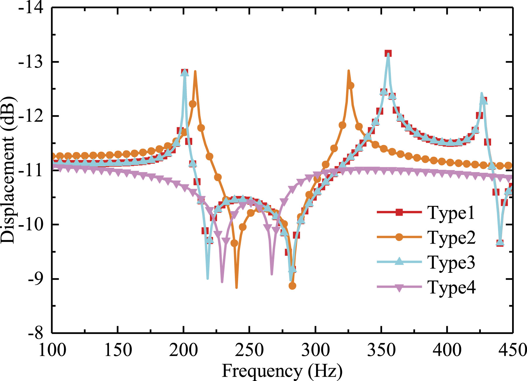
increases. Figure 17 shows the influence of different types of stepped cylindrical shell segments on steady state response of the FGM-stepped cylindrical shell coupled with annular plate. The positions of loading and measure point are same as Figure 15; F–C boundary condition is selected. It is visible curves of Type 1 and Type 3 almost coincide because the difference between Types 1 and 3 is merely number of shell segments. In addition, it is found that displacements of Types 1 and 3 are lower than those of Types 2 and 4, but the number of peaks reverses. In a word, shell segments number plays little role in steady state response of the FGM-stepped cylindrical shell coupled with annular plate, while distribution of shell segments affects. This is in harmony with discussion about transient response. Steady state response of the functionally graded material–stepped cylindrical shell coupled with annular plate with respect to length of shell: (a) C–C; (b) F–C; (c) SD–SD; and (d) F–E1 (h
i
= 0.1, h
p
= 0.1; p
l
= (3, 0); p
m
= (2, 0)). Steady state response of the functionally graded material–stepped cylindrical shell coupled with annular plate with respect to inner diameter of the circular plate: (a) F–E1; (b) C–C; (c) SD–SD; and (d) F–C (h
p
= h
i
= 0.1). Steady state response of the functionally graded material–stepped cylindrical shell coupled with annular plate with respect to various types of cylindrical shell segments: F–C (h
p
= 0.1; p
l
= (3, 0); p
m
= (2, 0)).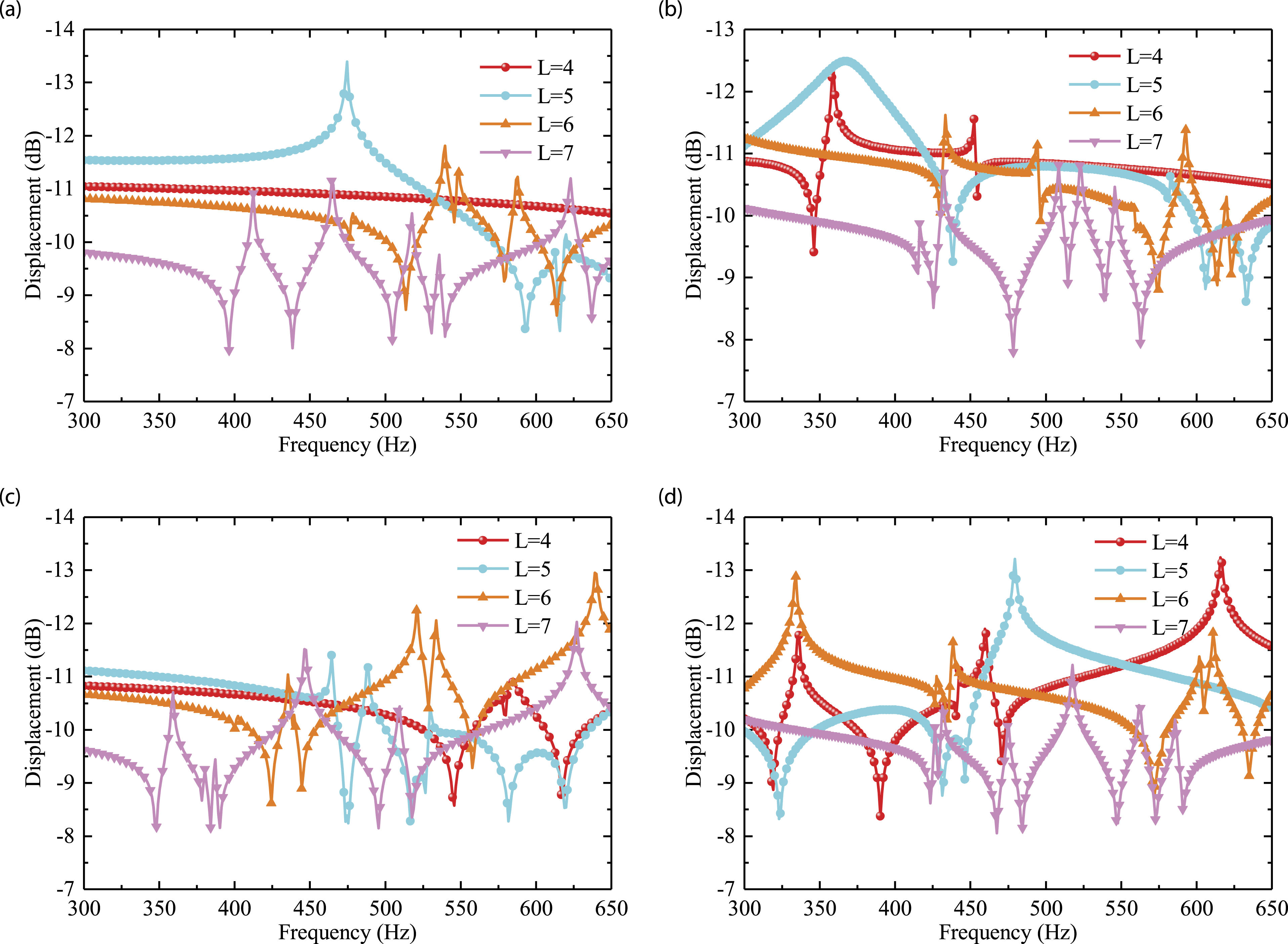
Results considering the relative position of annular plate (p
p
) are exhibited in Figure 18. Different relative positions are taken into calculation to evaluate the contribution to steady state response of the FGM-stepped cylindrical shell coupled with annular plate of uniform thickness. Boundary conditions, thicknesses of cylindrical shell, and circular plate are chosen from Figure 15. Comparing the curves with each other in Figure 18(a) and (c), it can be concluded that curves of symmetrical position of annular plate overlap. The reason is that the constraints at the ends of cylindrical shell are uniform as C–C and SD–SD boundary conditions are utilized. In addition, peaks of displacement of p
p
= 0.5 are least in the frequency interval and the displacement is almost minimum. This indicates that better steady state response properties can be achieved by placing the annular plate in the middle of the cylindrical shell. Steady state response of the functionally graded material–stepped cylindrical shell coupled with annular plate with respect to the relative position of the circular plate: (a) C–C; (b); F–C (c) SD–SD; and (d) F–E1 (p
l
= (3, 0); p
m
= (2, 0); h
i
= h
p
= 0.1). Steady state response of the functionally graded material–stepped cylindrical shell coupled with annular plate with respect to the temperature of the circular plate: (a) F–C; (b) F–E1; (c) C–C; and (d) SD–SD (p
l
= (3, 0); p
m
= (2, 0); h
i
= h
p
= 0.1).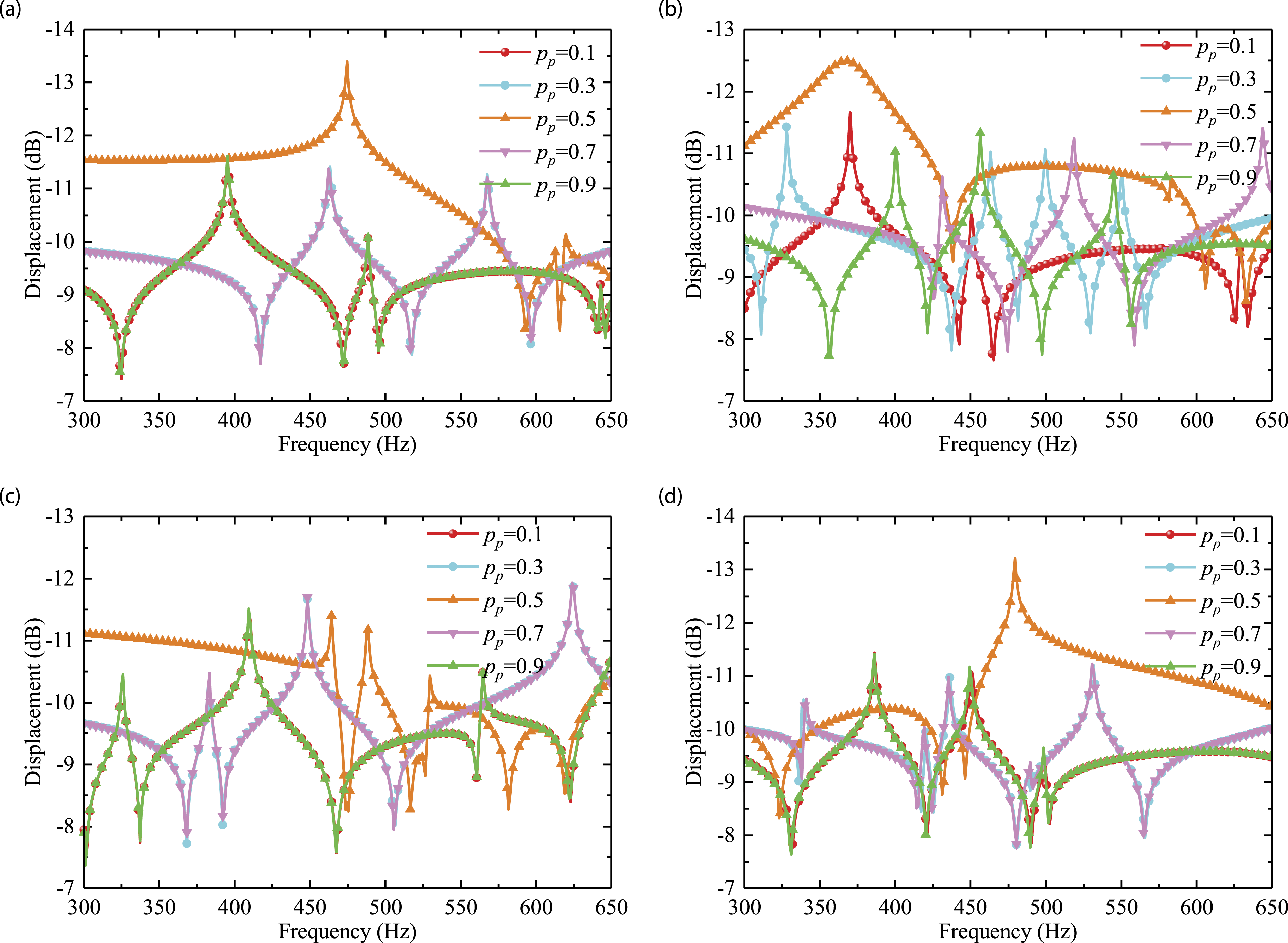
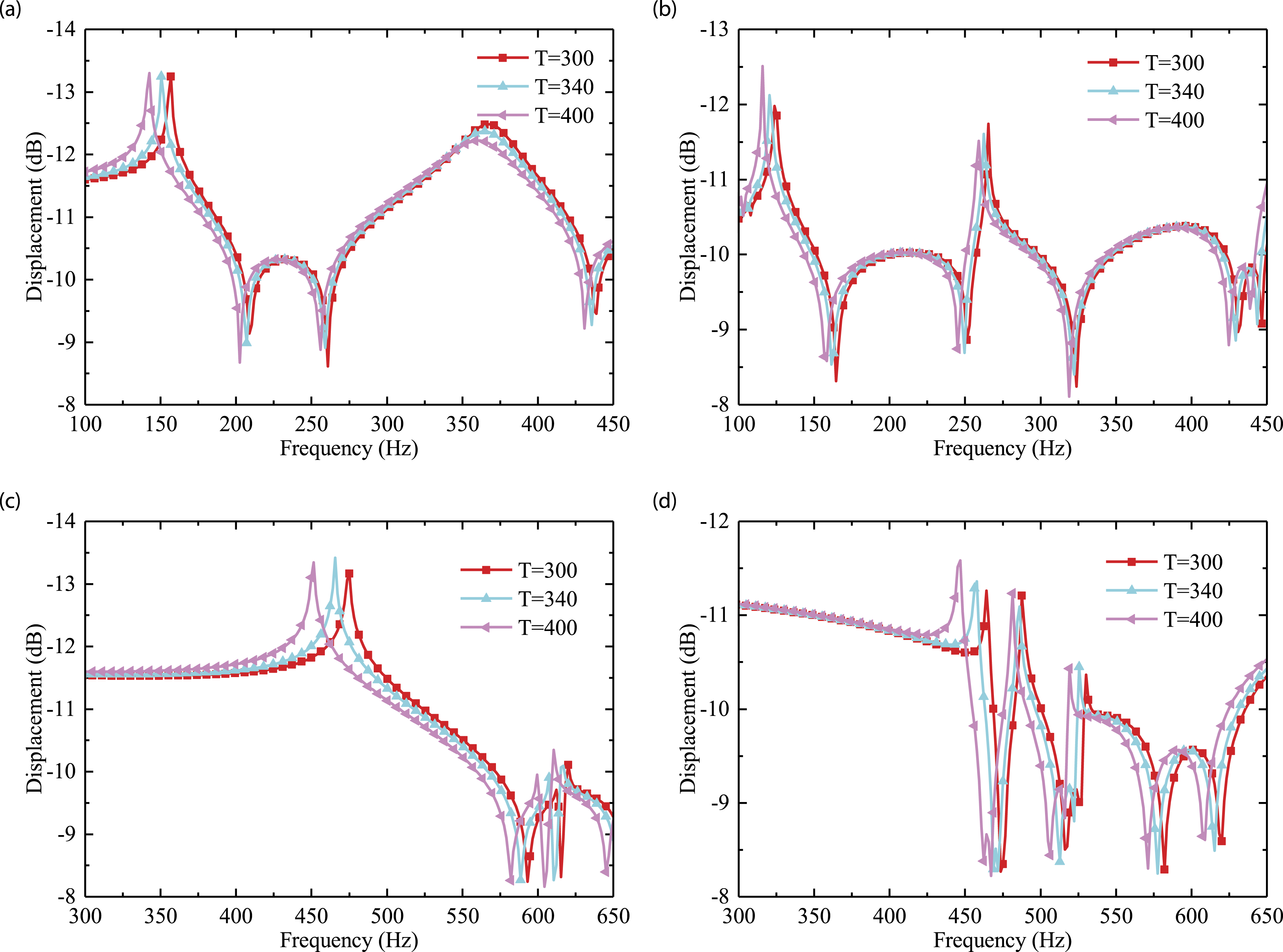
For sake of completeness and comprehensiveness of numerical results, steady state response behavior in the thermal environment is depicted in Figure 19. Boundary conditions, loading and measure and geometric parameters are same as Figure 15. As seen from Figure 19, lager difference between T and reference T0 makes the peaks of displacement move to higher frequency region.
Conclusions
In this article, an analysis model is established to investigate the FGM-stepped cylindrical shell coupled with annular plate in the thermal environment. According to the Chebyshev polynomial of first kind, the displacement fields are expanded. Compared with these results from the FEM model and the reference, sets of numerical examples are conducted to confirm the correctness and accuracy of the current method. Consequently, comprehensive and detailed investigations for influence of major factors are presented, including the geometric parameters, boundary conditions, loadings, coupling position, and temperature. And then, corresponding conclusions are obtained as the following: (1) For free vibration: more shell segments benefit free vibration of the FGM-stepped cylindrical shell coupled with annular plate at low frequency; frequency parameter of the shell–plate combination decreases with increasing temperature and the length L. (2) For transient response: transient response of the FGM-stepped cylindrical shell coupled with annular plate varies evidently owing to different excitations; meanwhile, the number of cylindrical shell segments and inner diameter r
p
which is not equal to 0 do hardly affect the transient response of the shell–plate combination; higher temperature leads lager displacement, but it does not work much; longer cylindrical does harm to the transient response of the shell–plate combination. (3) For steady state response: as length L of cylindrical shell of uniform thickness increases, peaks of displacement are more concentrated in the frequency region from 300 Hz to 650 Hz; with increments of r
p
, peaks of displacement shift to low frequency region; shell segments number plays little role in steady state response of the coupled structure, while distribution of shell segments works; better steady state response properties can be obtained by placing the annular plate in the middle of the cylindrical shell; lager difference between T and reference T0 makes the peaks of displacement move to higher frequency region.
Footnotes
Declaration of conflicting interests
The author(s) declared no potential conflicts of interest with respect to the research, authorship, and/or publication of this article.
Funding
The author(s) disclosed receipt of the following financial support for the research, authorship, and/or publication of this article: The authors gratefully acknowledge the financial support from the National Natural Science Foundation of China (Grant Nos. 51705537) and the Natural Science Foundation of Hunan Province of China (2018JJ3661). The authors gratefully acknowledge the supports from State Key Laboratory of High Performance Complex Manufacturing, Central South University, China (Grant No. ZZYJKT2018-11).
Appendix 1
The specific expressions of the total kinetic energy of the coupled stepped cylindrical shell–annular plate are given by
Appendix 2
The total stiffness and mass matrices are
The specific expressions of
The mass matrix
Also, the stiffness and mass matrix of the jth annular plate can be derived from
The expressions of