
Abstract
As a key component of satellite flexographic printing equipment, the vibration characteristics of the central impression cylinder have an important effect on the product quality. In order to improve dynamic characteristic of the central impression cylinder, the modal analysis on the central impression cylinder is carried out in combination with finite element software in this paper. Then, the modal properties are systematically compared between the central impression cylinder with circulating cooling water and without. The results show that the natural frequency of the central impression cylinder is greatly reduced based on the fluid–solid coupling method. Simultaneously, the natural frequencies and mode shapes of the central impression cylinder based on the finite element analysis are verified by an experimental test. The simulation results are in good agreement with the experimental results, indicating the effectiveness of the finite element model and experimental method used in this study.
Introduction
Modern rotating machinery and equipment are usually complex systems consisting of mechanical–electrical–fluid coupling. Due to the high operating speed, nonlinear vibrations are present in various rotating machinery, such as printing machines, turbines, etc. In particular, flexographic printing has become one of the most important printing equipment in the printing and packaging industry. The central impression cylinder, which is one of the core parts of flexographic printing machine, has the characteristics of large volume, complex structure, and high accuracy requirements. Moreover, unlike other printing machines, the special circulating cooling water system of flexographic printing machines will have an important influence on the dynamic characteristics of the cylinder.1,2 Hence, the nonlinear dynamic behavior of the central impression cylinder is a significantly important research.
The methods that are used for analyzing the nonlinear vibration 3 have been intensively studied by many researchers in recent years. The nonlinear vibration governing equations can be commonly solved by the variational iteration method, the homotopy perturbation method, the Taylor series method, etc. 4 The semi-inverse method was used to establish three-dimensional (3D) unsteady potential flow by He 5 and it overcame the Lagrange crisis also. He and Sun 6 demonstrated the effectiveness of the semi-inverse method for establishing the variational principle of practical problems by using the semi-inverse to establish a variational formulation for the thin film equation. Claude et al. 7 obtained the damped vibrations of a vibroacoustic interior by using a high order Newton solver, based on homotopy and perturbation techniques. Li–He’s variational principle was modified for plasma by He. 8 Considering the reproduction of both free and forced vibration experiments, a new wake oscillator model was proposed for modeling the vortex-induced vibration by Qu and Metrikine. 9 Gao et al. 10 designed an experimental device for deeply understanding the complex nonlinear vibration phenomenon of coupled rub-impact fault rotors under flight maneuvers.
Many researchers have applied analytical modal analysis, which is based on finite element method, for studying the dynamic characteristics of mechanical equipment 11 and for obtaining its modal parameters. Yao 12 investigated the dynamic features and natural frequency of central impression cylinders with the help of the ANSYS Workbench software. Wang et al. 13 established the dynamic mathematical model of torsional vibration at printing cylinder by using optimized particle swarm optimization algorithm. Analytical modal analysis is based on finite element method for obtaining the modal parameters of the structure. Chakravarty and Albertani 14 analyzed the modal characteristics of a latex membrane for micro air vehicle applications based on finite element models. Huang et al. 15 derived a governing equation for fiber crimp considering the thermal effect by using the Hamilton’s principle, and obtained the natural frequency and critical axially moving velocity. Despite the effectiveness of analytical modal analysis demonstrated by many works, whether such a model can predict the modal parameters with a high level of accuracy is questionable due to the effect of the grid. Furthermore, a lot of calculation cost to perform these simulations will be demanded in the case of analyzing large structures.
In recent years, with the continuous improvement of test equipment and algorithm programs, experimental modal analysis has been widely used in practical engineering to verify the accuracy of the modal parameters obtained by the finite element method. Kim et al. 16 proposed a novel method for monitoring the structural health. A testing using operational modal analysis with numerical-sensor signals for obtaining modal parameters was performed.
However, during the real operation of the flexographic printing machine, the temperature between the color groups is as high as 300℃ to quickly dry the surface of the substrate, which will lead to a temperature rise in the cylinder. Due to the high temperature, the central impression cylinder may become deformed. Thus, the central impression cylinder usually achieves the aim of heat dissipation by the flow of cooling water. Moreover, studies concerning fluid–solid coupling of the circulating cooling water are even fewer. Zhang et al. 17 studied the fluid–structure interaction simulation analysis of U-shaped tubes. The corresponding experiment was carried out to confirm the simulation results. Wang et al. 18 analyzed the water cooling temperature field as well as the flow field of water-cooled magnetic coupler based on the fluid–solid coupled heat transfer. Santo et al. 19 examined the dynamic load and stress analysis of a wind turbine considering the influence of gravity. At present, much less researches on the vibration characteristic analysis of central impression cylinder with circulating cooling water can be found. Thus, a fluid–solid coupling method is proposed to investigate the dynamic response of the central impression cylinder20–23 with the effect of the cooling water.
Therefore, ANSYS Workbench simulation platform is employed to conduct modal analysis based on the fluid–solid coupling of the central impression cylinder. Basic theory is described in the next section; in the “Calculation model and boundary condition setting” section, the finite element model of central impression cylinder is established; numerical calculation and analysis is in the “Numerical simulation results and analysis” section; further, in the “Modal analysis of central impression cylinder test” section,an experimental test is used to verify the modal parameters obtained by finite element method; and the conclusion is listed in the final section.
Basic theory
An analytical method is used to describe the structural dynamic property according to the modal parameters like the natural frequencies and mode shapes of an object, which is known as modal analysis.
24
The dynamic equation of the central impression cylinder under forced excitations can be written in the form

The relative position of the cooling water with the inner- and outer-wall of the cylinder is shown in Figure 1. The cooling water also rotates at a high speed with the cylinder and it will greatly affect the vibration frequency of the cylinder. As a result, the mass of fluid should be considered in the vibration characteristic analysis of the central impression cylinder

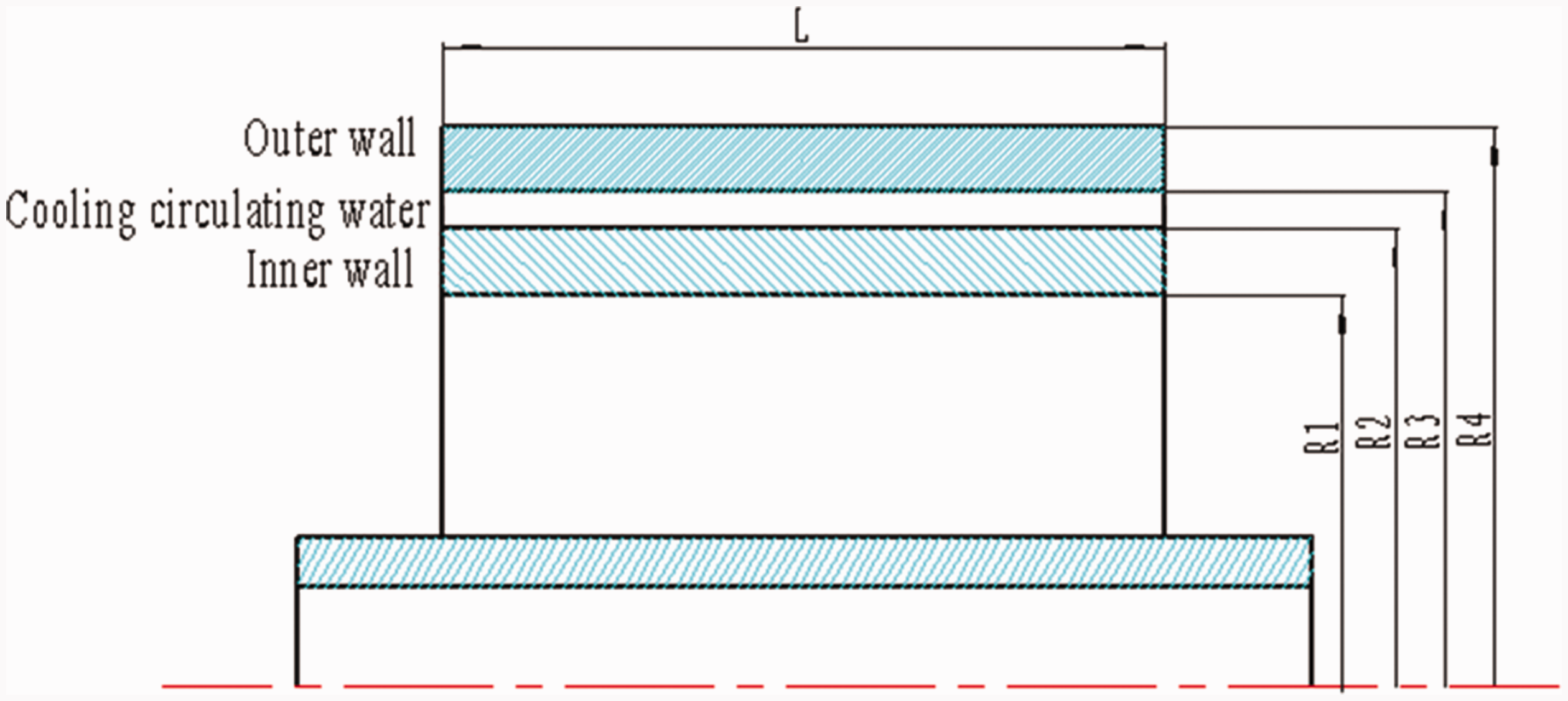
The relative position of the cooling water with the inner- and outer-wall of the cylinder.
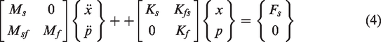
Based on the above expressions of the structural dynamics and fluid dynamics equations, the fluid–solid coupling vibration equation can be written as follows

Then, suppose the cylinder is subjected to free vibration, equation (3) can be written as follows
Calculation model and boundary condition setting
Finite element model establishment of central impression cylinder
Typically, the first step in finite element modal analysis is pre-processing, which involves creating 3D model, assigning material properties to the 3D model, meshing the model, and defining the appropriate boundary conditions. Therefore, the present paper takes the central impression cylinder as the object of study. As shown in Figure 2, a simplified 3D assembly model of the central impression cylinder is created by SolidWorks software, on the basis of actual dimensions of cylinder at first.
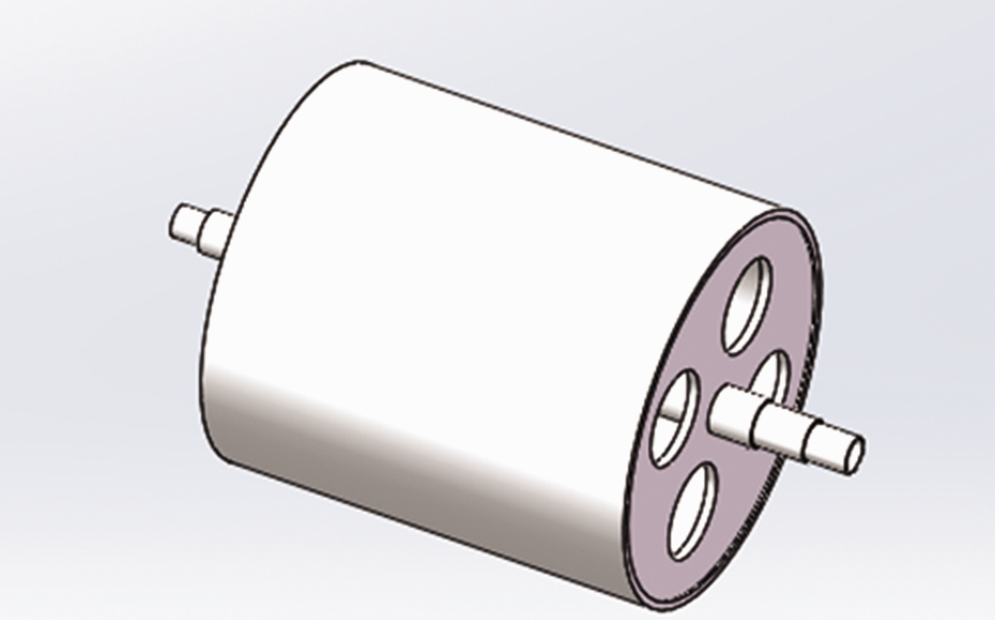
A simplified 3D assembly model of central impression cylinder.
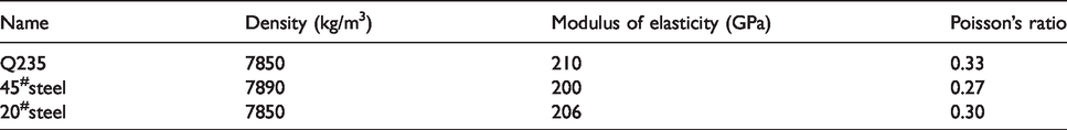
Then, some material properties of the central impression cylinder such as density, modulus of elasticity, and Poisson’s ratio, which are listed in Table 1, are necessary for finite element simulation, and the material properties should be set separately in accordance with Table 1.
Some material properties of the central impression cylinder.
After assigning the material properties, designed model is meshed. Meshing is a crucial step in finite element numerical simulation analysis, which can directly affect the accuracy of subsequent numerical analysis results. In the Gambit software, solid structure is divided by a tetrahedral mesh method while 3D fluid element is used for fluid part. As a result, the meshed model of the central impression cylinder is as shown in Figure 3.
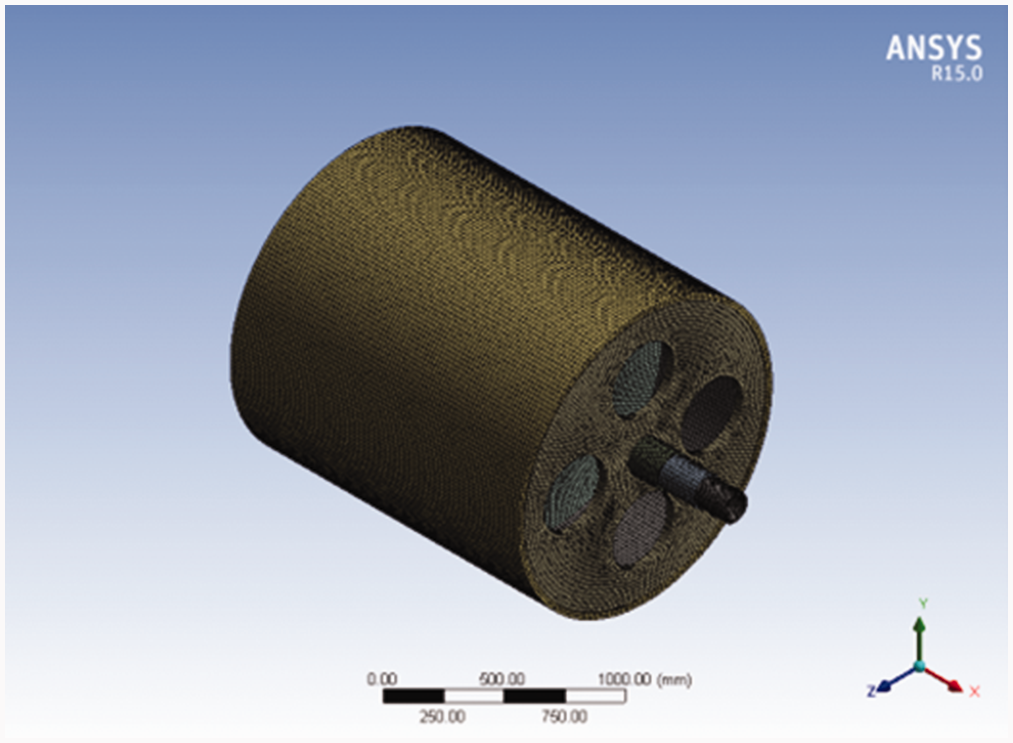
Finite element model of central impression cylinder.
Boundary conditions’ definition
The present paper adopts the standard k–ω turbulence model. Additionally, the inlet is set to be the actual inflow velocity of cooling water. As for the outlet, it is set to be standard atmospheric pressure. At the same time, the boundary of fluid domain is set as the slip boundary to eliminate the influence of solid boundary on fluid.
When cooling water is not considered, the Workbench is directly used for modal calculation. However, the fluid–solid coupled model is adopted if the cooling water is considered. Also, it is necessary to apply the calculated load of fluid to the solid of the cylinder for calculation. At last, the reasonable constraints are added at both ends of the bearing to simulate the operation of the cylinder.
Numerical simulation results and analysis
The fluid load is calculated before adopting the fluid–solid coupled modal. From the FLUENT analog simulation, the results in Figures 4 and 5 are obtained.
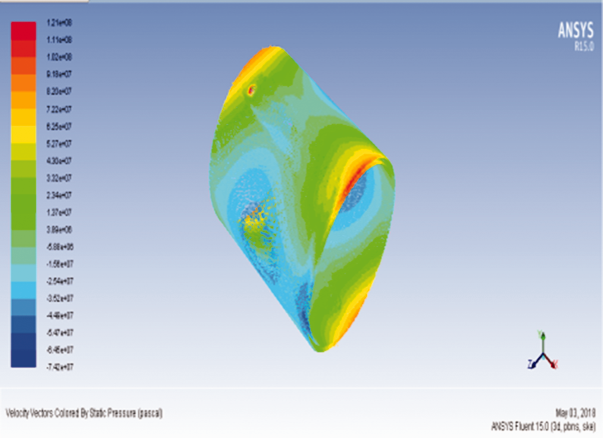
Pressure cloud diagram of cooling water field.
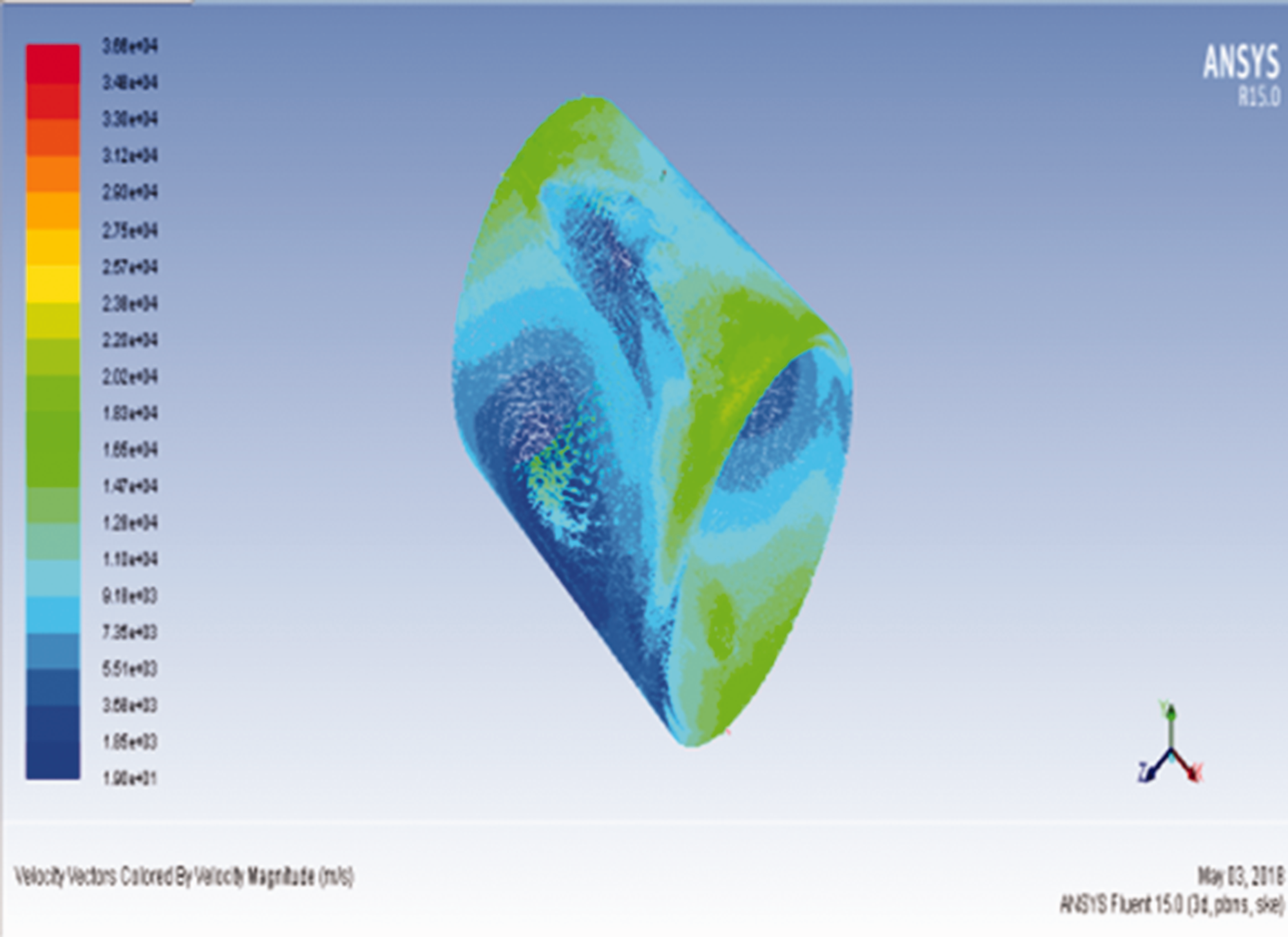
Velocity cloud diagram of cooling water field.
Figure 4 shows the pressure distribution map of the cooling water field. From the figure, it can be seen that the inlet and outlet pressures are relatively large, and the pressure distribution between the fluid domains is also relatively uniform, which ensures the uniformity of the fluid flow. Then, the velocity nephogram of the cooling water can be observed as shown in Figure 5. From the overall velocity distribution, the velocity in the fluid domain is relatively average, and a high velocity is generated around the inlet, with a maximum velocity of 3.6 m/s, whose velocity is relatively higher than the other parts. In addition, the calculated results of the fluid domain are loaded onto the inner and outer wall surfaces of the roller structure for modal analysis under prestress.
The results of finite element modal analysis for the central impression cylinder are obtained in the form of natural frequencies and mode shapes. Since the lower modes are more important and contributory, the modes of first to sixth are considered for further study.
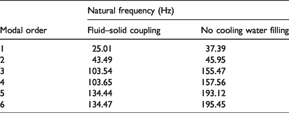
Table 2 indicates the value of natural frequencies of the cylinder. 25 The first vibrational modes of “dry” cylinder are obtained at about 37.39 Hz, and this value is 25.01 Hz for “wet” cylinder. Compared with the “dry” cylinder, the natural frequencies of the “wet” cylinder are significantly reduced, and the maximum reduction is 52.0%. In addition, by calculating the first natural frequency, the critical speed of 1500 r/min is far more than the working speed of the central impression cylinder, proving the avoidance of resonance.
Natural frequencies of six orders wet and dry vibration modes of the central impression cylinder.
The mode shapes are used to draw the displacement curve of the node during the vibration of the structure in the frequency domain. Figures 6 and 7, respectively, present the first six-order vibration modes of cylinder in the case of cooling water and without cooling water. According to FEM simulation, the first two modes are the deformed modes and occur on the surface part of the cylinder. Mode number 3 and 4 are the middle bending and S-bending modes. However, the fifth and sixth modes have larger deformation and torsional bending than the first four modes.
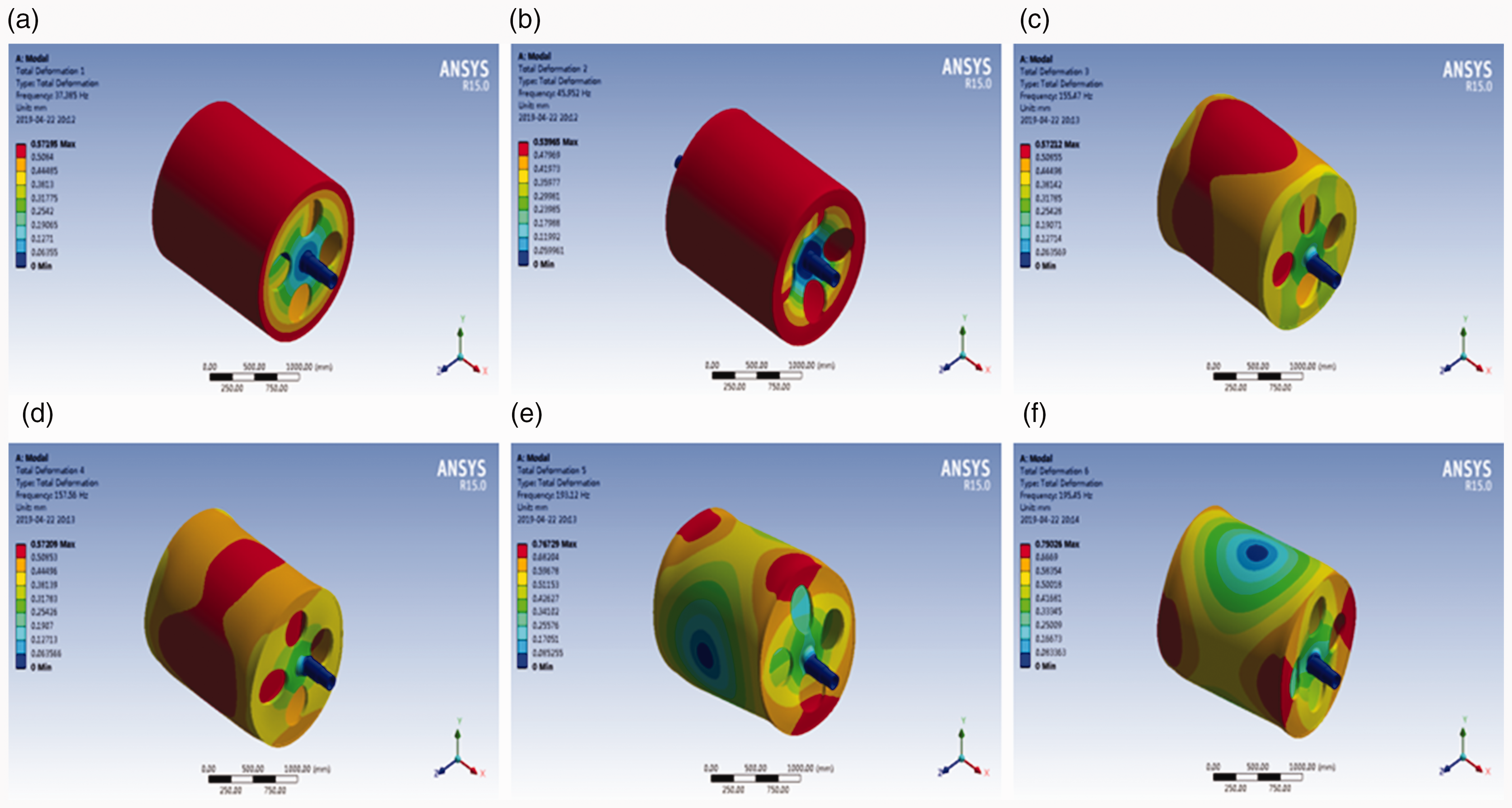
The six orders vibration mode shapes of the central impression cylinder without cooling water filling. (a) First-order vibration mode, (b) second-order vibration mode, (c) third-order vibration mode, (d) fourth-order vibration mode, (e) fifth-order vibration mode, and (f) sixth-order vibration mode.
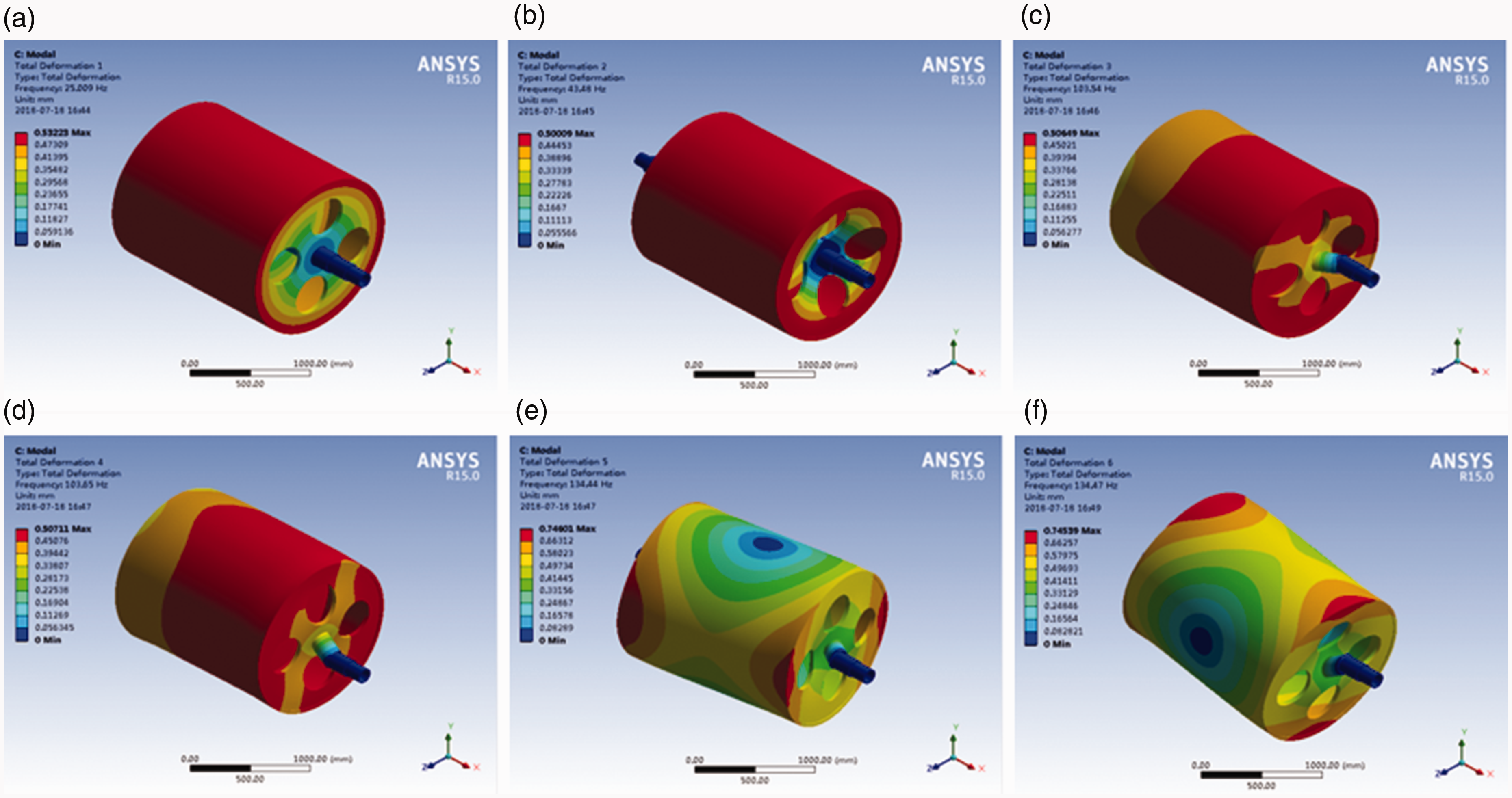
The six orders vibration mode shapes of the central impression cylinder under fluid–solid coupling state. (a) First-order vibration mode, (b) second-order vibration mode, (c) third-order vibration mode, (d) fourth-order vibration mode, (e) fifth-order vibration mode, and (f) sixth-order vibration mode.
Actually, the modulus of elasticity, density, and Poisson’s ratio are the relational parameters on the natural frequency value. Therefore, the values of “dry” natural frequency and “wet” natural frequency are obviously different, while the mode shapes of these two types of the central impression cylinder are consistent, except that the surface deformation of the cylinder is significantly reduced under the fluid–solid coupling interaction.
Modal analysis of central impression cylinder test
Experimental modal analysis related theory
The experimental modal analysis 26 generally stimulates the central impression cylinder structure through the excitation device; the frequency response function curve of the system is obtained by measuring the excitation input and response output signals of the cylinder structure. To perform it, the technique that an input–output type of modal analysis technique is presented in this paper, that is, both the input exciation and the output response of the system are all used for the estimation of the FRF. The vibration signals obtained from the experiment were recorded and analyzed by curve fitting method, then the modal parameters of each order are obtained, 27 which provides the basis for the follow-up structural dynamic analysis and optimization improvement. 28
In the experimental modal analysis, applying the Fourier transform on both sides of equation (1) will yield equation (5)
According to equation (5), the frequency response function can be written as
When the excitation is given at point j and the response is measured at point i, then the element in the j-th row and i-column of the frequency response function matrix can be expressed as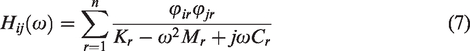
The FRF element contains the pole and residue information at any measuring point of the system, that is all the information of mode shape, natural frequency, and damping ratio. Therefore, all modal parameters of the system can be obtained by using the frequency response function matrix and its single element.
Experimental modal testing system
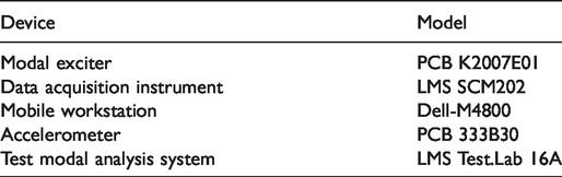
In order to determine the accuracy of the natural frequencies and mode shapes of the central impression cylinder obtained by finite element simulation, an experimental platform is established for verification and analysis. Experiments are performed on the central impression cylinder of flexographic printing machines. 29 As listed in Table 3, the experimental platform is composed of modal exciter, data acquisition instrument, mobile workstation, accelerometer, and test modal analysis system. To estimate the modal properties, an impact excitation should be given by a modal exciter at a location on the cylinder during experiment. At the same time, the channels of the data acquisition system are used for the exciter and accelerometers to collect the vibration signal. Moreover, LMS Test.Lab 16A is prepared for estimating the FRF by processing the collected signal, and then the modal parameters are identified.
Apparatus for test.
In order to perform experimental modal analysis, for modal parameter estimation, the input excitation and output response of the system should be measured to estimate the FRF. During the model test, integrity modal parameters are obtained through the single-input multi-output analysis method. The picture of the experimental setup is as shown in Figure 8.
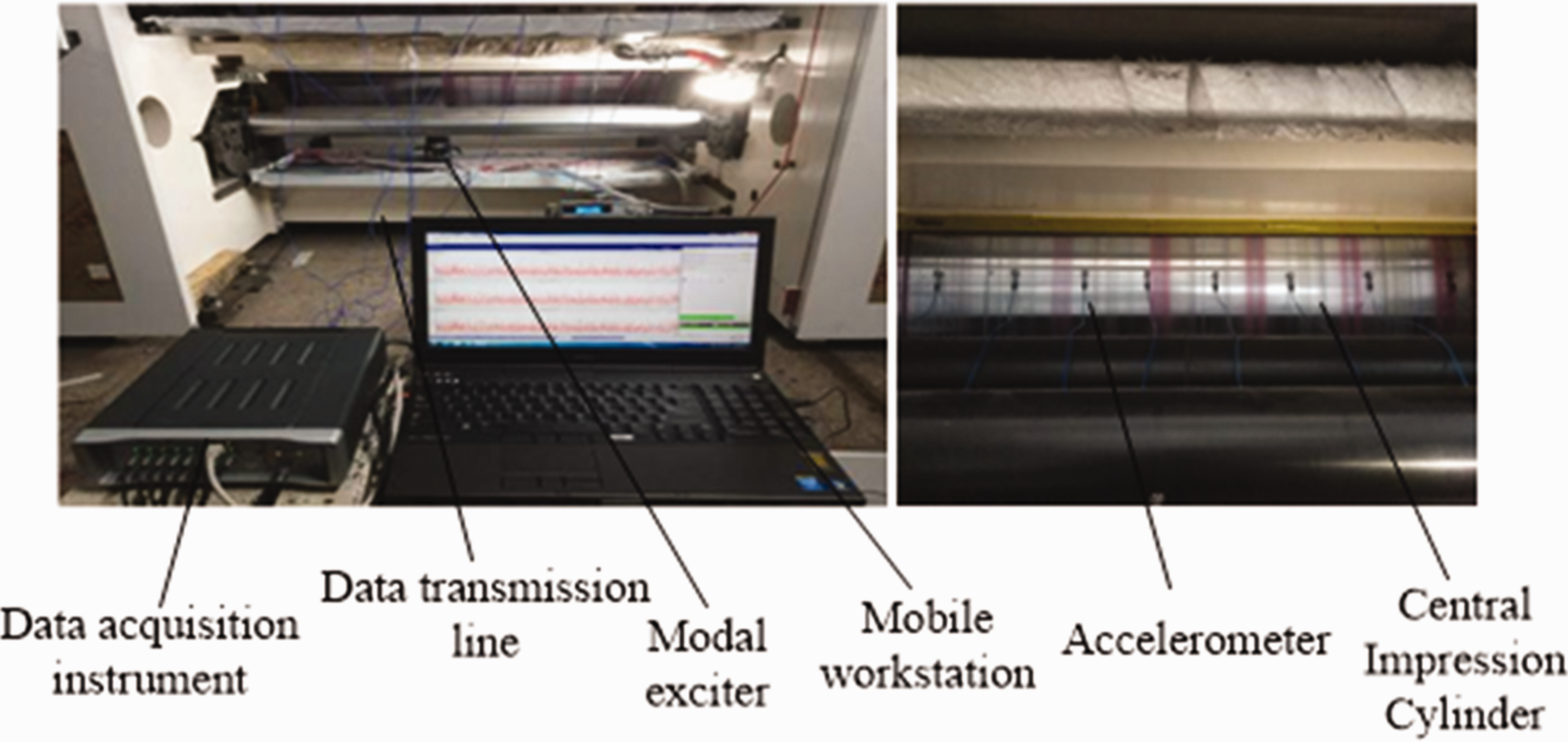
Experiment modal of central impression cylinder.
According to the surface vibration mode of the central impression cylinder, combined with the deformation characteristics of the structure, eight measuring points are evenly arranged on the surface of the central impression cylinder in the axial direction, and the layout of the testing points of the central impression cylinder is as shown in Figure 9.
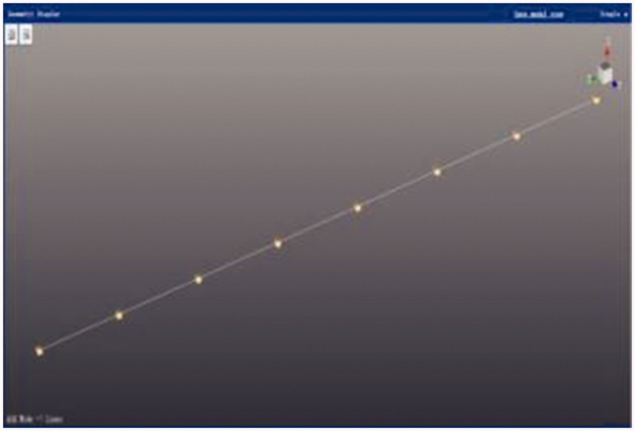
Test points distribution.
The results of experimental modal testing
Before starting the test, the channel setting, oscilloscope, and test parameters should be set at first. Then, several pre-acquisitions are carried out to ensure the accuracy of the test results, and the formal collection is started while various test parameters are relatively reasonable. After checking and saving the collected data of all the measuring points, the FRF of each measuring point will be obtained. Additionally, to identify the modal parameters precisely, here, identification has been carried out using the rational fractional polynomial frequency domain identification method and ARMA time series time domain identification method, respectively.30,31 The values of the first six frequencies identified by the above two methods are shown in Table 4, while the corresponding mode shapes are as shown in Figures 10 and 11, respectively.
Experiment modal frequency of central impression cylinder.
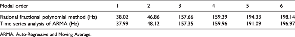
ARMA: Auto-Regressive and Moving Average.
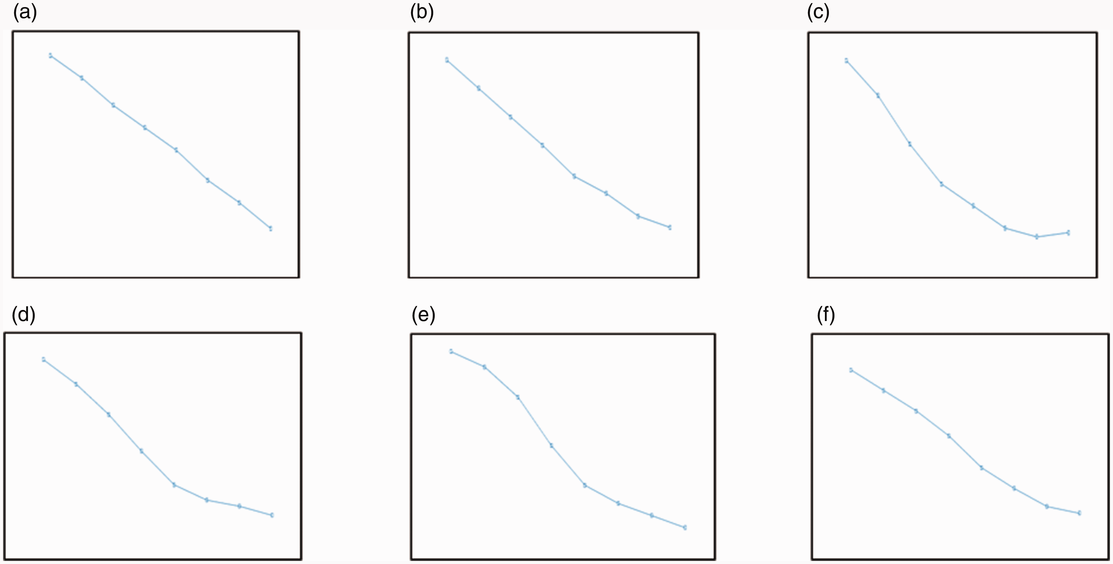
Rational fractional polynomial method for identifying the first sixth mode. (a) The first order mode, (b) the second order mode, (c) the third order mode, (d) the fourth order mode, (e) the fifth order mode, and (f) the sixth order mode.
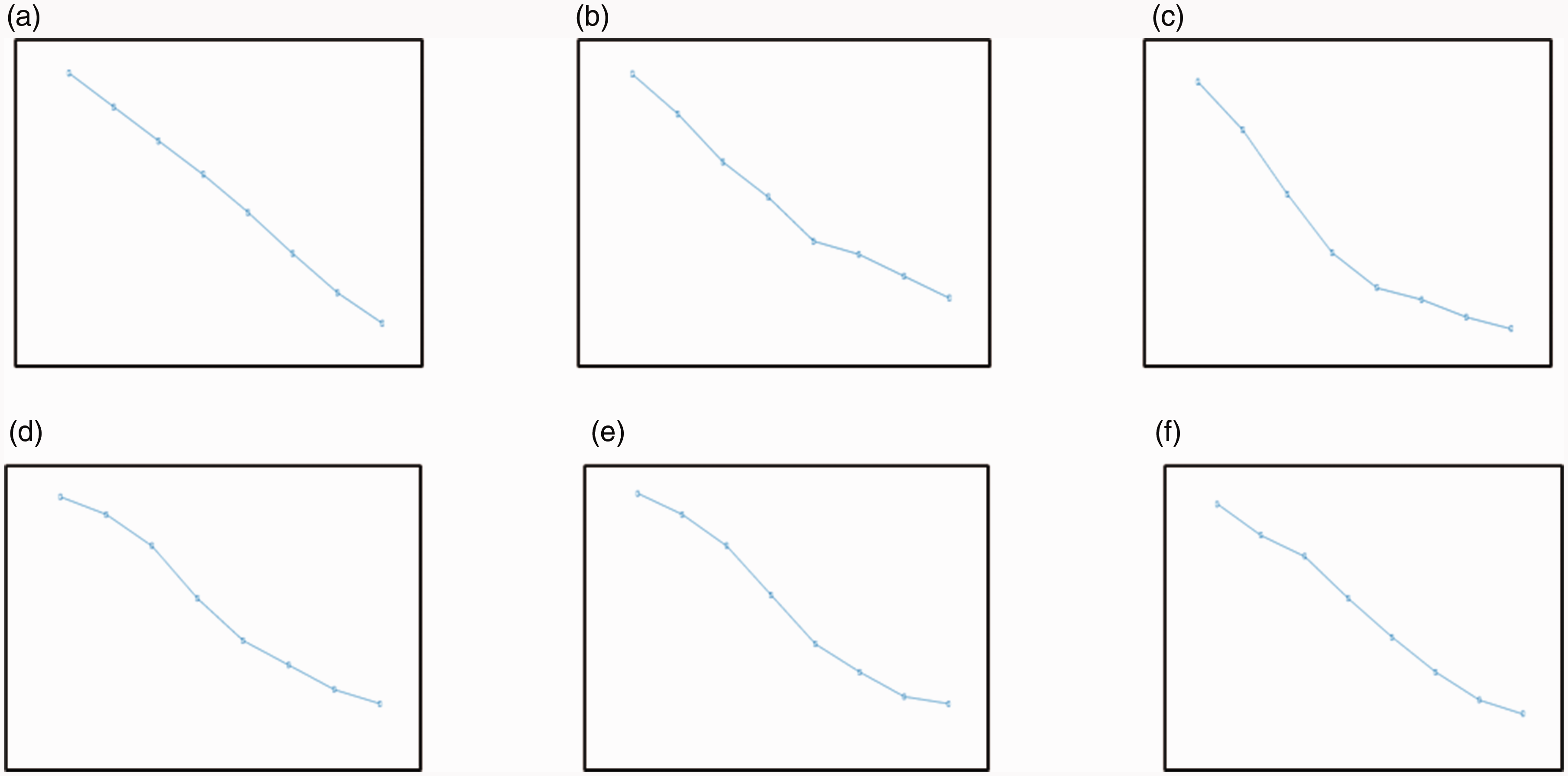
ARMA model time series analysis for identifying the first sixth mode. (a) The first order mode, (b) the second order mode, (c) the third order mode, (d) the fourth order mode, (e) the fifth order mode, and (f) the sixth order mode.
In order to obtain a validation of the finite element model, the comparison between the experimental frequency and the simulation frequency is drawn. As can be seen in Table 5, the natural frequency differences between the simulation value and experimental value are both within 5%. The error is within the permissible range, indicating the correctness of the finite element model of central impression cylinder.
Comparison of natural frequencies.
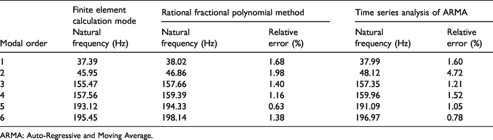
ARMA: Auto-Regressive and Moving Average.
Conclusion
Using the finite element method, a modal analysis is carried out for the central impression cylinder, and the first six natural frequencies and mode shapes are obtained. The results show that the working speed of the cylinder is far less than the critical speed, which can effectively avoid resonance. By analyzing the mode shapes, the weak parts in the design of the cylinder can be found, which can lay a foundation for the optimal design of the central impression cylinder.
The circulating cooling water has an important influence on the vibration characteristic of central impression cylinder. To simulate the cylinder in real operation, the fluid–solid coupling method is used to analyze the modal characteristic. The analysis results show that the natural frequency of the cylinder is greatly reduced due to the presence of cooling water, and the vibration of the cylinder is significantly improved.
The experiment is used to verify the modal parameters obtained by finite element method; the maximum quantitative values are less than 5% of relative errors between experiment and simulation, which proves the correctness of the finite element model of central impression cylinder. Therefore, the finite element model and experimental method used in this paper can be used as a cost-effective and reliable method for the design and vibration characteristic analysis of the central impression cylinder of flexographic printing presses.
Footnotes
Declaration of conflicting interests
The author(s) declared no potential conflicts of interest with respect to the research, authorship, and/or publication of this article.
Funding
The author(s) disclosed receipt of the following financial support for the research, authorship, and/or publication of this article: This project is supported by the Technical Innovation Guidance Plan (Grant No. 2020QFY03-05 and 2020QFY03-03), National Natural Science Foundation of China (Grant No. 51905420), and China Postdoctoral Science Foundation (No. 2019M663783).