
Abstract
In order to reduce the natural frequency of the piezoelectric vibration energy harvester, improve performance of the piezoelectric vibration energy harvester, and meet the requirements of energy acquisition in the low-frequency vibration environment, a variable-section circular piezoelectric vibration energy harvester is presented. The dynamic model and electromechanical coupling model of variable-section circular piezoelectric vibration energy harvester are established. The main factors affecting the output performance of piezoelectric vibration energy harvester are analyzed. The structure parameters of piezoelectric vibration energy harvester are optimized by orthogonal experiment. An experimental platform is built to test output voltage and output power of piezoelectric vibration energy harvester. The experimental results show that when the number of energy harvester is 4 and the external load is 180KΩ, the parallel output power can reach 0.213mW, which can meet the requirements of micro-power device power supply.
Introduction
In recent years, the related self-powered technology has been promoted greatly with continuous development of micro-power electronic device.1–3 Chemical battery is a traditional power supply method, but chemical battery has the disadvantages of large volume, limited service life, and difficult to replace under special circumstances, which limits the application of chemical batteries. 4 –5 Capturing energy in the environment to power micro-power electronic device becomes an effective solution.6–9 Vibration energy has received extensive attention due to its abundant stock and high energy density.10–14 According to the different conversion mechanisms, the vibration-electric energy harvester are generally divided into three types, namely piezoelectric type, electrostatic type and electromagnetic type.15–19 However, piezoelectric vibration energy harvester has the advantages of simple structure, easy miniaturization and low heat generation, which makes it a research hotspot.
In the structure research of piezoelectric energy harvester, the classical rectangular cantilever beam structure has the disadvantages of low acquisition efficiency, low output voltage, and low power.20–23 In order to solve the above problems, a miniature equal-strength beam piezoelectric vibration energy harvesting structure is proposed by Liu. 24 Compared with the traditional equal-section piezoelectric vibration energy harvesting structure, the equal-strength piezoelectric vibration energy harvester has the advantages of low natural frequency, reasonable surface stress distribution and pressure, high utilization rate of piezoelectric materials, and high energy output density. A magnetic frequency modulation piezoelectric electromagnetic composite energy harvesting device is designed by Du. 25 By changing the distance between the magnetic mass and the magnets, the equivalent stiffness of the piezoelectric beam can be adjusted to match the frequency of the environmental vibration frequency and improve the efficiency of energy harvesting. Bottom planar coil is based on the principle of electromagnetic induction to harvest electric energy and realize the acquisition of piezoelectric and electromagnetic composite vibration energy, but greatly increases size and complexity of the structure, which is not conducive to application in practical environments. A common mass piezoelectric array structure is proposed by She. 26 The experimental results show that output power is basically equal under the same excitation conditions, and output voltage of the series structure is greatly increased, but the acquisition frequency band is not improved. A nonlinear multimode wideband piezoelectric vibration energy harvester is designed by Sharvari. 27 The experimental results show that there are multiple vibration modes at lower frequencies. Flexible structure is adopted to broaden the frequency band width and increase the output voltage of the structure. A piezoelectric energy harvester driven by human limbs is proposed by Miah. 28 The experimental results show that under optimal load conditions, each single piezoelectric harvester produces an average power of 96 µW, while at 4.96 Hz and 2 g acceleration. Devices with series harvester can produce a maximum average power of 175 µW.
In view of the above mentioned structural defects, a variable-section circular piezoelectric vibration energy harvesting structure is proposed to improve the practicality of piezoelectric vibration energy harvesting in this paper, which uses a variable cross-section beam structure instead of an equal cross-section beam structure to reduce the natural frequency of the piezoelectric vibration energy harvesting device. The main structure of this paper is as follows. First, the dynamic model and electromechanical coupling model of variable-section circular piezoelectric vibration energy harvesting device are established, and the main influencing factors of the output performance of piezoelectric vibration energy harvester are analyzed. Second, the orthogonal experiment is designed to optimize structural parameters of the piezoelectric vibration energy harvester. Finally, an experimental platform is built to test output voltage and output power of the piezoelectric energy harvester.
Theoretical analysis
Dynamic model
In order to theoretically analyze the dynamic characteristics of the variable-section circular beam structure, the dynamic model is established, and the modeling conditions are simplified as follows: the shear deformation and vibration damping of beam are neglected and the length and width of piezoelectric sheet are equal to length and width of beam, respectively.
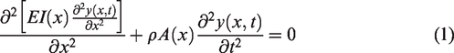
The length is l, the axial vibration and transverse vibration directions of the beam are the x and y directions, respectively. And the transverse displacement of any point on the neutral axis is y(x, t). The meanings of other parameters in this article are listed in Table 1. Then free vibration equation under the inertial system can be expressed by following formula
Glossary of parameters.
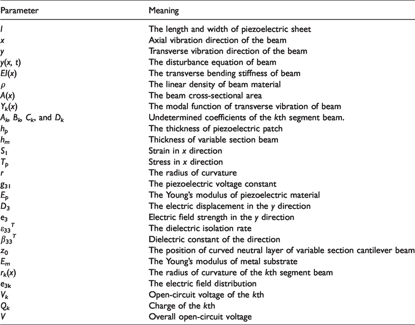
Among them: y(x, t) is the disturbance equation of beam, EI(x) is the transverse bending stiffness of beam, ρ is the linear density of beam material, and A(x) is the beam cross-sectional area.
We set y(x, t)=u(x, t). Recently, He
29
studied the following equation


According to equation (2), we can introduce a special function φ, satisfying the following relations.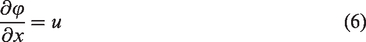

By the semi-inverse method,30,31 we can establish the following equation.

We consider a special case of equation (2)
Herby F(u) = −u, G(u) = −u2, H(u) = −u.
Equation (10) was first obtained by Joseph Boussinesq in 1987 for a long and unidirectional wave, which has a solitary solution.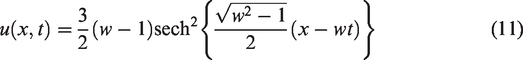
We introduce a complex variation ξ defined as
Substituting equation (12) into equation (10), we get an ordinary differential equation
According to some researchers32–34 such as Ji and He, the solution of equation (10) is as follows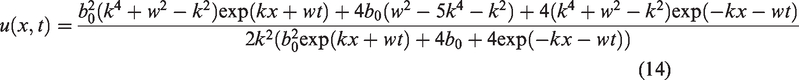
In this paper, the semi-inverse method is used to establish the variational formula of equation (2) for numerical analysis. Finally, the result of u(x, t) can be solved.
The variable-section circular shown in Figure 1 is divided into a combination of connected beams. When the number of beams is sufficient, each segment can be regarded as an equal-section beam. 35
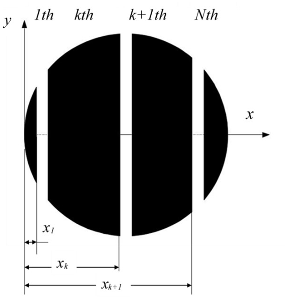
Multi-section equivalent beam.
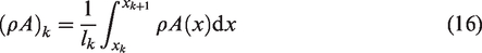
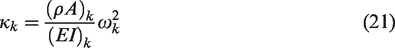
Among them, the equivalent bending stiffness and equivalent linear density of the kth segment beam can be expressed as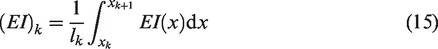
The free vibration equation of the kth segment beam can be expressed as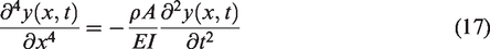
The variational formulation for equation (17) can be written as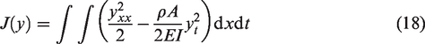
According to mechanical vibration knowledge, the vibration equation has the following form solution
Yk(x) is the modal function of transverse vibration of beam, with following form of solution
Similarly, the modal function of the k + 1th segment beam can also be expressed as
The kth segment beam and k + 1th segment beams have following geometrical relationship at point k


Substituting equations (20) and (22) into equations (23) to (26).
The undetermined coefficients of the kth segment beams and k + 1th segment beams are

Matrix Z(
k
) in equation (27) is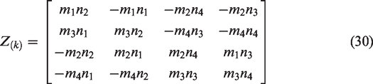
Among them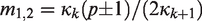


From equation (27), the relationship between Z(1) and Z(
N
) can be obtained as

According to the boundary conditions of cantilever beam, the characteristic equation of natural circular frequency of the transverse vibration of variable section beam is calculated. The boundary conditions of its displacement, rotation angle and force are as follows

From equation (33)

From equation (34)
Among them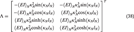
Substituting equation (33) into equation (39)
Among them
Combine equations (35) and (36) with equation (39) to solve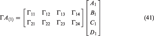
In order to make equation (41) have a non-zero solution, the determinant of coefficient matrix must be zero, and the characteristic equation of variable section cantilever beam is obtained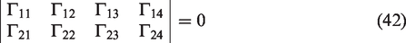
The characteristic equation (42) is a nonlinear equation of natural frequency. The result is brought into equations (20) and (27) to obtain the beam’s array function, which can qualitatively analyze the total modal frequency distribution state of beam.
Electromechanical coupling model
The piezoelectric sheet attached to metal substrate undergoes bending deformation during vibration. An alternating voltage is generated on both sides of the piezoelectric sheet, and alternating current is generated if an external circuit is connected. Yin et al. 36 provides the derivation process of the relationship between the vibration deformation and voltage of the single wafer piezoelectric cantilever beam. In order to simplify the calculation, the length and width of piezoelectric patch are respectively equal to length and width of beam.
Figure 2 is a schematic diagram of the electromechanical coupling model of the variable-section piezoelectric cantilever beam, where hp and hm are the thickness of piezoelectric patch and thickness of variable section beam respectively, and the relationship between stress and strain of piezoelectric patch.


Electromechanical coupling model.
In equations (43) to (45), S1 is strain in x direction, Tp is stress in x direction, r is the radius of curvature, g31 is the piezoelectric voltage constant, and Ep is the Young’s modulus of piezoelectric material, D3 and e3 is the electric displacement and electric field strength in the y direction, β33 T =1/ε33 T is the dielectric isolation rate, and ε33 T is dielectric constant in y direction.
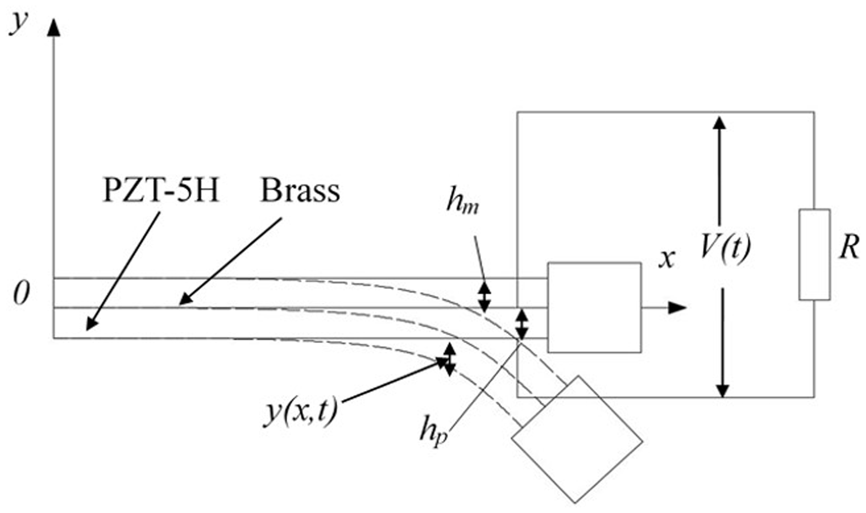
The position of curved neutral layer of variable section cantilever beam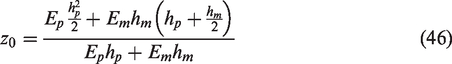
In the equation (46), Em is the Young’s modulus of the metal substrate.
In order to study the voltage acquisition effect of variable-section circular piezoelectric beam at resonance, the matrix function is analyzed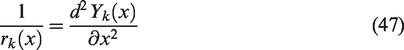
In the equation (47), Yk(x) is matrix function of the kth segment of piezoelectric patch, which can be solved by the above dynamic model analysis, and rk(x) is the radius of curvature of the kth segment beam.
The electric field distribution equation is solved by simultaneous equations (43) to (47)
Then the voltage equation is
The charge equation is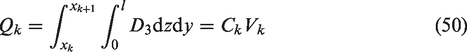
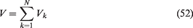
From (49) and (50), open-circuit voltage of the kth segment and overall open-circuit voltage can be solved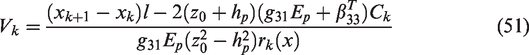
It can be seen that the voltage in the kth segment is inversely proportional to radius of curvature of segment from equation (51). When radius of curvature becomes smaller (i.e., the degree of curvature increases), the voltage value increases accordingly. Therefore, in the case of harmonic excitation at a certain frequency, the natural frequency of a piezoelectric beam is the same or close to excitation frequency (i.e., resonance or near resonance), the deformation is maximum at this time and the corresponding voltage value can reach maximum value. It provides theoretical basis for following experimental analysis.
Structure study
Finite element analysis
In this paper, modal analysis and piezoelectric analysis are performed on piezoelectric vibrators with the same area and different shapes. The shapes of these piezoelectric vibrators are circular, triangular, trapezoidal and rectangular (classical cantilever structure). Table 2 shows material parameters of the variable section piezoelectric energy harvester, in which PZT-5H is selected as the piezoelectric material of the piezoelectric patch attached to the piezoelectric vibrator and brass piece is selected as the variable-section piezoelectric cantilever beam substrate.
Material parameters of piezoelectric cantilever beam.
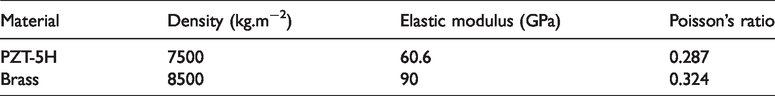
Figure 3 shows the natural frequencies of piezoelectric vibrators with same area and different shapes, it can be seen from Figure 3 that the circular piezoelectric energy harvester has the lowest natural frequency, while that the triangle is the highest. Figure 4 shows the open-circuit output voltage with same area and different shapes structure, it can be seen from the Figure 4 that the circular piezoelectric energy harvester has higher output voltage under same conditions.
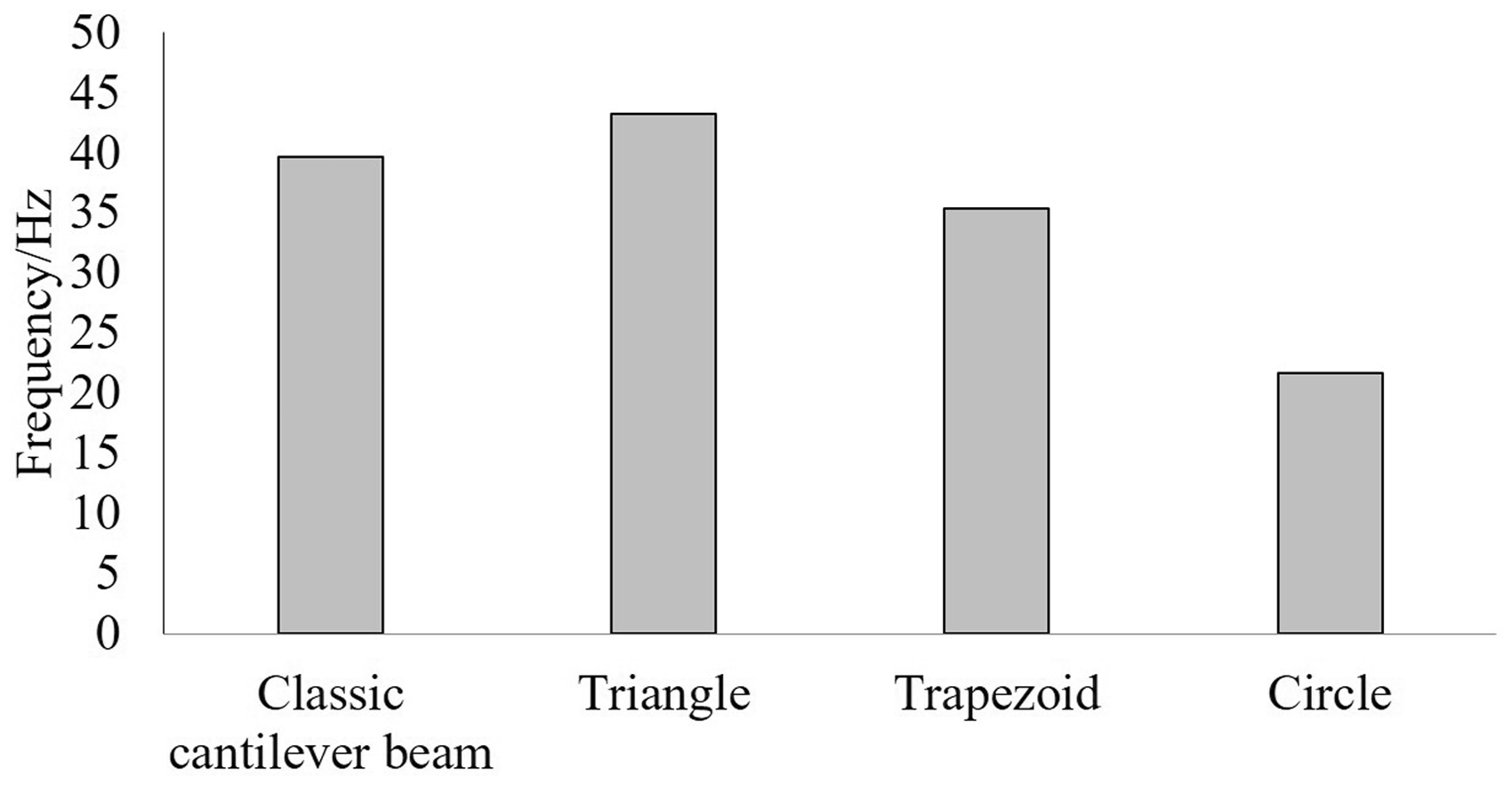
Natural frequency of different sections of piezoelectric cantilever beam.
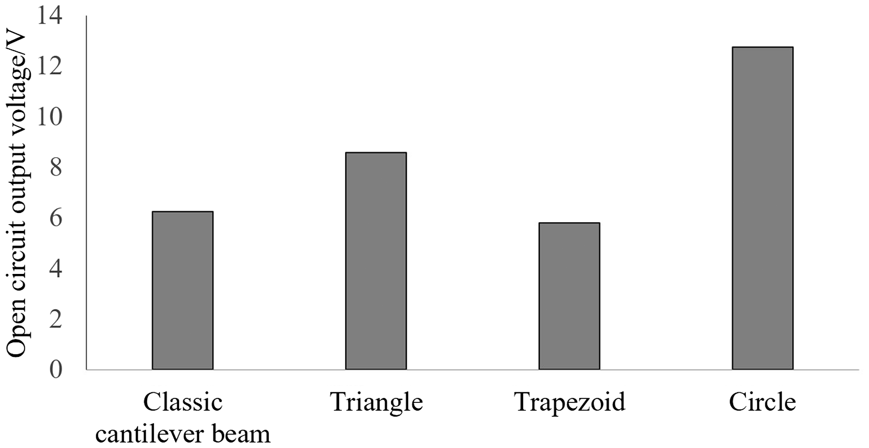
Output voltage of piezoelectric cantilever beam with different cross sections.
In summary, it can be seen that the variable-section circular piezoelectric cantilever is selected as harvesting structure of energy harvesting device in this experiment. Therefore, a variable-section circular piezoelectric energy harvester is designed, and its size structure is shown in Figure 5.
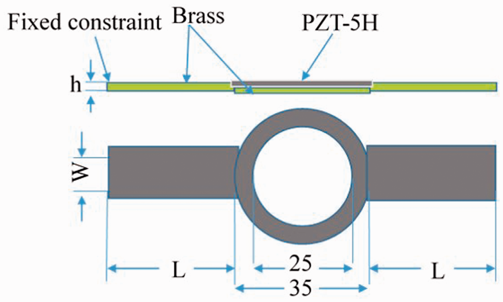
Variable section circular piezoelectric cantilever beam structure.
Parameter optimization
For any two factors in the process of experiment, it can be regarded as multiple experiments with same number of repetitions. With a small number of representative experiments, data that can fully reflect all experiments can be basically obtained, which solves the problem that single-factor rotation experiment method cannot comprehensively and quickly study the influence of various factors and their interaction. The orthogonal experiment method can be used to efficiently and quickly deal with multi-factor experiments, and the structural parameters are optimized according to the orthogonal experiment method.
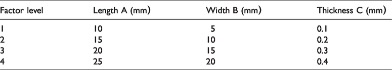
According to common size of low-frequency piezoelectric energy harvester,37,38 the length range selected in this paper is 10–25 mm, the width range is 5–20 mm and the thickness range is 0.1–0.4 mm. According to the range of each size, factors and level table of the orthogonal experiment shown in Table 3 are determined.
Orthogonal experiment factors and level tables.
In this orthogonal table, each column is a factor, but it can represent up to five factors. Each row represents one experiment, and a total of 16 finite element simulation analyses are required. The number in each row in the table represent the horizontal serial number of each factor, and each factor has four levels. The 16 experiments shown in the orthogonal table can comprehensively reflect the influence of various levels in various factors on natural frequency and open-circuit output voltage of the variable-section circular piezoelectric energy harvester.
Table 4 shows the calculation results of the natural frequency and open-circuit output voltage of each structure. The test data in the orthogonal experimental table are analyzed. Table 5 shows the range analysis and results of natural frequency. Table 6 shows the range analysis and results of open circuit output voltage.
Orthogonal table and natural frequency (open-circuit output voltage) calculation results.
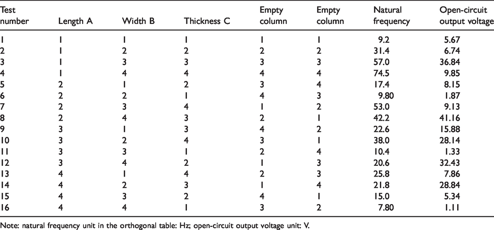
Note: natural frequency unit in the orthogonal table: Hz; open-circuit output voltage unit: V.
Natural frequency range analysis and results.
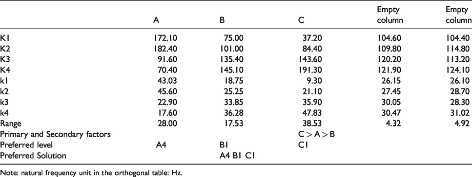
Note: natural frequency unit in the orthogonal table: Hz.
Analysis of output voltage range and results.
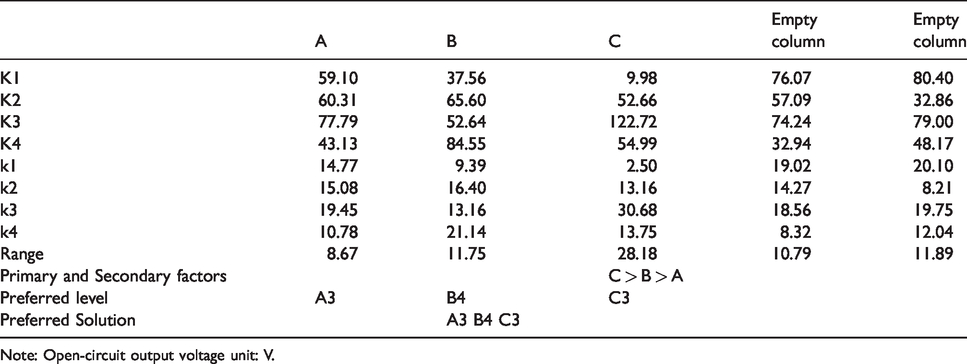
Note: Open-circuit output voltage unit: V.
Modal analysis is carried out on the variable-section circular piezoelectric energy harvesters with different size parameters. According to the range analysis results of natural frequencies in Table 5. It can be seen that natural frequency of the variable-section circular piezoelectric energy harvesters with different size parameters are determined together by different factors (length A, width B, and thickness C). The primary and secondary order of influence of each factor is: C > A > B. It is known from this factor index that vibration natural frequency of the variable-section circular piezoelectric cantilever beam is smallest. The optimal size parameter combination of circular cantilever beam with minimum natural frequency is A4 B1 C1.
The variable-section circular piezoelectric energy harvester with different size parameters is studied, according to the range results analysis of output voltage in Table 6. It can be seen that the length, width and thickness of rectangular cantilever beam (length A, width B, and thickness C) all have an impact on open-circuit output voltage of the piezoelectric energy harvester. The primary and secondary order of influence of each factor on open-circuit output voltage of the variable-section circular piezoelectric cantilever beam is C > B > A. It can be seen that optimal parameter combination of the variable-section circular cantilever beam with maximum open-circuit output voltage is A3 B4 C3.
According to data of the orthogonal experiment table, the modal analysis and piezoelectric analysis results for the variable-section circular piezoelectric energy harvester with different parameters are shown in Figure 6. Figure 6(a) shows natural frequency and open-circuit output voltage in the range of 0–50 Hz. Figure 6(b) shows natural frequency and open-circuit output voltage in the frequency range of 50–100 Hz .
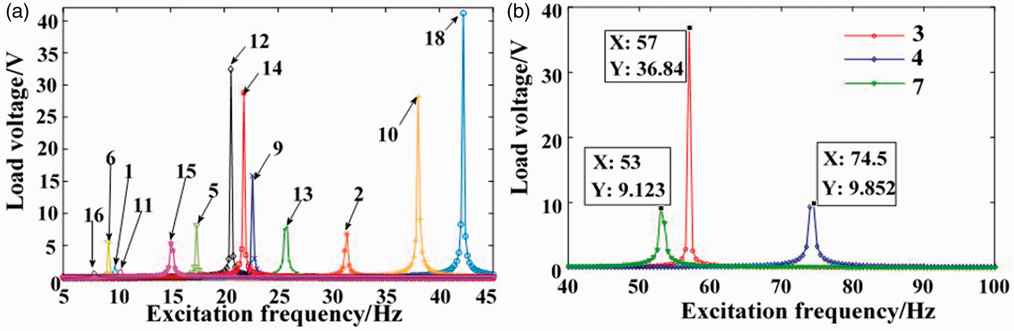
Simulation analysis of a variable cross-section circular piezoelectric cantilever beam: (a) variable section simulation analysis (0–50 Hz) and (b) variable section simulation analysis (50–100 Hz).
In summary, natural frequency of the piezoelectric energy harvester and open-circuit output voltage of the piezoelectric structure are affected by many factors. According to simulation analysis diagram of the variable-section piezoelectric energy harvester and analysis of the orthogonal experiment results, considering fragile nature of piezoelectric ceramic sheet on the variable-section circular piezoelectric energy harvester during vibration, the size (length × width× thickness) of rectangular beam selected by the piezoelectric energy collection is 25 × 20 × 0.2 mm, which meets requirement that the variable-section circular piezoelectric energy harvester can effectively harvest environmental vibration energy in a lower frequency range, and ensure that the piezoelectric ceramic piece can work normally without cracking during vibration energy collection.
Characteristic analysis
The finite element analysis software COMSOL is used to analyze characteristics of the variable-section circular piezoelectric energy harvester. Figure 7 is vibration displacement diagram of the variable-section circular piezoelectric energy harvester. It can be seen from Figure 7 that its vibration is up and down vibration. Under different external excitation vibration accelerations (0.5, 1.0, 1.5, and 2.0 g), the output voltage-frequency curve of the variable-section circular piezoelectric cantilever energy harvester is shown in Figure 8. With amplitude of the external excitation acceleration increasing, output voltage of the piezoelectric energy harvesting device also increases. As shown in Figure 9, adding a mass at the end can effectively reduce natural frequency of the device.
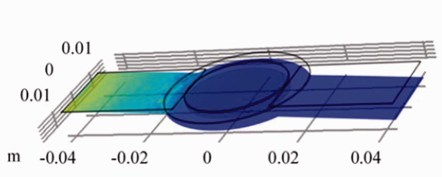
Vibration displacement of circular piezoelectric cantilever beam with variable cross section.
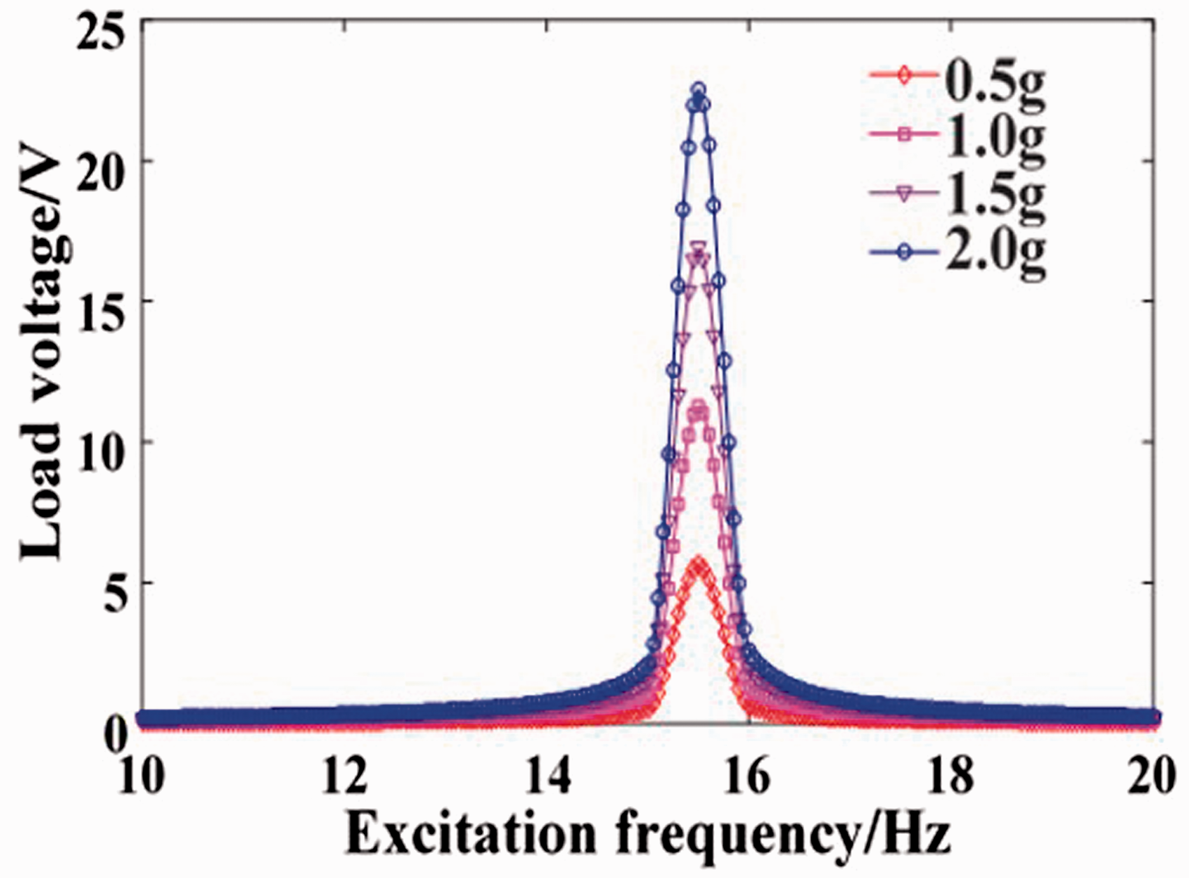
Output voltage-frequency curve for different accelerations.
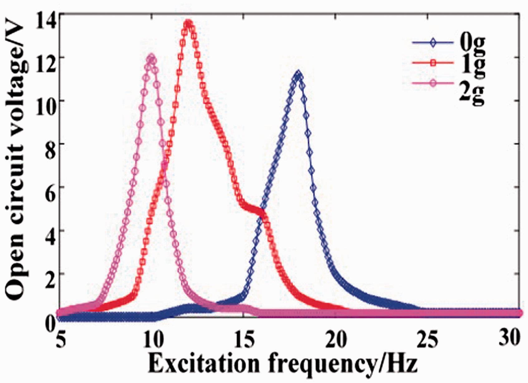
Output voltage-frequency for different masses curve.
The output voltages are compared in Figure 10 between a variable-section circular piezoelectric energy harvester and a classical cantilever beam energy harvester. It can be seen that under same conditions, the variable-section circular piezoelectric cantilever beam not only has a higher output voltage but also lower natural frequency. Therefore, a variable-section circular piezoelectric energy harvester is selected as the low-frequency piezoelectric energy harvesting structure.
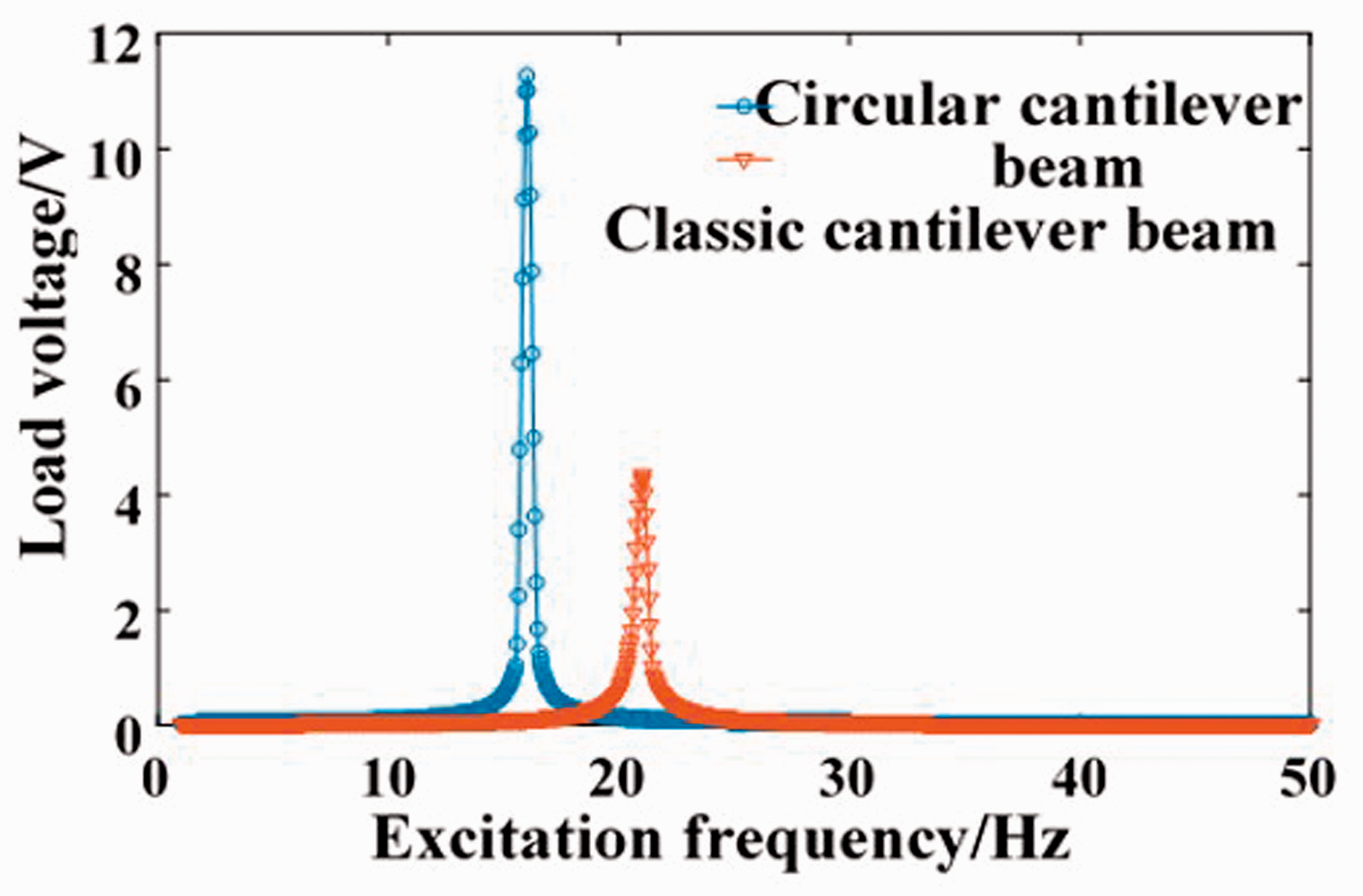
Output voltage comparison chart.
Experimental study
The four kinds of test pieces shown in Figure 11 are designed and numbered. Although the four kinds of test pieces have different resonant frequencies, they can all resonate in the low frequency environment. The rectangular cantilever beam at the end of test piece 1 is not added with mass block, test piece 2 end rectangular cantilever beam, and test piece 3 end rectangular cantilever beam plus two mass blocks, and test piece 4 end rectangular cantilever beam plus four mass blocks. Each mass block used in this article has a mass of 0.6 g, using the principle of magnet attraction, the mass is mounted on upper and lower surfaces of the end of the cantilever beam. Therefore, the number of mass blocks used in this paper is even.
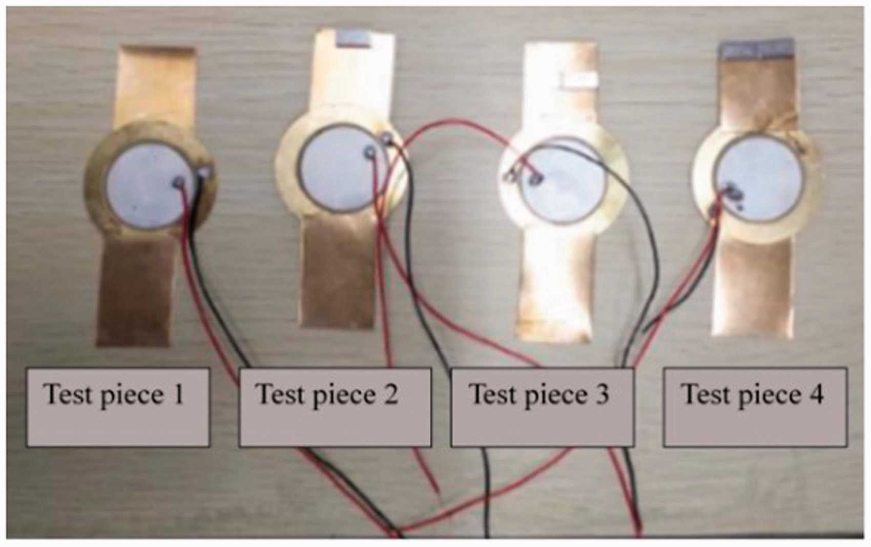
Physical diagram.
The above four structures are arranged in an array structure and installed on experimental platform. The structure is experimentally studied and the power generation performance of piezoelectric energy harvester is tested in the low frequency range. Figure 12 shows device of the variable-section circular piezoelectric energy harvester, and Figure 13 shows experimental test platform of the piezoelectric energy harvesting device.
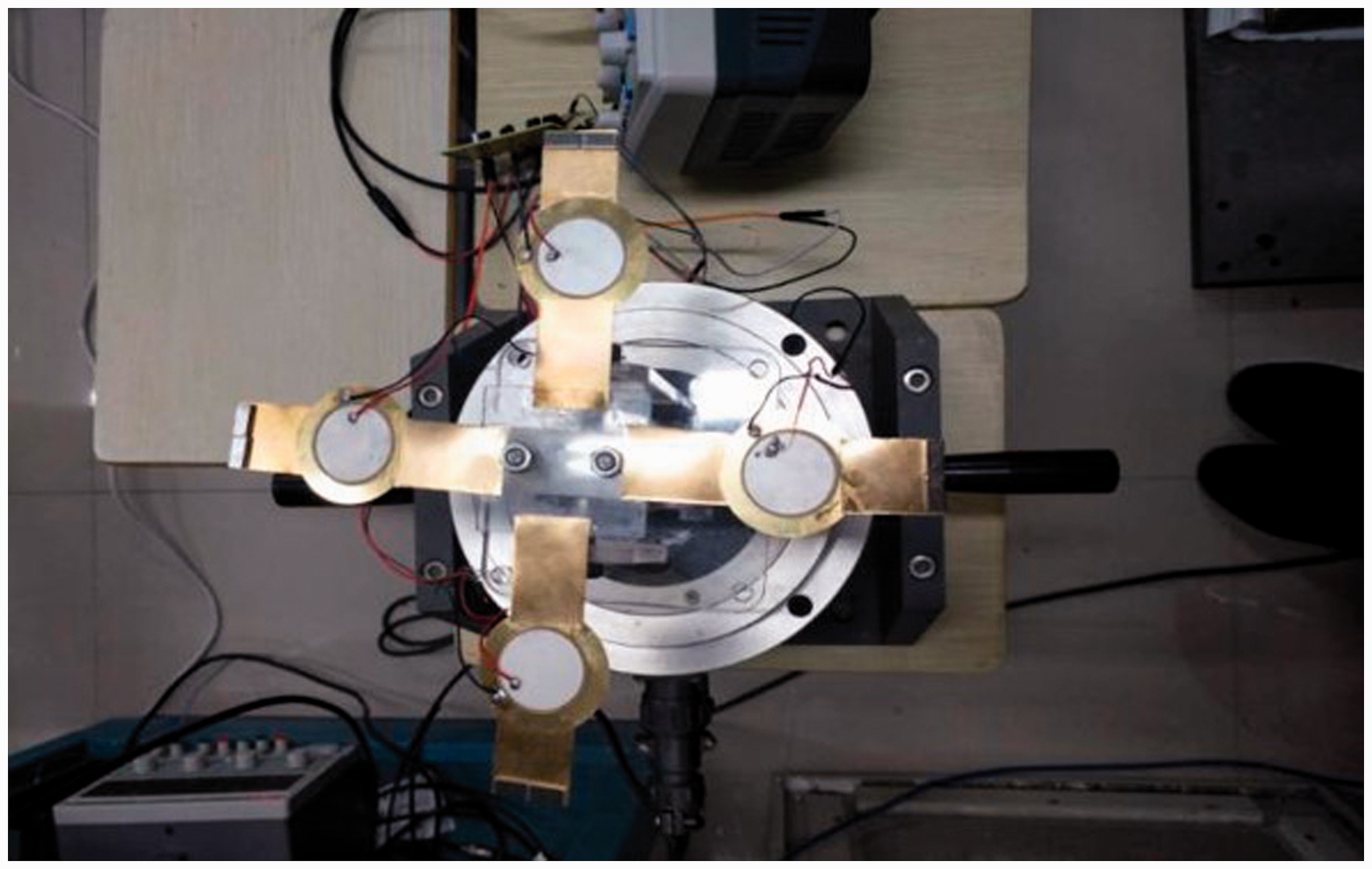
Variable section piezoelectric cantilever beam collecting device.
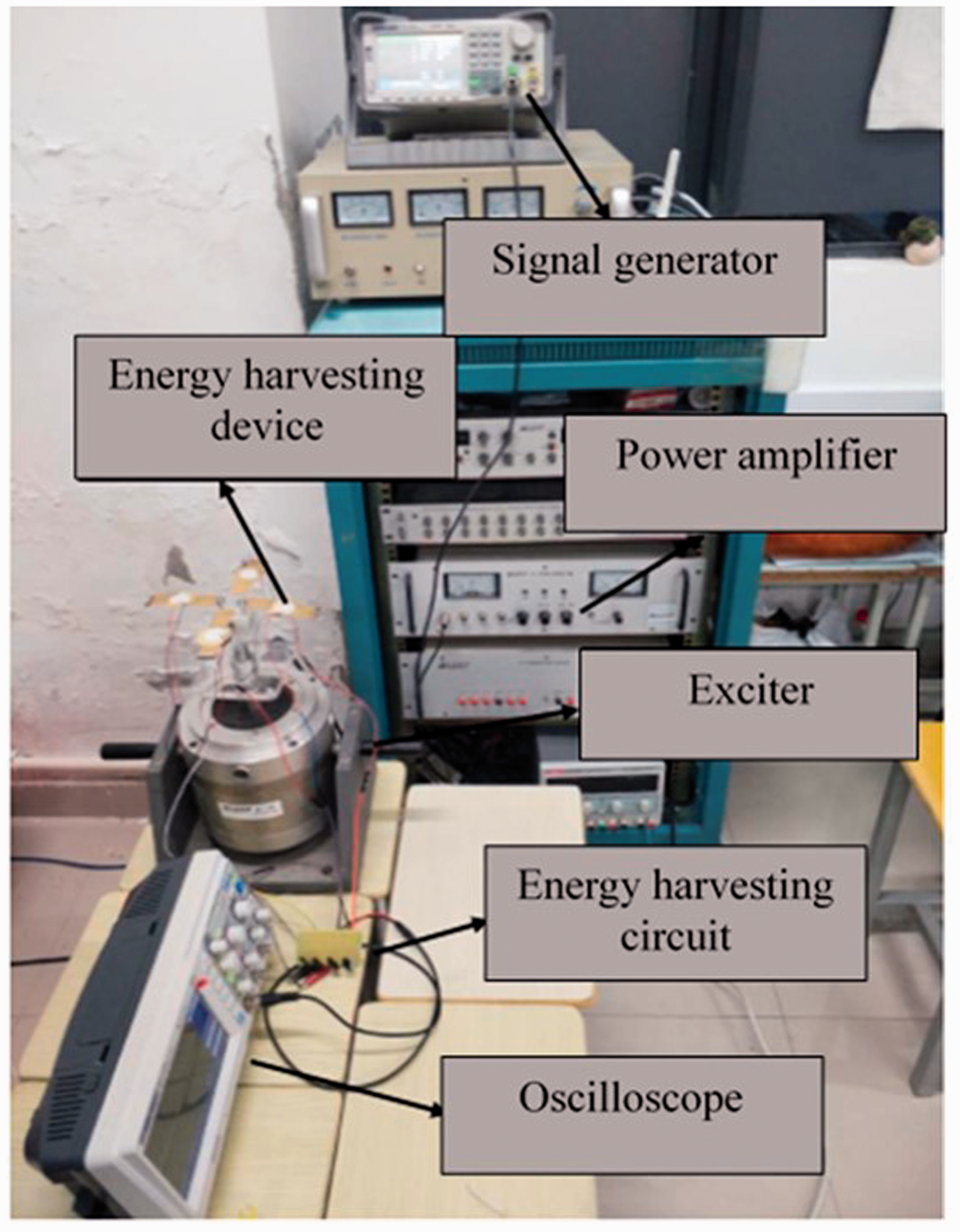
Piezoelectric energy harvesting device experimental test platform.
According to the previous analysis of characteristics of the variable-section circular piezoelectric energy harvester, the natural frequency of the variable-section circular piezoelectric energy harvester is in the range of 10–20 Hz when the mass block is 0–2 g. Therefore, in order to study power generation performance of the circular piezoelectric energy harvester with variable cross-section, the frequency sweep experiment is carried out in the range of 5–30 Hz.
Figure 14 shows the experimental results of series and parallel rectified output voltages for different numbers of arrays. As shown in Figure 14(a), with the number of arrays increasing, the output voltage will increase, but the natural frequency of the piezoelectric energy harvester remains unchanged. When the number of arrays is increased from one to four, and connected in series through rectifying circuits, corresponding maximum open-circuit output voltages are 6.00, 8.42, 9.80, and 11.34 V, respectively. As shown in Figure 14(b), the change of array number will not change open-circuit output voltage on piezoelectric patch. The open-circuit output voltage on piezoelectric patch is 6.00 V, and natural frequency of the piezoelectric energy harvester will not change.
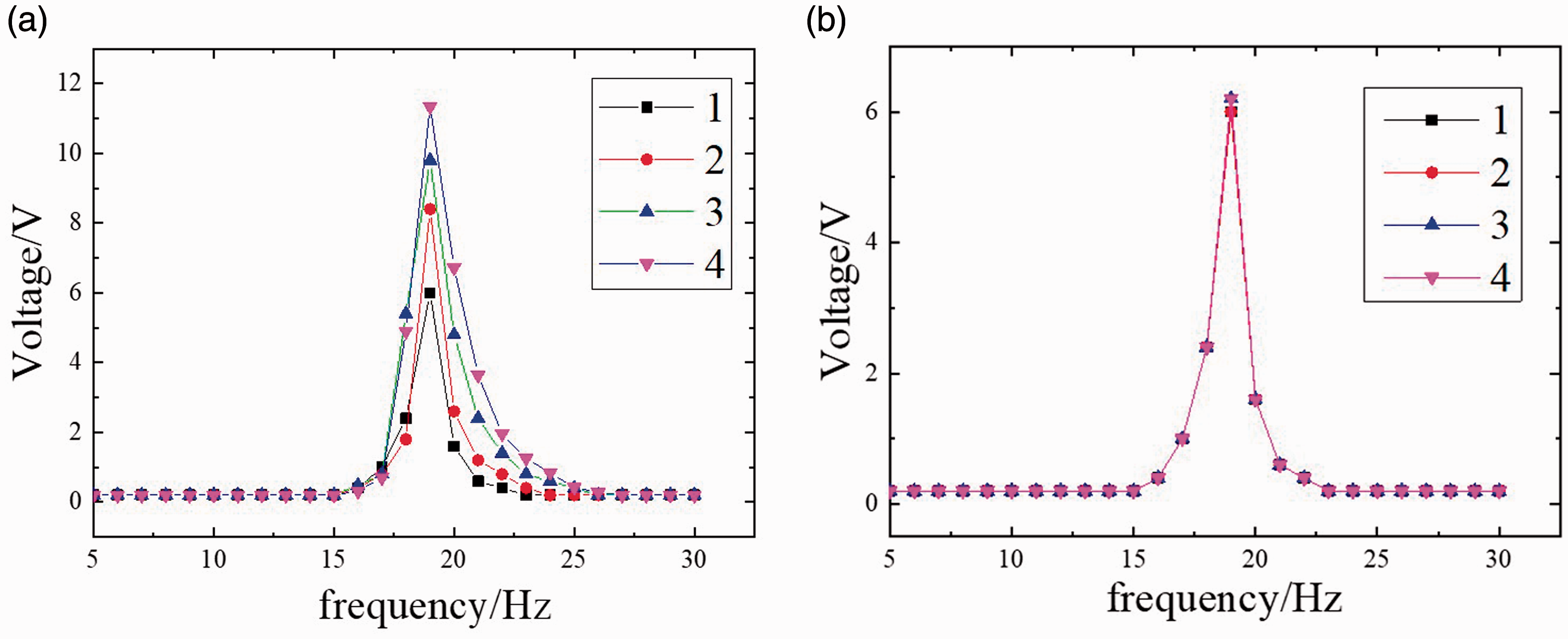
Variable section piezoelectric cantilever beam different array number output voltage: (a) different array number series rectified output voltage and (b) parallel rectified output voltage with different array numbers.
Figure 15 shows the experimental results of series and parallel rectified output voltages of different mass blocks. It can be seen from Figure 15(a) that as the number of mass block increases, the natural frequency of the piezoelectric energy harvester gradually decreases. When number of mass blocks is 0, 2, and 4, respectively, the corresponding natural frequencies are 19, 13, and 10 Hz, respectively, the maximum open-circuit output voltage is 11.34, 11.62, and 18.2 V, respectively. It can be seen from Figure 15(b) that as number of mass blocks increases, the natural frequency of the piezoelectric energy harvester decreases, and output voltage remains substantially unchanged. When number of mass blocks is 0, 2, and 4, respectively, the corresponding natural frequency are 19, 13, and 10 Hz, respectively, the maximum open-circuit output voltages are 6.2, 6.62, and 6.20 V, respectively.
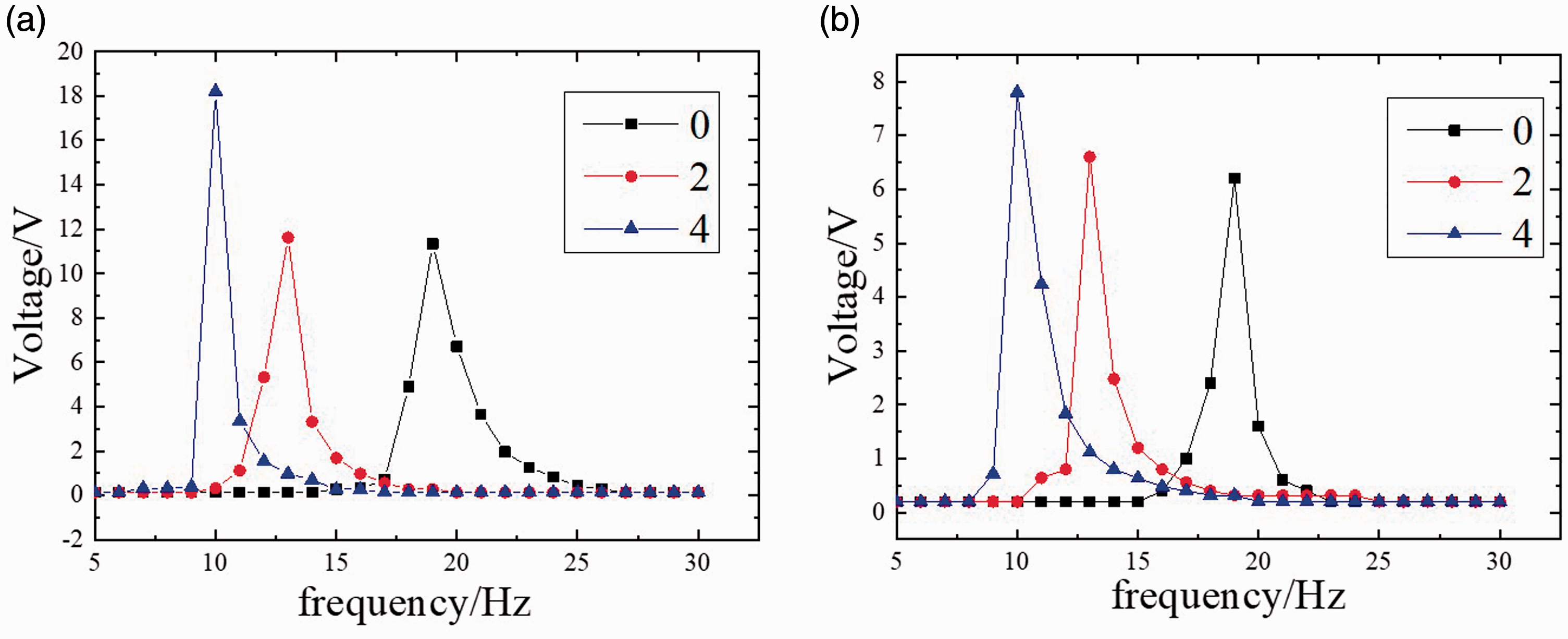
Variable cross-section piezoelectric cantilever beam output voltage of different masses: (a) series rectified output voltage of different masses and (b) parallel rectified output voltage different masses.
Four variable-section circular piezoelectric energy harvesters are connected together in series through a rectifier circuit to test output power of the variable-section circular piezoelectric energy harvester, Figure 16 shows the rectified output power under different loads. According to Figure 16(a), when four variable-section circular piezoelectric energy harvesters are connected in series, different load resistances correspond to different output powers under the standard energy interface circuit. When the optimal resistance is 150 KΩ, maximum output power of the variable-section circular piezoelectric energy harvester is 52 µW. According to Figure 16(b), when four circular piezoelectric energy harvesters with variable section are connected in parallel, different load resistances correspond to different output powers under the standard energy interface circuit. When optimal resistance is 180 KΩ, maximum output power of the variable-section circular piezoelectric energy harvester is 89 µW.
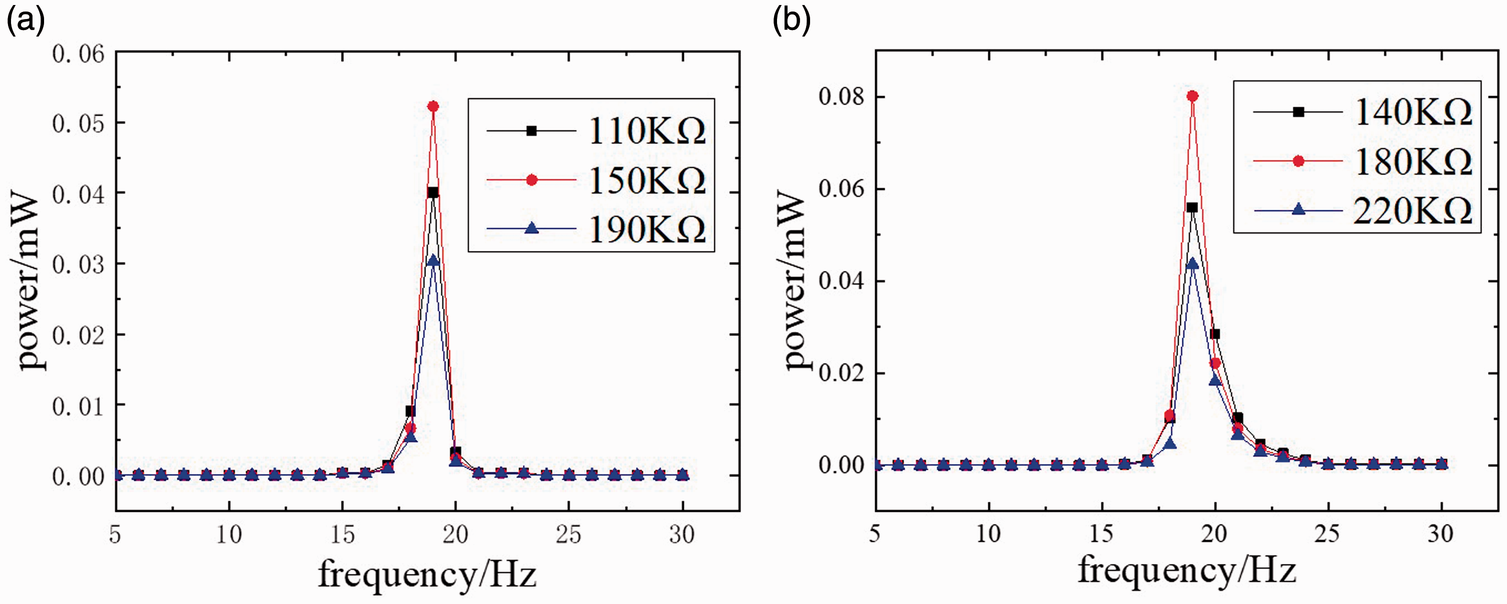
Different load rectified output power: (a) series rectified output power of different loads and (b) parallel rectified output power of different loads.
Four variable-section circular piezoelectric energy harvesters are connected together in parallel through a rectifier circuit to test output power of the variable-section circular piezoelectric energy harvester. Figure 17 shows the rectified output power when different numbers of masses (0, 2, and 4) are installed at the end of a variable-section circular piezoelectric energy harvester. Figure 17(a) shows that four variable-section circular piezoelectric energy harvesters are connected in series. Under the standard energy interface circuit, different numbers of mass blocks are installed at the end of the energy harvester, and output power is different. When optimal resistance is 150 KΩ, and the number of end mass blocks is 0, 2, and 4 respectively, the corresponding output powers are 52, 77, and 82 µW, respectively. Figure 17(b) shows that four variable-section circular piezoelectric energy harvesters are connected in parallel. Under the standard energy interface circuit, different numbers of mass blocks are installed at the end of the energy harvester, and output power is different. When optimal resistance is 180 KΩ, and the number of end mass blocks is 0, 2, and 4 respectively, the corresponding output powers are 89, 150, and 213 µW, respectively.
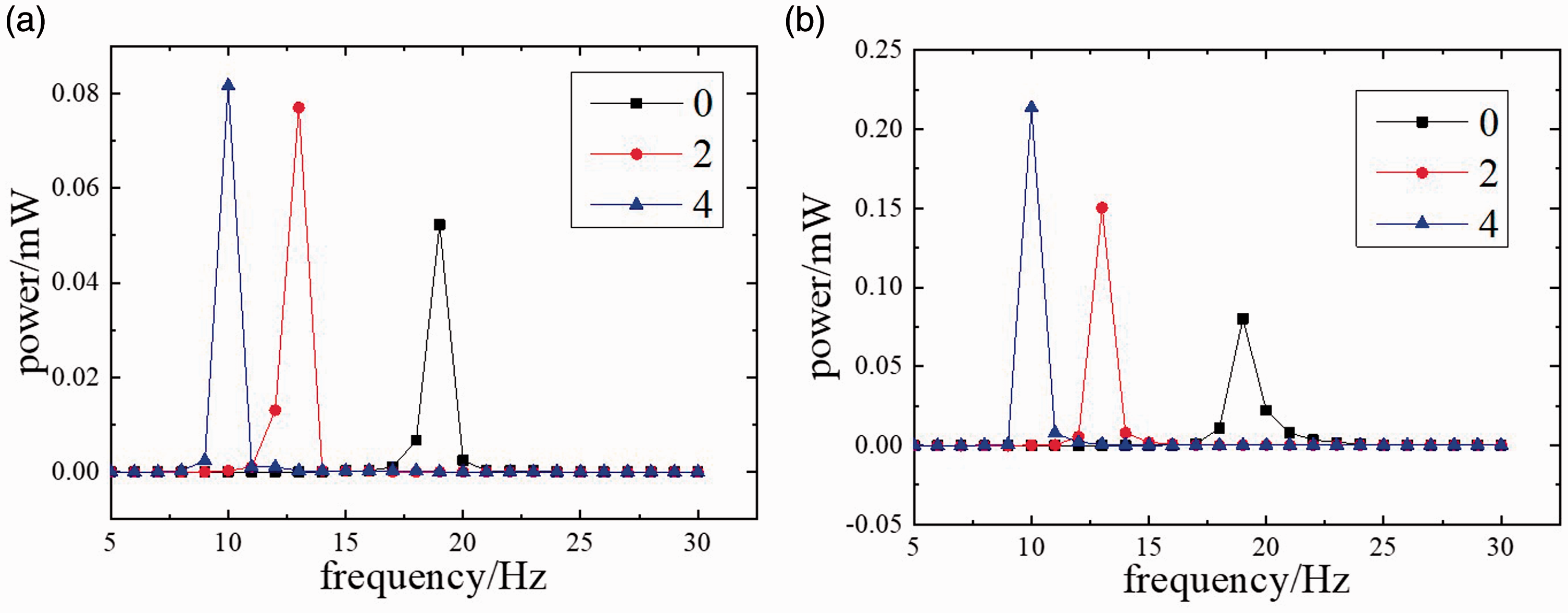
Rectified output power of different masses: (a) parallel rectified output power of different masses and (b) different mass block series rectified output power.
Therefore, the variable-section circular piezoelectric energy harvester has a large output power and good harvesting performance. Table 7 shows that the maximum output power and the optimal resistance value at each resonance frequency point.
Output power and optimal load.
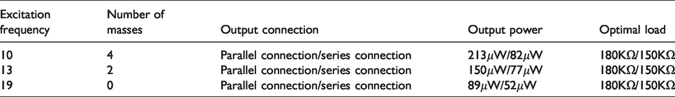
In summary, the maximum power can be output only when the impedance of the piezoelectric device matches the external resistance. At the same time, the output power of the variable cross-section circular low-frequency piezoelectric vibration energy harvester in parallel is larger than that in series. The maximum output power of four array structures connected in parallel at the resonance frequency point of 10 Hz and external load of 180 KΩ is 0.213 mW, which can meet requirements of power supply for micro power devices.
Conclusion
In this paper, a variable-section circular piezoelectric vibration energy harvester structure is proposed, and the modal analysis and piezoelectric analysis of piezoelectric vibrators with the same area and different shapes are carried out. According to the analysis results, the variable-section circular piezoelectric cantilever beam is selected as harvesting structure of energy harvesting device. The structure parameters of piezoelectric vibration energy harvester are optimized by orthogonal experiment. The energy harvesting effect of variable-section circular piezoelectric vibration energy harvester is analyzed by simulation and experiment. The experimental platform is built to test output voltage and output power of variable-section circular piezoelectric vibration energy harvesting device. The experimental results show that when the number of energy harvester is 4 and the external load is 180 KΩ, the parallel output power can reach 0.213 mW. Energy harvesting effect of variable-section circular piezoelectric vibration energy harvester is verified.
Footnotes
Declaration of conflicting interests
The author(s) declared no potential conflicts of interest with respect to the research, authorship and/or publication of this article.
Funding
The author(s) disclosed receipt of the following financial support for the research, authorship, and/or publication of this article: This work is supported by National Natural Science Foundation of China (51305003), Anhui Postdoctoral Science Foundation (2017B172), and Anhui University of Science and Technology National Natural Science Foundation Pre-research Project (2016yz004).