
Abstract
Based on the liquid suspension three-degree-of-freedom motor, the three-degree-of-freedom dynamic model of spherical bearing is established. The spatial distribution of the radial electromagnetic force is calculated. The results show that the second harmonic has the greatest influence on the motor vibration. At the same time, considering the roughness of rotor surface, the pressure distribution and film thickness distribution of oil film are calculated by the finite difference method. Through the finite element method, the force of the stator spherical shell and the rotor is analyzed when the rotor slips. Moreover, the oil film modal is calculated and it is found that the forward precession is stronger when the oil film whirls. Finally, the experimental platform is built. The vibration amplitude of the spherical bearing under the condition of normal operation and oil whirl was measured. By comparing the relationship between vibration amplitude and vibration frequency, it is found that oil whirl causes negative vibration growth of spherical bearing, which leads to dry friction between rotor and stator. It provides a good theoretical basis for the practical application and further optimization design of spherical bearing.
Introduction
Liquid suspension three-degree-of-freedom ball motor is a mechanical system with three degrees of freedom.1,2 It is widely used in aerospace vehicles, electric gyroscopes, bionic vision systems, mixers and other important directions with high control accuracy and excellent dynamic performance. With the rapid development of science and technology, three-degree-of-freedom motor is developing towards high speed and heavy load. For the stability and reliability of the spherical bearing system which plays the role of support and lubrication, a higher level is required. The liquid suspension three-degree-of-freedom motor combines the electromagnetic part with the spherical bearing part. The unique structure of spherical bearing makes it have good radial bearing capacity and certain axial bearing capacity, with strong stability. Spherical bearing is an important part of the motor to achieve rotation and support. Even in the process of using precision machinery manufacturing, wear, depression, peeling 3 and other phenomena may have an irreversible impact on the dynamic characteristics of the spherical bearing. Therefore, the most important thing is to improve the bearing capacity of spherical bearing and reduce the vibration caused by the change of contact stiffness of rotor and stator with time. 4
For liquid suspension three-degree-of-freedom spherical motor, the causes of motor vibration can be divided into mechanical vibration and electromagnetic vibration. Electromagnetic vibration is caused by the radial electromagnetic harmonic force after the motor is energized.5,6 Mechanical vibration is caused by the friction and torque acting on the contact point between the rotor spherical shell and the stator spherical shell, which will seriously affect the rotation performance of the motor.
However, the surface roughness of bearing has an important influence on the vibration caused by friction and surface stress. In the traditional bearing analysis, the default bearing lubrication surface is rigid and smooth, so it is not suitable for the research with high accuracy. The inner and outer rings of spherical bearings are spherical, so the surface roughness of the bearing cannot be ignored in the calculation, so as to ensure that the theoretical analysis is consistent with the actual situation.
At the same time, the complex changes of the stability characteristics of the spherical bearing oil film directly affect the motion state of the equipment. Many scholars use different models to analyze the oil film forces of different types of bearings. 7 When calculating the nonlinear oil film force of bearing, French scholar Machdao 8 proposed to simulate the nonlinear oil film force by studying the short cylindrical bearing. This paper will also use this method to analyze the spherical bearing. However, the setting of boundary conditions is different. When many people analyze the characteristics of bearing oil film pressure, they assume that the bearing boundary is free boundary by default. 9 However, for spherical bearings, the oil film force should be obtained by dividing the oil film pressure along the ball area. Thus, it can reflect the action of nonlinear oil film force.
In Lin et al. 10 and Aditya et al., 11 the factors of bearing failure caused by vibration of spherical bearing are described, and the influence of surface roughness of parts on bearing life is analyzed. Due to long-term operation, the bearing deformation caused by fluid pressure is different. Therefore, it is necessary to study the fluid structure coupling analysis12,13 and the whirl phenomenon of the spherical bearing oil film. Based on the physical model of rotor bearing vibration system,14–17 with the improvement of bearing product quality, the limitations of classical spherical bearing vibration theory in bearing product quality requirements are reflected. In other words, the factors of friction theory of lubricating oil are considered. In the work of spherical bearing, the dry contact between stator and rotor becomes one of the main sources of noise and vibration. The oil film of spherical bearing also has a very important influence on its vibration and noise characteristics.
In this paper, spherical bearing is taken as the research object. The structure plays the role of rotation and support in the three-degree-of-freedom motor structure of liquid suspension. The failure probability of rotating machinery is as high as 40%. 18 Of course, even in short-term operation, in case of cavitation effect or oil film rupture, it will also cause dry contact between the stator and rotor of spherical bearing, resulting in serious wear, stagnation and increased failure of bearing. The research shows that the failure of 19 fit clearance will cause the impact and friction between the bearing and the bearing seat, which will cause strong nonlinear vibration of the rolling bearing and the whole rotor system. Therefore, the vibration modal analysis of the spherical bearing oil film is of great significance.
This paper mainly analyzes the reason leading to the vibration of spherical bearings. It includes the harmonic analysis of radial electromagnetic force, the wear of bearing structure caused by rotor slip, and the influence of oil whirl on rotor speed and vibration. Finally, an experimental platform is built to verify and analyze the feasibility of the spherical bearing. It is the theoretical basis for further optimization of bearing lubrication performance.
The structure of motor
The structure of the three-degree-of-freedom spherical motor in liquid suspension is shown in Figure 1. The motor is composed of an electromagnetic part and a supporting structure. The electromagnetic structure of the motor is composed of a quadrupole ring main permanent magnet located at the equator of the spherical motor and a claw distribution coil winding at the corresponding position. At the same time, the bottom permanent magnet and coil winding realize the fine tuning of the motor rotation precision.1,2 At the same time, the bottom permanent magnet and the coil winding work together to realize the fine adjustment of the motor rotation accuracy. These components form a spherical bearing. Finally, by formulating the electrification strategy, the main and secondary permanent magnets of the motor can be coordinated with the spherical bearing structure, so that the three-degree-of-freedom motor can achieve a large range of motion and a small range of fine-tuning multi-degree-of-freedom motion.
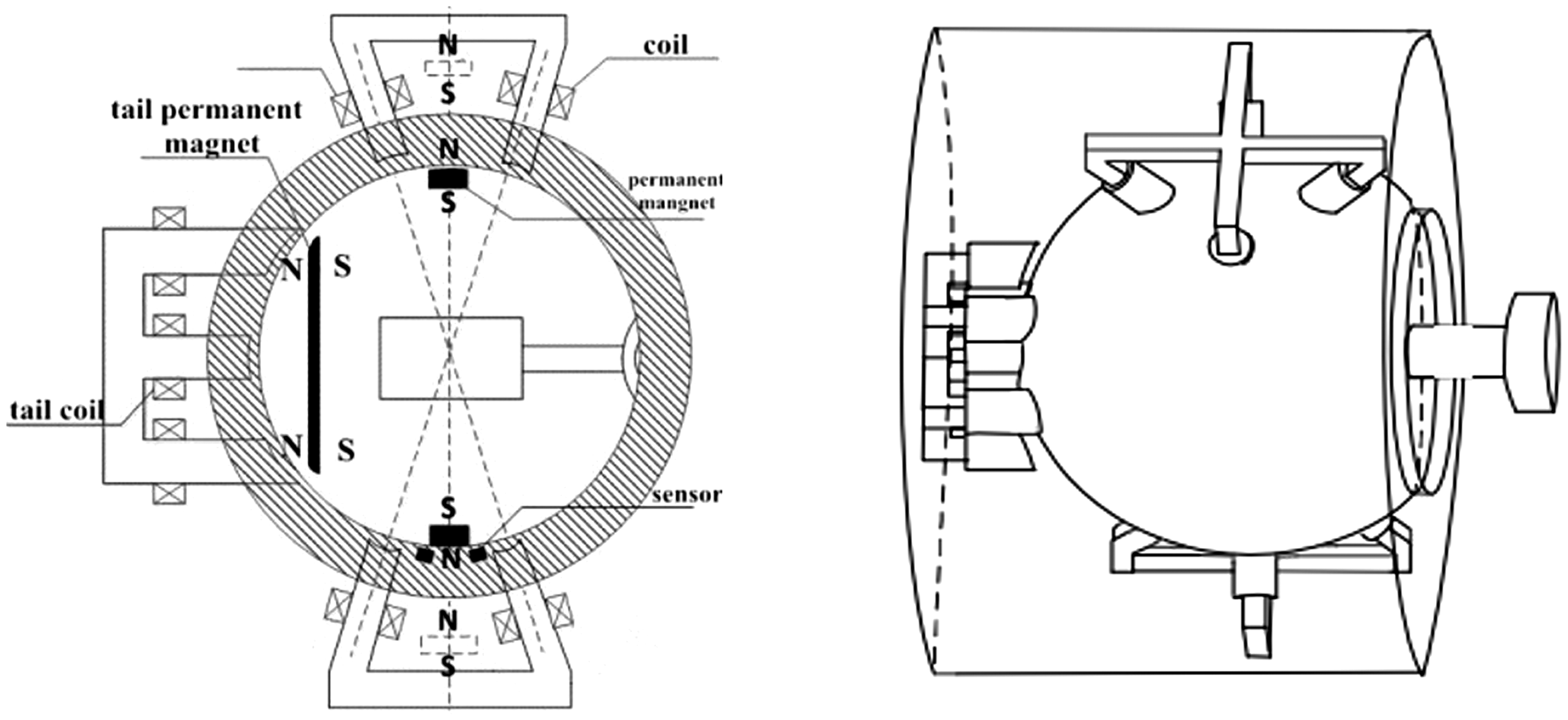
Model diagram of motor.
When the motor is working, the radial electromagnetic force drives the inner rotor to rotate, and the rotor rotates to drive the lubricating fluid to form a continuous oil film, so that the rotor is suspended between the stator and rotor to form a convergent wedge gap. The rotating rotor brings the lubricating oil continuously into the wedge gap to form a pressure support, balancing the external load, and the suspended rotor and stator housing are completely separated by the lubricant. In this process, mechanical friction is transformed into liquid friction.
The working principle of spherical bearing is based on the bearing mechanism of oil wedge. At the same time, the lubricant is squeezed to produce a supporting force on the rotor. Thus, the lubrication film of spherical bearing is formed.
Analysis of radial electromagnetic force
When the motor is working, the coil winding is connected with current. The magnetic field produced by the permanent magnet and the current in the coil interact to produce electromagnetic force. The electromagnetic force can be divided into radial electromagnetic force and axial electromagnetic force. The harmonic of radial electromagnetic force 20 is the main cause of electromagnetic vibration. Firstly, the magnetic field produced by permanent magnet is calculated and analyzed.
Considering the special form of the motor winding, the calculation method of three-dimensional magnetic field should be adopted, and different boundary conditions should be set to calculate the flux density distribution. The three-dimensional magnetic field of the winding can be described by equation (1)
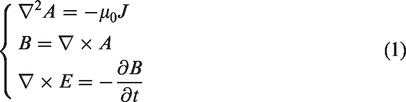
Through the method of separating variables, the magnetic induction intensity can be described by the equation group (2)
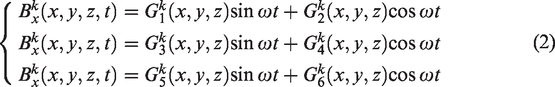
The distribution trend of flux density of permanent magnet along the equator is shown in Figure 2.
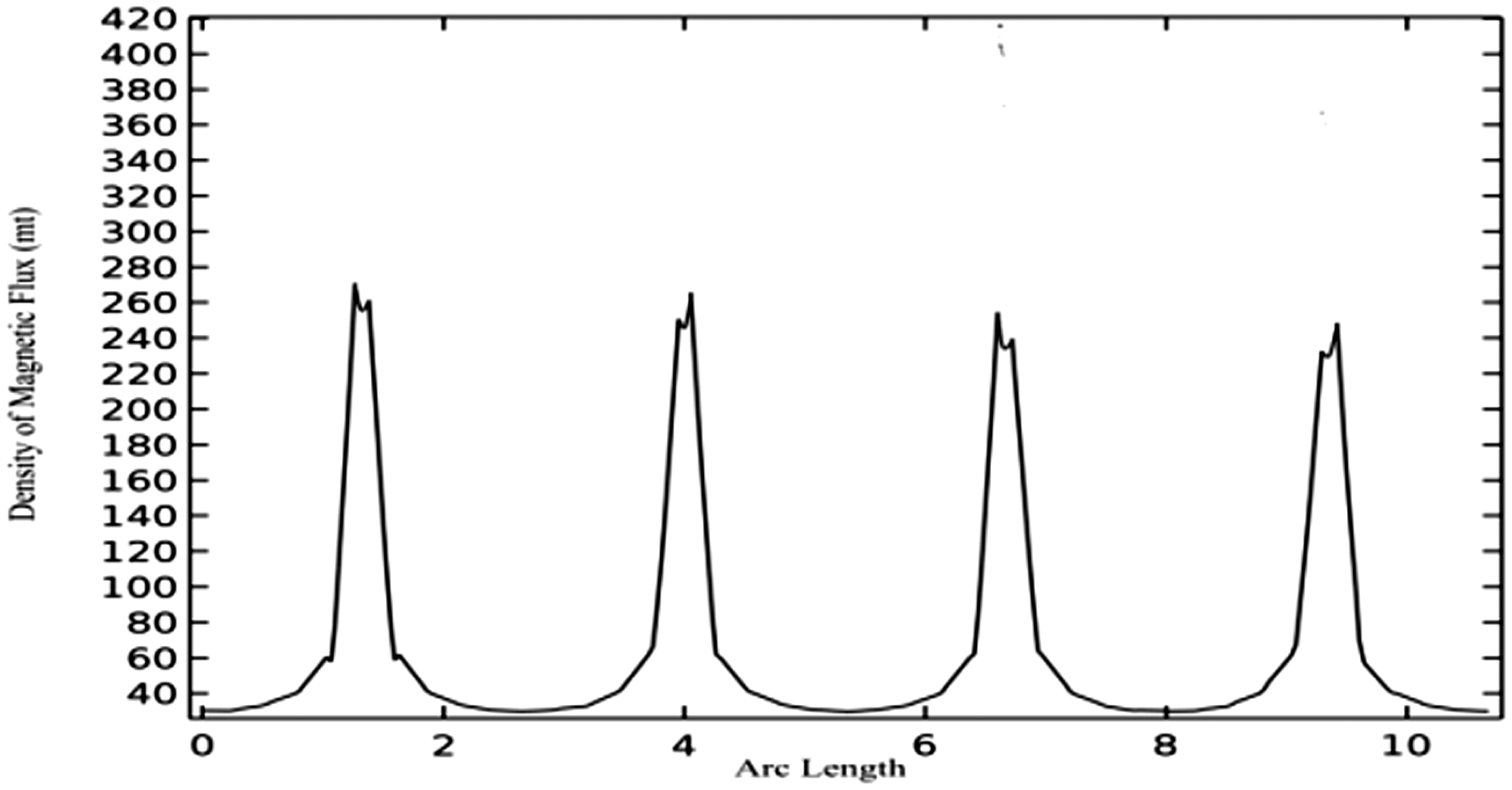
Density of magnetic flux.
The air gap magnetic field is composed of the magnetic field produced by permanent magnet and the armature magnetic field produced by the winding after power on. Therefore, the air gap magnetic field changes with time and space. According to the calculation results, the magnetic field intensity presents periodic distribution. At the air gap, the magnetic field intensity is the largest, but also fluctuates here.
Under the action of air gap magnetic field, the radial electromagnetic force wave generated by the electrified coil is expressed as equation (3)
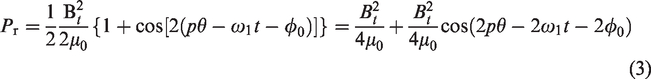
Equation (3) describes the relationship between the distribution of the radial electromagnetic force and the mechanical angle in the spatial rotation coordinate system. The three-dimensional distribution of the calculated radial electromagnetic force is shown in Figure 3.
Radial electromagnetic force distribution.
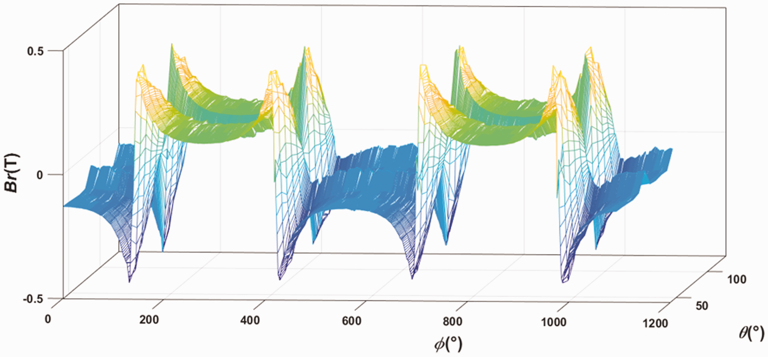
At the same time, in order to study the influence of each harmonic of the radial electromagnetic force on the vibration of the motor at different spatial mechanical angles and frequencies, the radial electromagnetic traveling wave force is decomposed along the mechanical angle (PHI), and the 1–7 order harmonic sequence decomposition diagram of the radial electromagnetic force in Figure 4 is obtained. The even harmonics of the pole pair have a great influence on the first mode shape of the radial electromagnetic force. The number of poles of the liquid suspension spherical motor is 2. The first four modes have great influence on the motor, and the second harmonic has the greatest influence on the motor.
The harmonic decomposition of radial electromagnetic force. (a) 1–3 order harmonics (b) 4–7 order harmonics.
Vibration analysis of spherical bearing
Elastohydrodynamic lubrication model of spherical bearing
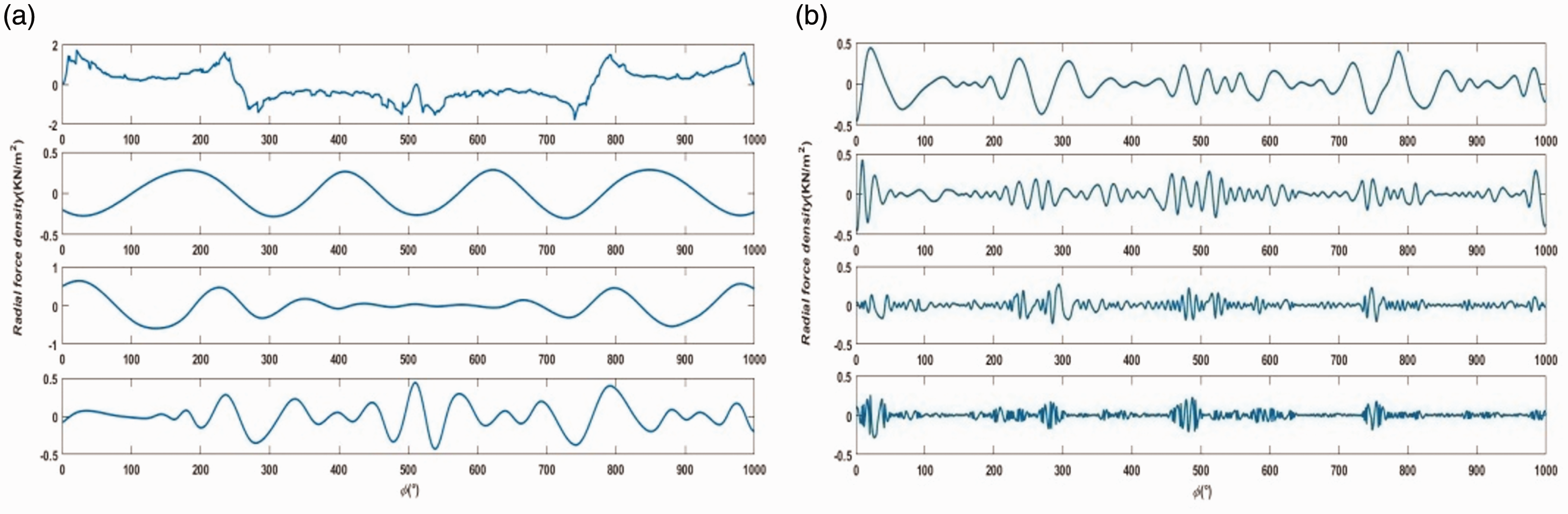
The supporting structure of spherical motor has the structural characteristics of spherical bearing. And it combines the basic laws of fluid flow, such as mass conservation law, energy conservation law and momentum conservation law (N-S equation). The combination of lubrication theory and elastic contact theory is fluid structure coupling. The relative motion of the stator and rotor surface drives the lubricating fluid to form pressure support and balance the external load. The suspended rotor and stator are completely separated by lubricant. Liquid friction is formed, as shown in Figure 5.
Bearing eccentricity section.
The governing equation of viscous incompressible fluid is expressed by continuity equation (4)
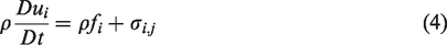
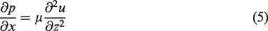
Because the fluid involved in this study is viscous and incompressible, the density is constant. At the same time, ignoring the effect of gravity on oil film, the N-S equation is as follows
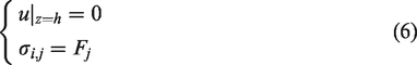
The coupling boundary conditions of fluid and rotor surface are as follows
The calculation method of the film equation in He and Sun
21
and He
22
is adopted. Multiply the control equation and boundary condition by
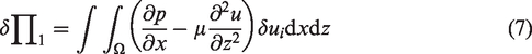
After simplification, we get
According to the principle of division, let

The form of constructing the solution satisfying the boundary condition is as follows

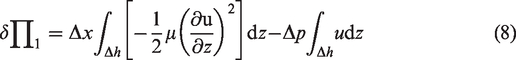
After calculating the integral, the formula (11) is obtained

After the elimination of
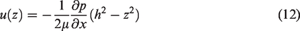
If the influence of oil film thickness is ignored, the oil film pressure distribution shows a quadratic function trend in the same X coordinate.
The disturbance of rough surface and the harmonic of radial electromagnetic force are the causes of nonlinear elastic deformation between stator and rotor when the spherical bearing is working under load. The equivalent stiffness of the oil film between the stator and rotor is an important feature in the study of the vibration characteristics of the spherical bearing. The stiffness of the lubricating oil film of the bearing is determined by the minimum film thickness when the temperature effect on the viscosity of the lubricating oil is ignored.
23
The oil film thickness equation considering the elastic deformation and roughness of the rotor is given as

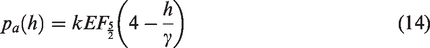
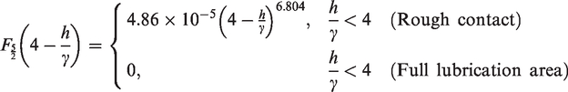
The surface roughness of rotor lubrication is approximately the Gauss distribution. When dry friction contact occurs between the stator and rotor, the relation equation between the roughness and contact pressure is
Due to the small diameter of the oil film between the inner and outer rings (relative to the diameter of the circular section), the lubricant has a certain viscosity, and the Reynolds number of the clearance oil film flow is small, which generally belongs to the laminar flow range. According to the fluid structure coupling theory and model characteristics, the boundary conditions are set as follows:
Solid boundary condition: the end face of spherical bearing is free, the outer ring is set as fixed constraint, and the interface between the inner wall of the outer ring and lubricant is fluid solid coupling boundary. Fluid boundary condition: under the lubrication condition, the contact surface between the lubricating oil and the outer wall of the inner ring is set as the antiskid wall, and the friction between the inner ring and the outer ring is reduced through the fluid structure coupling boundary. Fluid hypothesis: the studied and experimental fluid is incompressible Newtonian fluid, and the lubricating film is very thin, so the viscous motion of the fluid in the gap is dominant, so the mass of the fluid is ignored. Compared with the viscous force of lubricating medium, the inertial force and centrifugal force of oil film bending are ignored.
The pressure and thickness distribution of lubricating oil film are calculated by programming software with the difference method, as shown in Figure 6. Among them, (a) and (b) are oil film pressure distribution and oil film thickness distribution with smooth rotor surface. (c) and (d) are the calculation results considering the surface roughness of rotor. The rigidity of lubricating oil film can directly reflect the bearing capacity of spherical motor. With the increase of roughness amplitude, the oil film stiffness presents the nonlinear change. The maximum value of the oil film stiffness is near the center of the contact area, the oil film thickness distribution is not uniform, and the fracture will seriously affect the stability of the spherical motor. The bearing capacity of spherical motor is reflected by the oil film pressure. The bearing capacity of the motor is directly proportional to the oil film pressure. When the oil film pressure reaches a stable state, it appears as elastohydrodynamic lubrication. When the lubricating oil film pressure is too high, the oil film will break. At this time, it is easy to make the stator and rotor of the motor contact directly, resulting in the friction and wear of the bearing. Therefore, the continuity of the pressure oil film formed during the operation of the motor is very important.
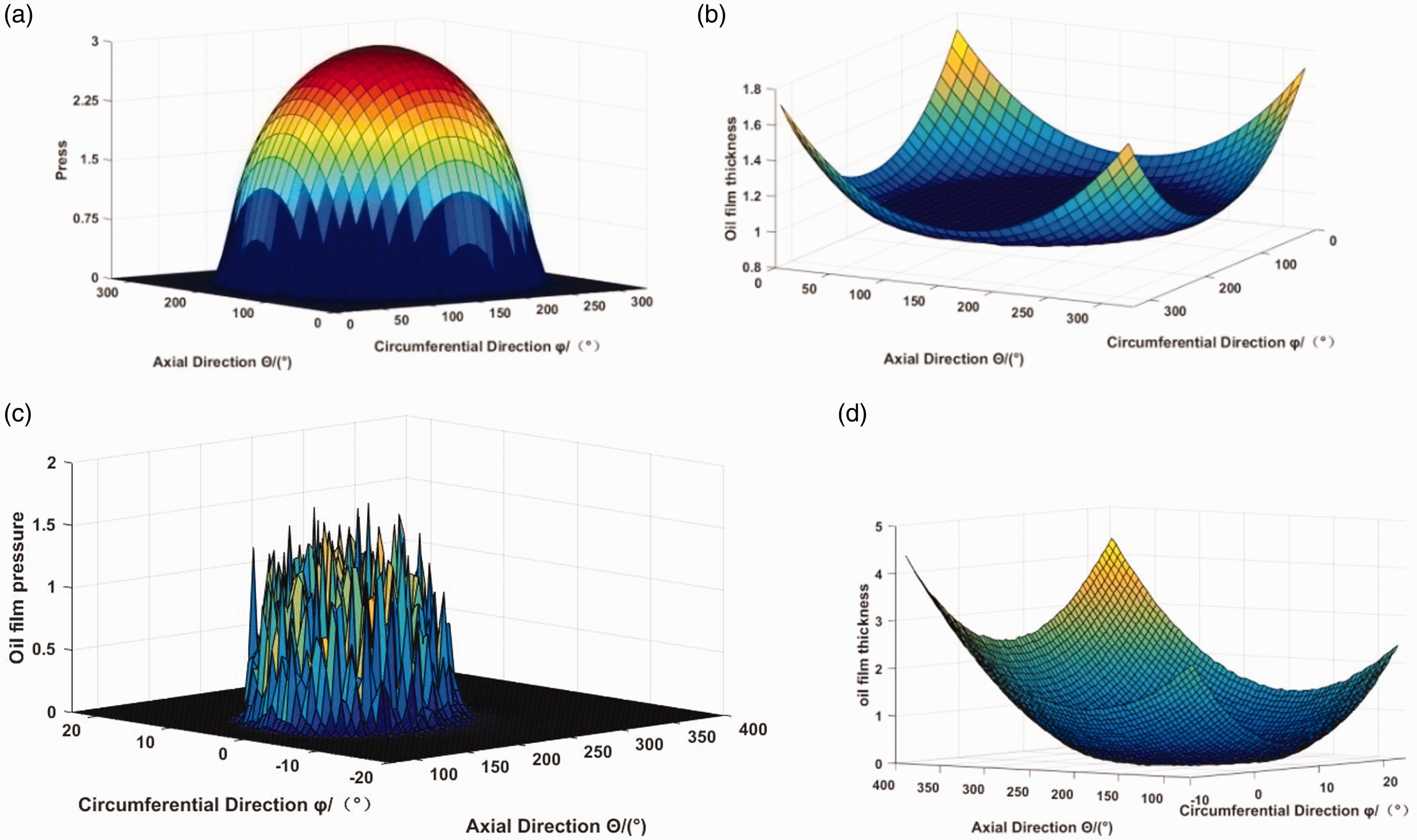
Film pressure and film thickness distribution. (a) Pressure distribution of oil film on smooth surface. (b) Thickness distribution of oil film on smooth surface. (c) Pressure distribution of oil film on rough surface. (d) Thickness distribution of oil film on rough surface.
Modal analysis
The disturbance of random rough surface of spherical bearing cannot be ignored. Through the generalized three-degree-of-freedom coupling vibration model
23
applicable to three-degree-of-freedom motor, the vibration model of spherical bearing under combined radial and axial moment load is simplified as shown in Figure 7. In the figure, m1 and m2 respectively represent the rotor and stator mass, k1, k2 and k3 respectively represent the horizontal, inclined and vertical stiffness, c1, c2 and c3 respectively represent the horizontal, inclined and vertical damping coefficients, kc represents the contact stiffness coefficient of stator and rotor, Ff represents the corresponding friction force, N represents the normal bearing force of spherical bearing, v and
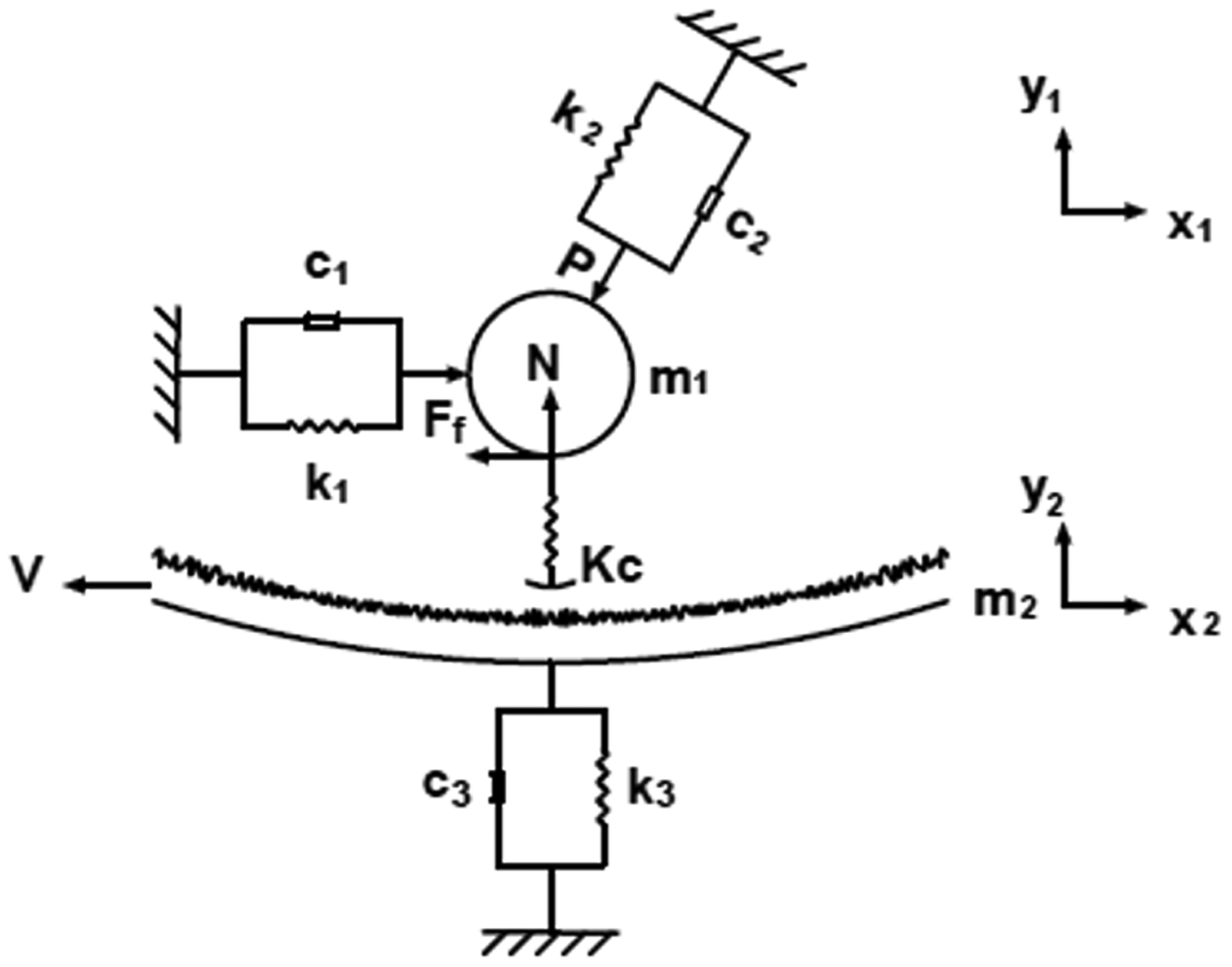
Elastohydrodynamic contact vibration model of spherical bearing.
The vibration equation of the system can be expressed as

In order to observe the stiffness and tension of lubricating oil film conveniently, a three-dimensional finite element simulation model of oil film is established. Through the annular membrane supported by the inner and outer edges, the in-plane direction is constrained to avoid rigid body motion. In the calculation and analysis, the radial electromagnetic force is introduced as the prestress of the rotor boundary, and the spring foundation in three directions is added to calculate the modal shape of the oil film. The results are shown in Figure 8, which are the first six modals.
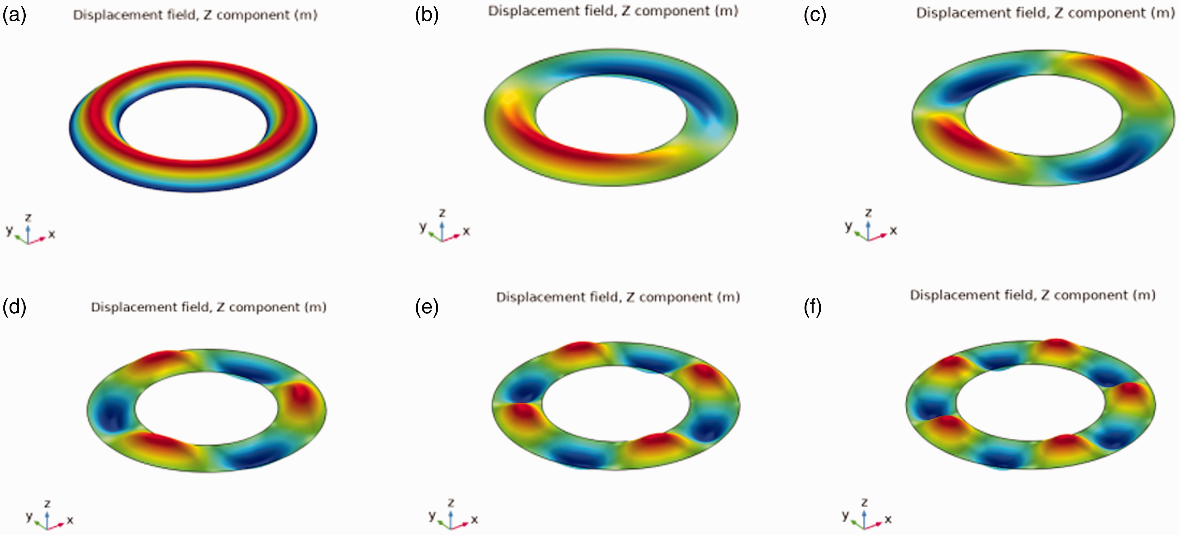
1–6 modes of oil film. (a) The 1 order. (b) The 2 order. (c) The 3 order. (d) The 4 order. (e) The 5 order. (f) The 6 order.
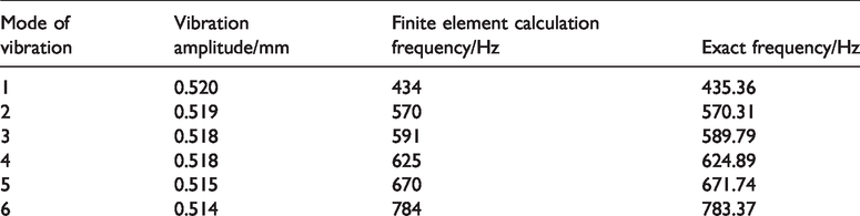
Table 1 shows the comparison between the vibration frequency and amplitude of modes 1–6. Referring to He, 24 the modal frequencies of oil film are calculated accurately and compared with those calculated by finite element method. The maximum relative error is 0.26%. At the same time, the vibration amplitude of the oil film is also shown in Table 1. With the increase of frequency, the vibration amplitude of oil film decreases. Among them, the third mode amplitude is close to the fourth mode amplitude because of the small difference between the two vibration frequencies.
Comparison of vibration frequency and amplitude of modes 1–6.
Whirl of oil film
The oil whirl of spherical bearing is easier to appear than that of traditional bearing. Rotor slippage will cause bearing wear and spalling. 18 Therefore, when the stator and rotor are in relative motion, it is very important to avoid the wear caused by slip, which will lead to the vibration of spherical bearing. When the inner ring rotor rotates along the outer ring stator, the contact force of the rotor corresponds to the normal component of gravity load. When the tangential component of the rotor gravity load is equal to the friction force, the rotor will slip. Moreover, the spherical bearing cannot only bear radial load, but also axial load. So it is more likely to slip.
When the simulation model is established, the stator spherical shell of outer ring is fixed. The boundary condition is set to full constraint. The structure of spherical bearing is rotationally symmetric. In order to reduce the calculation memory and analyze the streamline of oil film eddy more intuitively, 1/4 cross section is selected as the calculation object. However, the angular velocity of the rotor is not zero, that is to say, the model contains the velocity components in three directions.
When the rotation angle of the rotor is
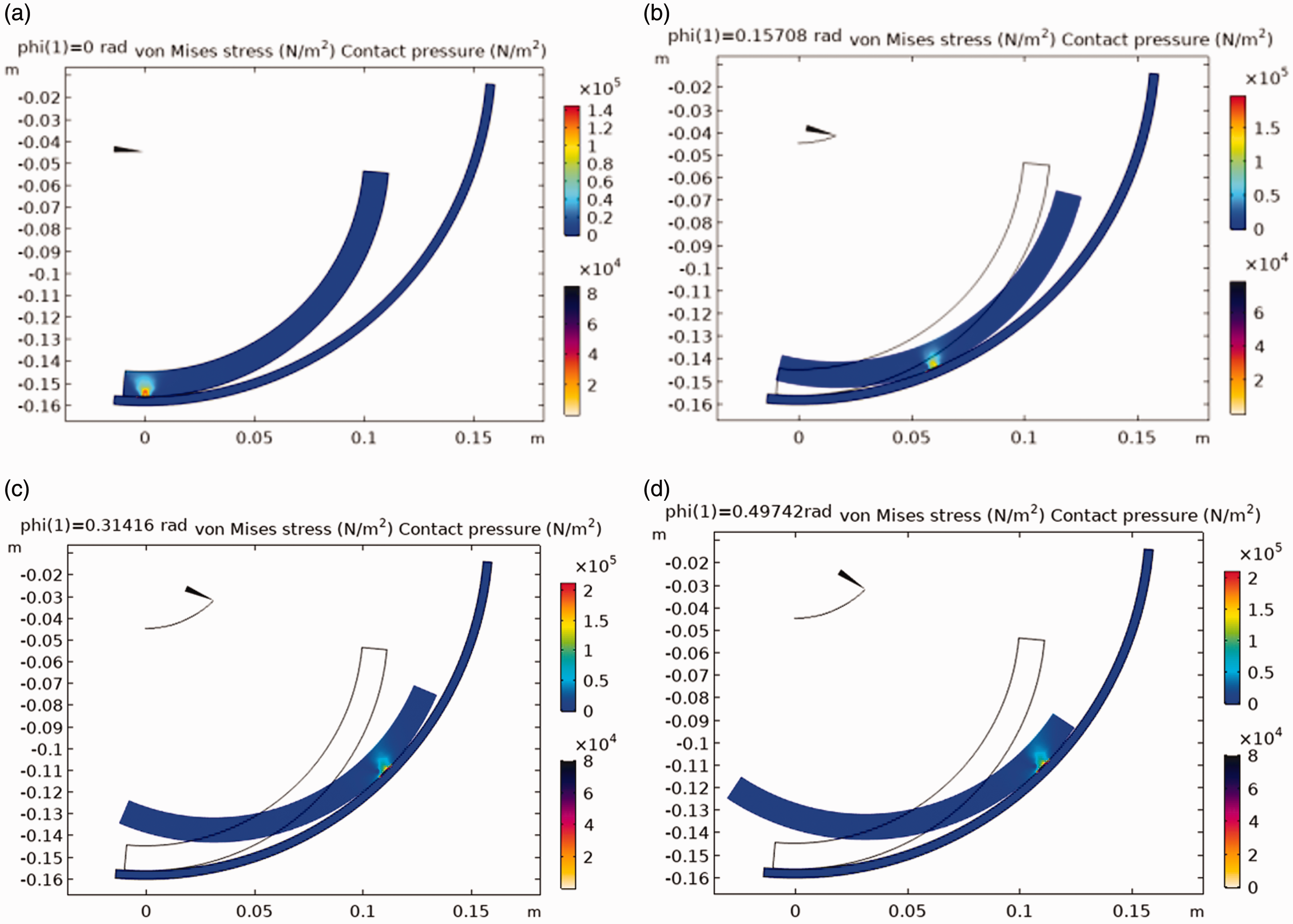
Friction stress analysis of rotor. (a) When the rotor rotation angle is 0 rad. (b) When the rotor rotation angle is 0.15708 rad. (c) When the rotor rotation angle is 0.31416 rad. (d) When the rotor rotation angle is 0.49742 rad.
The rotor rotates in the lubricating fluid, and the fluid is driven by the rotor to form a fluid wedge. At this time, the bearing capacity of the oil film is equal to the load. Therefore, the oil film stiffness determines the deflection angle of the rotor to some extent. If the rotor is set with different radial load or axial load, the suspended rotor loses balance. Return to equilibrium by changing the film pressure. However, when the balance of rotor suspension is broken again, it will cause oil whirl.
When the rotor works around the center line, the rotor axis line does not coincide with the bearing center line. This phenomenon is called oil whirl.24,25 This movement is produced by the joint action of oil film force and radial electromagnetic force on the rotor. Therefore, the whirl speed 
In this case, the Reynolds equation under the condition of oil film whirl is expressed by equation (17)

The whirl of the oil film is produced by the oil film force, which is reflected in the fact that the axis line of the rotor does not coincide with the axis line of the bearing when the rotor rotates. Therefore, the vibration frequency will also change with the oil film force. The stable operation of the rotor in the spherical bearing is realized by the balance of oil film pressure and bearing capacity. When the rotor is affected by the harmonic disturbance of electromagnetic force, the oil film pressure and bearing capacity are not equal. They can be decomposed into radial and tangential components. Among them, the tangential component is perpendicular to the displacement direction, which makes the axis rotate around the original balance point and causes the whirl of the rotor.
The dynamic oil film force can be calculated by dividing the oil film pressure along the sphere area to obtain equation (18)

Through the finite element calculation, the oil whirl cross section is obtained, as shown in Figure 10. According to the streamline distribution, the oil film speed increases with the increase of rotating speed. When the speed reaches the critical value, the oil film whirls. The force direction of stator and rotor is no longer balanced. It is reflected in the fluctuation of rotor motion track. Such nonlinear vibration eventually leads to the instability of spherical bearing system.
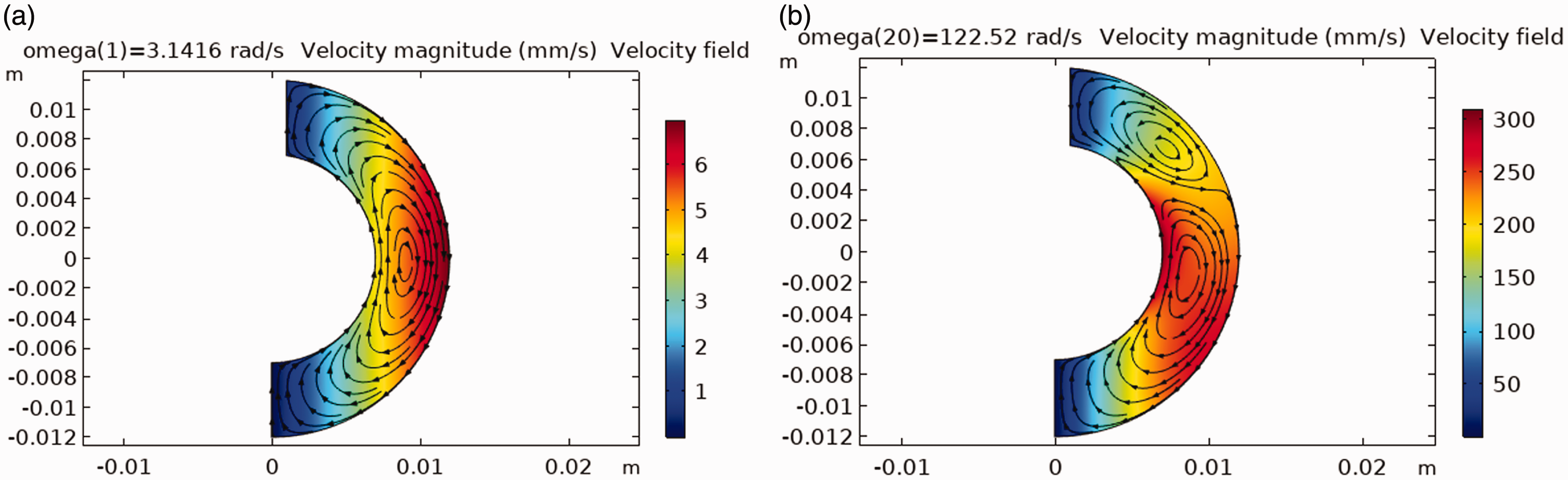
Flow line of oil film whirling section. (a) No whirling of oil film. (b) The oil film begins to whirl.
Figure 11 shows how the vibration frequency of the 1–6 modals of the oil film changes with the rotation speed. Because the rotor and stator of the spherical bearing are spherical structures, the vibration frequency of the first-order mode and the second-order mode is relatively close. Figure 12 shows the Campbell diagram of oil film whirling. The pink solid line represents the change trend of speed and frequency when the rotor speed and oil film speed are equal. The black dotted line indicates that the speed and the frequency of the oil film increase when the positive advance occurs. The blue dotted line indicates that when the oil film reverses precession, the vibration frequency decreases and then the amplitude increases with the increase of rotating speed.
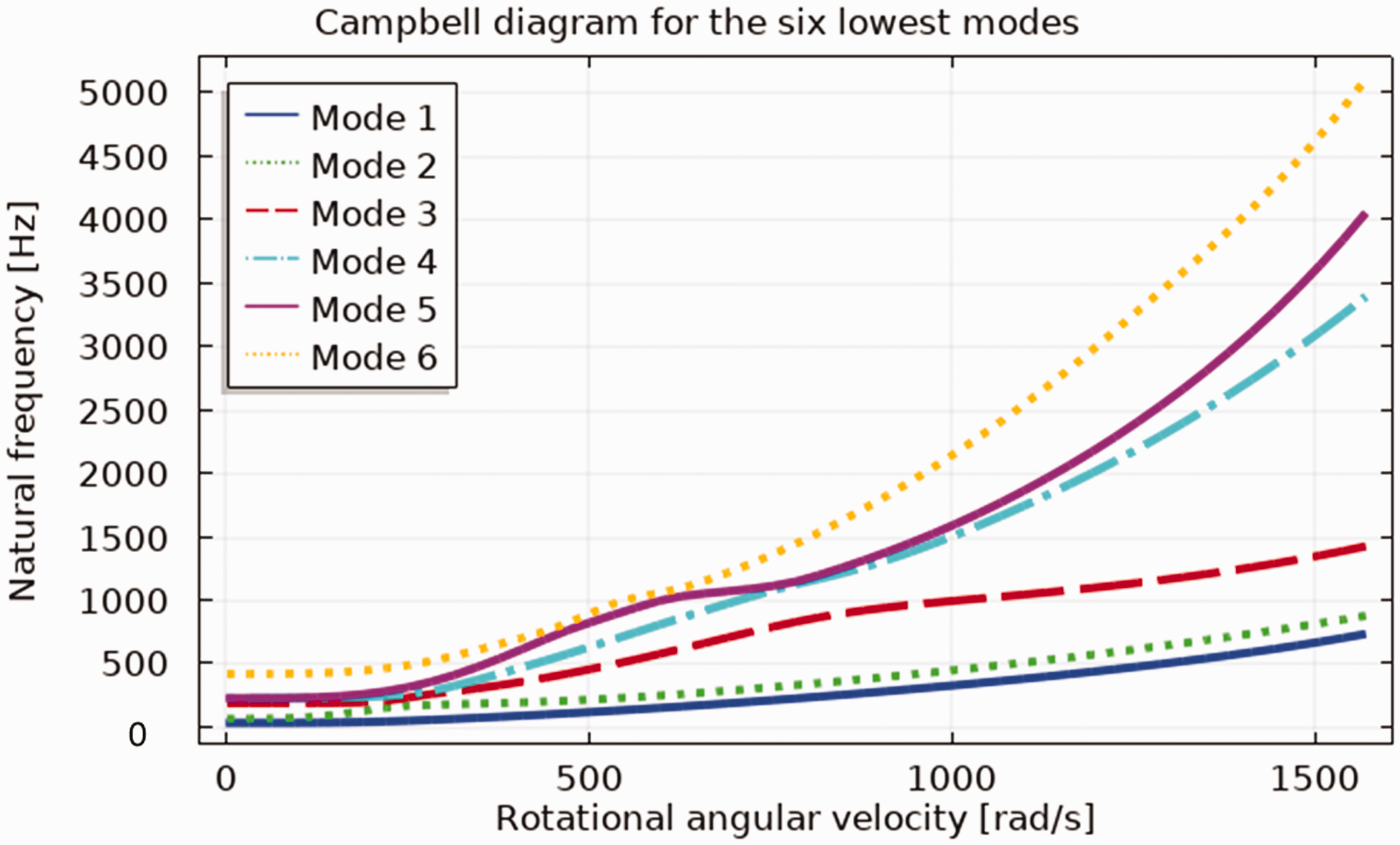
Relationship between vibration frequency and rotating speed.
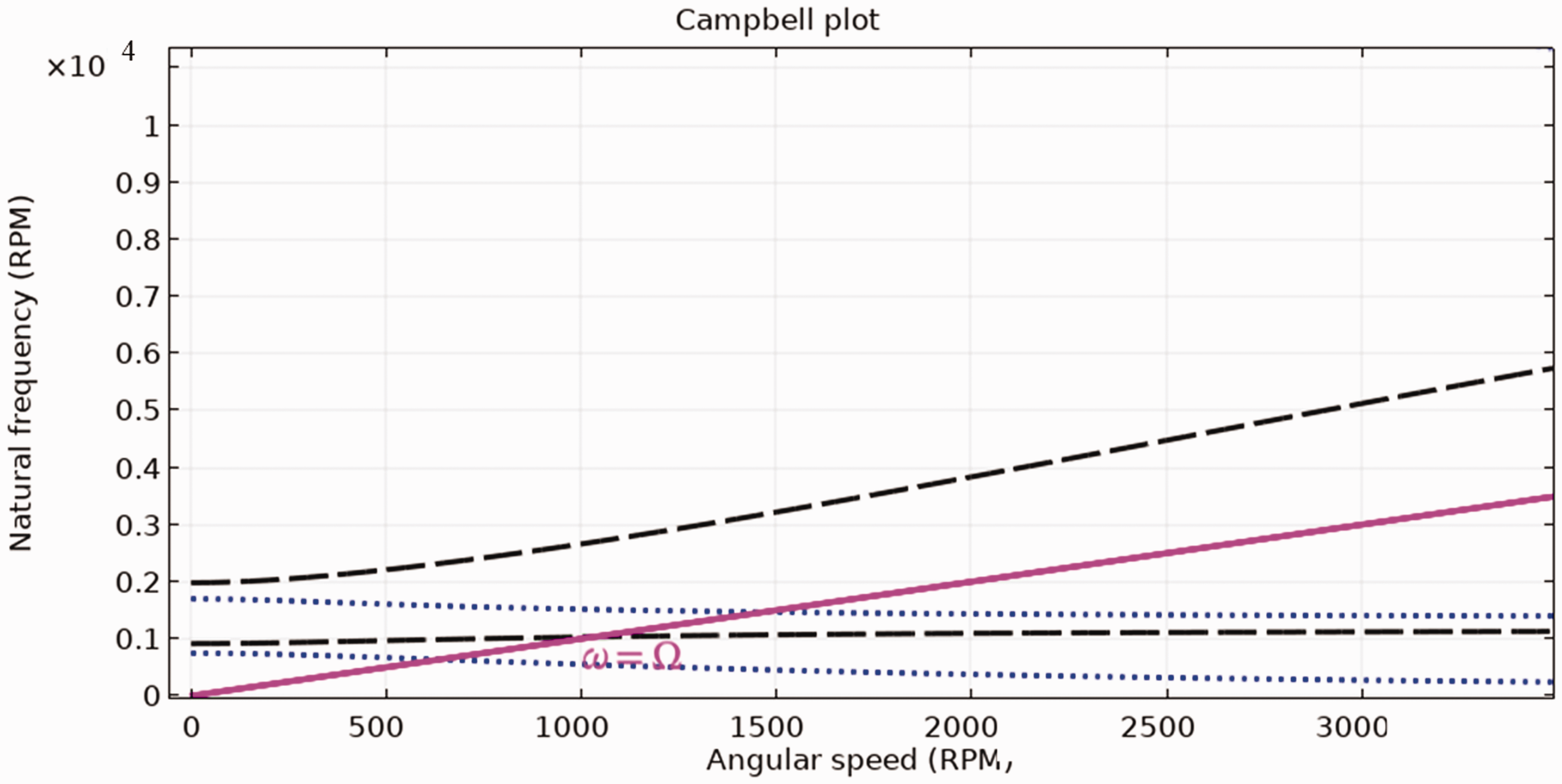
Campbell diagram of oil whirl.
Experimental analysis
In order to investigate the vibration characteristics26,27 of spherical bearings, a test platform was set up as shown in Figure 13. The testing device mainly includes rotary viscometer, vibration tester, data acquisition device, lubricant, etc. The rotor spherical shell was installed in the stator spherical shell. The shaft of the rotational viscometer was connected with the rotor ball shell. The spherical bearing was sealed with sealing ring to avoid the outflow of lubricating oil, so as to meet the sealing requirements of the football face bearing. The inner rotor was set to different speeds by a viscometer to ensure a stable average speed. The outer surface of the stator shell is provided with an oil inlet hole, and the lubricating oil entered the clearance between the stator and the rotor ball shell, so that the bearing clearance was filled with lubricating oil.
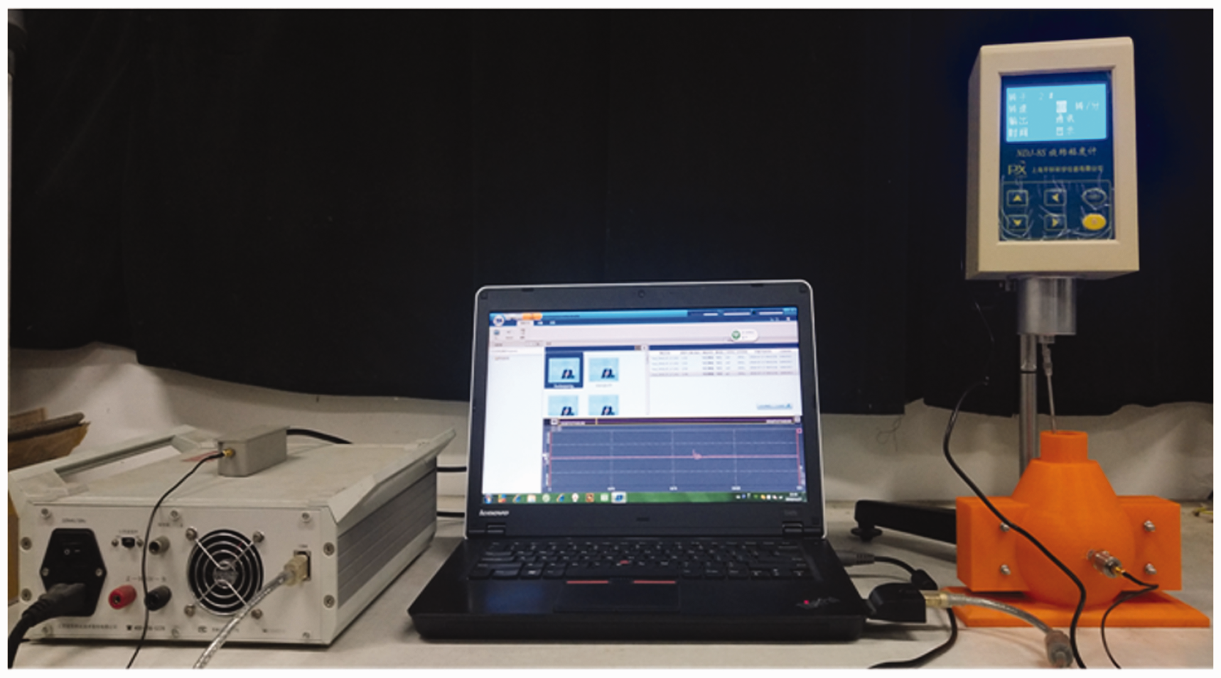
Experimental platform.
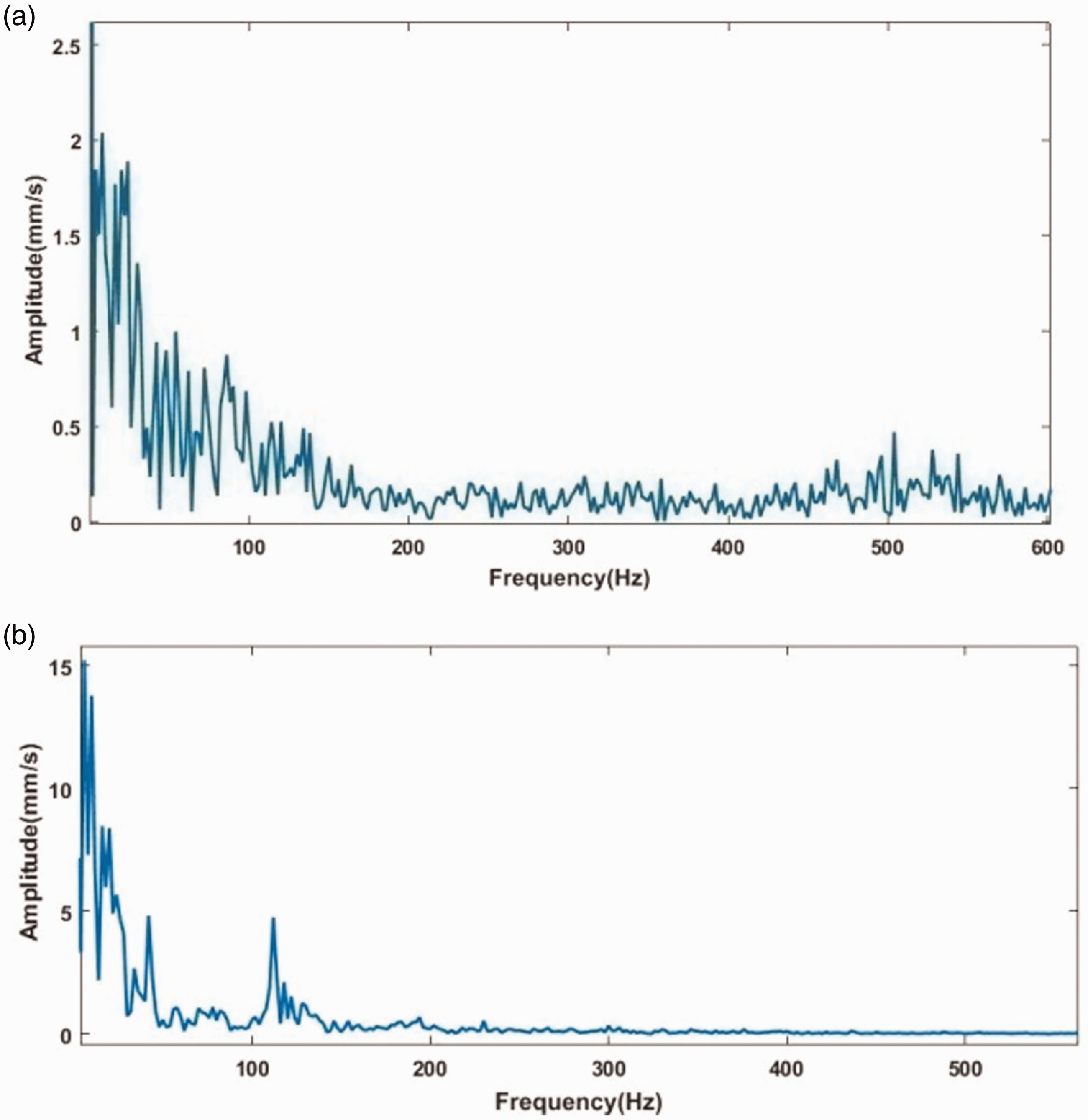
The vibration sensor probe measured the equatorial oil film vibration spectrum of spherical bearing according to the oil inlet test data, as shown in Figure 14. Among them, Figure 14(a) shows the variation of vibration amplitude with time when the spherical bearing works normally. Figure 14(b) shows the vibration amplitude changes with time when the oil film whirls. The classical modal decomposition of the measured signal data is carried out. And, the correlation coefficient of the original signal is calculated. Then, the signal with the largest correlation coefficient is selected and transformed by Hilbert transform. Finally, the relationship between vibration amplitude and vibration frequency is shown in Figure 15. It is found that the vibration amplitude of the main signals which affect the vibration of the spherical bearing is much larger than that of the normal operation when the oil film whirls. Moreover, the difference between the peak value and the average value is very large. In other words, when the oil film whirls, dry friction occured between the rotor and the stator.
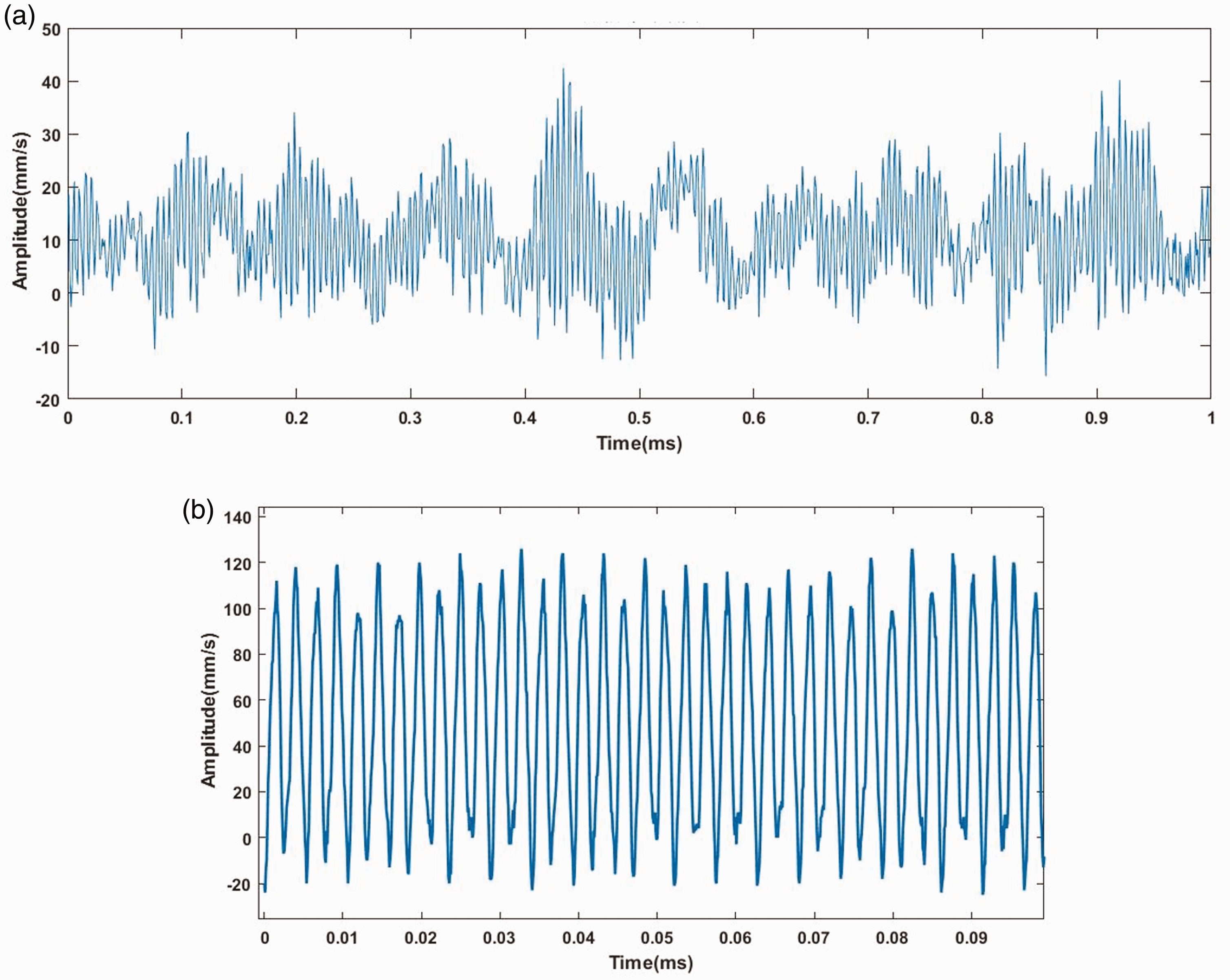
Frequency spectrum of bearing operation. (a) Normal work. (b) Oil whirling.
Empirical mode decomposition diagram. (a) Mode decomposition in normal operation. (b) Mode decomposition of oil whirl.
Discussion and conclusion
Based on the fluid structure coupling theory and vibration analysis principle, the main reasons of spherical bearing vibration are analyzed from the following aspects.
The harmonic of the radial electromagnetic force is the main cause of electromagnetic vibration of three degrees of freedom motor. The spatial distribution of the radial electromagnetic force of the 3-DOF motor is analyzed and calculated by using the analytical method. Fourier decomposition is carried out along the space angle to obtain the harmonic distribution of each order. It can be seen from Figure 4 that at the extreme value corresponding to the original signal, the order with the largest fluctuation amplitude has a greater impact on the vibration of the motor. It is found that the second harmonic has the greatest impact on the vibration of the motor. Secondly, based on the theory of fluid structure coupling, the exact solution is obtained by the principle of check. The oil film pressure distribution and oil film thickness distribution are compared when the rotor wall surface is smooth and rough. In Figure 6, excessive roughness of the rotor surface can cause the bearing oil film to break. In addition, it will lead to uneven distribution of oil film thickness and reduce the service life of bearings. In addition, the mode of oil film is analyzed by finite element method. From the data in Table 1, it is found that the vibration frequency of the oil film is inversely proportional to the amplitude. The process of rotor sliding and the force on the rotor are analyzed. At the same time, the oil film model, eddy streamline diagram, positive and negative eddy analysis of oil film are simulated. In the process of rotor sliding, the stress of rotor is larger than that of stator, that is to say, the surface of rotor is more easily worn. Finally, the effectiveness of the spherical support structure is verified by building an experimental platform. At the same time, the vibration amplitude and oil whirl of the spherical bearing were measured. In addition, the experimental data are decomposed into modes. By comparing the relationship between vibration amplitude and vibration frequency, it is found that oil whirl causes negative vibration growth of spherical bearing, which leads to dry friction between rotor and stator.
In a word, this paper analyzed and calculated the cause of the vibration of the motor. The fourth-order harmonic of radial electromagnetic force, the roughness of rotor surface, the slip and oil whirl in the process of rotor rotation and other factors cannot be ignored. And the experimental analysis is carried out, which provides a good theoretical basis for the practical application and further optimization design of spherical bearing.
Footnotes
Declaration of conflicting interests
The author(s) declared no potential conflicts of interest with respect to the research, authorship, and/or publication of this article.
Funding
The author(s) disclosed receipt of the following financial support for the research, authorship, and/or publication of this article: This research was funded by the National Natural Science Foundation of China, grant No. 51577048, 51877070, 51637001, the Natural Science Foundation of Hebei Province of China, grant No. E2018208155, the Talent Engineering Training Support Project of Hebei Province, grant No. A201905008, the National Engineering Laboratory of Energy-saving Motor & Control Technique, Anhui University, grant No. KFKT201901, Hebei Province Higher Education Science and Technology Research Key Project, grant No. ZD2018228.