
Abstract
It is seen that blisk will be in a nodal diameter vibration state under the engine order excitation, which can be simulated by traveling wave excitation. The nodal diameters rotate on the blisk and it is necessary to identify the specific form of the nodal diameter vibration. Here, based on the determination of nodal diameter vibration parameters, a novel identification method of the nodal diameter vibration was proposed through the experimental test. Specifically, a traveling wave excitation system was built using the LabVIEW control software and noncontact magnetic exciters. Based on the description of resonant state of blisk, the identification principle formulas of the nodal diameter vibration were derived and the identification procedure was given. Taking uncoated and coated blisks as the research objects, the identification method was demonstrated. The identification results showed that the shape, direction, speed, and period of nodal diameter vibration were successfully obtained by the proposed method. In addition, it was found that coatings have a damping effect on blisk. Because of the coating introduction, the blisk vibration response was reduced, the rotation speed of nodal diameter was slowed down, and the rotation period of nodal diameter was increased.
Introduction
Blisk is a new structure of modern aero engine. Compared to the traditional structure, blisk can improve the aero engine performance, simplify the rotor structure, and increase the aero engine reliability. In real operating conditions, blisk is usually subjected to engine order excitation as the blades rotate through the stationary disturbance in the turbine engine flow field, where the excitation order is the number of stationary equally spaced disturbance. 1 In addition, the engine order excitation is a function of the amount of aerodynamic airflow disturbance applied to the rotor. 2
In the development process of blisk, it is necessary to obtain the vibration characteristics under the engine order excitation. Much of the theoretical work about vibration characteristics have been done. For example, Duan et al. 3 created a high-fidelity finite element (FE) model of bladed disk and analyzed the forced response under the higher engine order excitation. Bladh et al. 4 studied Craig–Bampton (C–B) method of CMS for mistuned blisk and considered engine order excitation as the external excitation force vector. Zhou et al. 5 performed forced response prediction for the last stage blade of steam turbine under low engine order excitation by computational fluid dynamics and finite element analysis. He 6 proposed a method, which can calculate the frequency of a nonlinear conservative oscillator accurately based on the cubic-quintic Duffing equation. The mathematical methods can be applied to solve vibration characteristics of structure or simulate the engine order excitation theoretical of the above research. However, in the above researches, no relevant experiments were found.
In addition, the blisk belongs to a kind of fluid structure and so its vibration problem can be effectively studied by the coupled variational theory, which is established by the semi-inverse method. Therefore, the relevant analysis and calculation methods can be used as references for vibration analysis of blisks. For example, He and Sun 7 proposed an effective method, which can establish the variational formulation for the thin film equation and fill the vacancy in this research field. He 8 presented a generalized variational principle of two-dimensional (2D) unsteady compressible flow for the airfoil based on governing equations, boundary conditions, and the semi-inverse method. Liu 9 proposed a general form of variational principles for 3D unsteady transonic potential flow aimed at providing a general theoretical basis for the finite element analysis or the other variational approaches. According to the Liu’s ideas, He 10 obtained a few new variational principles for the 3D unsteady flow, which can avoid the Lagrange crisis.
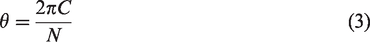
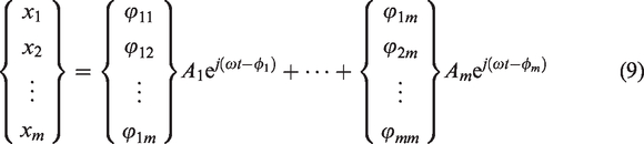
It is important to accurately describe the vibration characteristics of blisk in laboratory environment. Because of the expensive and complicated experiment devices of rotating blisk, many researchers simulated the engine order excitation with point loads by applying the excitation to the blades of stationary blisk.11–13 The key idea of these research works is that engine order excitation can be simulated by applying the same amplitude and frequency sinusoidal excitation to each blade but the excitation signals between adjacent blades are shifted in phase, which can be expressed as


Based on the above idea, many researchers have developed a variety of traveling wave excitation system of blisk. Jones and Cross 1 designed a traveling wave excitation system for stationary blisk to explain the forced response localization and amplification, which can test different blisks with varying sizes using either acoustic or magnetic excitation. Garafolo and Sawyer 14 modified the LabVIEW controller of the above system to allow for multiple mode excitation of blisk. Holland et al. 15 proposed an integrated testing and calibration procedure to identify the mistuning and simulate traveling wave excitation for blisk. Gibert et al. 16 described an experimental setup to measure the dynamic response of blisk under traveling wave excitation and the excitation force was provided by piezoelectric actuators and phase-shifting circuit. The methods mentioned in the above studies can achieve the simulation of traveling wave excitation basically. However, some systems are not robust enough because of complex circuits or introduction of additional mass. In addition, the equipment may be complicated, which makes it difficult to perform experiments in the general laboratory.
It is well known that blisk will be in a nodal diameter vibration state under the traveling wave excitation. Generally, due to the lack of direct description for the nodal diameter vibration, scholars17–21 usually study the phenomenon of the nodal diameter vibration through natural characteristics indirectly. For example, Yao et al. 17 performed dynamic characteristics assessment and analysis for blisk through nodal diameter spectrum of modal shapes. Nyssen et al. 18 performed an experimental modal analysis for academic two-stage drum and proposed the relationship between nodal diameter and frequency. Kruse et al. 19 summarized the information about nodal diameter and nodal circle characteristics for tuned blisk by a figure of natural frequency versus the number of nodal diameter. Through the modal analysis of blisk, the relationship between the number of nodal diameter and the natural frequencies can be obtained. However, the manner that describes the phenomenon of the nodal diameter vibration by means of natural characteristics can only reflect the changes of nodal diameter number, but cannot reveal the vibration state of blisk completely. Moreover, the description of real nodal diameter vibration is less addressed numerically or experimentally in literature.
Coating is a kind of damping material to spray or paste onto the surface of structure and has been applied to increase the structure damping capacity widely. Viscoelastic coating material and hard coating material are the two most typical coating damping material. Viscoelastic coating material is the organic polymer material, which need to be attached to the surface of structure in order to consume vibrational energy, while hard coating is prepared by metal, ceramic, or their mixtures and needs to be deposited on the surface of structure to suppress the destructive vibration. Till now, many researches have been done about coating such as the identification of mechanical parameters, 22 the evaluation of damping characteristics, 23 vibration analysis of viscoelastic damping structure, 24 etc. With regard to the coated blisk structure, Liu et al. 25 studied the dynamic characteristics of coated blisk with synchronized switch damping. Xu et al. 26 proposed a novel mistuning identification method of coated blisk based on CMM. At present, to understand the damping mechanism of blisk coating, it is necessary to perform the nodal diameter vibration test or analysis for coated blisk.
In this paper, a traveling wave excitation system was established and a novel identification method of the nodal diameter vibration for blisk was presented. This study is organized as follows. In the following section, the phenomenon of the nodal diameter vibration was described briefly and parameters are determined to describe the nodal diameter vibration. Next, a traveling wave excitation system is developed for the purpose of simulating engine order excitation. Detailed descriptions of the overall design scheme, hardware system, and software system are given. Subsequently, the identification principle of the nodal diameter vibration is described and the relevant test process of the nodal diameter vibration is presented. Further, a case study is carried out to verify the effect of the traveling wave excitation system and identification method. The characteristic variation of the nodal diameter vibration between uncoated blisk and coated blisk are compared and discussed. The conclusions are listed in the last section.
Description of the nodal diameter vibration of blisk
Here, a finite element model (FEM) developed by ANSYS was created for an academic blisk to describe the characteristics of the nodal diameter vibration and shown in Figure 1. The FEM was completely generated by the 3D solid element SOLID45 in ANSYS, which included 22,800 nodes and 10,560 elements.
The FEM of the academic blisk.
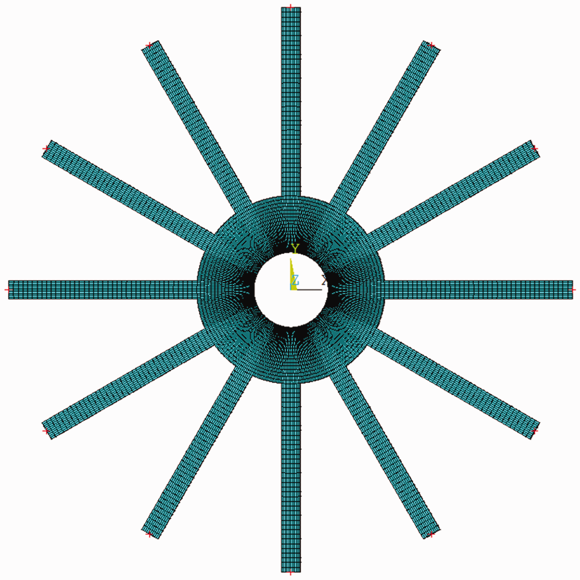
Modal analysis was performed to obtain modal shapes and the corresponding natural frequencies in the first bending modal family of the academic blisk. Three modal shapes of blisk are shown in Figure 2. It can be seen that nodal diameters exist clearly in these mode shapes. Because of the cyclic symmetry of tuned blisk, the nodal diameters will rotate and appear anywhere in the real operation condition. Intuitively, the nodal diameters rotate around the axis of blisk at a specific speed, which cause the amplitude of each blade to change between maximum and minimum values. At any time, the displacements of blade corresponding to the nodal diameter are the smallest. This phenomenon can be called as the nodal diameter vibration. The above description was entirely based on the modal analysis results using analytical model rather than the test results. This paper will describe the above-mentioned nodal diameter vibration specifically through the experiment test.
The modal shapes of blisk: (a) 0th nodal diameter; (b) 1st nodal diameter; (c) 3rd nodal diameter.
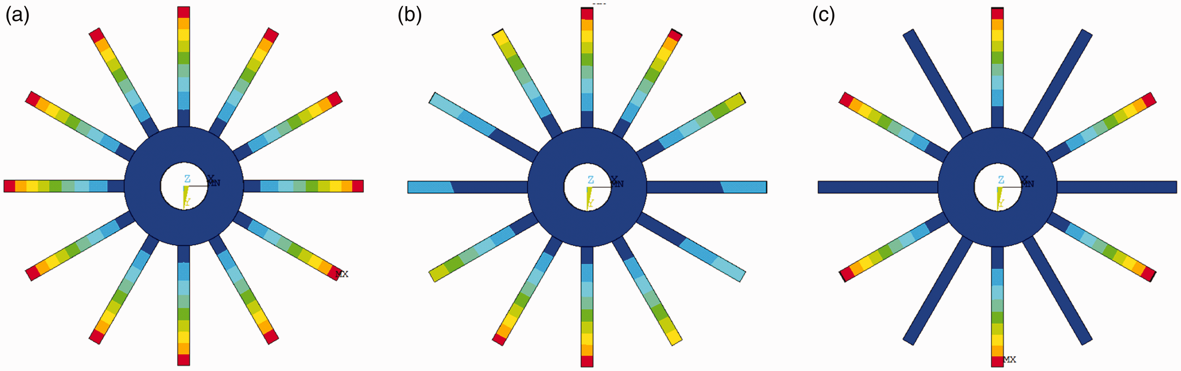
As shown in Figure 3, in order to describe the nodal diameter vibration in detail, three parameters were determined. They are the nodal diameter motion direction D, the nodal diameter motion speed
Three parameters of the nodal diameter vibration.
Setting up of traveling wave excitation system
Scheme design
The functional requirements of traveling wave excitation system need to be determined firstly. According to the principle of traveling wave excitation and the geometric features of blisk, the following capabilities must be available in the traveling wave excitation system:
(a) The capability of multipoint excitation
Due to the special structure of blisk, the system must provide independent excitation source for each blade to achieve multipoint excitation function.
(b) The capability of high-precision excitation
In order to avoid the effects of additional mass and stiffness caused by traditional exciters, a noncontact excitation manner is required to improve the accuracy of excitation.
(c) The capability of high-precision test
The sensors and data acquisition analyzer in the system need to have high acquisition accuracy to meet the requirement of capturing high-fidelity signals.
Considering the above functional requirements, the final design scheme of the traveling wave excitation testing system was determined and shown in Figure 4. The excitation part consists of signal generator, analog output module, power amplifier, noncontact magnetic exciter, etc. The hammer is used for the auxiliary test and the special fixture is designed to hold the blisk and magnetic exciters. The devices of data acquisition part include accelerometers or laser vibrometers, data acquisition analyzer, and computer for instrument controlling.
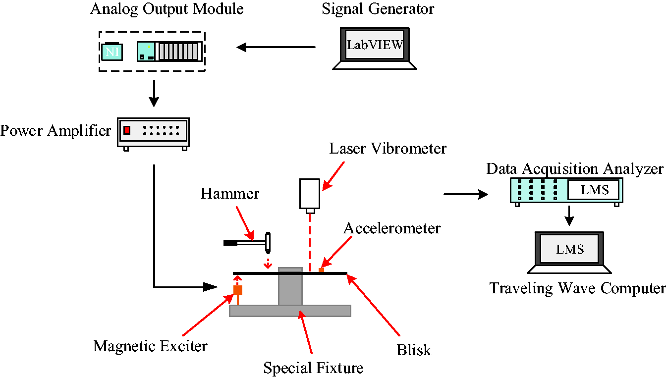
The schematic diagram of the traveling wave excitation testing system.
Hardware system
According to the design scheme of the traveling wave excitation testing system, the relevant hardware were chosen or designed and described as follows.
The signal generator was developed by LabVIEW, which controlled the parameters of the traveling wave excitation signal. Here, the NI-9263 and NI compact DAQ-9189 analog output modules were selected to complete the digital-to-analog conversion of signals generated by signal generator. In order to meet the requirement for noncontact excitation, the YE15401 magnetic exciters were equipped, which were driven by YE5876 power amplifier.
The special fixture was designed based on the structural feature of blisk and the positions of magnetic exciters. The magnetic exciters on the fixture can not only be moved radially to meet the need for multipoint excitation, but also can be moved vertically to change the distance between exciters and blisk. The quality of fixture was so heavy that it can play a good role in fixing and supporting.
LMS SCADAS Mobile Front-End data acquisition analyzer with high conversion accuracy and sampling frequency can be used to obtained high-fidelity signals. The B&K 4517 lightweight piezoelectric accelerometers were selected to pick the acceleration response signals of blisk. The PCB 086C01 modal tuned ICP impact hammer can be used to test the amplitude and frequency of structure generated by pulse excitation.
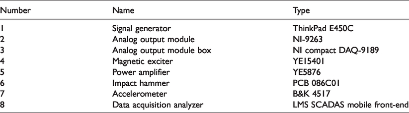
The hardware system is shown in Figure 5. The names and corresponding types of device in the system are listed in Table 1.
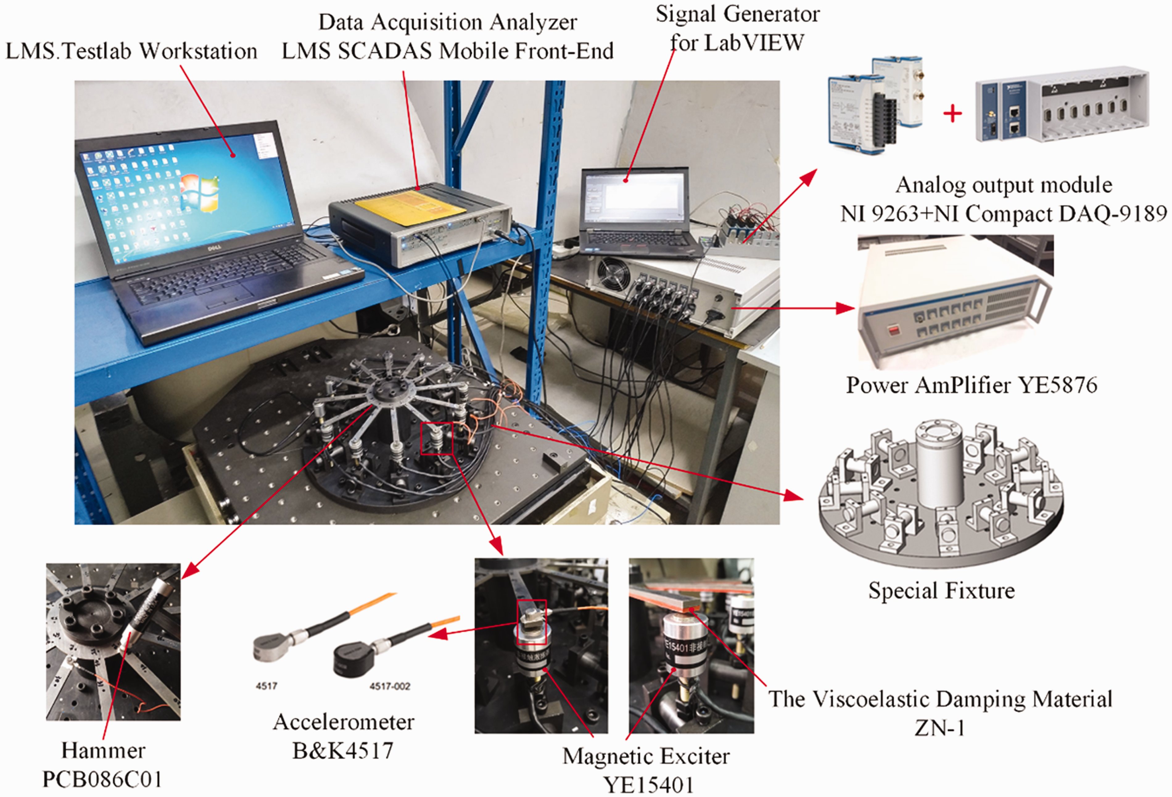
The hardware system.
The names and corresponding types of device.
Software system design
In order to support the hardware operation and meet the requirement of traveling wave excitation, it is necessary to develop the corresponding controlling software system. The signal generator need to provide not only the multichannel sinusoidal excitation signal whose parameters are adjustable independently, but also fix or sweep frequency excitation signals. Summarizing the description of the above functions, the logic structure diagram of the software system is shown in Figure 6.
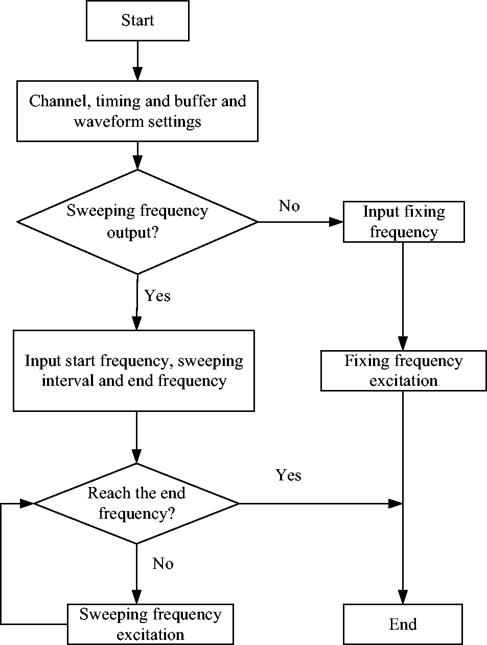
The logic structure diagram of the software system.
LabVIEW programming based on virtual instruments (VIs) mainly includes three parts: front panel design, block diagram design, and program debugging operation. Compared with the physical instruments, the LabVIEW front panel is equivalent to the instrument panel, which consists of input components and display components. The LabVIEW block diagram is equivalent to functional components in the instrument box, which is the actual executable code written in the graphical programming language.
Here, the front panel of the signal generator is shown in Figure 7. The design concept of the front panel mainly include channel setting, timing and buffer setting, waveform setting, and output waveform display. Channel setting is used to select the physical channels and set the output voltage range of the physical channel. The timing and buffer setting is responsible for selecting the sampling clock and setting the sampling frequency of the output signal. The waveform setting is used to set the parameters of the output signal such as amplitude, frequency, and so on. The waveform of the output signal can be displayed in the waveform display area directly.
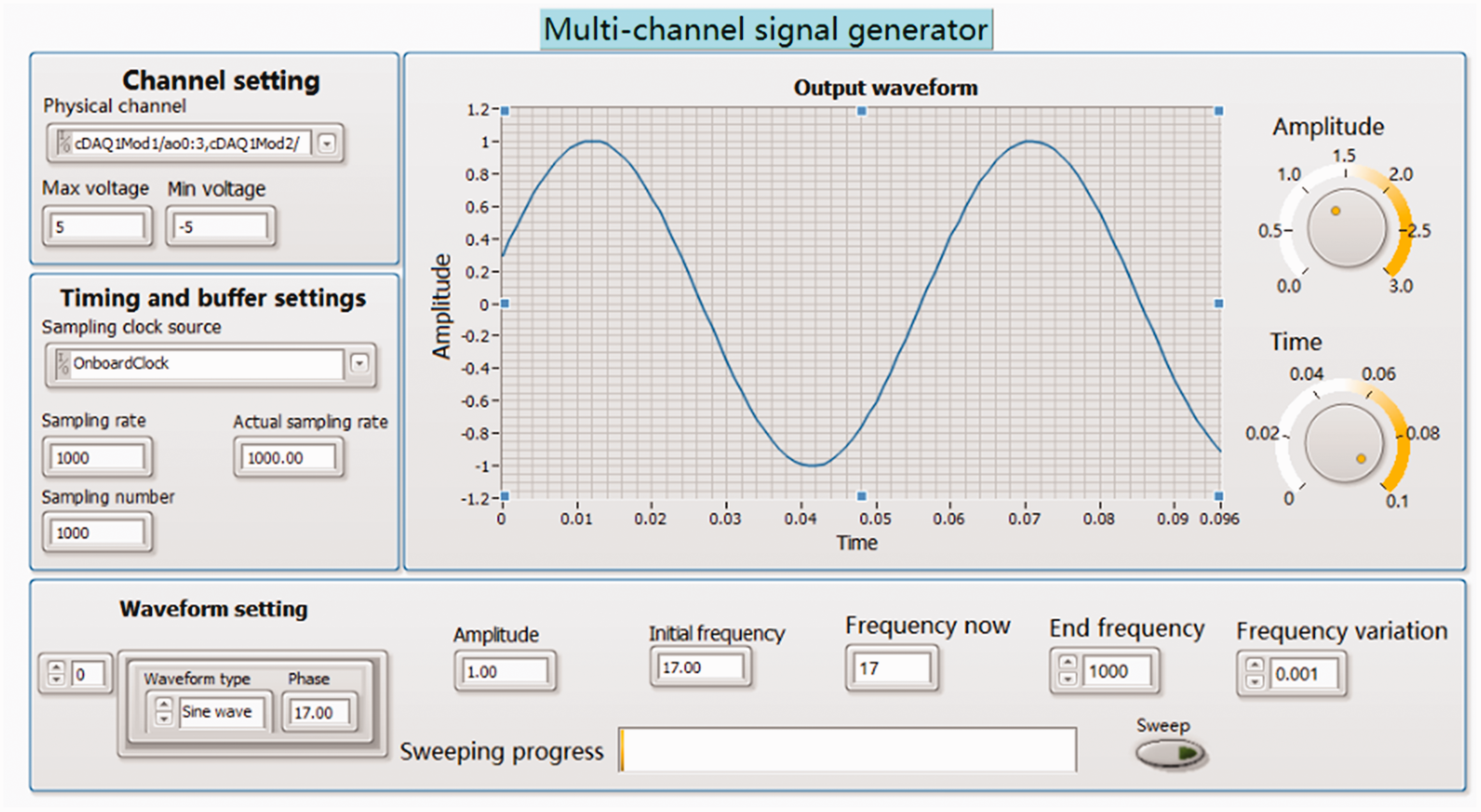
The front panel of the signal generator.
The design idea of the block diagram is described as follows. Firstly, “DAQmx create virtual channel.vi” is called to create virtual channels, which are added into the signal output task. Then, “DAQmx timeing.vi” is called to set the sample frequency of the output signal and create the required buffer area. Next, the output waveform is created in “Basic function generator.vi” and the sampling data is written into the specified virtual channel through “DAQmx writing.vi” at the same time. Finally, “DAQmx start task.vi” and “DAQmx stop task.vi” are called to start or stop the task, respectively. The VIs involved in the LabVIEW programming process are shown in Figure 8.
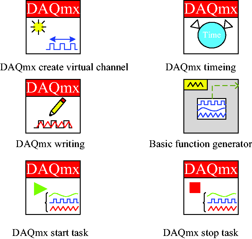
The virtual instruments involved in the programming process.
Method of the nodal diameter vibration identification
Identification principle
When the excitation frequency equals to the natural frequency, blisk will be in a stable resonant condition. The vibration response achieves the peak in the current order and the response of other modes is minimized. The nodal diameter vibration of blisk is closely related to its resonance. Therefore, the identification principle of the nodal diameter vibration for blisk can be confirmed by analyzing the resonant response of blisk.
Blisk is considered as a multi-degrees-of-freedom (DOFs) system that contains 
Assuming the applied forcing vector 
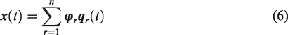

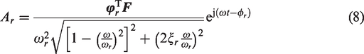
Next, combining equations (6), (7), and (8), the expression of the system vibration response can be expressed as
When the excitation frequency equals to the rth natural frequency 
Equation (9) may be rewritten as
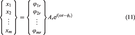
It can be approximated from equation (11) that the other mode vibration response amplitudes in the modal coordinate can be considered as 0. If resonant responses of enough measuring points are tested, the nodal diameter shape corresponding to a certain order of blisk can be obtained. Since the above excitations are of the same phase, the measuring points on blisk are under resonant condition with the same phase, that is, the points achieve the maximum or minimum amplitude simultaneously.
With reference to equation (11), if forces with the same excitation amplitude and frequency but different phases are applied to each sector of blisk, the responses of the same position on each sector of blisk can be expressed as
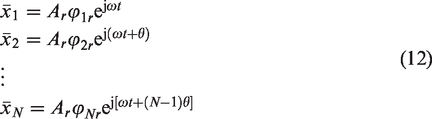
From equation (12), because of the phase differences between the exciting forces of different blade, the vibration forms of measuring points on adjacent blades are different at a certain time and then the nodal diameter phenomenon occurs. The amplitudes of measuring point change periodically with the change of time, which cause the nodal diameters to rotate at a certain speed. The relevant formula for the nodal diameter vibration speed
Identification procedure
In this section, the identification procedure of the nodal diameter vibration is described in Figure 9 and it can be divided into the following four key steps.
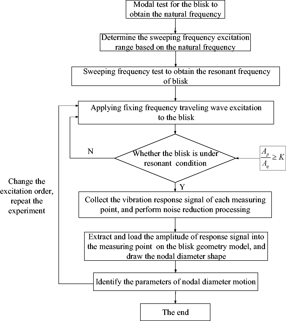
The identification procedure of the nodal diameter vibration.
Obtaining the resonant frequency of blisk
Modal test is performed with the combination of impact testing and stepped sine sweeping frequency excitation test. Firstly, the parameters of impact testing is determined based on the results of finite element analysis (FEA). Next, the natural frequencies are obtained by impact testing. Finally, taking the natural frequency as reference, stepped sine sweeping frequency excitation test is performed for the purpose of obtaining resonant frequencies of blisk.
2. Applying fixing frequency traveling wave excitation to blisk
The frequency and phase of each channel excitation signal is set up according to the resonant frequency and excitation order in signal generator. The power amplifier gain is adjusted to provide sufficient energy to drive the magnetic exciter. Then, fixing frequency excitation is applied to blisk in order to keep blisk in a stable resonant condition.
Here, a standard to determine if the structure is in a stable resonant condition is given. When structure is in the resonant status, the resonant response amplitude is much larger than that in the nonresonant status. The structure is considered to be in a resonant condition usually when the following equation is satisfied
3. Collecting the stable vibration response signal of blisk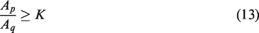
The collection of each measuring point vibration response signal is completed in sequence by using two accelerometers. An example is illustrated to explain the test process in detail. Firstly, the vibration response tests of the outermost circle measuring points of No. 1 and No. 2 blade are carried out. Then, the accelerometers are removed and attached to the outermost circle measuring points of No. 2 and No. 3 blade. After the tests of the outermost circle 12 measuring points are completed, the accelerometers are moved inward radially. The experiment is over until the tests of all the measuring points are completed. The specific procedure and geometric model are shown in Figure 10.
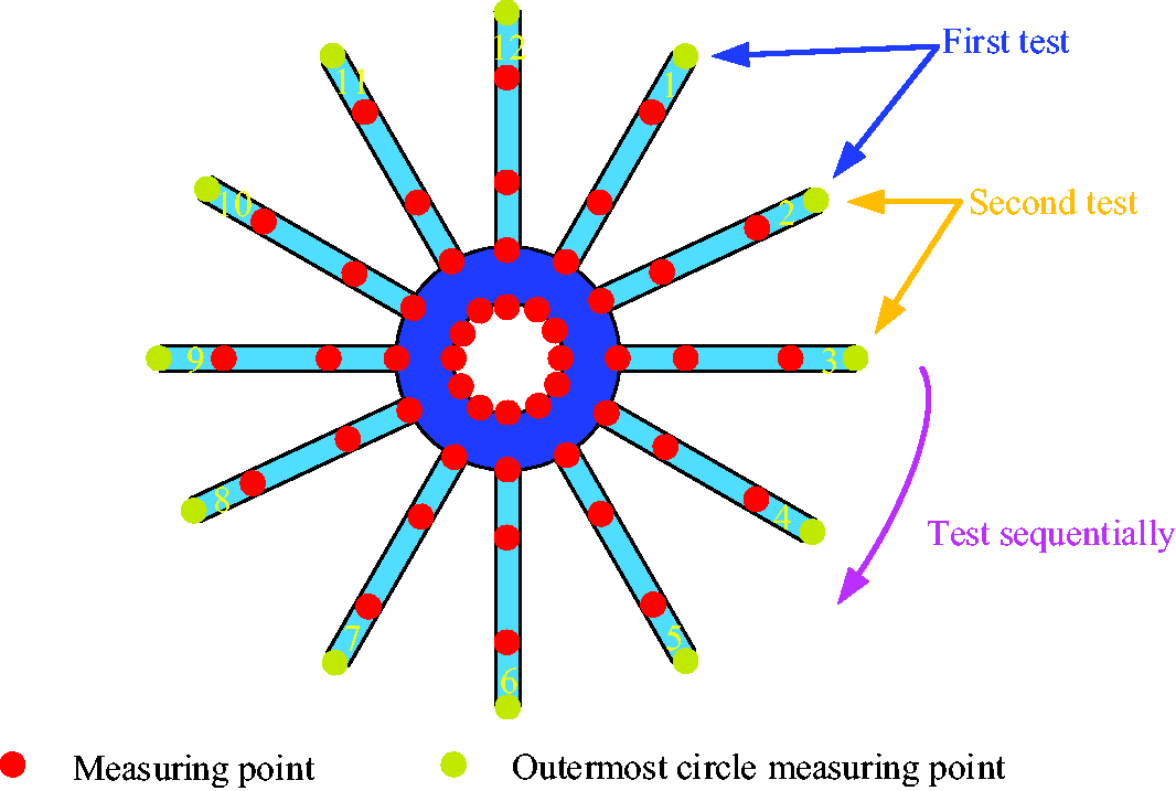
The geometric model and measuring point distribution of blisk.
After the vibration response tests, the vibration response time-domain signals were subjected to noise reduction processing in order to improve the signal quality.
4. Drawing the nodal diameter shape of blisk and identifying the nodal diameter vibration
The vibration response time-domain signals are compared and analyzed to find out the spatial position relationship of measurement points. An example is elaborated to explain the process in detail, as shown in Figure 11. First, the vibration response time-domain signals of No. 1, No. 2, and No. 3 blade are compared. When the amplitude of No. 2 measuring point is h, No. 1 measuring point has vibrated for time t. When the amplitude of No. 3 measuring point is h, No. 2 measuring point has vibrated for time t. According to this relationship, the three vibration response time-domain signals can be correlated: when the amplitude of No. 1 measuring point is 0, the amplitude of No. 2 measuring point is h and the amplitude of No. 3 measuring point is H. Then, the amplitudes of measuring points can be considered as the spatial position of measuring points. According to this relationship, the amplitudes of measurement points are loaded into the geometric model in Figure 10 to complete the drawing of nodal diameter shape.
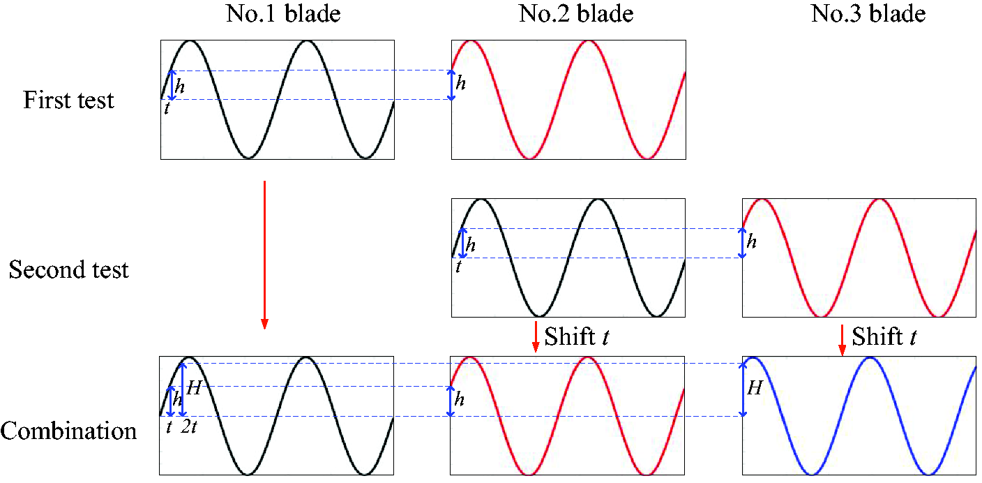
The correlation process of the time-domain signal.
The parameters of the nodal diameter vibration can be identified according to the nodal diameter shapes and vibration response time-domain signals. The amplitudes at different moments of the outermost circle measuring points of blisk can be expressed as a harmonic form, as shown in Figure 12. The identification process of nodal diameter vibration parameters is as follows. First, the direction D of the nodal diameter vibration can be known according to the serial number change order of blade with 0 amplitude. Second, the nodal diameter transformation period T and the nodal diameter vibration speed 
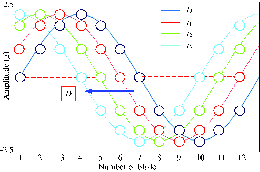
The harmonic form of amplitude of each measuring point at different times.
Until now, all the parameter identification the of nodal diameter vibration have been completed.
Case study
In this section, an academic blisk is chosen to verify the validity of the traveling wave excitation system and the proposed method. The experimental structures are shown in Figure 13. The material parameters and geometric parameters of the experimental structure are listed respectively in Tables 2 and 3.
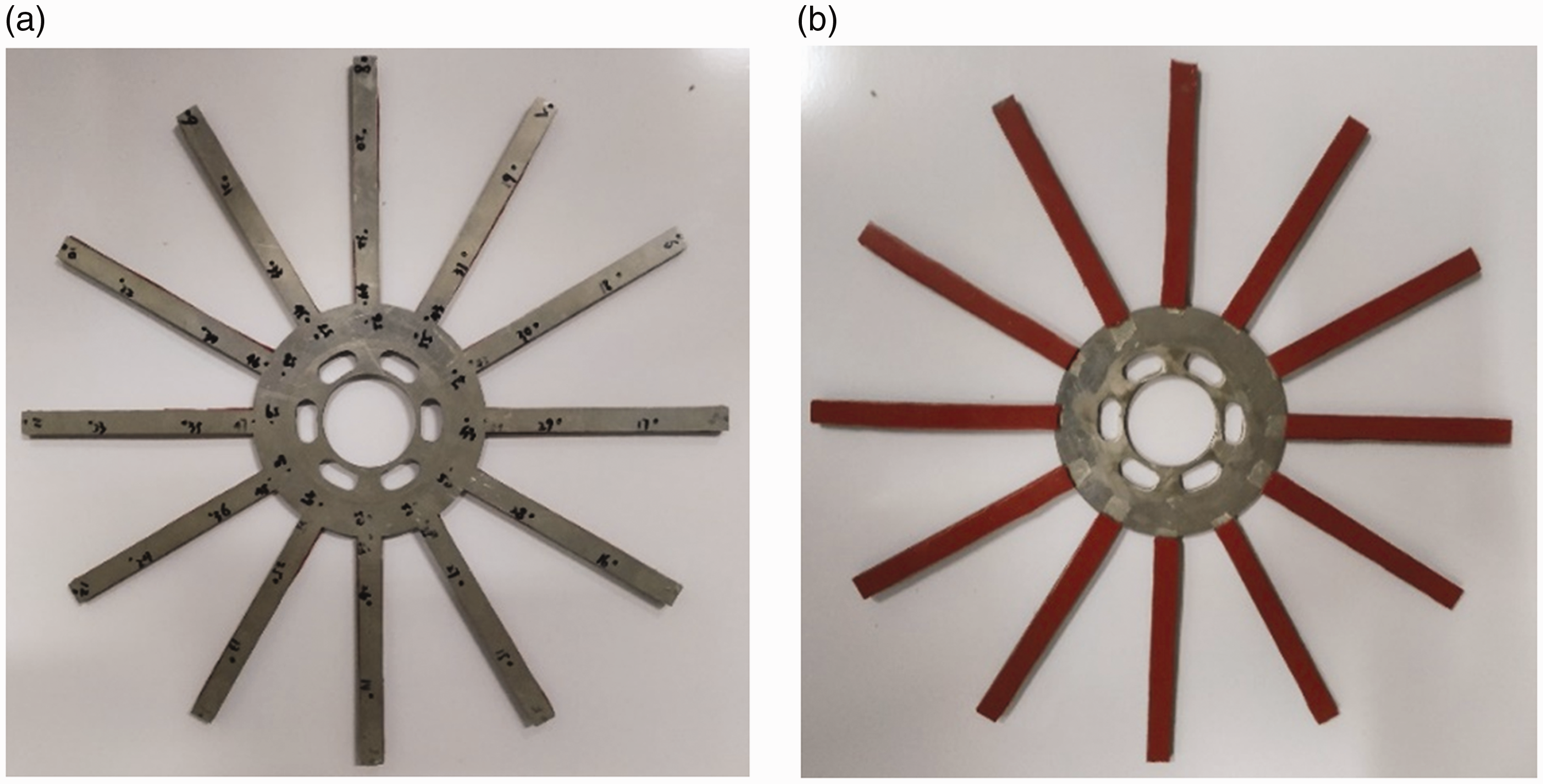
(a) Uncoated and (b) coated blisks.
The geometric parameters of blisk (mm).

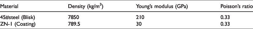
The material parameters of blisk.
Resonance frequency test
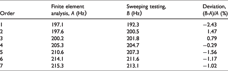
The first step is to determine natural frequencies by the impact test, which will be considered as the reference of determination of the stepped sine sweeping frequency excitation range. The settings of impact testing parameter in data acquisition analyzer are based on the results of FEA, where bandwidth, frequency resolution, and sampling frequency are set as 0–1280 Hz, 0.15625 Hz, and 2560 Hz, respectively. Frequency response function and coherence curve obtained by impact testing are shown in Figure 14. Next, the stepped sine sweeping frequency excitation is performed by magnetic exciters, where sweeping intervals are determined by natural frequencies. The resonance frequency and response can be obtained directly from the results of data acquisition and analysis software. For example, when the excitation frequency is 192.3 Hz, the vibration response waterfall figure is shown in Figure 15. The vibration response amplitude corresponding to each excitation frequency is extracted to form the “frequency–response” curve, as shown in Figure 16. All of the resonance frequencies obtained by test are listed in Table 4.
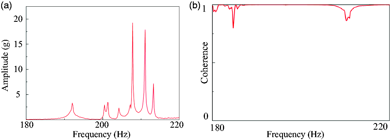
The FRF and coherence curve obtained by impact testing: (a) the FRF of blisk; (b) the coherence between two impacts.
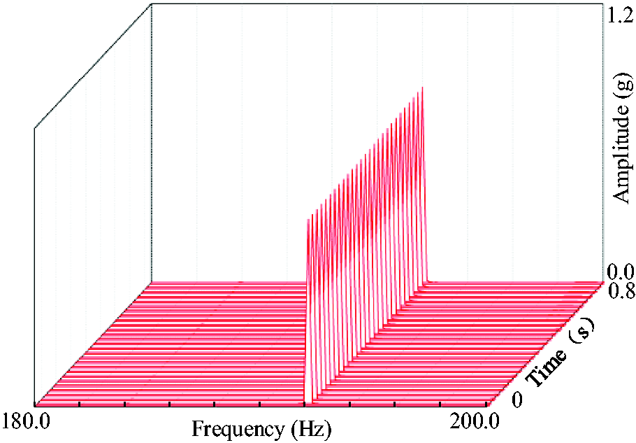
The vibration response waterfall at 192.3 Hz.
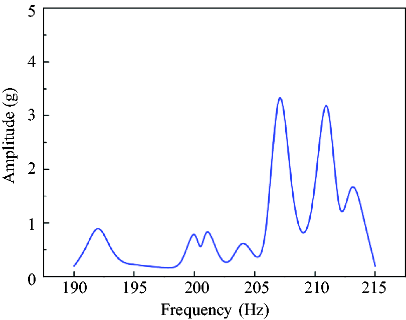
The “frequency–response” curve of blisk.
The resonance frequencies of blisk obtained by the test.
Vibration response test
Here, the vibration response to be measured refers to the vibration response of each calibrated point on blisk. Therefore, in order to complete the vibration response test, it is necessary to apply the corresponding order of the traveling wave excitation to blisk. The vibration responses of blisk under 0th, 1st, 3rd, and 6th order traveling wave excitations were tested, respectively.
Taking the 1st nodal diameter vibration response test as an example, the test procedure is explained as follows. During the 1st nodal diameter vibration response test, it is necessary to apply 1st order traveling wave excitation to blisk and keep blisk in a stable resonant state. Firstly, two accelerometers are attached to two outermost circle adjacent measuring points of blisk. The waveform type, excitation frequency, signal phase, and sampling frequency are set as sine wave, 200.5 Hz, 30°, and 5000 Hz respectively in the signal generator. The impact testing parameter settings can be conducted in data acquisition analyzer. Then, fixing frequency traveling wave excitation is applied to blisk by magnetic exciters. The vibration response of all measuring points of blisk is obtained according to the proposed method.
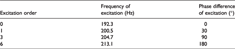
Similarly, for the other order vibration response tests, it is necessary to modify the excitation frequency and the phase of signal to complete all the resonant response tests. The corresponding parameter settings in the signal generator are shown in Table 5. The vibration response time-domain signals of No. 1, No. 2, and No. 3 measuring point under 0th, 1st, 3rd, and 6th order traveling wave excitation are shown in Figures 17–20, respectively.
The corresponding parameter settings in the signal generator.
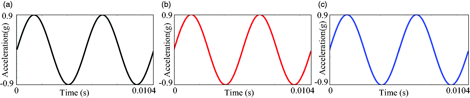
Time-domain signals of blisk under 0th-order excitation (phase = 0°): (a) No. 1 blade; (b) No. 2 blade; (c) No. 3 blade.
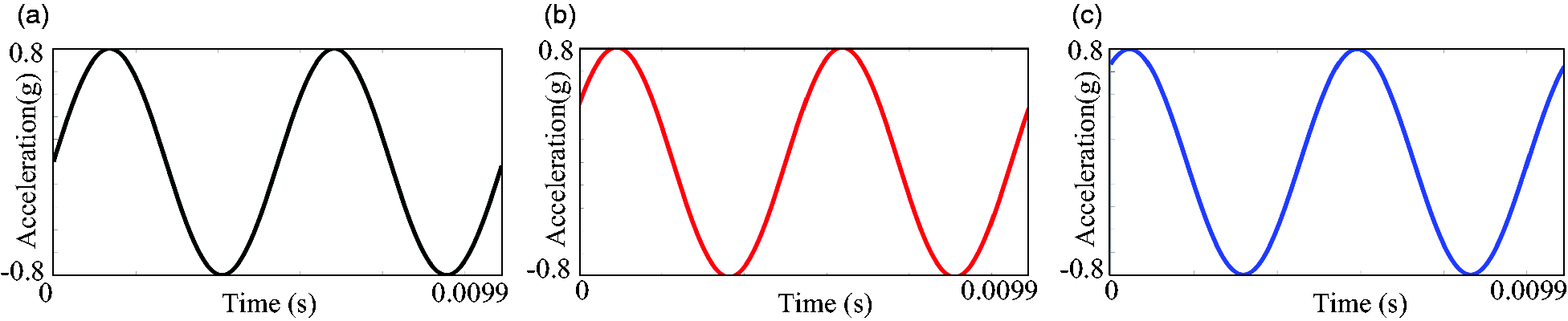
Time-domain signals of blisk under 1st-order excitation (phase = 30°): (a) No. 1 blade; (b) No. 2 blade; (c) No. 3 blade.
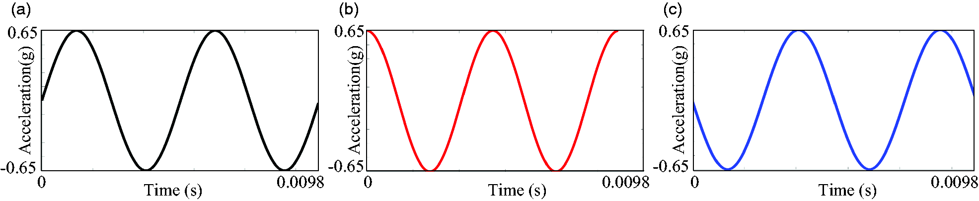
Time-domain signals of blisk under 3rd-order excitation (phase = 90°): (a) No. 1 blade; (b) No. 2 blade; (c) No. 3 blade.
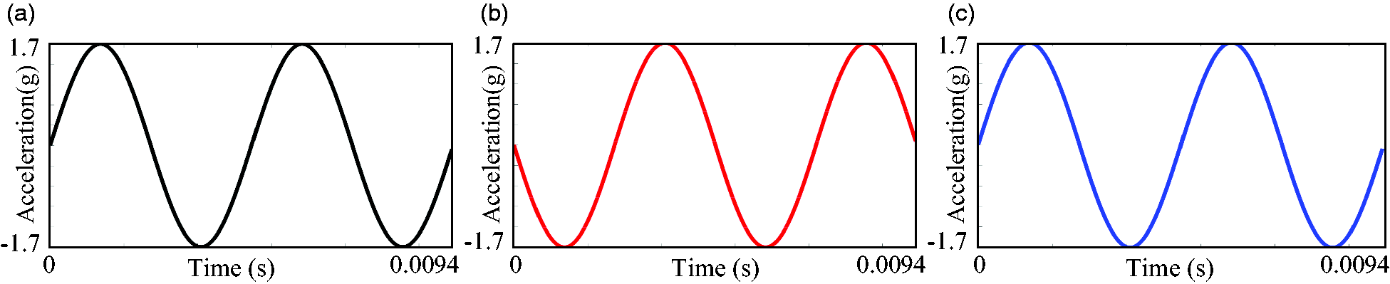
Time-domain signals of blisk under 6th-order excitation (phase = 180°): (a) No. 1 blade; (b) No. 2 blade; (c) No. 3 blade.
Identification of nodal diameter shape and nodal diameter vibration parameters
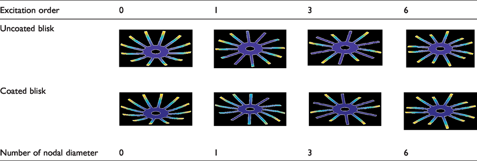
According to the method proposed in an earlier section, the amplitudes at different moments of the outermost circle measuring points of blisk under traveling wave excitation can be expressed as a harmonic form. At one moment, the resonant response amplitude can be regarded as the spatial position of each measuring point. Nodal diameter shapes can be obtained by loading the amplitude of each measuring point into the blisk geometry model (shown in Figure 10). In Table 6, the nodal diameter shape identification results are listed and shows good agreement with the FEA results.
The nodal diameter shape identification results of blisk.
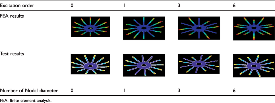
FEA: finite element analysis.
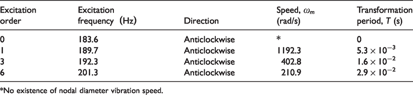
According to the formulas proposed in an earlier section, all the nodal diameter vibration parameter identification results of blisk can be obtained, as listed in Table 7.
The parameters identification results of the nodal diameter vibration for blisk.
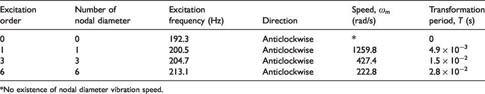
*No existence of nodal diameter vibration speed.
According to results above, it can be seen that the phenomenon of the nodal diameter vibration are obvious. In addition, the nodal diameter shapes of blisk obtained by the proposed method matched well with modal shapes obtained by the FEA. The parameters, which include D, T, and
Characteristics comparison between uncoated blisk and coated blisk
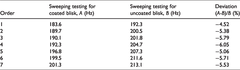
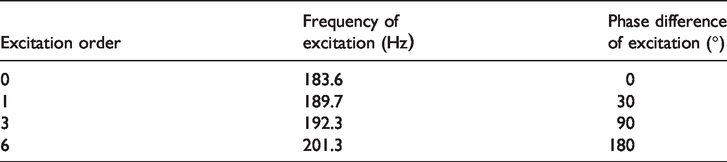
In the previous section, the nodal diameter vibration tests of uncoated blisk were completed. Here, the same tests were performed for coated blisk. Firstly, the resonance frequencies of coated blisk are obtained and listed in Table 8. Then, different order traveling waves excitation are applied to coated blisk. The corresponding parameter settings in the signal generator are shown in Table 9. Vibration response of No. 1 measuring point between uncoated blisk and coated blisk are compared and the results are shown in Figure 21. Next, the nodal diameter shapes of coated blisk are identified based on time-domain signals and shown in Table 10. Finally, the parameter identification of the nodal diameter vibration for coated blisk is performed and the results are shown in Table 11.
The resonance frequency results of coated blisk.
The corresponding parameter settings in the signal generator.
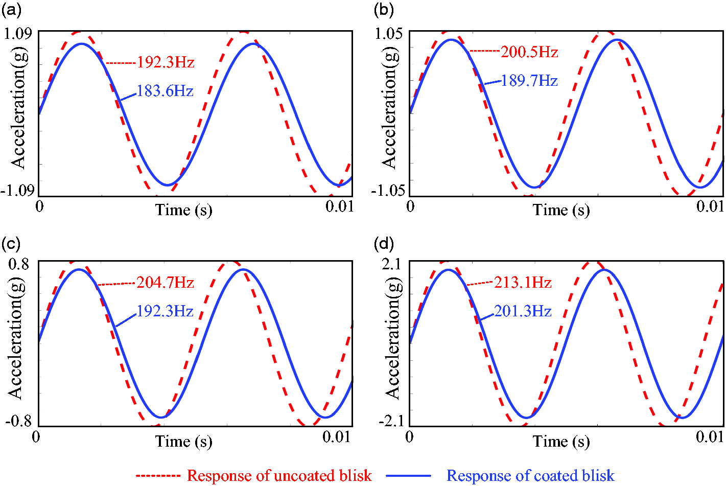
Vibration response comparison of No. 1 measuring point between uncoated blisk and coated blisk: (a) 0th order; (b) 1st order; (c) 3rd order; (d) 6th order.
The nodal diameter shape identification results of coated blisk.
The parameters identification results of the nodal diameter vibration for coated blisk.
*No existence of nodal diameter vibration speed.
It can be seen from results above that both of uncoated blisk and coated blisk have obvious phenomenon of the nodal diameter vibration. Compared with uncoated blisk, the nodal diameter shapes and the nodal diameter vibration direction D of coated blisk are kept constantly. However, the nodal diameter vibration speed
Conclusions
In this paper, based on the resonant response under traveling wave excitation, a novel identification method of the nodal diameter vibration for blisk was proposed. The relevant conclusions are listed as follows.
The phenomenon of the nodal diameter vibration of blisk was described in detail. For describing the nodal diameter vibration quantitatively, three parameters are determined: nodal diameter motion direction D, nodal diameter motion speed A traveling wave excitation system was developed for blisk with the use of noncontact magnetic excitation. The system was equipped with NI-9263 analog output modules to produce 12 channels phased excitation simultaneously. The parameters of each excitation signal can be controlled through the signal generator software developed by LabVIEW. The identification method of the nodal diameter vibration for blisk was proposed based on the resonant responses. The resonant response amplitudes of measuring points are regarded as their spatial position when blisk is in the resonant condition. The nodal diameter shapes can be obtained by loading resonant response amplitudes into the blisk geometric model. The nodal diameter motion direction D is determined by the serial number change order of the blade with 0 amplitude. The nodal diameter vibration speed The identification process of the nodal diameter vibration was performed for uncoated blisk and coated blisk. Then, resonance frequencies, vibration responses, nodal diameter shapes, and parameters of nodal diameter vibration were compared respectively. The comparison results showed that resonance frequencies and vibration responses of coated blisk were reduced because of the coating introduction, but the nodal diameter shapes were almost unchanged. In addition, the nodal diameter vibration speed
Footnotes
Declaration of conflicting interests
The author(s) declared no potential conflicts of interest with respect to the research, authorship, and/or publication of this article.
Funding
The author(s) disclosed receipt of the following financial support for the research, authorship, and/or publication of this article: This work was supported by the National Natural Science Foundation of China (Grant No. 51775092) and the Fundamental Research Funds for the Central Universities of China (Grant No. N180312012).