
Abstract
In the damping design of blisks with hard coating, changing coating thickness is one of the frequently used ways for achieving better damping performance. Nevertheless, for the vibration analysis with variable coating thickness by using commercial finite element software, it is necessary to regenerate the finite element mesh, which results in inconvenience in computation. In this paper, a new laminated element is developed to solve this problem, which needs solely the node coordinates corresponding to the maximum coating thickness. The additional virtual layers to simulate the variations of coating thickness are introduced for the presented element to avoid regenerating new node coordinates. By comparing the analysis results obtained by SOLID185 in ANSYS software, experiment and the developed element, this new element is verified that it remains effective for variable coating thickness parameter input. Furthermore, the effects of the coating thickness on the natural frequency and the forced response of an actual blisk are analysed and due to using the same node coordinates, the computational efficiency is improved significantly. The analysis results indicate that with the increase of coating thickness, the resonance response is reduced significantly and even the thinner coating could also achieve better damping performance.
Keywords
Introduction
Because of the blades and the disk being made of one piece, blisks can improve the thrust-to-weight ratio significantly and has been used widely in aeroengine. 1 Due to lack of the friction damping like traditional bladed disks,2,3 the blisk is easily resonated under the broadband excitation from aerodynamic loads, mechanical loads and temperature field, resulting in fatigue damage in aeroengine applications.4,5 Therefore, it is necessary to minimise the excessive vibration of blisk in the design process.
Many studies have reported the approaches to enhance the damping of blades, such as friction dampers, 6 piezoelectric materials,7,8 passive surface treatments 9 and active magnetic bearings. 10 These methods are effective in increasing the resistance of blisks against vibrations. At present, a new passive surface treatment technique using hard-coating damping has been presented due to its perfect performance to improve surface wear resistance by increasing surface hardness11–13 and reduce the vibration stress of structures in high temperature and corrosion environment.14,15 Even the coating spraying technology could also have an effect on the coating damping property, and the smart adhesion 16 could be used to improve its performance when microscopic characteristics of coating are studied. Thus, hard-coating damping technology is applied widely.
Over the past decades, the modelling methods for blisks mainly include lumped-parameter model,17–21 continuous parameter model,22,23 and high-fidelity finite element model (HFEM).24,25 In general, the lumped-parameter model and the continuous parameter model (containing the FEM and analytical model simultaneously) for simplified blisks could not capture the real characteristic of actual blisks 9 and are only used for researching the mechanism. In contrast, the HFEM is usually used to obtain the reasonable result in industrial applications. However, an HFEM could contain thousands of degree of freedoms (DOFs), which requires expensive calculation. Therefore, many scholars use model reduction techniques such as SNM (Subset of Nominal Modes), 26 FMM (Fundamental Mistuning Method), 27 CMM (Component Mistuning Method), 28 AMM (Asymptotic Mistuning Model) 29 and N-PRIME (New Rogue Interface Modal Expansion) 30 to obtain the analysis model to study the vibration characteristics of blisks. These Reduced Order Models can improve the efficiency for vibration response analysis significantly.
Due to the high-damping performance of hard coating, many researchers have studied the applications of hard coating on simple structures recently, such as beams, plates and shells.31–34 A few of studies35–37 researched the HFEM and the vibration characteristics of hard-coating blisks. These tentative researches are of great significance for reducing the vibration level of blisks and improving their working life. However, in the above-mentioned researches including the modelling method of uncoated blisk, the stiffness and mass matrices were usually obtained from the commercial finite element software such as ANSYS. It should be noted that in the coating damping design of blisks, it is especially essential to vary the coating thickness to improve damping performance. When the coating thickness is changed in commercial finite element software to solve the new stiffness and mass matrices, the finite element mesh of coated blisk needs to be restructured. It is exceedingly inconvenient in the damping design process and will be specifically described in Disadvantages of vibration analysis for coated blisk based on ANSYS section. Therefore, to study the modelling method for blisks with variable coating thicknesses is of great significance.
The aim of this paper is to develop a new FEM of hard-coating blisks. By introducing the additional virtual layers, this new FEM can be used to incorporate variable coating thickness in the damping design process. Some modelling methods for changing the coating thickness on blades are given by using ANSYS, and the disadvantages of using the commercial software to perform the damping design of blisks are also presented in the next section. Then, the FEM of a hard-coating blisk is established based on the presented three-dimensional eight-node incompatible laminated element (named as LI-SOLID element). This is followed by a section in which the dynamic analysis method of the coated blisk is given. In Model verification and application section, the rationality of the created model is verified by ANSYS software and experiment. The advantage of the LI-SOLID element is also demonstrated. Finally, some important conclusions are listed.
Disadvantages of vibration analysis for coated blisk based on ANSYS
The commercial finite element software ANSYS is a powerful tool to dynamics analysis of many structures. However, it could be very inefficient to solve stiffness and mass matrices when the coating thickness is changed in the damping design process of hard-coating blisks. In this section, we only introduce two methods to simulate the coated blisk with variable coating thickness.
For the first method, the laminated element SOLID185 is used to simulate the coated blades as shown in Figure 1. Note that the element number of a single blade is 165, with the nodes number being 384. When the coating thickness is changed, the finite element mesh needs to be manually regenerated. In this way, the nodes coordinates of the coated blades and those of the disk connected to the coated blades must be changed simultaneously as shown in Figure 1.
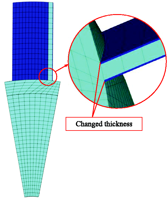
Laminated FEM with SOLID185.
For the second method35,38 shown in Figure 2, the coated blade is divided into three layers elements of SOLID185. Then, the element number of a single blade is 495, with the nodes number being 768. The problem similar to the first method still exists when coating thickness is changed.
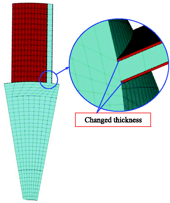
FEM with three layers elements of SOLID185.
Although the element number of the first method is less than the second one, the two methods based on ANSYS software are also computationally expensive for vibration damping design of blisks with coating. There may be other modelling methods we have not introduced, but the problem could be same as the above-mentioned methods when the commercial software is used. So it is essential to develop a composite element for coated blisks to satisfy the requirement of variable coating thickness, which can be conducive to vibration reduction techniques using hard coating.
FEM of coated blisk
In this section, we present a new laminated incompatible solid element, named as LI-SOLID element, to derive the stiffness and mass matrices for the blisk with hard coating on blades as shown in Figure 3(a). This element is similar to SOLID185 in ANSYS, with eight nodes and three DOFs of each node as shown in Figure 3(b), and Figure 3(c) is the element sector of coated blades. However, it does not need to restructure the finite element mesh when coating thickness is changed, which could improve the computational efficiency in the design process with coating.
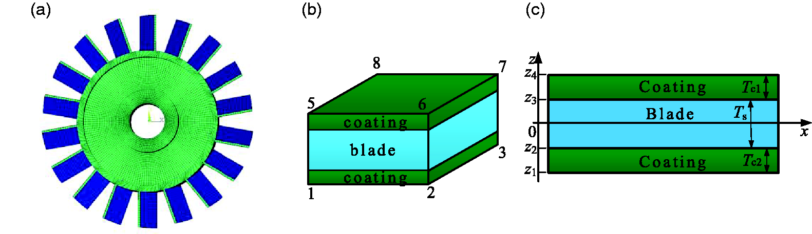
FEM of the coated blisk. (a) Coated blisk, (b) LI-SOLID and (c) element sector of coated blade.
Stiffness and mass matrices
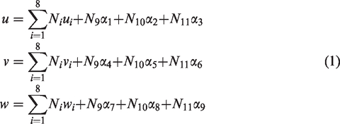
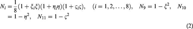
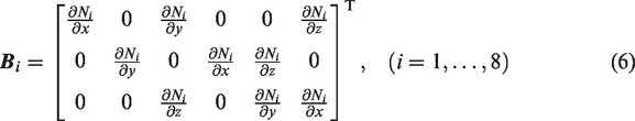
The LI-SOLID element introduces nine additional DOFs, with being eliminated by static condensation while calculating the stiffness matrix. Therefore, it could avoid the shear-locking effect of compatible element and not increase the DOFs of the system. The corresponding displacements for an arbitrary point in the LI-SOLID element can be described as
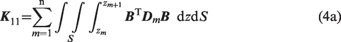
For a composite structure with n layers, the block static equilibrium equation can be expressed as
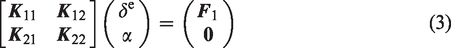


Then, with static condensation to eliminate the additional DOFs

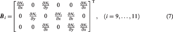
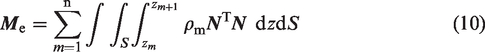
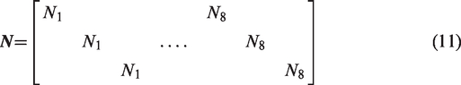
It should be noted that the mass matrix of the LI-SOLID element is obtained by the shape function of the compatible one, which is expressed as
In order to use the Gauss rule for each layer conveniently in equation (4) and equation (10), the coordinate transformation of the mth layer is employed and is given by


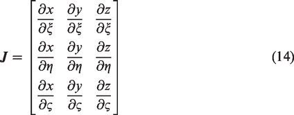
Note that the Jacobian matrix should use
Application method of the LI-SOLID
The application method of the LI-SOLID element would be introduced in detail for coated blades and the uncoated disk of blisks. Note that the developed modelling method can be used to any actual coated blisk where the blades are uncoupled. It needs only the element node coordinates corresponding to the maximum coating thickness, and even the thickness of the blades is smaller, it only needs to increase the number of elements.
In this work, Figure 4(a) shows the coated element with the thickest coating. With the thickness of the coating being changed, it only needs to divide the above-mentioned lamination element into five layers as shown in Figure 4(b). Here, the third layer represents the substrate of blade, and the second and fourth layers represent the hard coating, with the fifth and first layers being considered as the virtual layers. By setting the Young’s modulus, the density and other material parameters of the virtual layers to 0, the new stiffness and mass matrices can be recalculated quickly when coating thickness is changed. Even the coating thickness is 0, the LI-SOLID element can also be used here by setting the material parameters of the first, second, fourth and fifth layers to 0. Note that for the variable coating thickness, it only needs to change the thickness values of each layer in equation (12) under local coordinate, which do not need to regenerate the finite element mesh manually. In this way, if the coating thickness is random, the method is also suitable, and the efficiency of the solution can be significantly improved due to avoiding a re-meshing process.
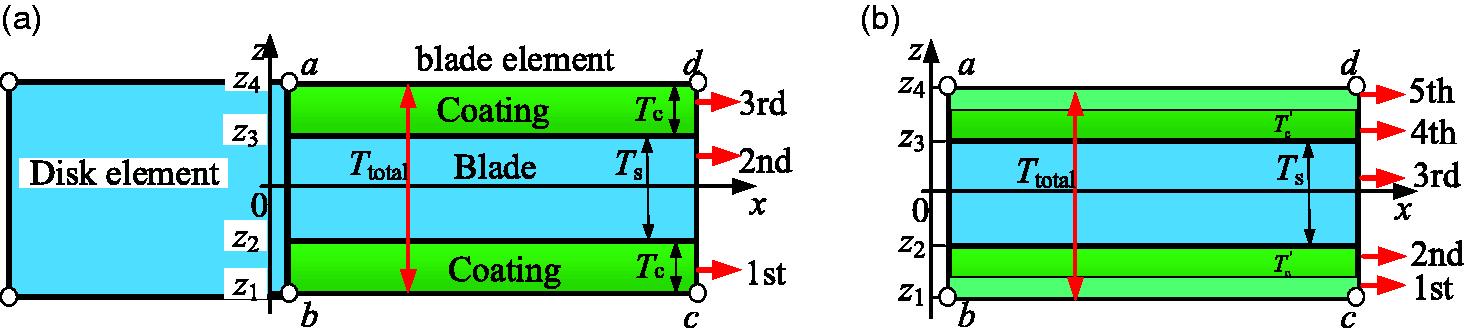
Sector of LI-SOLID element. (a) With the thickest coating and (b) with the variable coating thickness.
For the uncoated disk, the element without hard coating is just a special case of the three-layered LI-SOLID element, as it only needs to set the Young’s modulus, the density and other material parameters of all layers to the same one.
Therefore, the developed element is comparatively more convenient to simulate the coated blisk with the variable coating thickness and could improve the computational efficiency significantly.
Analysis method of coated blisk
Equations of motion
The forced vibration equation in frequency domain of a blisk with hard coating on blades can be expressed as

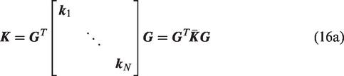
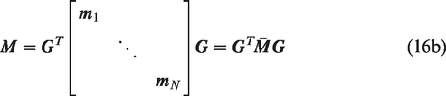
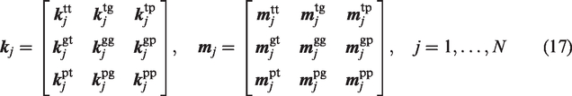
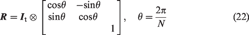
For a blisk, the system stiffness and mass matrices can be represented by those of N sectors, given by
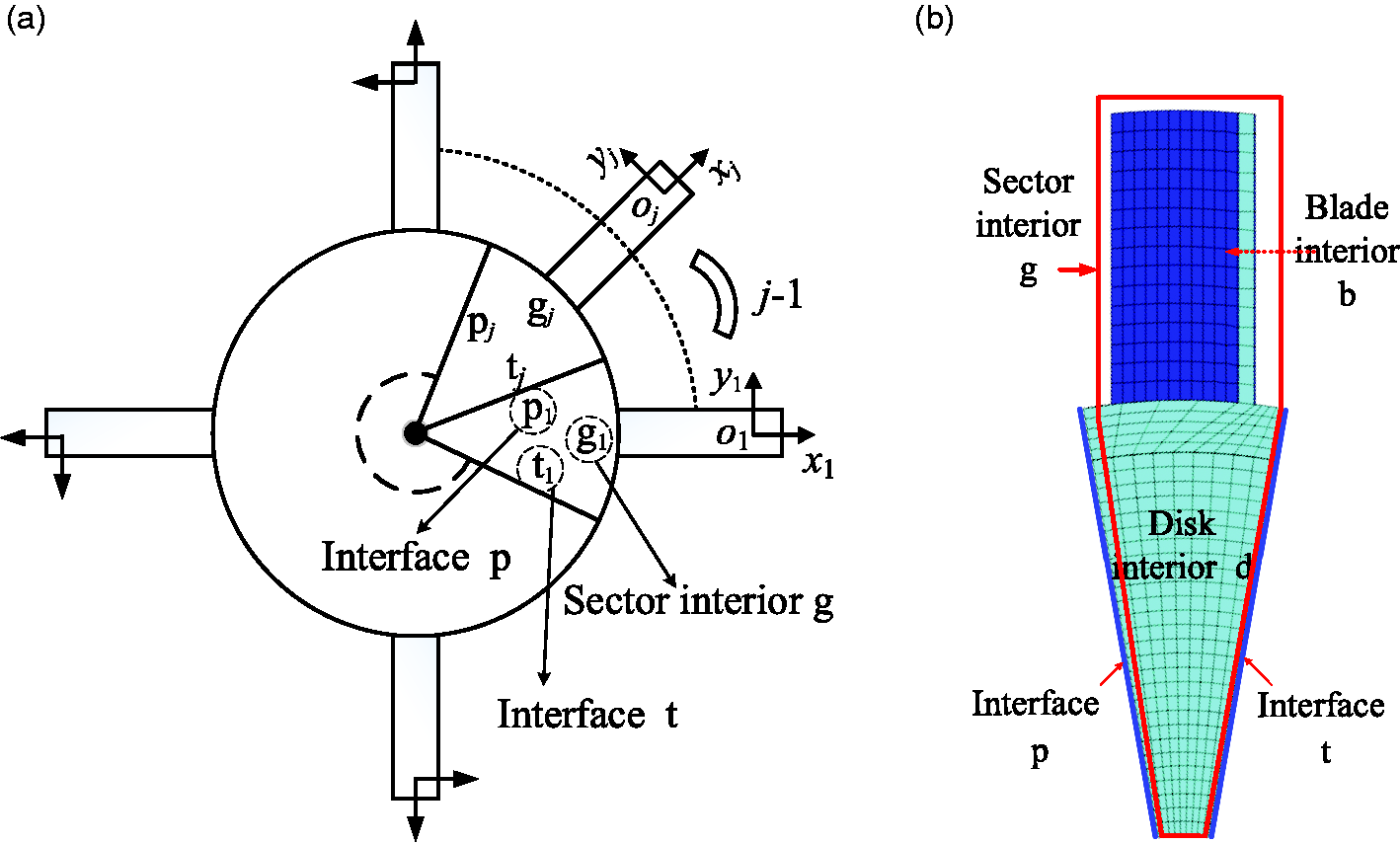
Local Cartesian coordinate systems of the blisk.
To obtain the structural system matrix


The displacement coordination relationship between the expanded displacement vector and the real displacement vector can be expressed as
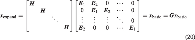
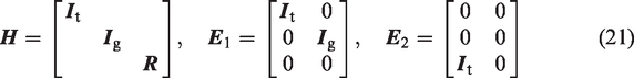
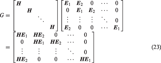
Then, the specific expression for the assembly matrices
Forced response analysis
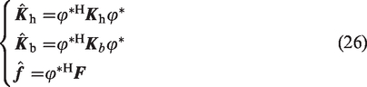
For a single sector with variable coating thickness, the stiffness matrix

Furthermore, the truncated mode matrix
By multiplying

Furthermore, the forced response in frequency domain of the blisk subjected to engine order (EO) excitation can be obtained by the classic mode superposition method. Note that the above-mentioned matrices are all sparse matrices.
Model verification and application
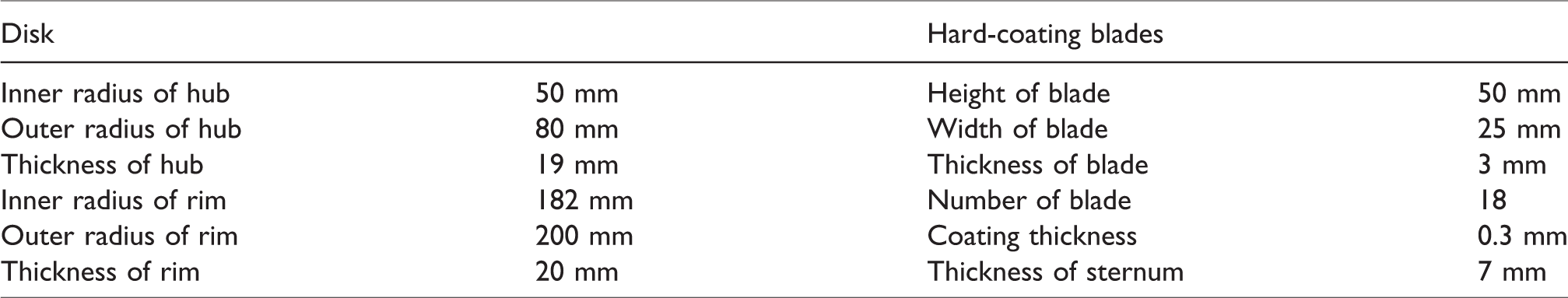
In this work, an actual blisk attached with hard coating on both sides of each blade is used to verify the developed modelling method. The geometric parameters of the vibration model used in this section are listed in Table 1, and the boundary constrains are shown in Figure 6. In order to avoid excessive additional mass and ensure better damping performance, a range of 0–0.3 mm for coating thickness is used, i.e. the maximum thickness of coating is 0.3 mm (10% of blade thickness).
Geometrical parameters of the blisk and hard coating.
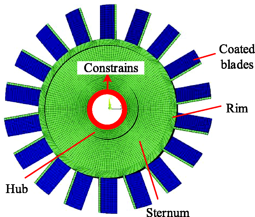
Vibration model of the coated blisk.
Description of the experimental test
Here, an experimental test for a steel blisk with 0.3 mm coating on both sides of each blade is used to verify the modelling method based on ANSYS in literature35,38 (the method was also described in Disadvantages of vibration analysis for coated blisk based on ANSYS section) and the developed method. It should be noted that the steel blisk is usually used in reported researches.
The Young’s modulus, the density, the loss factor and the Poisson’s ratio of the Q235-A(F) steel blisk are 208 GPa, 7860 kg/m3, 0.0004 and 0.28, respectively, and those of the coating material NiCoCrAlY + YSZ are 54.45 GPa, 5600 kg/m3, 0.0212 and 0.3, respectively. Figure 7 shows the hard-coating blisk. Then, the natural frequencies obtained by experimental test, the modelling method based on ANSYS and the developed method are listed in Table 2.
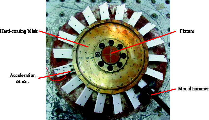
Hard-coating blisk.
Natural frequencies and relative differences.
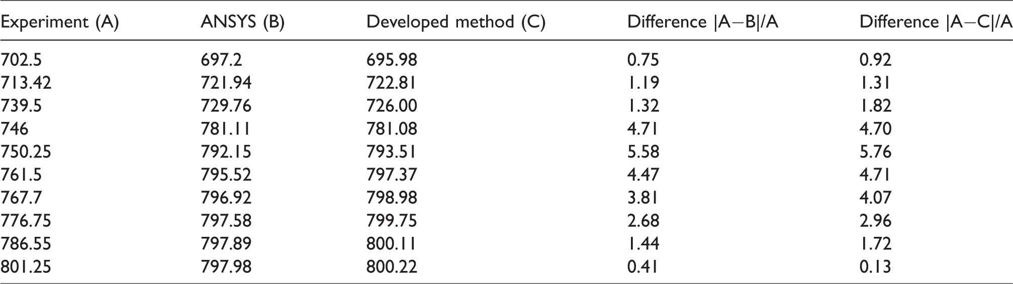
The results show that the maximum difference between the results obtained by experiment and ANSYS for the coated blisk is 5.58%. And the one between the results obtained by experiment and the developed modelling method is 5.76%. In that way, it can be concluded that the modelling method in literature35,38 and the developed method could be used to calculate the vibration characteristics of the coated blisk.
Verification of the developed modelling method
In practice, the blisk made of titanium material is widely used in aeroengine and its modelling method needs to be focus on. Since the blisk made of titanium material has not yet been obtained in the study, so only a titanium blisk attached with hard coating on both sides of each blade is used to verify the developed LI-SOLID element.
For titanium material, the Young’s modulus is 103.213 GPa with the density being 4200 kg/m3, the loss factor being 0.0007 and Poisson’s ratio being 0.33. In addition, the coating material is also NiCoCrAlY+YSZ and its thickness is 0.3 mm.
Two verification cases are analysed. It should be noted that the element and node number are 32778 and 46800, respectively, for the FEM by applying LI-SOLID element, and those for the FEM by applying SOLID185 in ANSYS software are 38728 and 53712, respectively.
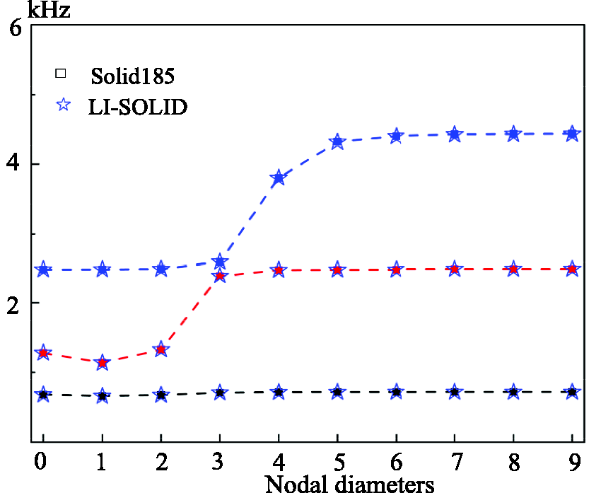
For case 1, the LI-SOLID element is used to solve the natural frequencies and the forced responses subjected to EO excitation for the tuned coated blisk. Figure 8 shows the natural frequencies sorted with nodal diameters (NDs) obtained by the developed LI-SOLID element model solved in MATLAB and the HFEM using three layers SOLID185 in ANSYS. Here, only the first three orders frequencies of ND 3 and 6 are listed in Table 3. Note that the EO excitation is applied to the z direction of the tip nodes of each blade, and the pick-up points are same to the excitation points. The forced responses subjected to three EO and six EO excitations are also obtained based on the above two elements, and the relevant results are shown in Figure 9(a) and (b), with the resonance responses being listed in Table 4. Note that for the tuned blisk, the forced responses of each pick-up point are exactly the same.
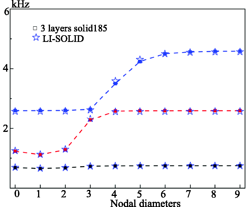
Natural frequencies for the coated blisk.
First three orders frequencies of ND 3 and ND 6 for the coated blisk (Hz).
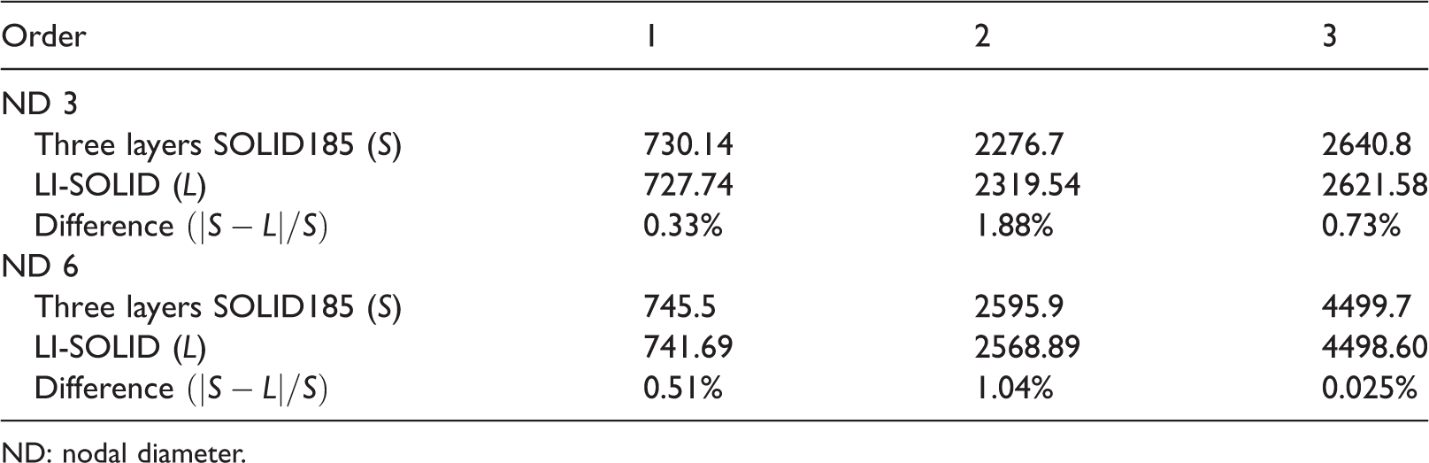
ND: nodal diameter.
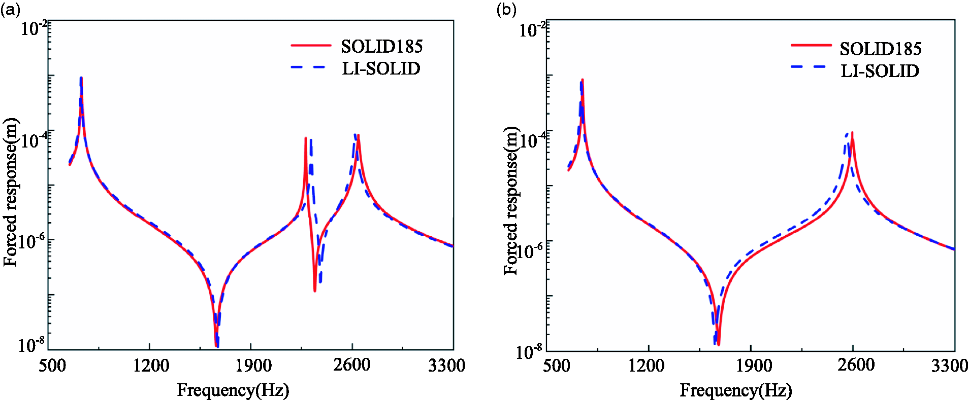
Forced responses with coating. (a) Forced responses under three EO excitations and (b) forced responses under six EO excitations.
Resonance response under three EO and six EO excitations for the coated blisk (m).
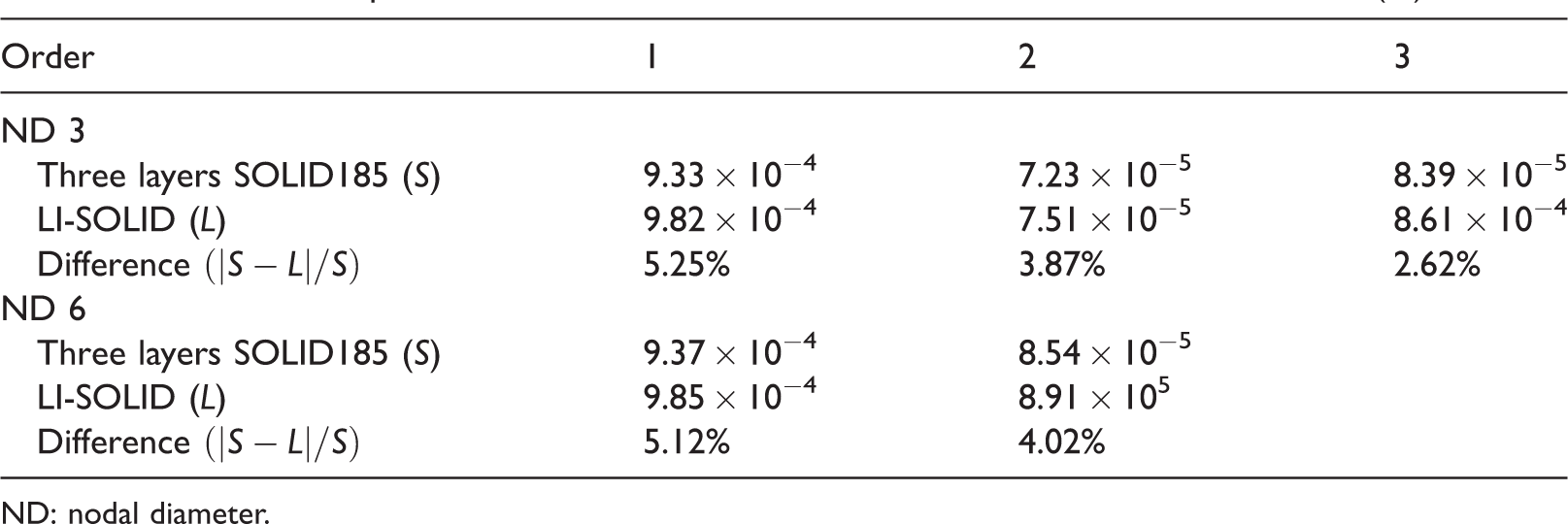
ND: nodal diameter.
It can be seen that the maximum difference of natural frequencies is 1.88% for the modelling methods using the LI-SOLID and SOLID185 in ANSYS software. For the resonance responses, the maximum difference is 5.25%. So the presented element can be used to solve the vibration characteristics of coated blisks.
For case 2, the natural frequencies and the forced responses for the uncoated blisk are solved by the developed modelling method and the above-mentioned methods based on ANSYS software. The relevant results are shown in Figures 10 and 11 and Tables 5 and 6. Note that the pick-up points and the excitation points are same to case 1.
Natural frequencies without coating.
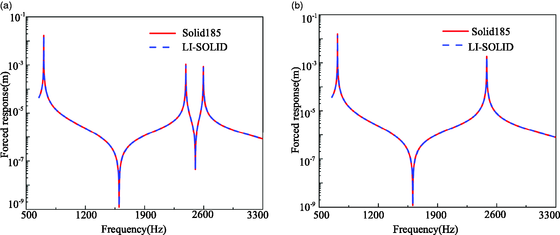
Forced responses for uncoated blisk. (a) Forced responses under three EO excitations and (b) forced responses under six EO excitations.
First three orders frequencies of ND 3 and ND 6 for the uncoated blisk (Hz).
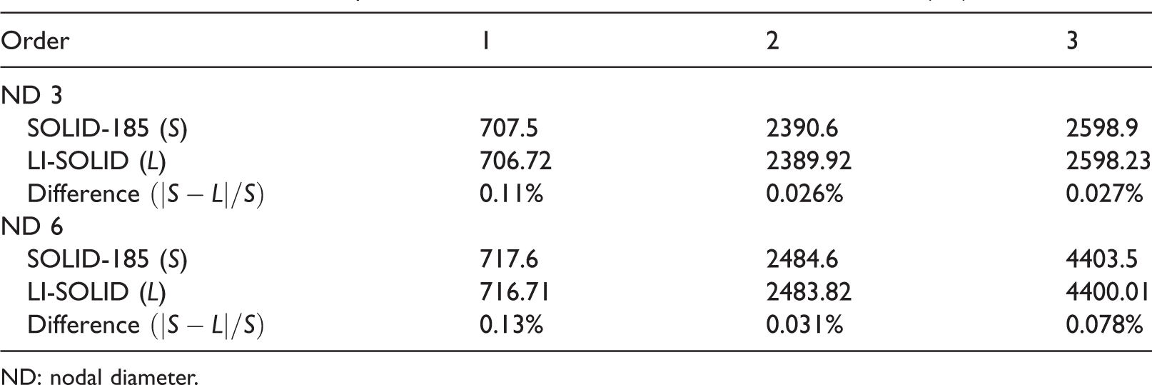
ND: nodal diameter.
Resonance responses under three EO and six EO excitations for the uncoated blisk (m).
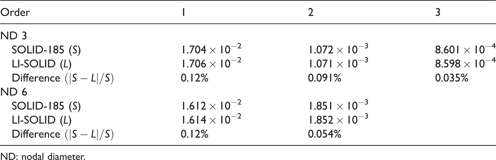
ND: nodal diameter.
The results indicate that both the natural frequencies and the forced responses for the modelling method using the LI-SOLID element are in good consistency with those using SOLID185. Note that using the LI-SOLID element to obtain the vibration characteristics for the uncoated blisk is equivalent to change the maximum coating thickness from 0.3 mm to 0 mm, which can be considered as a special case of changing the coating thickness.
Therefore, it can be concluded that the LI-SOLID element can be used to simulate the variable coating thickness.
Model application
An exhaustive research is conducted to obtain the effect of different thicknesses of coating on the forced response. First, the stiffness and mass matrices for the tuned coated blisk with 0.3 mm coating on blades can be solved by the presented LI-SOLID element. When the coating thickness is changed, the new stiffness and mass matrices of blisk can be resolved by the LI-SOLID element. Note that here by using the LI-SOLID with the virtual layers as shown in Figure 4(b), the finite element mesh does not need to regenerate, and we only need to change the thickness values of each layer in equation (12) under local coordinate. Then, the method described in Analysis method of coated blisk section can be used to obtain the forced response. But with the coating thickness being changed in ANSYS software, it needs to regenerate the finite element mesh, which can be very inconvenient and result in an inefficient computation in in the process of damping design. Herein, only the uniform change of the coating thickness for each blade is analysed.
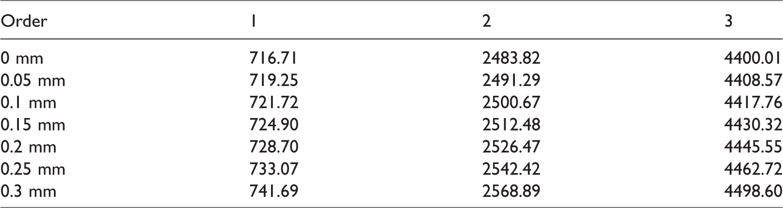
The variable coating thicknesses are 0 mm, 0.05 mm, 0.1 mm, 0.15 mm, 0.2 mm, 0.25 mm and 0.3 mm. Tables 7 and 8 list the obtained natural frequencies of ND 3 and ND 6. Figures 12 and 13 show the obtained forced responses under three EO and six EO excitations, with the resonance responses being listed in Tables 9 and 10.
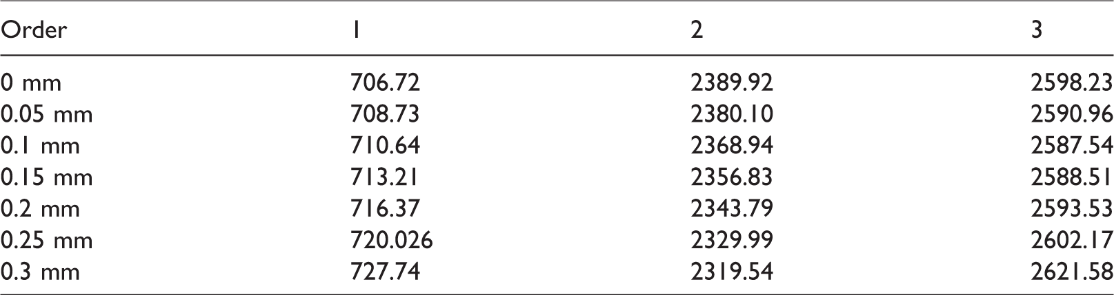
First three orders frequencies of ND 3 with the variable coating thicknesses (Hz).
First three orders frequencies of ND 6 with the variable coating thicknesses (Hz).
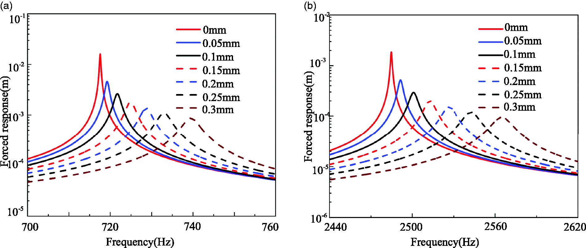
Forced responses for coated blisk under three EO excitations (m). (a) Forced responses containing the first order and (b) forced responses containing the second and third order.
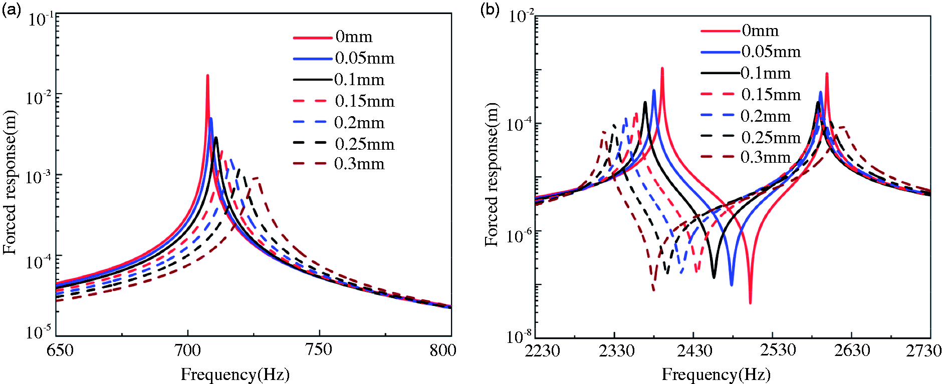
Forced responses for coated blisk under six EO excitations. (a) Forced responses containing the first order and (b) forced responses containing the second order.
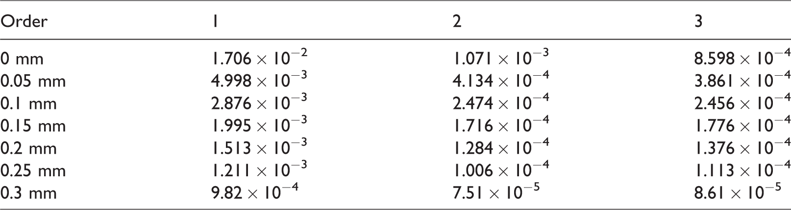
Resonance response of three EO excitations with the variable coating thicknesses (m).
Resonance responses of six EO excitations with the variable coating thicknesses (m).
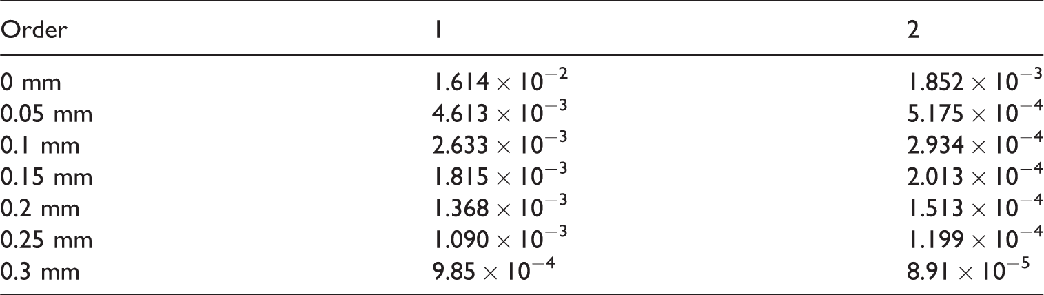
The results listed in Tables 7 and 8 indicate that the natural frequencies for one certain order changed monotonously with the increased coating thickness. For the forced response, with the increase of coasting thickness, the resonance response is reduced. Especially for coated 0.05 mm, the resonance response for the uncoated blisk is reduced sharply. But when the coating thickness exceeds 0.1 mm, the resonance response is reduced a little. In short, the damping properties and the additional mass of the coating should be considered together in the process of damping design.
Conclusion
This paper highlights a new FEM, which can be used to incorporate variable coating thickness in the damping design of coated blisk by introducing the additional virtual layers of the LI-SOLID element. Then, based on the developed element, the effect of different coating thickness on forced response was analysed. Some important conclusions are listed as follows. To simulate the blisk with the variable coating thickness in the damping design, the virtual layers are introduced to the LI-SOLID element and the thicknesses of each layer can be changed by the coordinate transformation under local coordinate. With the material parameters of the virtual layers being setting to 0, the new stiffness and mass matrices can be solved without regenerating the finite element mesh. Compared with the natural frequencies and forced responses obtained by the HFEM in ANSYS, the presented LI-SOLID element is verified that it can be used to improve the computational efficiency with variable coating thickness. For the blisk with the maximum coating thickness, the results between the developed method and the one in ANSYS software show that the maximum natural frequencies difference is 1.88% and the maximum difference of the resonance responses 5.25%. With the increase of coating thickness, the natural frequencies for one certain order changed monotonously and the forced response is reduced significantly. Even the thinner coating could also achieve better damping performance. The damping properties and the additional mass introduced by the coating should be considered together in the damping design process with coating.
Footnotes
Declaration of conflicting interests
The author(s) declared no potential conflicts of interest with respect to the research, authorship, and/or publication of this article.
Funding
The author(s) disclosed receipt of the following financial support for the research, authorship, and/or publication of this article: This work was supported by the National Natural Science Foundation of China (Grant No. 51775092) and the Fundamental Research Funds for the Central Universities of China (Grant No. N180312012).