
Abstract
When two electric multiple units are non-electrically connected together for improving the transport capacity in high-speed railways, double pantographs frequently operate simultaneously to decrease the current capacity on a single pantograph collector. In this case, the contact force between the trailing pantograph and the catenary severely fluctuates due to the wave propagation along the catenary triggered by the leading pantograph. Therefore, this paper proposes two estimator-based H∞ control strategies for active double-pantograph to decrease the contact force fluctuation considering the actuator time delay. To obtain the pantograph states, a robust recursive state estimation method is presented, which can effectively deal with randomly missing measurements. In addition, to overcome parametric uncertainties and non-differentiable actuator time delay, two robust multi-objective H∞ controllers involving linear matrix inequalities are introduced according to whether the time delay can be predetermined or not. The effectiveness and robustness of the control strategies are investigated through implementing a nonlinear double-pantograph-catenary system model. Simulation results show that, for both the leading pantograph and the trailing pantograph, the proposed control strategies can decrease the contact force fluctuation with high efficiency even though the actuator time delay exists.
Keywords
Introduction
For greater economic and social benefits, the electrified railway industry is extensively expanding in many countries. To ensure the steady and safe operation, one of the crucial technical issues is to improve the current collection quality of electric multiple units (EMUs). This quality can be characterized by the contact force between the pantograph and the catenary in general. 1 In other words, the stationarity of contact force should be paid more attention to as the upgrade of running speed.
To improve the transport capacity, especially in China, two EMUs are frequently connected together, which results in a special working condition that double pantographs operate simultaneously due to the restriction of current capacity on the collector strips, 2 as shown in Figure 1. Under this circumstance, the impact of the leading pantograph (LP) on the catenary indirectly affects the trailing pantograph (TP) through the wave propagation. Therefore, the fluctuation of contact force between the TP and the catenary becomes more violent, which leads to many serious problems. To resolve this matter, the dynamic behaviors of double-pantograph-catenary system (DPCS) have been deeply investigated.3–5 Many feasible measures were then proposed, such as applying different lift force on the LP and TP, 3 adopting appropriate pantograph intervals, 4 and optimizing or renovating the pantograph-catenary system (PCS), 2 but they are of limited usefulness or involve considerable economic costs. This paper attempts to overcome this challenge through active control of the double-pantograph based on our previous works,6,7 which has been explored in the single-pantograph-catenary system.8–19
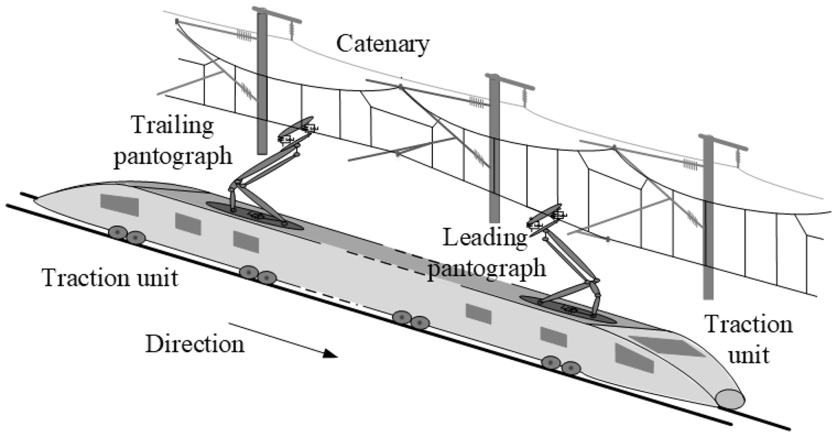
Sketch of double-pantograph-catenary system in high-speed railway.
In recent years, many controllers were developed for the active pantograph, such as Proportion Integration Differentiation (PID) control,8–10 sliding mode control,11,12 optimal control,13,14 fuzzy control, 15 model predictive control, 16 adaptive and robust fault tolerant control, 17 backstepping control, 18 feedforward control, 19 etc. However, the validations of these controllers8–19 were only verified with single pantograph, which might be inefficient with double pantographs due to the more complex structure and higher nonlinearity of the system. Even though the influence of small time delay (5 ms) was slightly discussed, 9 how to overcome greater actuator time delay was not mentioned before. This paper attempts to overcome these challenges. Actuator time delay is a realistic factor that affects the control efficiency in any systems. Generally, there are two possible ways to address this problem. The first one is integrating the actuator model with the controlled plant when designing a controller. 20 The second one is that, to explicitly deal with it, the time delay is regarded as a variable in the design process. Obviously, the latter is independent on different actuators, which is more generalized. Based on this principle, many controllers were proposed by considering the actuator time delay, such as sampled-data control, 21 reliable fuzzy control, 22 multi-objective control, 23 non-fragile static output feedback control, 24 etc. In this paper, based on the state feedback H∞ control framework, the time delay of active pantograph actuator is explicitly considered according to whether it can be predetermined or not. That is to say, the fixed time delay and the random time delay are separately taken into account. Meanwhile, besides the contact force fluctuation, the contact force limitation, as the second objective, is noticed in the proposed controllers, which has been overlooked in this topic.
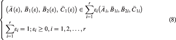
To achieve the best performance of the state feedback control, the pantograph states must be accurately obtained, but it is of difficulty to be realized in a real DPCS plant. On one hand, sensors cannot be installed on the locomotive roof due to some security reasons. On the other hand, due to the complicated electromagnetic circumstance and severe physical environment, the measurements may contain noise and even randomly missing information. For instance, two force sensors, two acceleration sensors, three velocity sensors, and three displacement sensors are required to measure the states of a single collector pantograph. Therefore, inspired by the earlier studies,25–29 the state estimation is introduced in observing the pantograph states. The sensor fault and data loss are also considered in the estimation algorithm. In addition, compared with actual systems, both pantograph and catenary models inevitably have some deviation that has a negative impact on estimation performance. Through the above analysis, a robust recursive state estimation method (RRSEM) is derived for pantographs considering both parametric uncertainties and randomly missing measurements.
Motivated by the above analyses, the main contributions of this paper are as follows: (1) Two estimator-based robust multi-objective state feedback control strategies for active double-pantograph in DPCS are proposed, (2) the actuator time delay is considered in the control strategies based on whether it can be predetermined, and (3) the effectiveness and robustness of the control strategies are investigated in detail with a nonlinear DPCS model.
The study ideas and their relations are shown in Figure 2. Firstly, a nonlinear DPCS model is constructed, and the problem is formulated based on a control-oriented model (COM). Secondly, a robust state estimator is introduced, And two robust controllers are presented, respectively. Then, five cases are carried out to investigate the performance of the control strategies. Some conclusions are drawn in the last section.
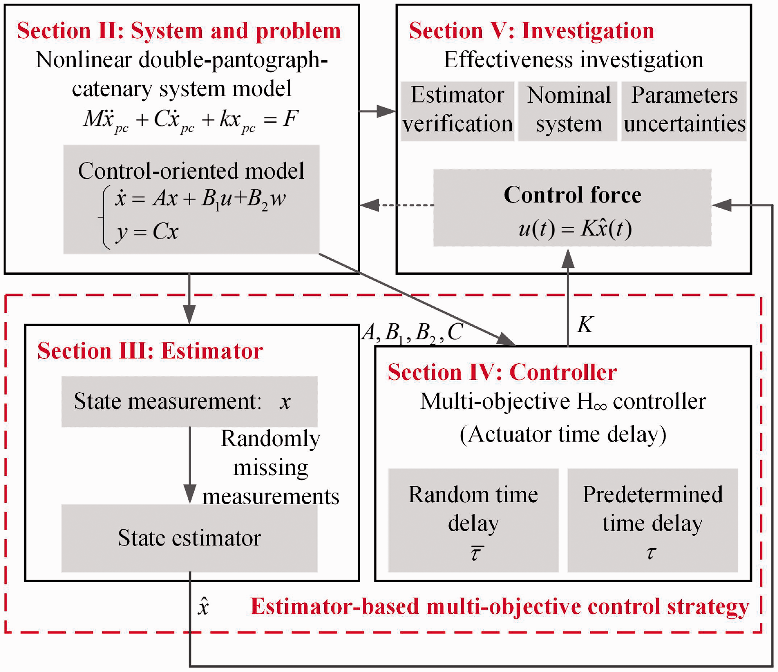
Main ideas and their relations in this study.
Notation
The notations adopted in paper are fairly standard. For a matrix M, MT and M−1 denote its transpose and inverse, and M > 0 denotes M is real symmetric and positive definite. [M]
SYM
denote M + MT. For a variable a,
System model and problem formulation
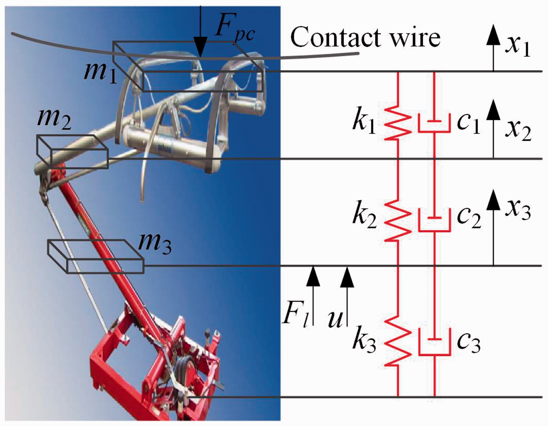
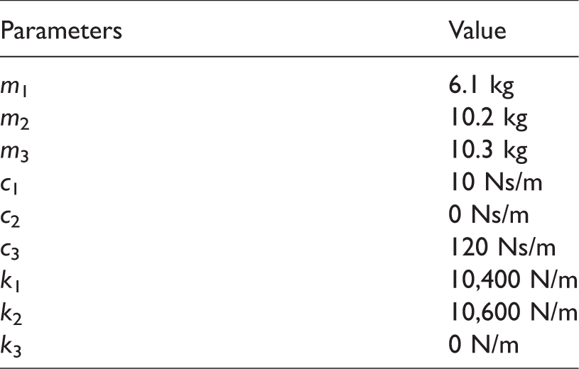
To facilitate the problem formulation and effectiveness investigation, a nonlinear DPCS model is constructed firstly. Without the loss of generality, the SSS400+ pantograph widely used in China high-speed railway network is employed as both the LP and TP. According to the earlier studies,8–19 the pantograph is regarded as a three-stage lumped model, as shown in Figure 3. m1, m2, and m3 denote the equivalent masses of the collector, upper frame, and lower frame of the pantograph. ki (i = 1, 2, 3) and ci (i = 1, 2, 3) denote the damping and stiffness between mass m1 and m2, m2 and m3, and m3 and the base, respectively. The equation of motion can be described with contact force Fpc, static lift force Fl, and control force u as follows
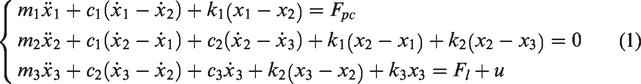
SSS400+ pantograph and its three-level model.
The structure of a real elastic stitched catenary is very complex, as shown in Figure 4(a), which is mainly composed of the contact/messenger wire, stitch wire, and droppers, as shown in Figure 4(b). Its model is established by finite element method (FEM), in which the contact/messenger wire is modeled based on nonlinear cable elements and the droppers are modeled based on nonlinear truss elements, as shown in Figure 4(c) and (d). The structural dynamic of catenary can be given as

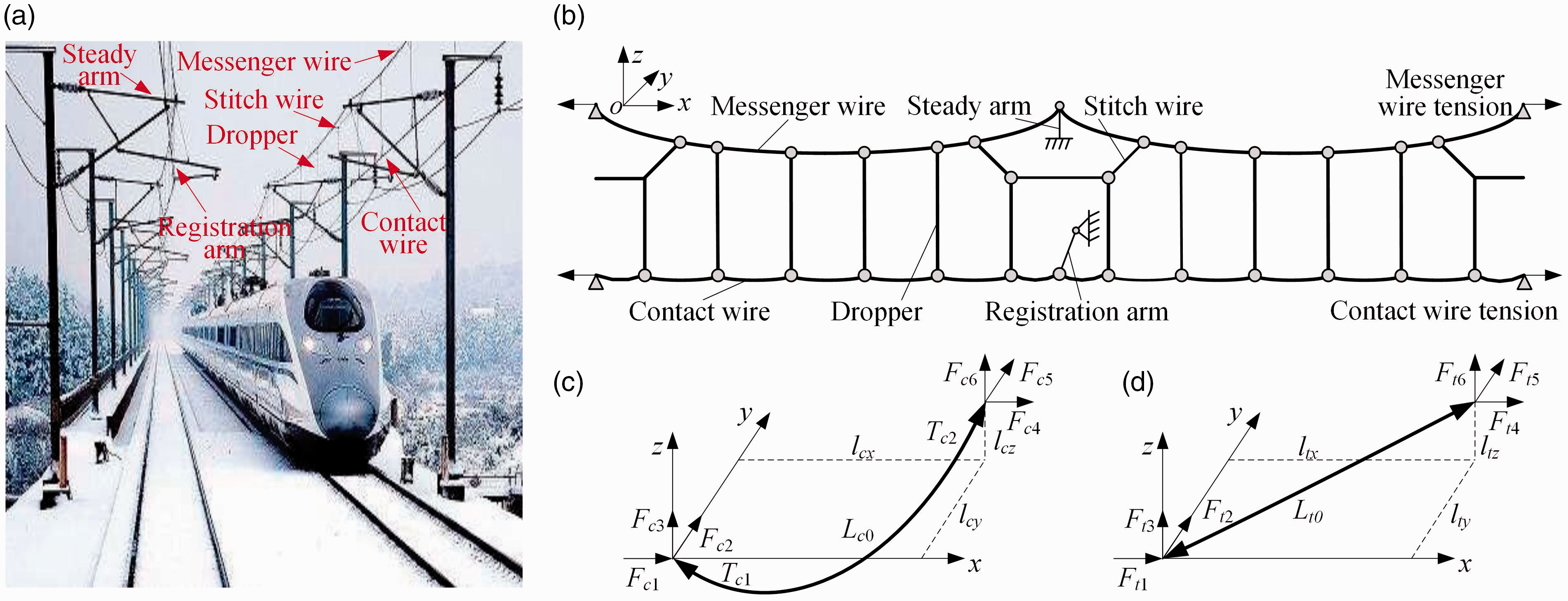
Nonlinear catenary model. (a) Real catenary line, (b) its geometry structure, (c) cable element, and (d) truss element.
Combining equations (1) with (2), the DPCS model can be denoted as

To validate the proposed modeling method, the European Standard EN 50318,30 the SIEMENS simulation reports, 31 and the recent benchmark initiative 32 are adopted as references. The simulation results are shown in the studies by Wang et al. 1 and Song et al., 33 which meet the ranges of the corresponding standards completely.
As shown in the study by Song et al.,
33
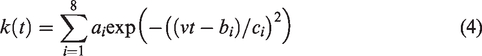
the system model based on the FEM is too complex to be used in controller design. Therefore, a COM is necessary in practice. The key point is that, as the main cause of contact force fluctuation, the unsmooth stiffness distribution along the contact wire should be exactly expressed. It can be described as
Then, combining equations (1) with (4), the contact force is denoted as

To decrease the contact force fluctuation without affecting its mean value, the controller can be designed for reducing the error between the real-time contact force Fpc(t) and its reference value Fr. Therefore, according to equations (1), (4), and (5), the state space model of PCS should be augmented as

Before designing controllers to decrease the contact force fluctuation, the following aspects should be considered.
Actuator time delay. No matter which actuator we choose, its time delay is always unavoidable from the viewpoint of application. To obtain a general conclusion, this problem is addressed according to the value of the time delay instead of indicating a specific actuator; System uncertainties. It is worthy of note that system uncertainties may exist because the accuracy of parametric identification is not guaranteed. In addition, some external conditions, such as icing on link members, can also lead to model mismatch. In fact, parametric uncertainties must be considered in every model-based controller; Maximum control force. An actuator cannot provide the infinite control force in reality. Thus, besides the main target, the control force should be limited in a reasonable range as an application study.
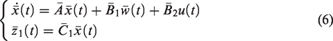
Based on the above analysis, equation (6) is rewritten as

Therefore, the whole problem can be described as to design a state feedback law


State estimation for the pantographs
In general, the process noise exists in any systems and the measured outputs are usually corrupted by measurement noise, such as sampling errors. If the process noise and the measurement noise are denoted as ωk and vk, respectively, the discrete state equation for state estimation can be written as
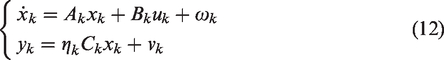

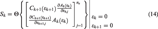
The added stochastic variable ηk in equation (12) is a Bernoulli distributed white sequence taking the value of 0 and 1 with
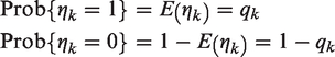
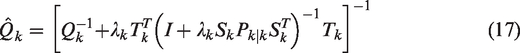
The RRSEM proposed in the study by Zhou 29 is applicable for the system without inputs. Therefore, according to equation (10), the estimation algorithm is improved as follows
INPUT:

FOR k = 1, 2, … , n


FOR

FOR

END
where
Multi-objective controllers considering the actuator time delay
According to whether the actuator time delay can be predetermined or not, two robust controllers for active double-pantograph are presented in this section.
To analyze the advantages of the proposed controllers, a primary controller without considering actuator time delay is presented firstly, which is analyzed in the study by Lu et al. 6
Controller I
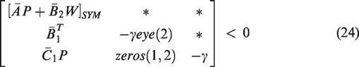
Given the positive scalars γ and ρ, if there are appropriate dimension matrices P > 0 and W that satisfy
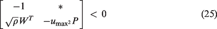
This controller is easy to be proved through choosing a Lyapunov functional candidate as V(x) = xT(t)Px(t). The detailed process is omitted here.
If the actuator time delay denoted as τpd can be predetermined, the following controller presented in the study by Gao et al. 21 for active suspension can be improved and employed as follows.
Controller II
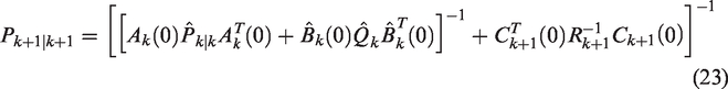
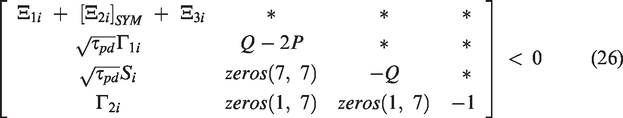
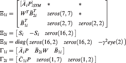
Given the positive scalars γ, τpd, and ρ, if there are real symmetric and positive definite matrices P > 0 and Q > 0, and matrices Si and W that satisfy equation (25) and
Proof: Choose a Lyapunov functional candidate for system (7) with

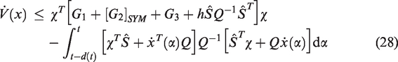
Because Q > 0, the second part of
In fact, an actuator operates on different conditions in an active pantograph. Thus, its actual time delay is difficult to be predetermined. A more probable outcome is that the range of the time delay is ascertained, which is denoted as
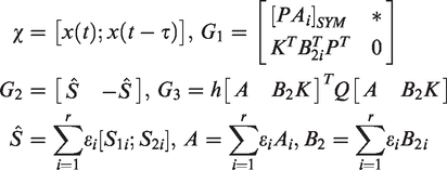
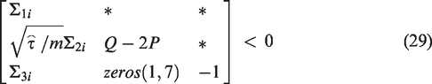
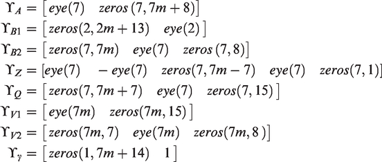
Controller III
Given the positive scalars γ, ρ, and


In Controllers I, II, and III, to obtain a lower bound of the H∞ performance in equation (10), the scalar γ can be regarded as an optimization variable. That is to say, the optimal control gain matrix K can be obtained when
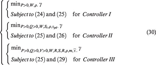
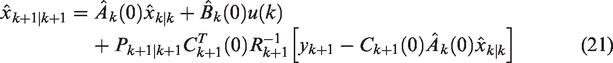
Then, combining the estimator results, the optimal active control force can be described as
Performance investigation
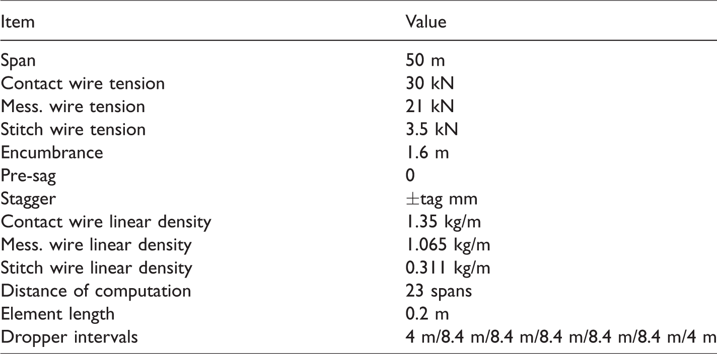
To investigate the effectiveness and robustness of the proposed control strategies, five cases are carried out based on different conditions. In these cases, the real physical parameters of SSS400+ pantograph and Wuhan-Guangzhou railway catenary in China are employed, as listed in Tables 1 and 2, respectively. The pantograph interval is set as 150 m (three spans). Considering the boundary effect, the contact force in the middle eight spans is selected for further analyses.
Physical parameters of SSS400+ pantograph.
Main parameters of catenary of Wuhan-Guangzhou high-speed railway line.
Performance of the estimator for DPCS
Because the pantograph states are critical in the control process, this case independently investigates the performance of the estimator with implementing a nominal DPCS model. The main initial values of the estimator are set as
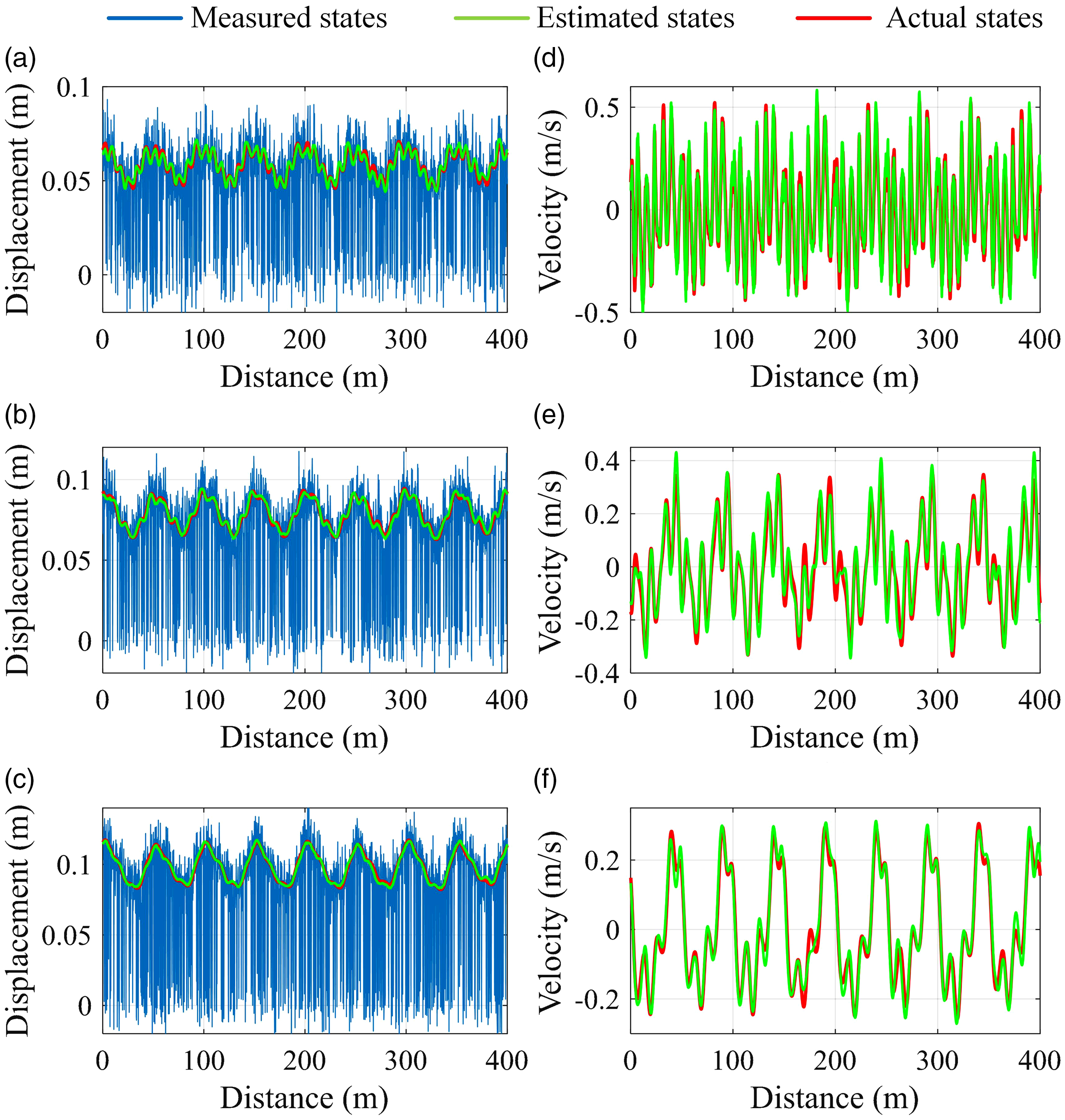
Measured states, estimated states and actual states of the LP at 380 km/h. (a) to (c) Displacements of mass 1–mass 3. (d) to (f) Velocities of mass 1–mass 3.
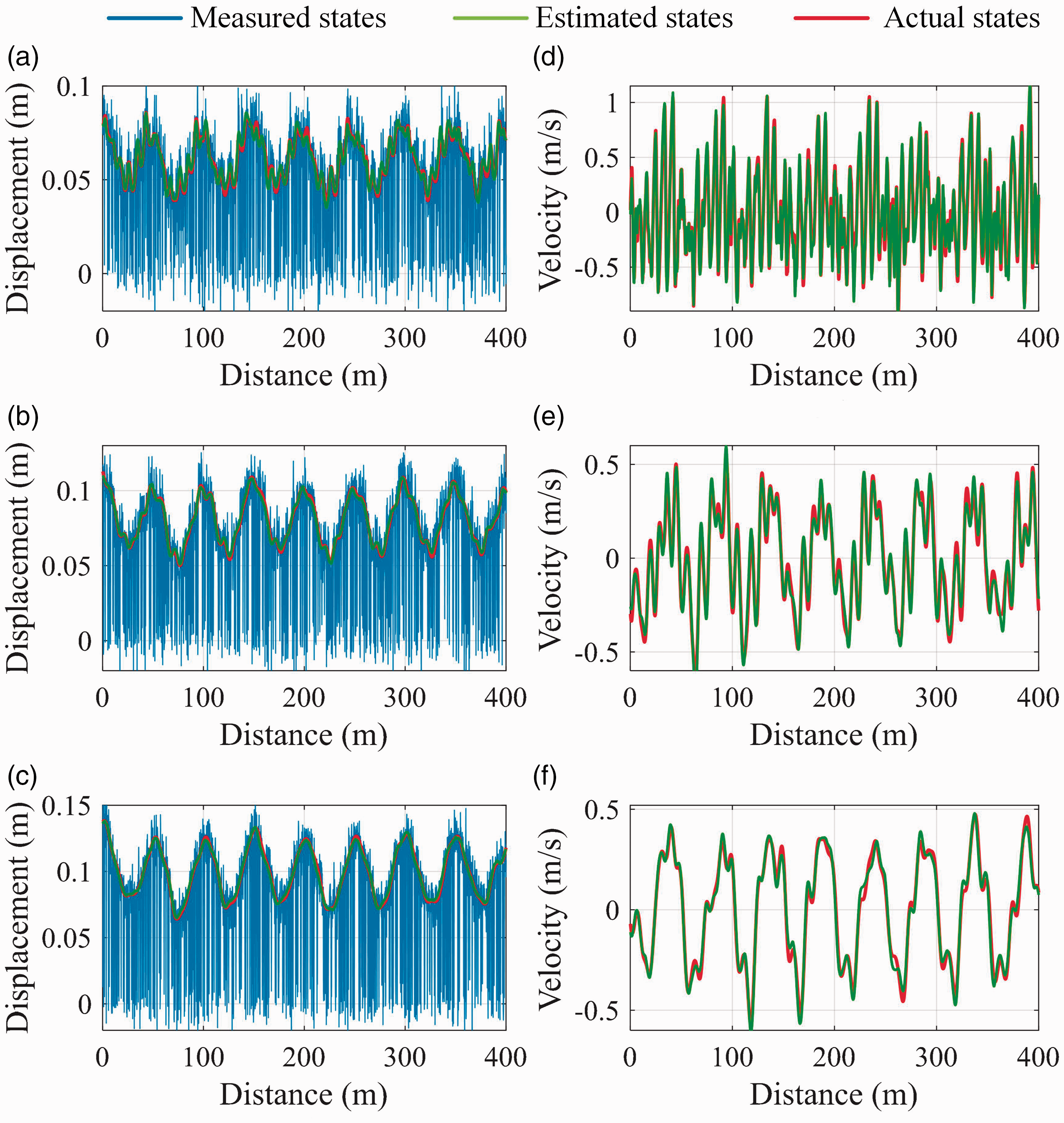
Measured states, estimated states and actual states of the TP at 380 km/h. (a) to (c) Displacements of mass 1–mass 3. (d) to (f) Velocities of mass 1–mass 3.
Performance investigation of controller II for nominal DPCS model and predetermined time delay
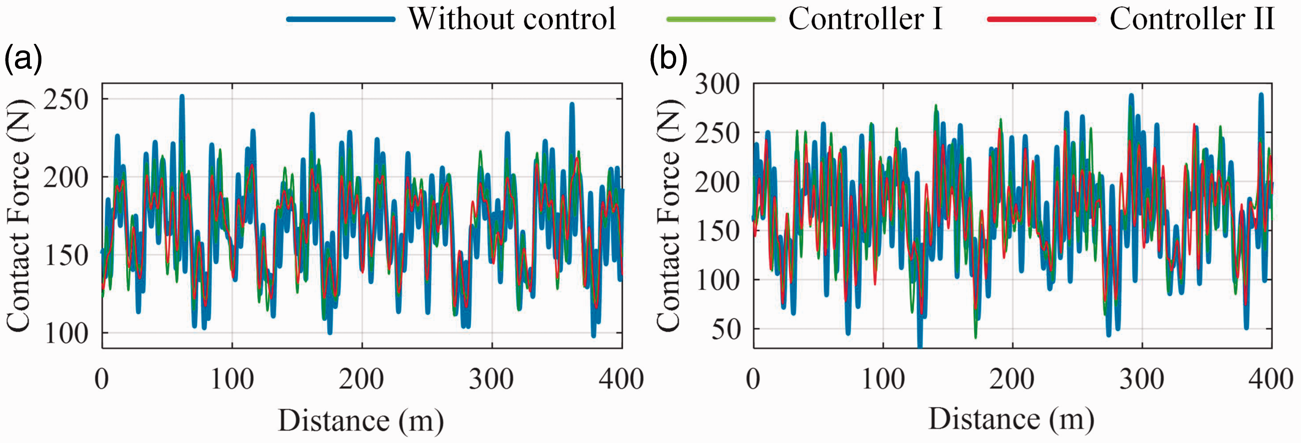
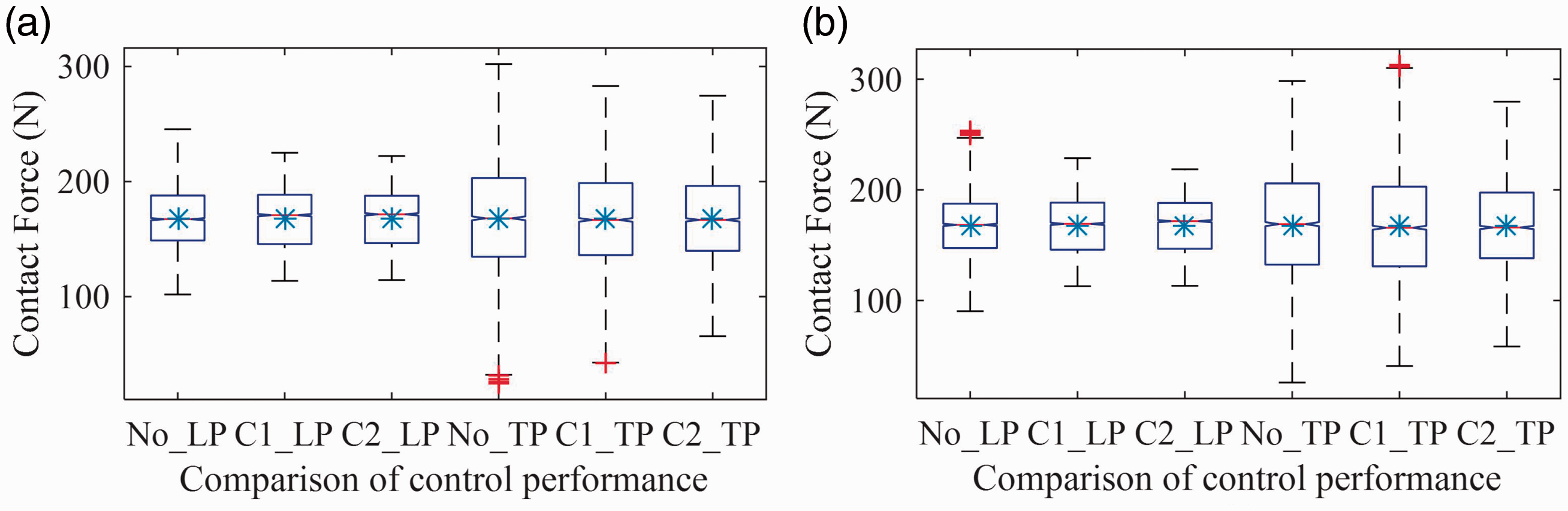
This case investigates the performance of the proposed control strategy II (combine the estimator with the Controller II) with implementing nominal DPCS model that subjects to predetermined actuator time delay. As a contrast, the control strategy I (combine the estimator with the Controller I) is also employed in this and the following cases. The contact force on the LP and TP at 360 km/h with actuator time delay 30 ms is shown in Figure 7. To further analyze the performance, the boxplots of contact force at 360 km/h and 340 km/h are shown in Figure 8(a) and (b), respectively. On each box, the central red line is the median value of contact force, together with the mean value marked by an asterisk, which can be used to evaluate the impact of the control strategy on the central tendency of contact force. The edges of boxes are the 25th and 75th percentiles, which are denoted as q1 and q3, respectively. The fringe red lines denote the extreme outliers of contact force that are greater than q3 + 1.5 × (q3 – q1) or smaller than q1 – 1.5 × (q3 – q1). Correspondingly, the black lines denote the mild outliers, which are within the range of [q1 – 1.5 × (q3 – q1), q1] or [q3, q3 + 1.5 × (q3 – q1)]. Both the boxes and black lines can be used to specify the fluctuation extent of the contact force. From Figures 7 and 8, it can be seen that the contact force fluctuation is decreased by the control strategy II even though the actuator time delay exists, and its performance is superior to control strategy I. In fact, the standard deviation (SD) of contact force on the LP and TP at 360 km/h is reduced by 6.5% and 10.2% by the latter, but it is reduced by 15.5% and 19.2% by former. In addition, the control force is limited within 100 N, which is our second target, as shown in Figure 9. Therefore, the proposed controller strategy II is effective to decrease the contact force fluctuation with predetermined time delay.
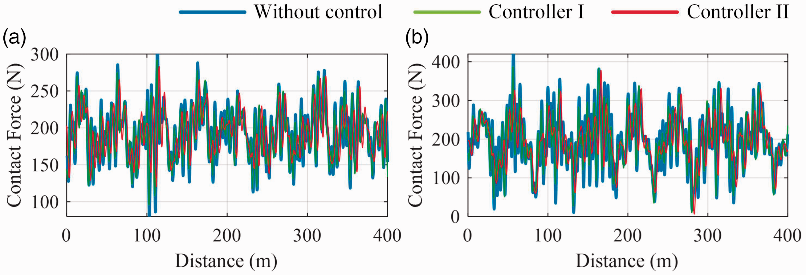
Contact force on the (a) LP and (b) TP at 360 m/h with predetermined actuator time delay 30 ms.
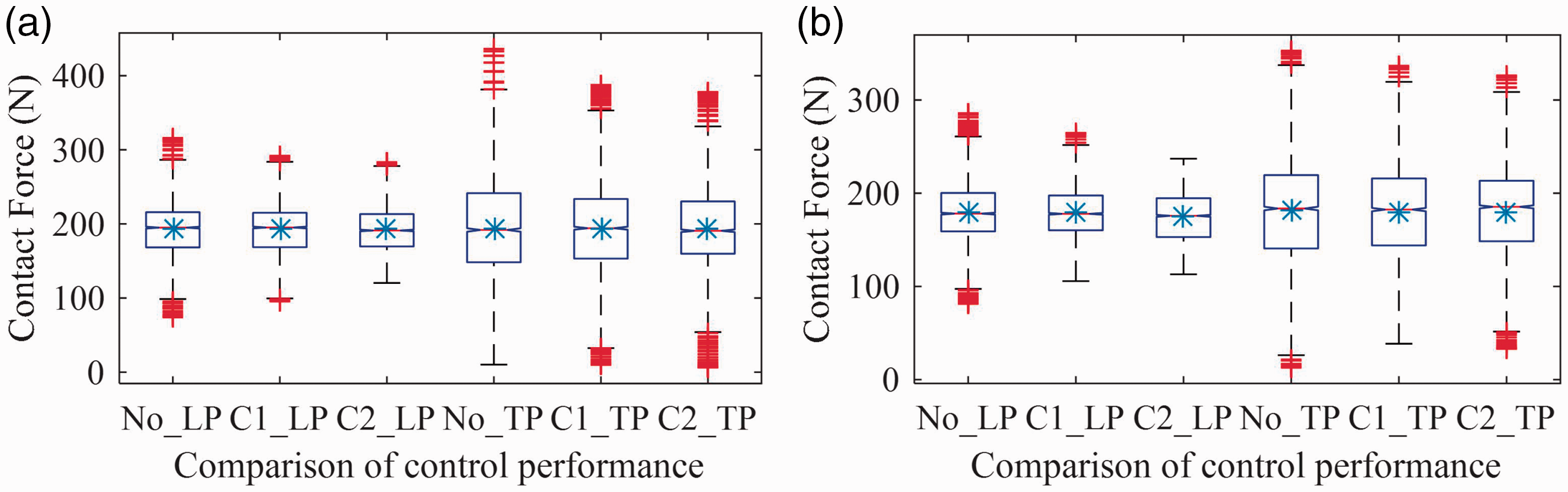
Boxplots of contact force under predetermined actuator time delay 30 ms at (a) 360 km/h and (b) 340 km/h. No_LP, C1_LP and C2_LP denote the LP is without control, with control strategy I and II, respectively. No_TP, C1_TP and C2_TP denote the TP is without control, with control strategy I and II, respectively. LP: leading pantograph; TP: trailing pantograph.
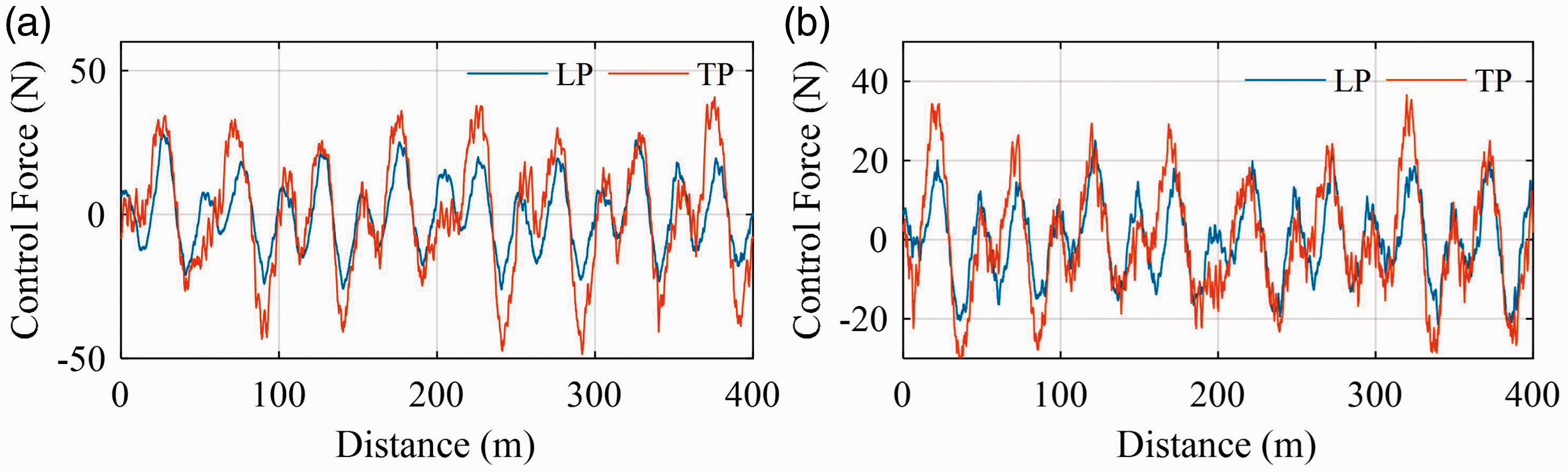
Control force by control strategy II at (a) 360 km/h and (b) 340 km/h.
Performance investigation of controller III for nominal DPCS model and random time delay
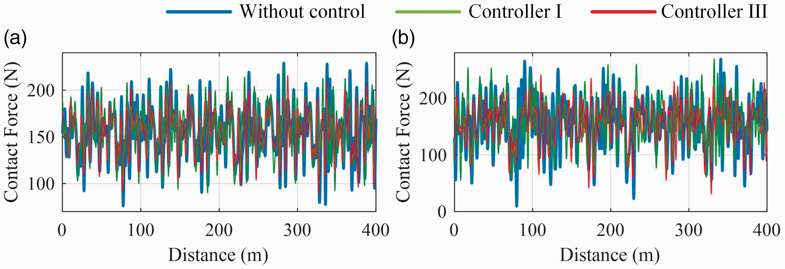
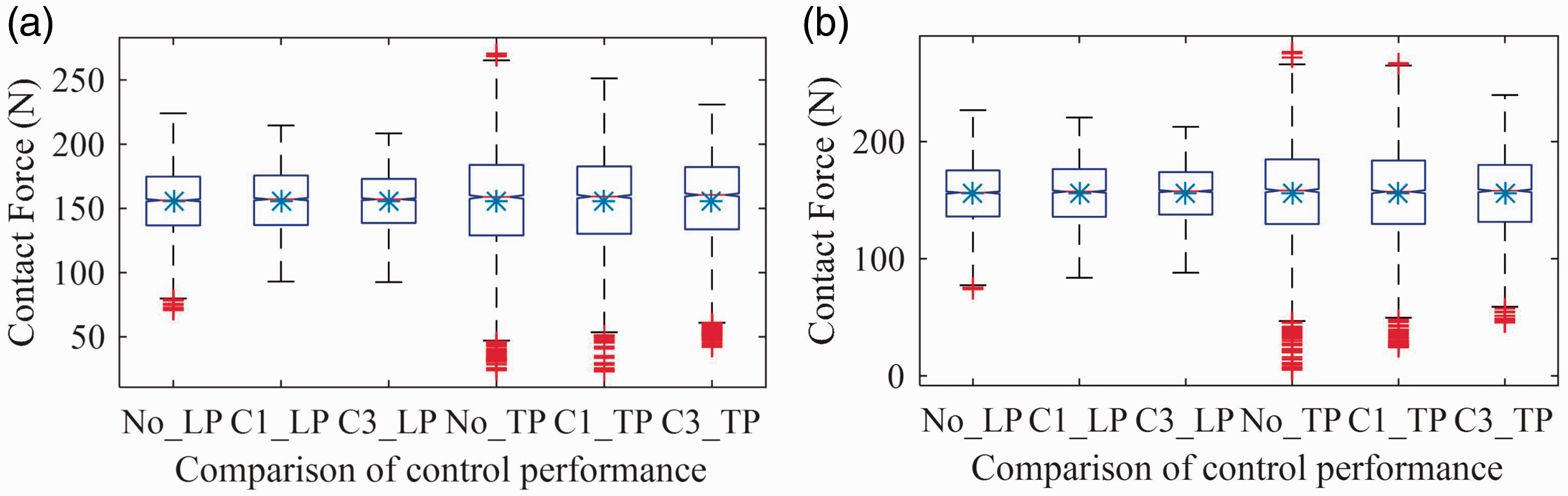
This case investigates the effectiveness of control strategy III (combine the estimator with the Controller III) when the actuator time delay is time varying in each iteration step. Figure 10 shows the contact force on the LP and TP at 340 km/h with random time delay 0∼30 ms. The corresponding SD is reduced by 17.5% and 19.9% by the control strategy III, but it is only reduced by 10.2% and 3.1% by control strategy III. The boxplots of contact force are shown in Figure 11. From Figures 10 and 11, it can be seen that the contact force fluctuation is decreased. In particular, the extreme outliers are obviously reduced. Meanwhile, the control force is limited within 100 N, as shown in Figure 12. Therefore, with a nominal model, the proposed control strategy III is effective to realize the target.
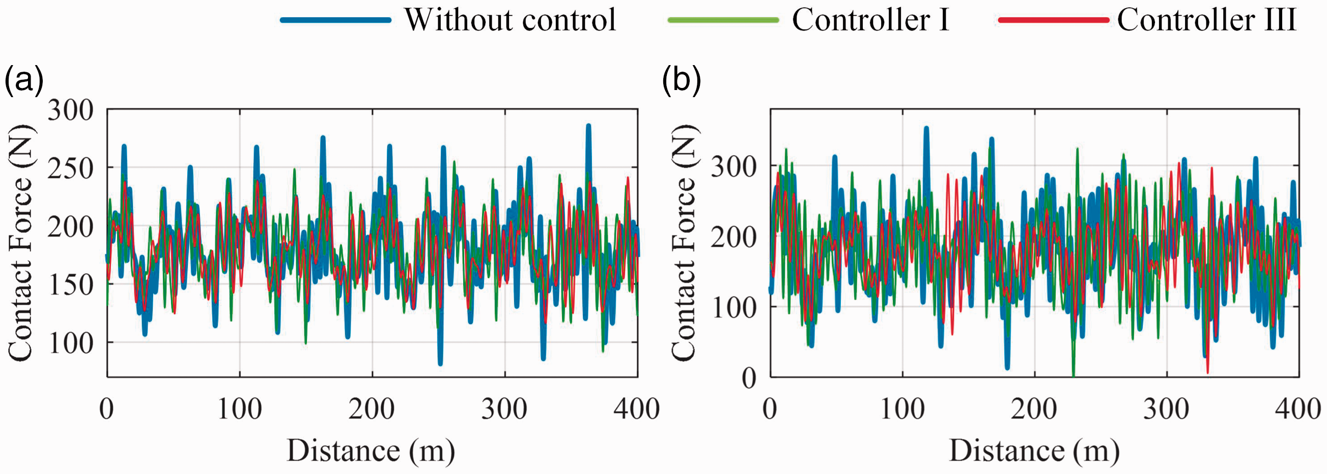
Contact force on the (a) LP and (b) TP at 340 m/h with random actuator time delay 0∼30 ms.
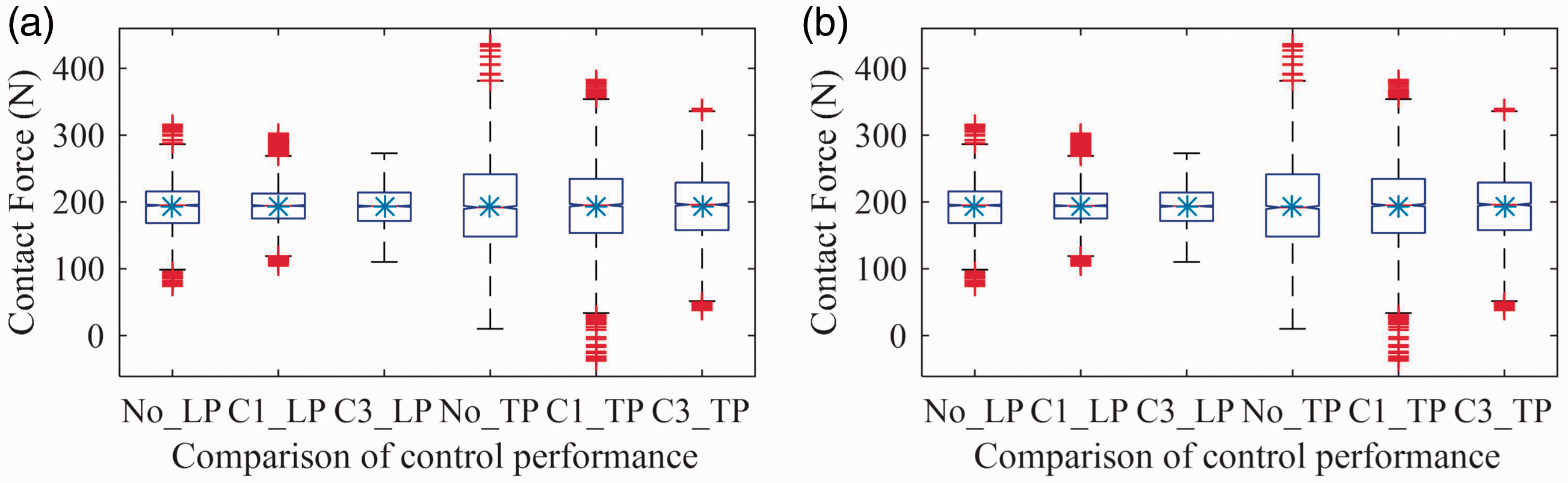
Boxplots of contact force under random actuator time delay 0∼30 ms at (a) 360 km/h and (b) 340 km/h. No_LP, C1_LP and C3_LP denote the LP is without control, with control strategy I and III, respectively. No_TP, C1_TP and C3_TP denote the TP is without control, with control strategy I and III, respectively. LP: leading pantograph; TP: trailing pantograph.
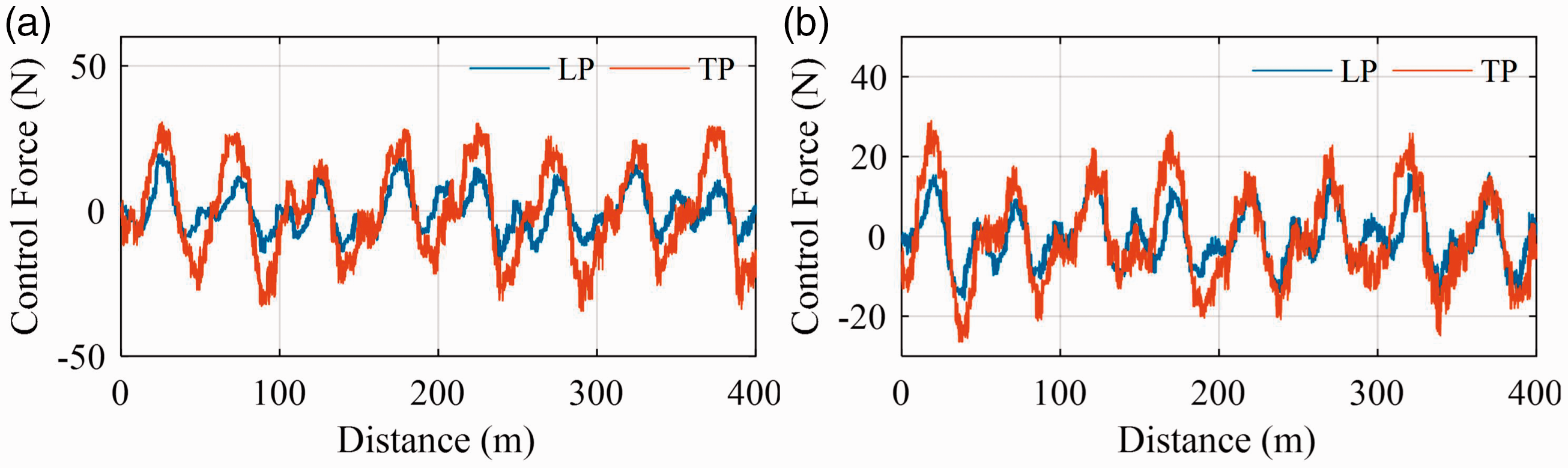
Control force by control strategy III at (a) 360 km/h and (b) 340 km/h. LP: leading pantograph; TP: trailing pantograph.
Robustness investigation of controller II for parametric uncertainties and predetermined time delay
The robustness of the control strategies is investigated on the condition of parametric uncertainties of the pantographs. Because the parameters related to the collector (m1, c1 and k1) have a greater impact on the dynamic behaviors of the PCS than the others, we assume that these three parameters contain uncertainties in this and next case, which are expressed as
Contact force in the example I on the (a) LP and (b) TP at 320 m/h with parametric uncertainties and predetermined actuator time delay 40 ms.
Boxplots of contact force under parametric uncertainties and predetermined actuator time delay 40 ms at 320 km/h. (a) Example II and (b) example III. The meanings of X-axis labels are same with them in Figure 8. LP: leading pantograph; TP: trailing pantograph.
Robustness investigation of controller III for parametric uncertainties and random time delay
In this case, three examples are carried out for investigating the control strategy III by considering random actuator time delay and parametric uncertainties. In example I, m1, c1, and k1 are randomly changed in each iteration step, which are similar with ones in the first example in case 4. In example II, m1 = 5.80 kg, c1 = 9.81 Ns/m, and k1 = 10368.02 N/m. In example III, m1 = 6.25 kg, c1 = 10.27 Ns/m, and k1 = 9898.33 N/m The time delay is set as 0∼40 ms in each step. Simulation results are shown in Figures 15 and 16. In the first example, the SD of the contact force on the LP and TP at 300 km/h is reduced by 14.8% and 18.8% by control strategy III, but it is only reduced by 6.9% and 7.1% by control strategy I. Meanwhile, in examples II and III, it can also be concluded that the contact force fluctuation is decreased from the results shown in Figure 16.
Contact force in the example I on the (a) LP and (b) TP at 300 m/h with parameter uncertainties and random actuator time delay 0∼40 ms.
Boxplots of contact force under parametric uncertainties and random actuator time delay 0∼40 ms at 300 km/h. (a) Example II and (b) example III. The meanings of X-axis labels are same with them in Figure 11. LP: leading pantograph; TP: trailing pantograph.
Conclusion
Aiming to decrease the contact force fluctuation through actively control the pantographs in DPCS considering actuator time delay, two controllers are proposed based on whether the time delay can be predetermined or not. To accurately obtain the pantograph states on the condition of randomly missing measurements, a robust recursive state estimation method is introduced firstly. The effectiveness and robustness of these two estimator-based control strategies are investigated in detail with implementing a nonlinear DPCS model. The results of the employed five cases show that the proposed control strategies are effective to realize the target in different conditions.
Compared with the former controllers designed for active pantograph, the proposed control strategies have two obvious advantages. (1) The actuator time delay is explicitly considered. Therefore, no matter which actuator is chosen, the control strategies are definitely useful to overcome the time delay. (2) The parametric uncertainties of the pantographs are addressed in state estimation and controller design procedure, which ensures the robustness of the proposed controller in the realistic work environment of DPCS.
Footnotes
Declaration of conflicting interests
The author(s) declared no potential conflicts of interest with respect to the research, authorship, and/or publication of this article.
Funding
The author(s) disclosed receipt of the following financial support for the research, authorship, and/or publication of this article: This work was supported in part by the National Natural Science Foundation of China under Grant U1734202 and 5197718.