
Abstract
Combined with the finite element method and the lumped mass method, the integral node dynamic model of a single-rotor multi-input helicopter main gearbox is established. The influence of shaft parameters on dynamic characteristics is analyzed, and each torsional shaft is regarded as a finite element node to derive the system dynamic equation. In addition, the dynamic model of the meshing pair element is established by lumped mass method, and these elements not only include internal excitations such as time-varying meshing stiffness and transmission error, but also carry the external load. The differential equations of the system are solved by the Fourier series method. The dynamic responses of the converging element and the planetary gear train are obtained. The load-sharing coefficients of these elements are calculated by the influence of the shaft structural parameters. A parameter optimization method is proposed to improve the system load characteristics, which provides a theoretical support for the design of helicopter main transmission system.
Keywords
Introduction
The single-rotor multi-input helicopter main gearbox has three identical input branches, converging on a central gear, then the power follows one way to the planetary gear system and the rotor, while the other way to the tail chain. The transmission chain is quite long and it includes many branches, which makes the structure very complicated. In addition, the system is under large load power and severe working conditions. The converging element and the planetary gear train bear dynamic meshing forces in multiple directions, if the load cannot be evenly distributed between the branches, and the carrying capacity will be reduced, resulting in component overload and vibration. Its load-sharing characteristics analysis is for the sake of prolongling system life, reducing vibration and improving system stability, which is regarded as the research hotspot.1–3 Therefore, the load-sharing analysis is of great significance.
During the past several decades, some significant studies about solving the gearbox dynamic problems have been proposed. About multi-stage gear analysis, Chong et al. 4 proposed a generalized multi-stage gear drives design methodology by integrating the dimensional design and the configuration design processes in a formalized algorithm. Choy et al. 5 presented a three-stage multi-mesh gear transmission systems, and predicted the overall system dynamics by the influence of transmissibility, input speed, rotor imbalances and support. Dzitkowski and Dymarek 6 applied the reduction method based on an active synthesis to obtain a desired mechanical effect by properly selecting the dynamical system properties. Tanaka et al. 7 predicted gear noise from the vibration step to the sound-generation step in a multi-stage gear system, and analyzed the distribution of the sound-pressure around the gearbox and identified the intense noise areas. Thompson et al. 8 applied a basic multi-objective optimization procedure to the design of a three-stage spur gear reduction system, which was subject to identical loading conditions and design criteria.
Regarding load-sharing analysis, Kahraman 9 defined load-sharing in a planetary gear sets by establishing the mathematical model and validated in experimental work under quasi-static conditions. Bodas and Kahraman 10 studied the effect of manufacturing and assembly error on load-sharing behavior in a planetary gear set. Sheng et al.11,12 presented a new non-linear bending-torsional coupled model for double-row planetary gear set, and studied the influence of planet’s eccentricity error and ring gear’s supporting stiffness on planetary gear train. Sekar studied load-sharing ratio based on maximum fillet stresses through the asymmetric three-teeth helical model by finite element method, and investigated the influence of gear ratio, transverse contact ratio, top land thickness coefficient and the pinion teeth number. 13 Nevertheless, the influence of shaft parameters on load-sharing behavior has not been adequately analyzed in these researches.
In terms of FEM-LMM mixed gearbox modeling method, Choi et al.14,15 applied a finite element method with distributed mass for lateral and torsional vibrations, and it was coupled to a lumped mass model describing the axial vibrations, which is the mixed modeling methodology inspiration for this paper.
Stringer presented a comprehensive FEM transmission model by subcomponent, and the multi-node dynamic model of the gearbox was combined with multiple shafts connected by multiple gears of different configurations. 16 However, parameter optimization based on multi-node dynamic modeling has not been captured by these researches.
About auxiliary parameter for nonlinear oscillators, several solving methods such as asymptotic method, homotopy perturbation method, and variational iteration method have been presented by scholars.17–19 While parameter analysis method for multi-stage gearbox has not been widely applied.
In summary, scholars have focused on the planetary gear train or the single meshing pair; however, the research on the whole helicopter main gearbox has not been widely studied. More importantly, most scholars normally make the derivation of equations in the meshing gear pair, and research on shafts nodes modeling is rarely seen in gearbox dynamic analysis, so it is of great importance for the gearbox design.
Dynamic modeling of multi-node system
The dynamic model of a typical single-rotor multi-input helicopter main gearbox is shown in Figure 1. Figure 1(a) is the system model and Figure 1(b) shows the multi-node model, which is based on the new method.
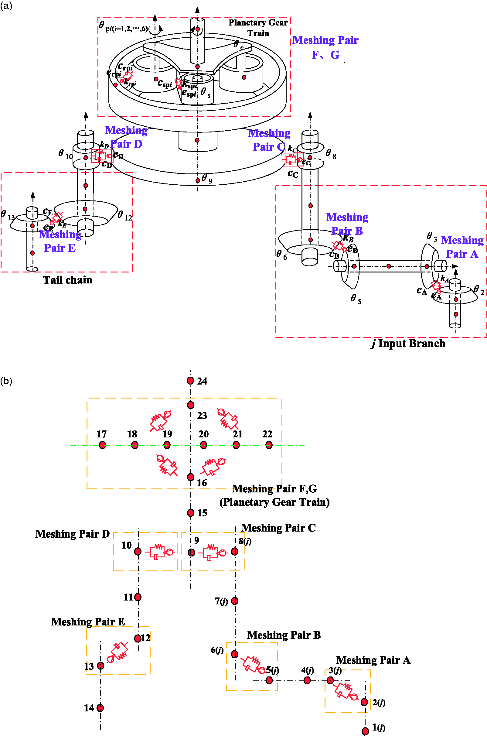
Dynamic model of the multi-node system. (a) Dynamic modeling. (b) Node modeling.
The main gearbox has a total of three input branches and two output branches (tail chain output branch and rotor output branch).
20
According to Figure 1, there are seven meshing elements (A, B, C, D, E and F) in the system, and the elements F and G are internal and external meshing pairs in planetary system, which contains one sun gear (node 16), six planet gears (nodes 17 to 22) and one carrier (node 23). θ is the rotational degree of freedom (DOF) of each node, and each DOF corresponds to one node. The system's generalized coordinate vector X is

Dynamic modeling of the meshing pairs
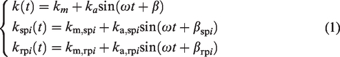
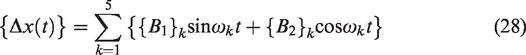
For the seven meshing pairs labeled A, B, C, D, E, F, and G in Figure 1, the time-varying meshing stiffness can be expressed in the Fourier series with meshing frequency ω
21
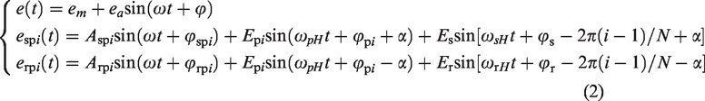
Similarly, transmission errors are shown in the same way
The relative displacement along the meshing line X(t) is defined as follows

The dynamic forces of each gear pair F(t) are defined as follows

Differential equation of multi-node system
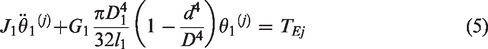
According to the above dynamic modeling, the differential equation of the multi-node gearbox model can be deduced through the Newton’s law, as is shown below:
Node 1
Node 2

Node 3

Node 4
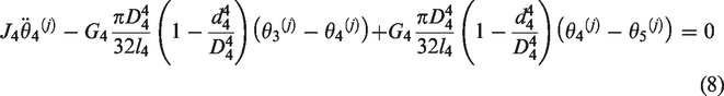
Node 5

Node 6

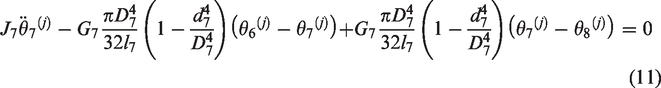
Node 7
Node 8

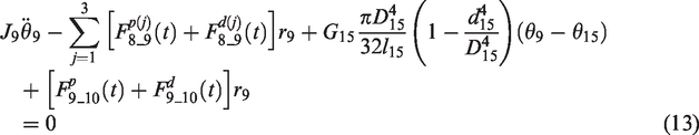
Node 9
Node 10

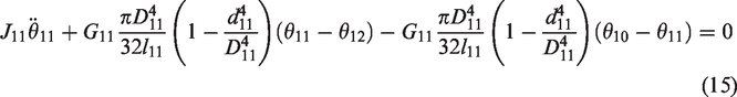
Node 11
Node 12

Node 13

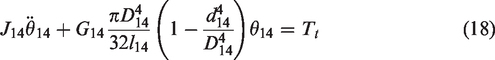
Node 14
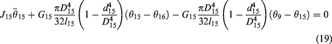
Node 15
Node 16

Nodes 17–22 (pi)

Node 23

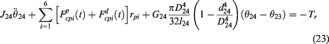
Node 24
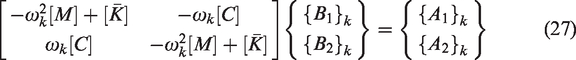
The equations for each DOF could be written as the following matrix – vector form

The excitation {F} could be expanded to Fourier series with the fundamental frequency, kth order excitation is

The excitation would contribute to a certain response

The dynamic response is linear superposition of the result corresponded by each order
Numerical calculation and dynamic analysis
Parameter setting and response calculation
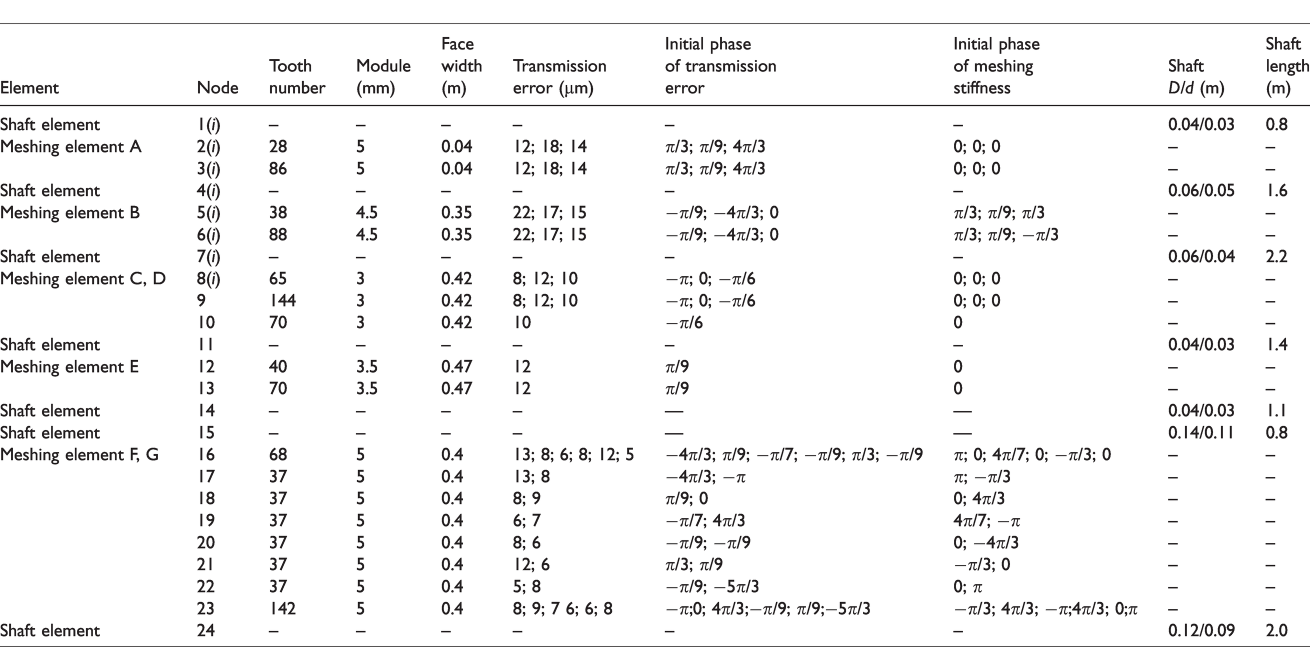
The node parameters of the system are shown in Table 1. Besides, the system is powered by three engines, the maximum output power of each engine is 1500 kW, output speed is 10,000 r/min. The output power of rotor is 1000 kW, the rotor speed is 300 r/min. The transmission mechanical efficiency is 95%.
Single-rotor multi-input helicopter main gearbox node parameters.
In this paper, the Fourier series method is applied to solve the derived differential equations through computational programming, and the time-domain dynamic response of load-sharing-related DOF is obtained and shown in Figure 2. It indicates that the dynamic response exhibits a periodic variation under multi-frequency excitation caused by time-varying meshing stiffness and various errors. The three input branches are important components in single-rotor multi-input helicopter main gearbox, they are in the same structure but different excitation, and as a result, they show distinct response amplitude.
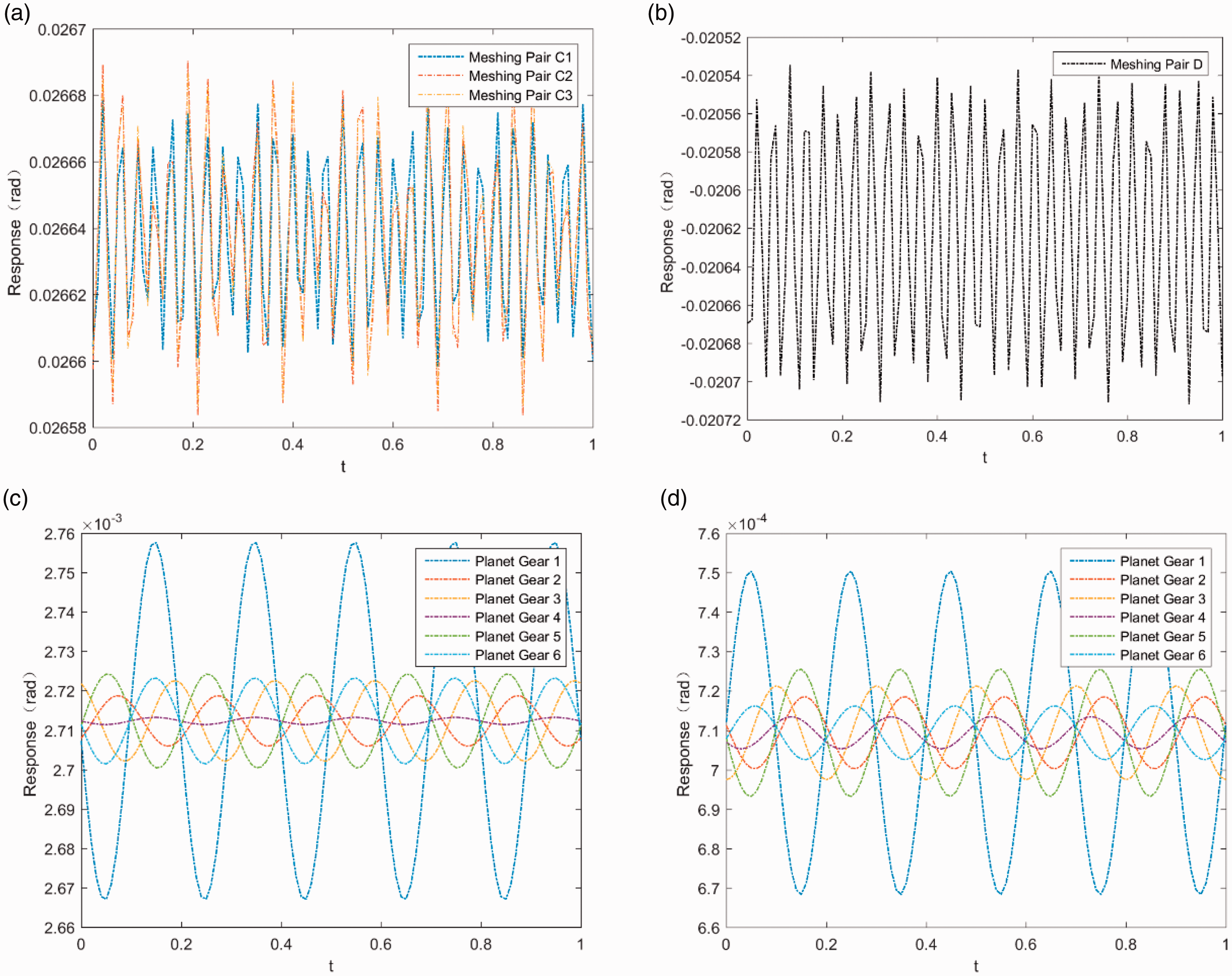
Time-domain dynamic response in confluent stage. (a) Meshing pair C. (b) Meshing pair D. (c) Meshing pair F. (d) Meshing pair G.
By comparison, it can be seen that the dynamic response of meshing element E has the maximum amplitude due to the load of tail chain. In addition, under the converging influence of the three-input branches, the magnitude of the response of the converging element (composed of the meshing pair C and D) is also relatively large, and thus needs further analysis. Regarding the responses in the internal and external meshing pair (element F and G), planetary gear 1 is greater than other planetary gears due to its largest transmission and manufacturing error.
Load-sharing coefficient calculation
Due to the manufacturing error, installation error, gear wear and other factors in the planetary gear train, the load distribution on each gear pair is inconsistent. The converging element also has inconsistent load distribution due to the multiple convergences of input branches. The basic assumption is that some factors like transmission error and phase difference are intrinsically existing. A method is proposed by changing the thickness and length of the shaft, and the load-sharing characteristics can be improved, thus providing technical support for the shaft parameter design.
The load-sharing coefficient b is defined as the ratio of the maximum dynamic meshing force to the mean value in separate branch
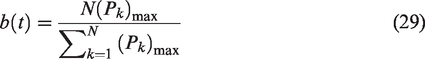
According to dynamic response and time-varying meshing stiffness, the meshing force could be calculated, and then the load-sharing coefficients of the converging element and planetary gear systems could be computed, which are depicted in Figure 3. The load-sharing coefficients also show the periodic variation under multi-frequency excitation. The value of converging element is larger than that of the planetary gear system due to the complex coupling impact of three input branches and tail chain. In terms of planetary gear systems, the external meshing coefficient is larger than that of internal pair.
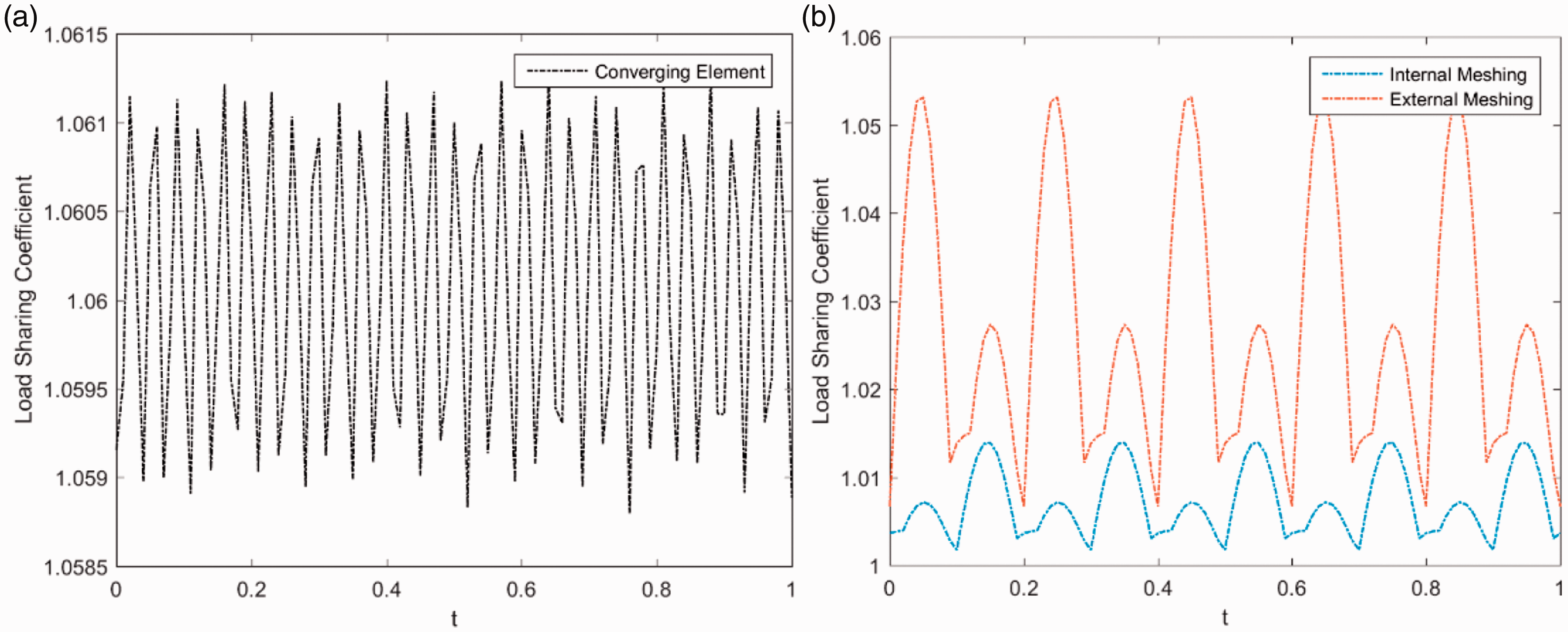
Time domain of load-sharing coefficient in the system. (a) Converging element. (b) Planetary gear train.
Analysis on load-sharing coefficient influenced by shaft wall thickness
The wall thickness is characterized by the ratio of the external diameter to the internal diameter of the hollow shaft, which is symbolized as α. In this case study, 0.6 ≤ α ≤ 0.9 is originally set, and the influence of the thickness on load-sharing coefficient at this interval is investigated. By changing the value of α in each shaft, the maximum load-sharing coefficient is calculated without changing other parameters, and the result is shown in Figure 4.
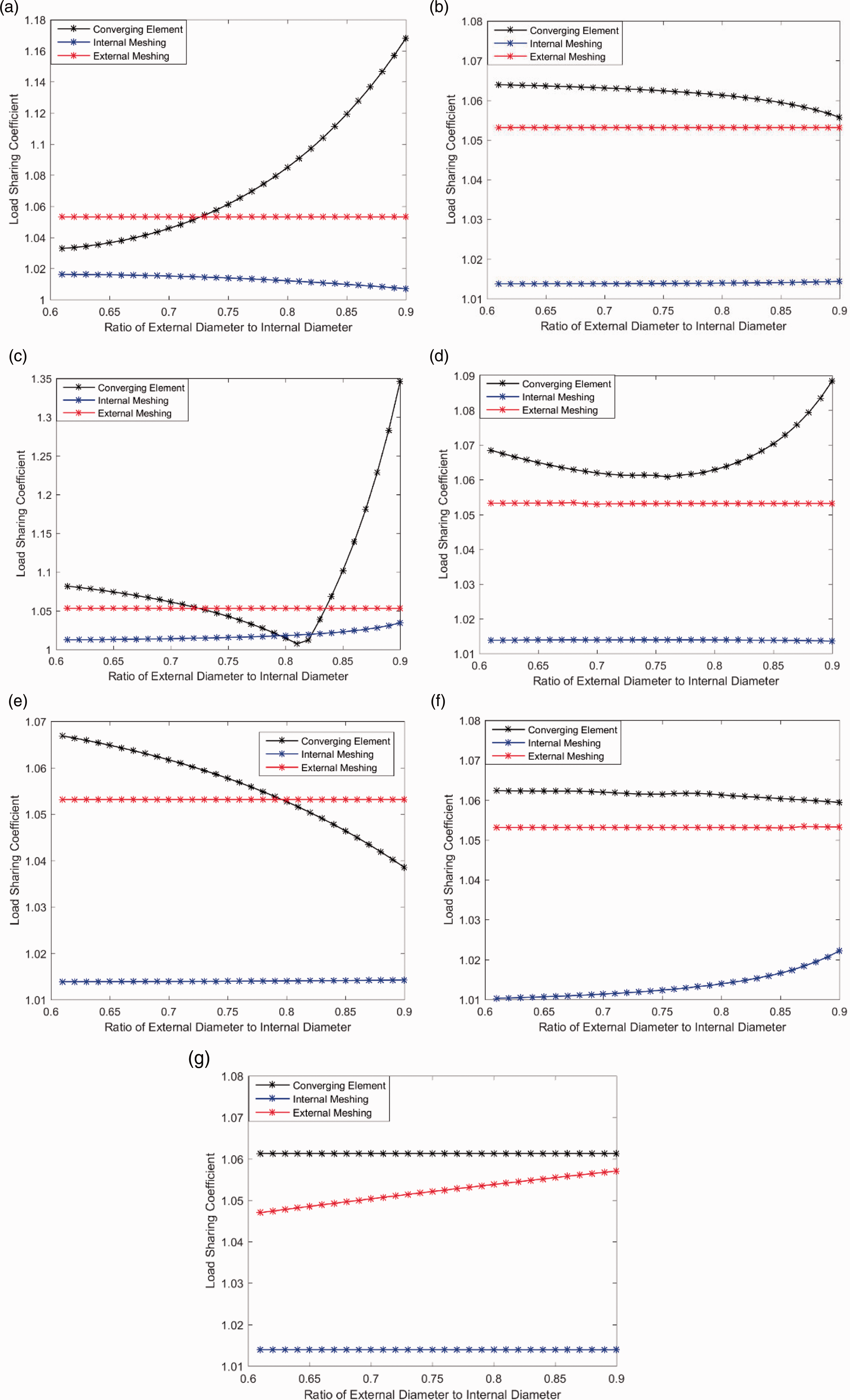
Load-sharing coefficient influenced by wall thickness. (a) Node 1. (b) Node 4. (c) Node 7. (d) Node 11. (e) Node 14. (f) Node 15. (g) Node 24.
Figure 4(a) shows that the load-sharing coefficient of converging element is the lowest (1.032) when α1 is 0.57. If α1 is greater than 0.7, the load-sharing coefficient of internal meshing in the planetary gear is reduced, but the change is not significant. The load-sharing coefficient of external meshing does not change with α1.
Figure 4(b) demonstrates that when α4 is greater than 0.8, the load-sharing coefficient of the converging element decreases more significantly, while the other two stages do not change apparently. Therefore, the thin-walled characteristics of Node 4 can improve the system stability.
Similarly, from Figure 4(c) to (e), it can be seen that when α7 is equal to 0.81, α11 is equal to 0.76, and α14 is equal to 0.9, the load-sharing coefficient of the converging element can also be reduced. Among them, the influence of the shaft diameter ratio of Node 7 is the most obvious, and therefore it is the key shaft of the load-sharing characteristics of this element.
According to Figure 4(f) and (g), the wall thickness of Node 15 and Node 24 are key factors in internal and external meshing pairs, and when the diameter ratios are equal to 0.6, the system load-sharing characteristics tend to be better.
Analysis on load-sharing coefficient influenced by shaft length
The load-sharing coefficient is calculated by changing the shaft length of each node within the allowable range, without changing other parameters, and the result is shown in Figure 5.
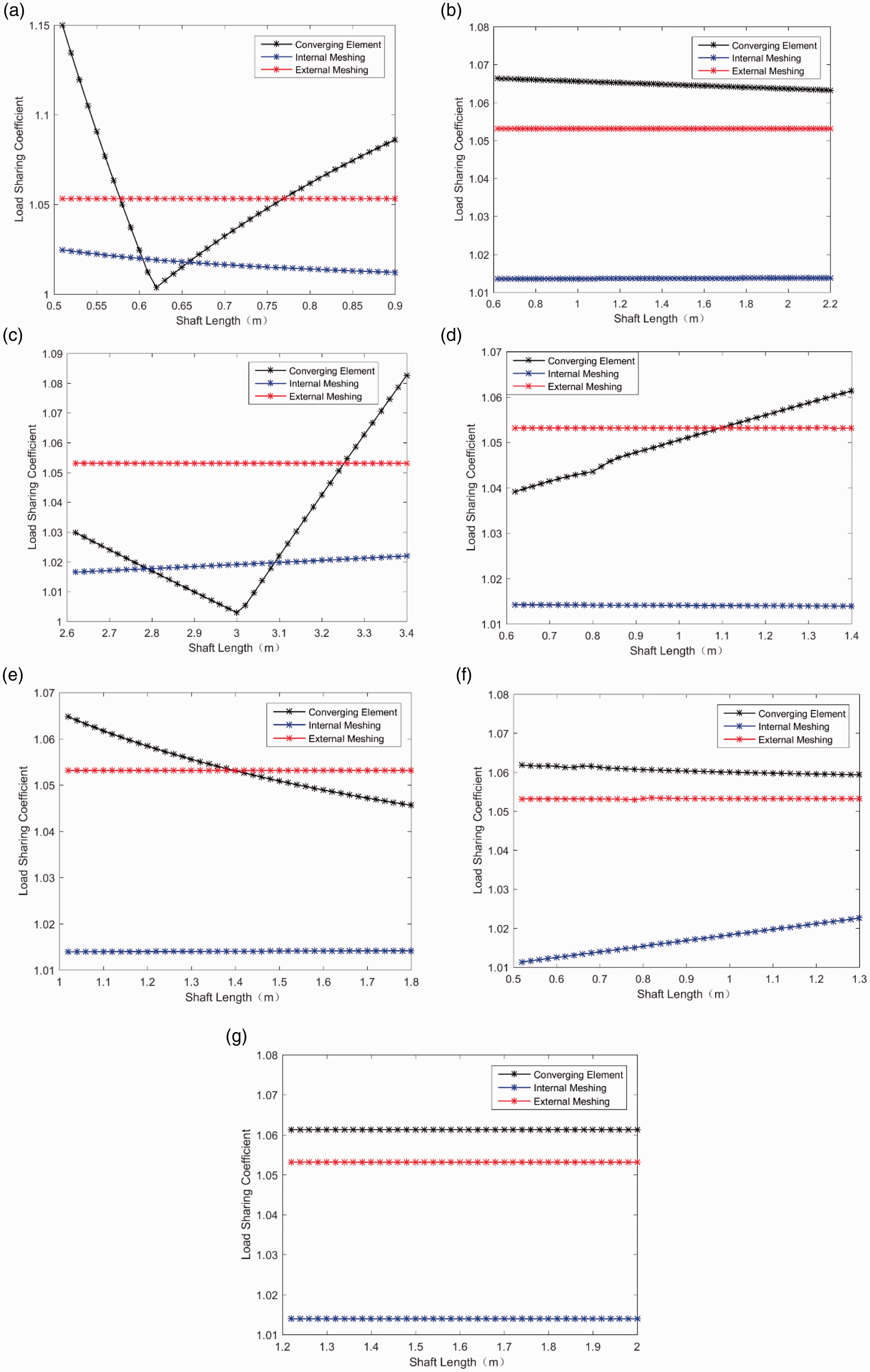
Load-sharing coefficient influenced by shaft length. (a) Node 1. (b) Node 4. (c) Node 7. (d) Node 11. (e) Node 14. (f) Node 15. (g) Node 24.
In Figure 5(a), it can be concluded that l1 is the most effective parameter in improving the load-sharing characteristics of the converging element. When l1 is equal to 0.62 m, it is the turning point of the figure, which can reduce the load-sharing coefficient to 1.01. Similarly, it could be noted from Figure 5(b) to (e) that when l4 is 2.2 m, l7 is 3.0 m, l11 is 0.6 m, and l14 is 1.8 m, the load-sharing coefficient could be reduced as well, while the other two elements are not affected. From Figure 5(f), the Node 15 is still the key shaft of the load-sharing characteristics in the planetary gear system. When l15 is short, the system internal meshing load-sharing characteristics tend to be better. The change in the length of the Node 24 does not affect the load-sharing coefficients of the three elements.
Structural parameter optimization based on load-sharing coefficient analysis
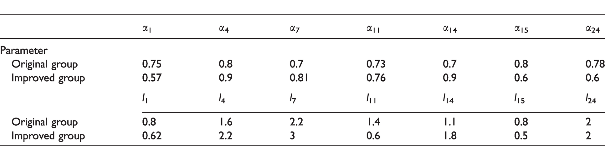
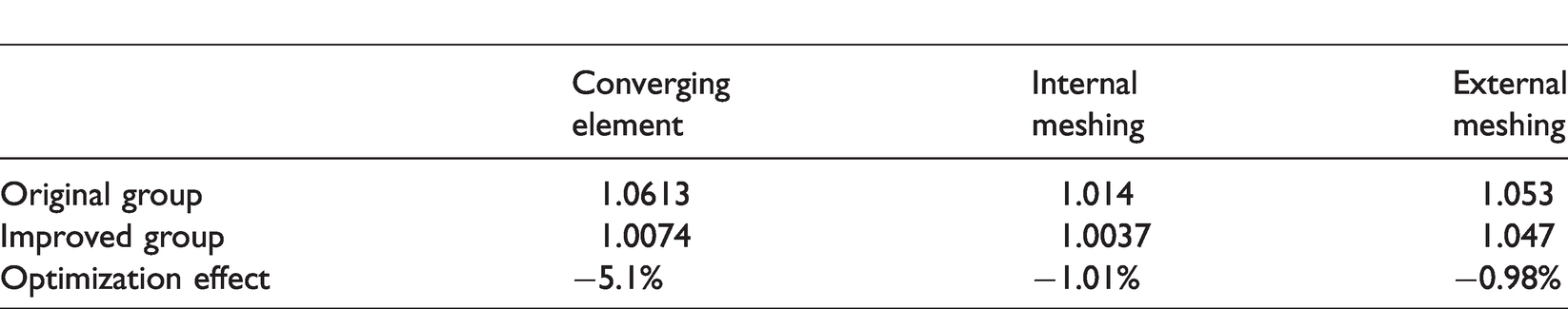
Based on the above analysis, according to the relationship between the shaft parameters and the load-sharing coefficient at each stage, the improved parameters at the shaft node are obtained, and thus the original parameters are replaced with the improved, as is shown in Table 2. The load-sharing coefficients of the converging element and planetary gear train are recalculated, and the improved effect is shown in Figure 6 and Table 3. As indicated from the figure and the table, the waveform and phase of both elements do not make a change, but the load-sharing coefficients have been significantly reduced. Since Node 1, Node 4, Node 7, Node 11 and Node 14 can effectively improve the load-sharing characteristics in converging element, the coefficient of this element is reduced by 5.1%, which is more effective than that of the other two elements. There are not many parameters affecting the load-sharing coefficient of the planetary gear system, but the internal and external meshing pairs are still improved by 1.01% and 0.98%, respectively.
Parameter optimization of the hollow shaft.
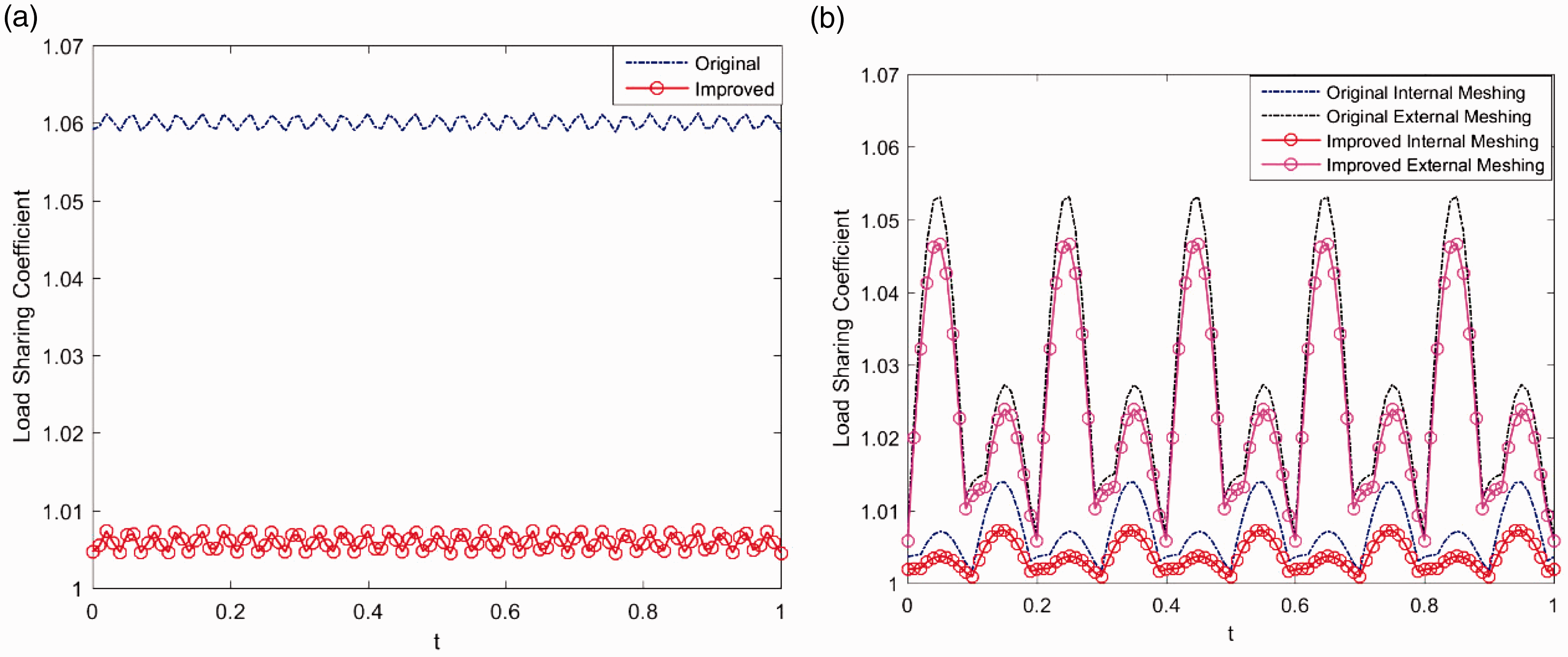
Load-sharing optimization. (a) The converging element. (b) The planetary gear train.
Shaft node parameter optimization.
In summary, a parameter optimization method to improve the system load-sharing characteristics is provided for the gearbox design.
Conclusion
Based on the load-sharing characteristics analysis, this paper proposes a structural parameter optimization method for single-rotor multi-input helicopter main gearbox. By establishing the multi-node dynamic model, deducing coupling differential equations, and analyzing load-sharing coefficients of three stages, the influence law of shaft thickness and shaft length is obtained. The results could draw the following conclusions:
The dynamic response shows a periodic variation under the multi-frequency excitation, and meshing elements C, D, and E have relatively larger response. Node 7, Node 15 and Node 24 are key nodes regarding load-sharing characteristics of the converging element, internal and external meshing elements, respectively. By changing the wall thickness (shaft diameter ratio α), the load-sharing coefficient could be reduced according to the corresponding influence law. The length parameter of Node 1 has the most obvious effect on the improvement of the load-sharing characteristics in the converging element; the length parameter of Node 15 is the key parameter related to the planetary gear element; Length of the Node 24 does not affect the load-sharing coefficients in these elements. By the structural parameter optimization method, the load-sharing coefficient of the original group can be reduced by 5.1%, and the load-sharing characteristics of internal and external meshing pairs can be improved by 1.01% and 0.98%, respectively.
Footnotes
Acknowledgements
The authors gratefully acknowledge the help of Professor Rupeng Zhu and Dr Yuan Chen for the guidance of the final revision.
Declaration of conflicting interests
The author(s) declared no potential conflicts of interest with respect to the research, authorship, and/or publication of this article.
Funding
The author(s) disclosed receipt of the following financial support for the research, authorship, and/or publication of this article: The work described in this paper is fully supported by Jiangsu Key Laboratory of Precision and Micro-manufacturing Technology Foundation (Grant No.ZAA1400105); Aeronautical Science Foundation of China (Grant No.20161852018); Innovation Fund of National Commercial Aircraft Manufacturing Engineering Technology (Grant No.SAMC13-JS-13-021).