
Abstract
An unbalanced propeller can affect a quadcopter’s performance due to vibration, also decreasing its thrust’s yield. Analyses were conducted to determine the correlation between vibration in the dynamic movement of a balanced and an imbalanced propeller using a laser vibrometer (portable digital vibrometer) PDV-100, to determine the correlation between propeller rotational speed and its vibration, as well as to determine the propeller’s maximum rotational speed to avoid over-vibration. The vibration analysis was conducted on a carbon fiber 2-blade propeller by comparing the results of vibration tests with the propeller blade contour. The vibration response of the propeller has been analyzed at three points, respectively the hub, the center, and the tip of the blade, to determine the point having the largest value of the vibration on the propeller running at a maximum rotation speed of 7000 rpm. The same analysis was made on two propellers: the first one of type 1340 with a diameter of 13 inches and the second one of type 1447 with a diameter of 14 inches. The vibration was reduced by propeller’s static balancing, thus increasing the propeller stability. The result showed that an imbalanced propeller generated a decrease in the rotational speed and higher vibration values compared to the balanced propeller. The vibration values showed a linear dependency to the rotor speed; the higher the speed, the bigger the vibration. The limit of rotational speed for the balanced model of the 1340 type propeller was 5000 rpm whilst the corresponding value for the 1447 type propeller was 4500 rpm. Finally, the result was used to optimize the propeller’s overall performance.
Introduction
The main source of thrust or lifting force of a quadcopter system is the rotation of its four sets of rotors/propellers. The variation of the generated thrust is linearly dependent on the angular velocity of the rotor–propeller. Propeller performance can be analyzed based on the impact of the airfoil vortex’s response and material of the blades.1,2 The elasticity of the material affects the blade’s deformation during the rotation; a lighter material with higher elastic modulus is required to ensure that the impact of the airfoil vortex leads downward to obtain an optimal thrust value. Momentum and blade element theory3–5 can be used in propeller’s performance analysis. Depending on the propeller’s structure, the magnitude of the generated thrust depends, among others, on the number of blades, propeller diameter, the angle of attack or pitch angle, and the speed of the propeller.6–10 In two-blade propellers, the blades must have same characteristics especially in terms of weight and angle of attack. Propellers used in quadcopters are generally made of plastic, carbon fiber, or other elastic materials. To ensure the same thrust for each of the blades, propeller’s balancing is needed. Usually, propellers’ balancing is made based on the pendulum thrust balance concept; however, this study utilizes two magnets to attach the propeller’s shaft to the balancer. 11 The aim of the work was to analyze the dynamic movement of the propeller with respect to the vibration which occurs when the propeller rotates at its maximum speed, corresponding to the rotor’s rotational frequency of 118 Hz. A laser vibrometer, Polytech PDV-100, has been used to measure both the propeller’s rotation frequency and the amplitude of the vibration. Through this measurement, the variation of speed and frequency during a complete rotation of the propeller was continuously analyzed over a 640 ms sampling time using a 48 kHz sample frequency for each point. The propeller’s balancing was the key factor in reducing vibration velocity. The analyses were conducted in steps: the effect of using an imbalanced and balanced propeller, and then the correlation between the propeller rotation speed and vibration velocity. The result was used to optimize the propeller performance and rotational speed. A balanced propeller always generates a constant value of frequency. The propeller’s vibration behavior was compared on three areas of the blade, i.e. the hub, the center, and the tip. Two types of carbon fiber propeller were used in the analysis, i.e. 13-inch propeller with 4-inch pitch (Propeller 1340) and 14-inch propeller with 4.7-inch pitch (Propeller 1447). This analysis was necessary to prove that this method can be used for all types of propellers and also to ascertain which area on the blade is subject to the largest vibration. The vibration was also measured on the widest area on the blade with rotational speed varied from 1000 to 5000 rpm to determine the limit of rotational speed and avoid over-vibration. Finally, this method was used to verify the effect of using a balanced propeller to its performance.
Non-contact vibration analysis techniques
Monitoring of the propellers’ condition was performed using contactless vibration measurement technique, by the means of a laser Doppler vibrometer (Polytec PDV-100). The laser vibrometer can also be used to investigate the dynamic properties of various structures based on Eulerian or Lagrangian reference frames.12–14 A laser vibrometer with a frequency range from 0.5 Hz to 22 kHz was used to monitor dynamic propeller movement. The laser beam is focused at a specific point on the propeller’s surface and the blade will sweep through the laser beam during rotation. The propeller is connected to a rotor which can develop a maximum speed of 7000 rpm. With the added weight of the propeller, the rotor propeller’s maximum speed will decrease. The challenge of the research is to process the vibration signal in correlation with the propeller’s contour. Propeller curve contour is influenced by the pitch angle of the propeller model.
Experimental setup
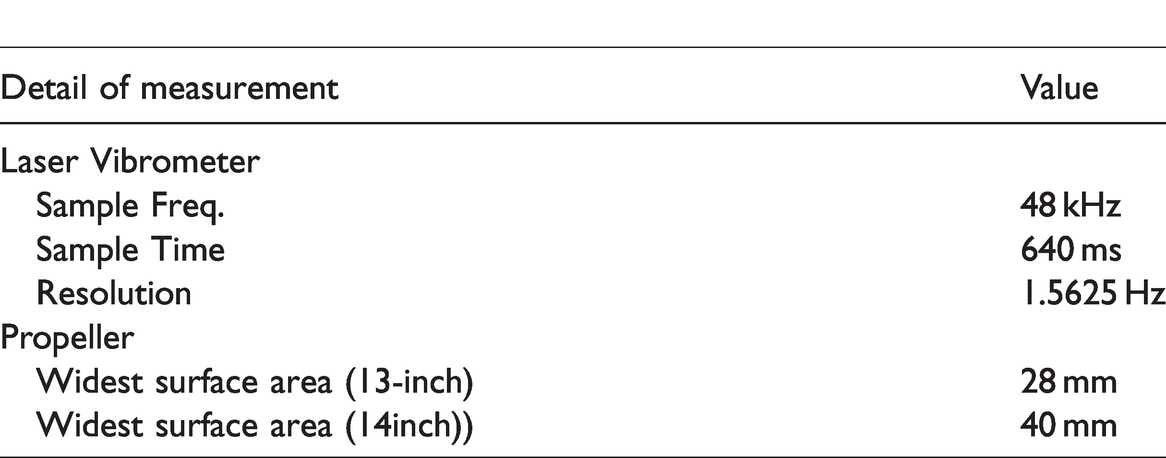
The laser vibrometer was placed perpendicularly to the rotor propeller’s rotation plane. The rotor fixture is made of rigid material to prevent vibration and position shift during measurement. The vibration velocity was compared between a balanced and an unbalanced propeller, at maximum rotation speed. The measurement was performed on three specific areas on the propeller, which are the ‘tip’, identified by symbol A in this paper, the ‘center of the blade’ marked with symbol B, and the ‘hub’ identified by the” C” letter. Each area has been subjected to 128 s of sampling time and data collection began when the propeller had reached the maximum speed in stable condition. In this research, a laser vibrometer with a bandwidth of 0.1 kHz was used to collect data on every 240 Hz sample frequency with a resolution of 7.8125 MHz. The detail of the experimental setup can be seen in Figure 1. Two types of carbon fiber propellers were used in this experiment since carbon fiber is more rigid compared to plastic materials. The propellers’ geometry is listed in Table 1.
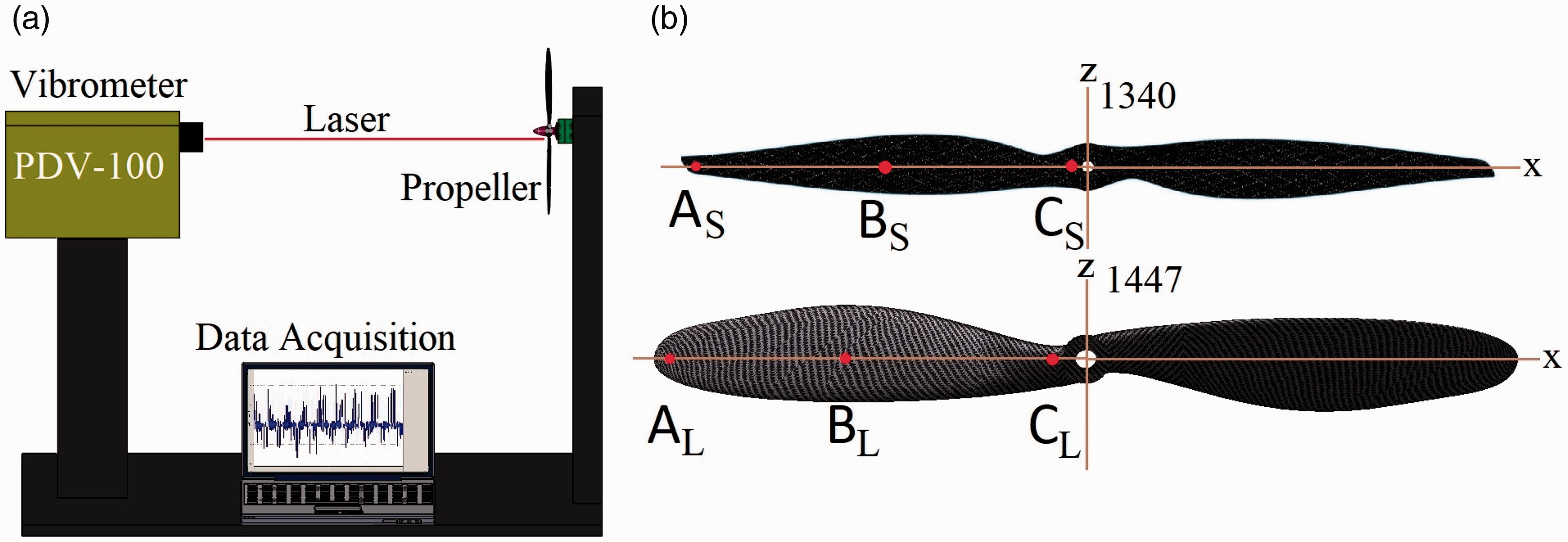
Propeller vibration measurement: (a) Equipment setup (b) Vibration test area.
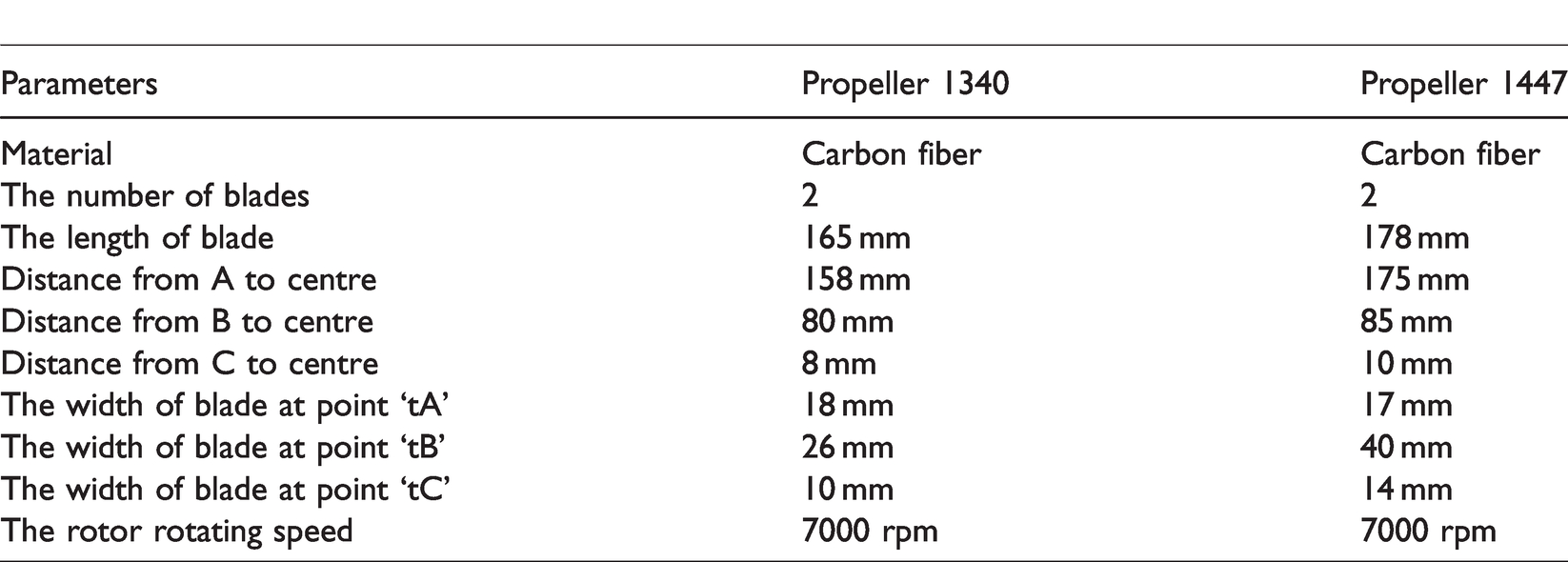
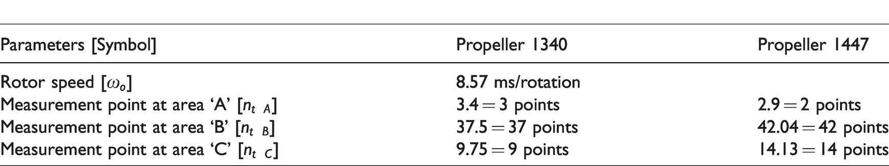
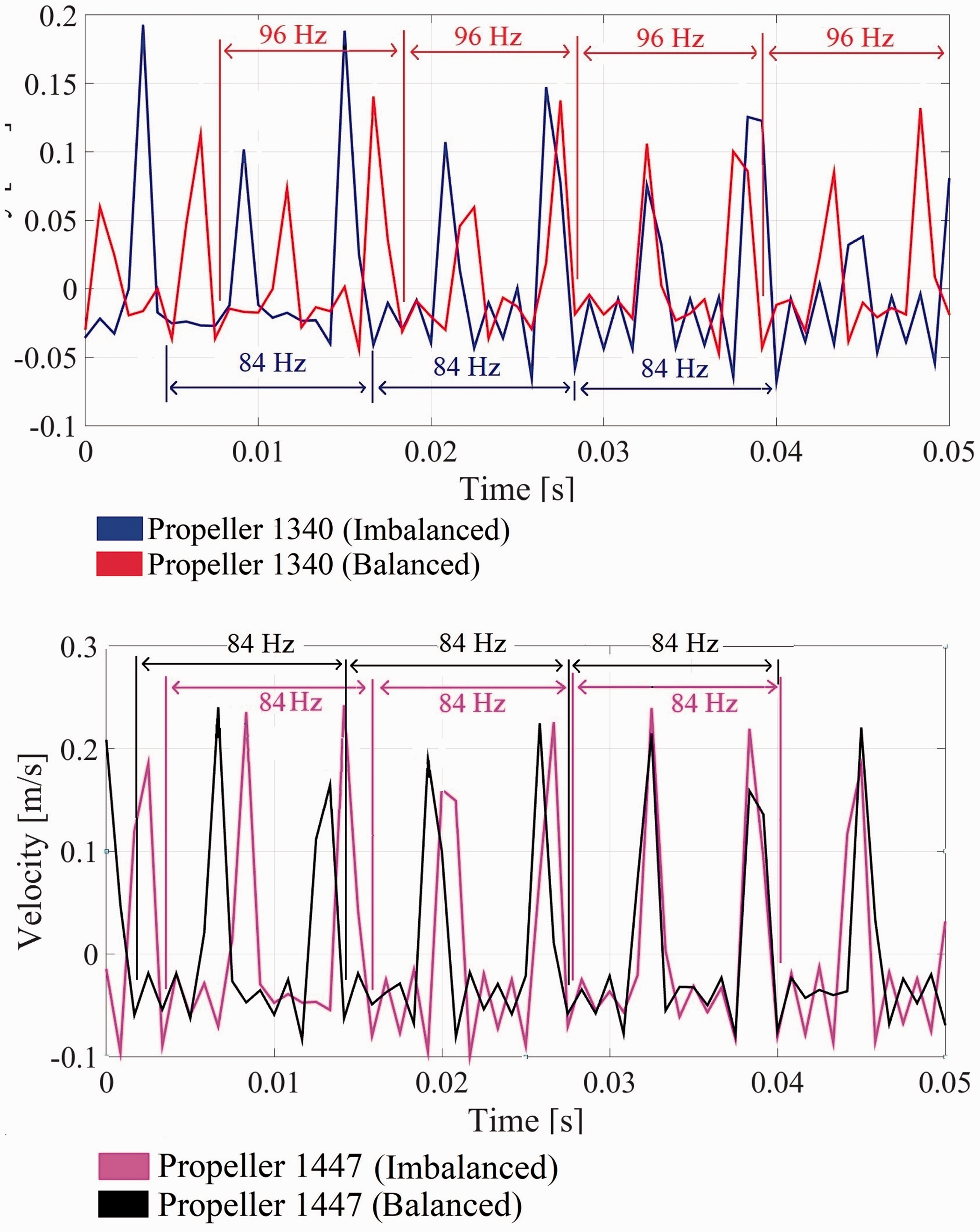
Propeller properties.
The contour of the surface affects the zero reference for the vibration velocity and the amount of amplitude generated is highly dependent on the propeller contour which corresponds to the pitch angle (q) and relative inflow angle (α). With the constant rotating speed at certain sampling time, the same vibration velocity pattern can be seen at each complete rotation. The propeller’s contour is presented in Figure 2.
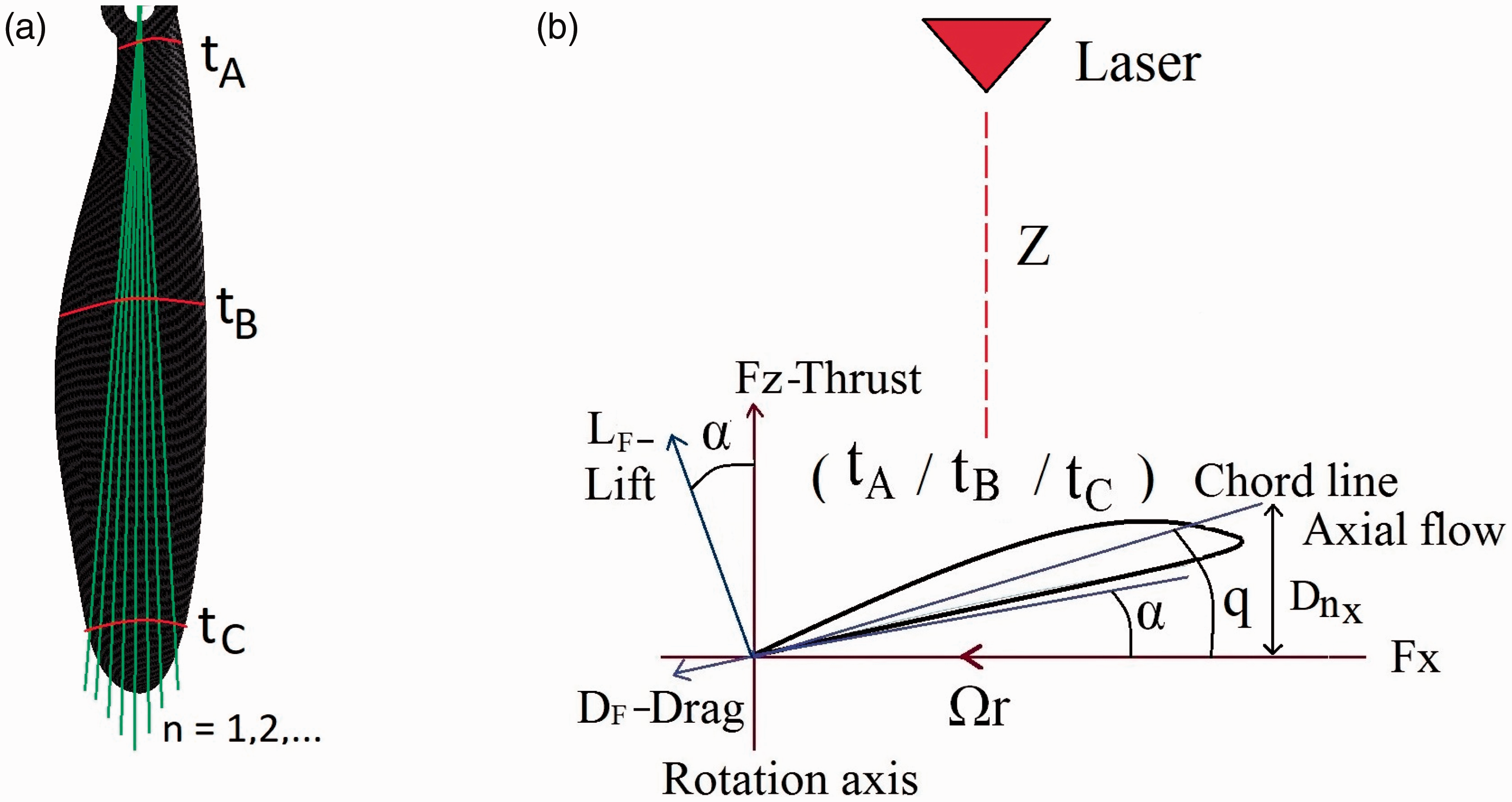
Propeller contour analysis: (a) Sample point on propeller (b) Correlations between contour propeller and laser position.
The propeller contour pattern can be obtained by measuring the distance between the laser beam source and each of the points (1…n) on the propeller’s surface (Z). The number of points which read during a complete rotation depends both on propeller angular velocity and data processing speed. The data acquired by the vibrometer will be easier to interpret using this contour pattern. The influence of each angle to the magnitude of generated thrust Lz, drag force DF, and lift force LF can be calculated using blade element theory.15,16 The vibrometer is in a static position and the propeller is in a dynamic state. Because the scanning process from laser vibrometer is faster than the propeller angular velocity, there is a “spacing” in which the laser does not read the value of propeller, as shown in Figure 3(a). To analyze the signal, it is important to know the number of points read by the laser on
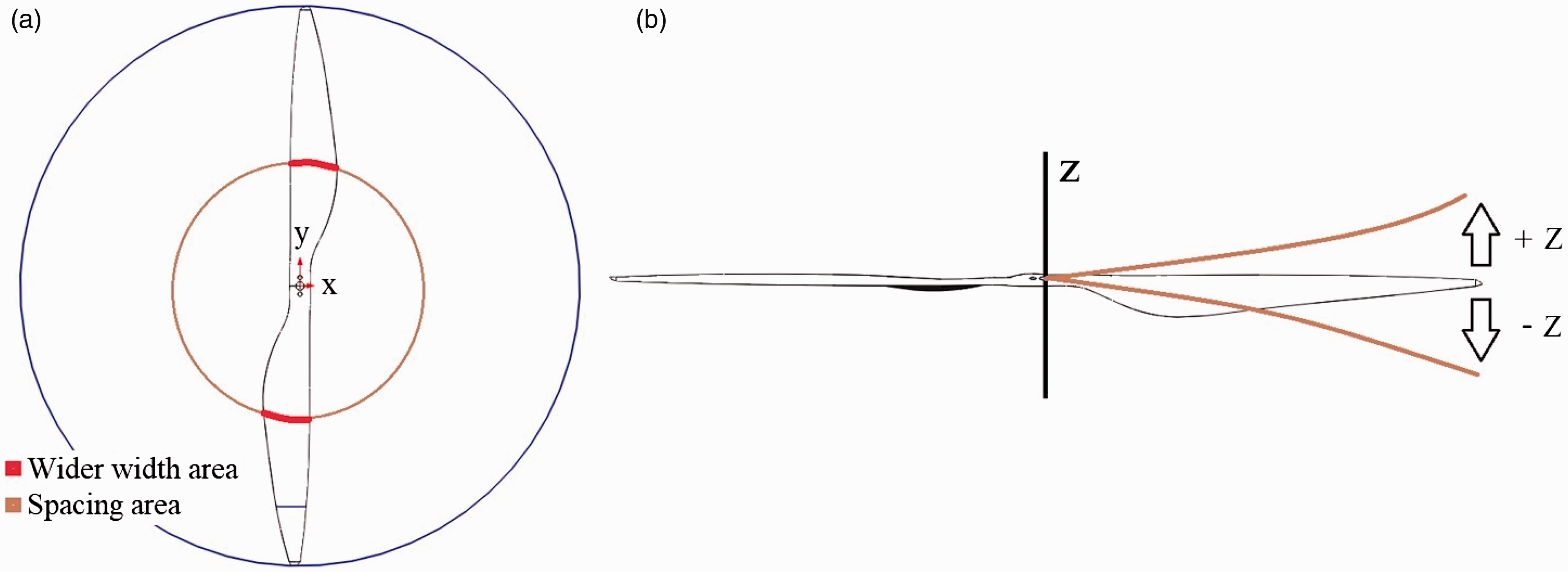
Propeller vibration measurement: Propeller illustration for (a) Measurement area (b) Appearance of vibration.
Propeller vibration measurement detail.
The velocity vibration will affect the value of arbitrary thrust along z-axis so that the resulting thrust will be smaller than the calculated value. The measurement area on the propeller and the illustration of vibration occurred can be seen in Figure 3.
A continuous over-vibration may break the propeller, especially the susceptible smallest part. To prevent this, the maximum rotation speed of each propeller was analyzed and overall will enhance the quadcopter stability.
Signal processing algorithm
Vibration velocity associated with a moving referential system is the function of vibration amplitude of the laser beam with time. There are various techniques in reading the frequency response produced by a laser vibrometer, depending on the application.17–19 To achieve the propeller’s vibration data, it is necessary to extract the characteristic features between vibration data and an unknown signal. This can be done using the blade vibration reconstruction algorithm.
20
In this analysis, the propeller rotation in clockwise and counter clockwise motion will cause zero reference differences so it can affect the positive or negative value of the vibration velocity produced. The propeller is rotating in a perpendicular plane to the laser vibrometer’s beam, and thus the number of points achieved for each of the contours depends on the propeller’s angular velocity and the data acquisition speed of the laser vibrometer. By using equation (1), the number of sample points read by the laser for a single rotation nt can be calculated based on the time needed for that rotation ω0.
The laser vibrometer has a maximum frequency of 22 kHz which gives a sampling time tlaser of 
The rotational angle can be calculated with equation (3) in which the blade’s width for each measurement path (
The number of sample points at each measured area for each blade can be seen in Table 3. These values are used in the initial calculation of the maximum rotor speed, used as a benchmark to separate the vibration data from the spacing data in the signal processing algorithm. Vibrational velocity is described by equation (4), where (wn) and (qn) are the characteristic function and generalized coordinate The total vibration on the propeller is effectively the result of amplitude modulation caused by for each vibrational mode (j) and each measured point (xn).21,22
Number of point on each area.
Since the laser vibrometer is stationary (considered in an Eulerian reference frame), both (wj) and (qj) are now functions of time. Consequently, vibrational velocity can be written as shown in equation (5). Since the propeller has a curve contour, a vibration algorithm with measurement position point on each sample is required to compare two or more complete rotation. All complete rotation must show the same pattern
From equations (4) and (5), the corresponding time and measurement position can be converted into discrete values as a response of the vibration vector as shown in equation (6)

The average-phase impulse response signal is subjected to a filtering process, using Matlab, thus avoiding phase distortion and also reducing noise or insignificant data. Based on the filtered data, the pattern of one complete rotation can be seen and comparison between the frequency response of a balanced and an imbalanced propeller can be made.
Propeller balance calibration
As the propeller’s axis of revolution fits perfectly to those of the motor’s shaft, and because the propeller is secured tightly, usually there is no vibration along x and y-axis (see illustration in Figure 2). When the propeller rotates at a particular velocity, it generates a downward force and as a result, propeller deformation may occur in the vertical direction. Thus, usually there is no vibration displacement on the x- and y-axis (see illustration in Figure 2). When the propeller rotates at a particular velocity, it generates a downward force and as a result, a vibration displacement may occur in the vertical direction. A vibration displacement is caused by the elasticity of the material used and the imbalance mass on each blade. Due to the centrifugal force generated by propeller rotation, the generated force by each blade must be equal. In this system, the static propeller balancing stand is used and is shown in Figure 4. The balancing concept of the propeller and rotor is similar; both are utilizing passive pendulum system. 22 The pivot points on both sides of the stand use magnet to eliminate the friction between shaft and stand. The balancing stand is designed to have the thrust vector at the center of each blade. There are two areas that need to be calibrated, i.e. the center of the blades and the hub.
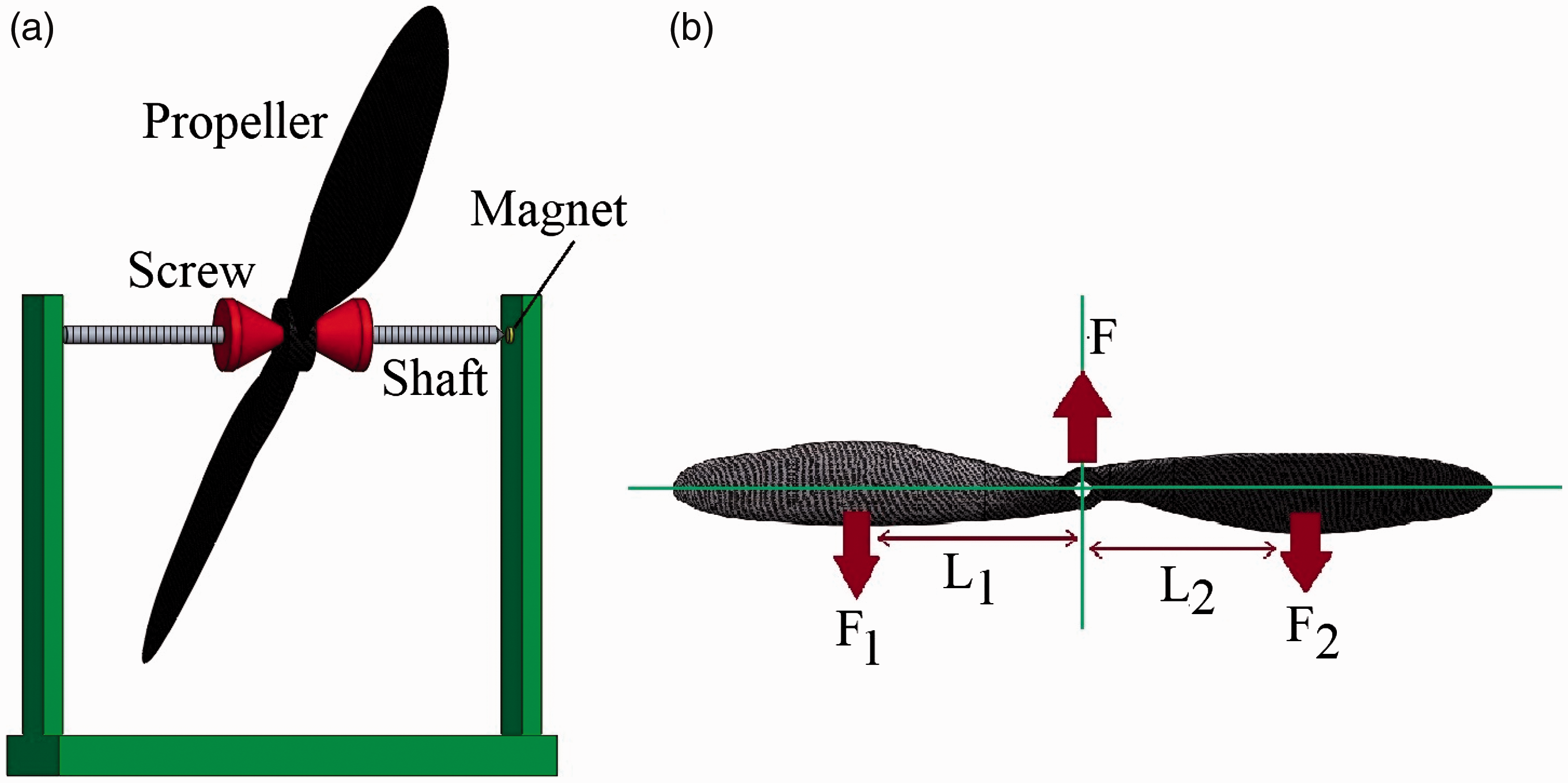
Propeller balancer: (a) Actual system (b) Force model.
In this research, both balanced and imbalanced models are analyzed to obtain vibration data. If the propeller is balanced, the centrifugal force described in equation (7) generated by each of the blades must be equal. In this case (F), the propeller runs smoothly and the generated centripetal acceleration is directed towards the centre of rotation. The centrifugal force depends on the propeller’s mass (m), angular velocity 

In the propeller balancer system, an imbalanced propeller occurs when one of the blades generate larger torque than the other. The correction factor (e) is the mass which should be added on one of the propellers according to equation (9). Equation (10) expresses the equilibrium of the moments generated by the blades after the mass (e) was added. The value of 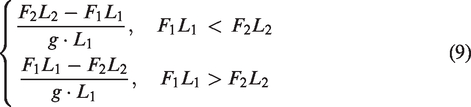

A balance state is achieved when the propeller can maintain a steady state in any position of the rotational area. If both blades become unsteady at a certain position and have a tendency to move in a certain direction, the addition of weight or removal of some part may be allowed on the blade or hub until both the blades reach equilibrium.
Experimental results and discussion
In this study, two different sizes of propellers are analyzed to observe their behaviors at the time of the vibration and to pinpoint the location of the largest vibration. Two measurement steps were done to observe the vibration behavior. The result was the comparison between the effect of a balanced and imbalanced propeller. Additional analysis was done to determine the correlation between rotor–propeller rotation speed and the vibration occurred. Both analyses require comprehension of measurement process related to the contour of propeller and point of measurement at the propeller.
The effect of balancing process towards propeller speed
The vibration measurements were performed on three points of the blade for two types of the propeller, with a sampling frequency 240 Hz and the maximum sampling time of 128 s. The laser vibrometer was set with a bandwidth of 0.1 kHz. The propeller was mounted on a rotor with the maximum angular velocity of 7000 rpm and rotated clockwise rotation. In the data collection process, the measurements began when the propeller reached the maximum angular velocity and is in a stable rotating state.
The vibration frequency response on each point is presented in Figure 5. This figure shows only 0.1 s sampling time of the total 128 s sampling time because the same pattern will appear repetitively on the same range frequency sampling. In order to properly analyze the result, the vibration value on the propeller was separated from the spacing value. The spacing value was obtained when the laser did not read the data on the propeller. At the center of the blade, the vibration velocity has the same pattern, and thus the propeller rotation speed was analyzed, as can be seen in Figure 6. From these data acquisition, the non-important data in form of spacing value were almost zero (0 m/s). With a sampling frequency of 240 Hz, the laser was only able to read one point on each blade. Based on the result’s in Figure 6, it can be noticed that the value of vibration velocity read by the laser was uneven because the sample points on the blade contour area were different on each rotation.
Vibration frequency response of non-balance propeller on: (a) Tip (b) Center of blade (c) Hub.
Vibration frequency response on the centre of the blade.
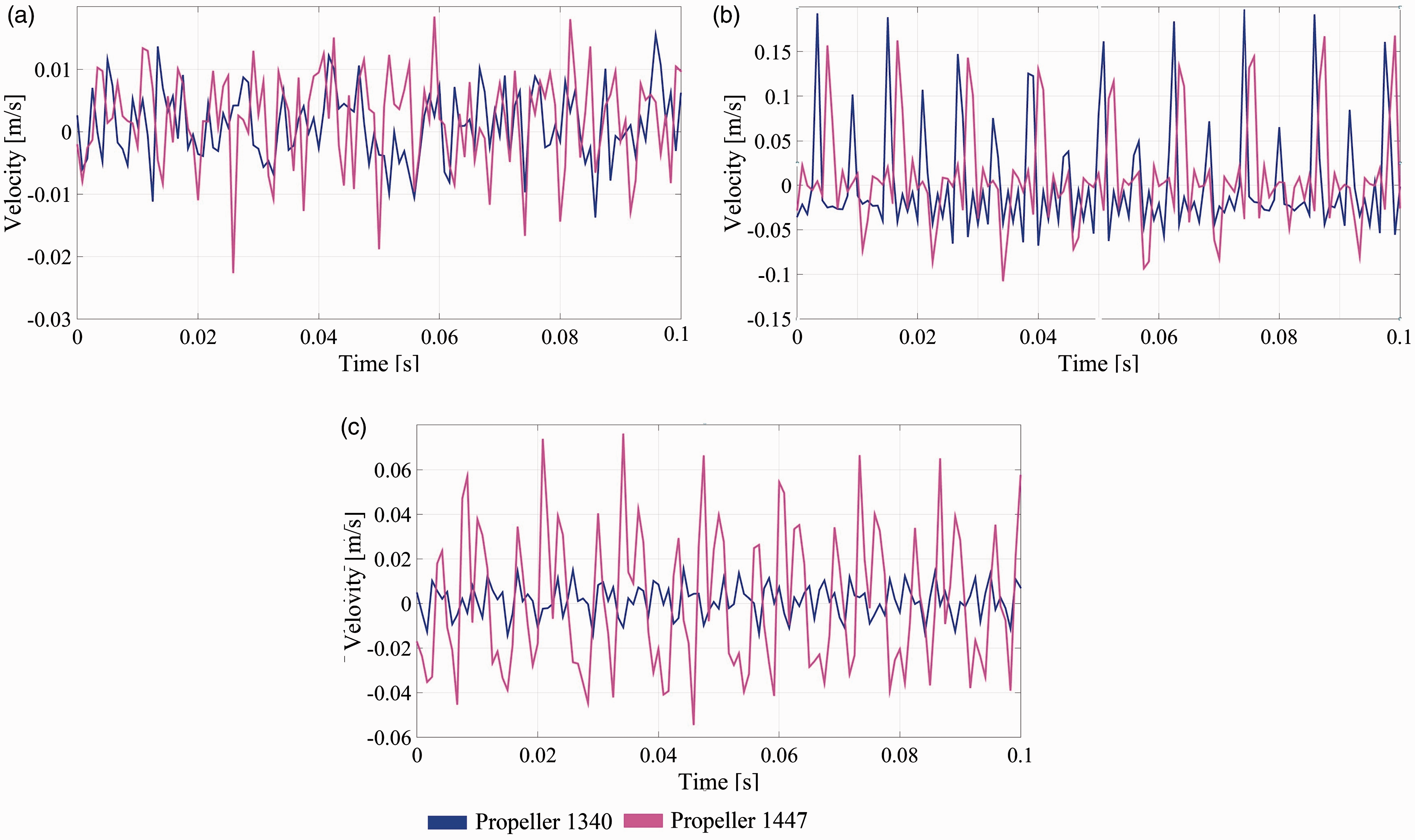
Correlation between vibration data and propeller contour pattern is given in Figure 7. The propeller contour caused the obtained vibration data to be unusable. To overcome this, the laser sampling frequency was increased. The distance between measured points depends on the laser sampling frequency and propeller rotation speed. This can be calculated with equations (2) and (3). For the 1340 propeller, the rotation imposed a sampling frequency of 96 Hz for a balanced model, and 84 Hz for an imbalanced model. For the 1447 propeller, there were no differences between an imbalanced and balanced model, and the sampling frequency was 84 Hz.
Illustration of propeller contour on the center of the blade.
The important vibration data associated with propeller contours were analyzed by filtering the insignificant data thus making the signal smoother. There were three data samples to be analyzed. Matlab toolbox analysis was used to filter the moving signal using a median filter
The same analysis method was used for each of the propeller’s hub, respective to each tip area. The results of scanning vibration for these points are presented in Figures 8 and 9.
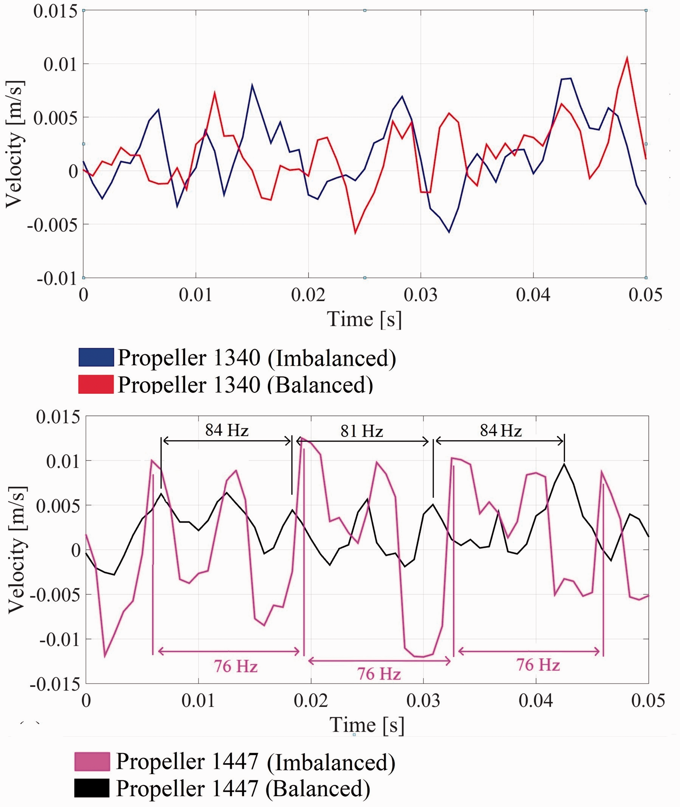
Vibration frequency response with filter on the tip of the blade.
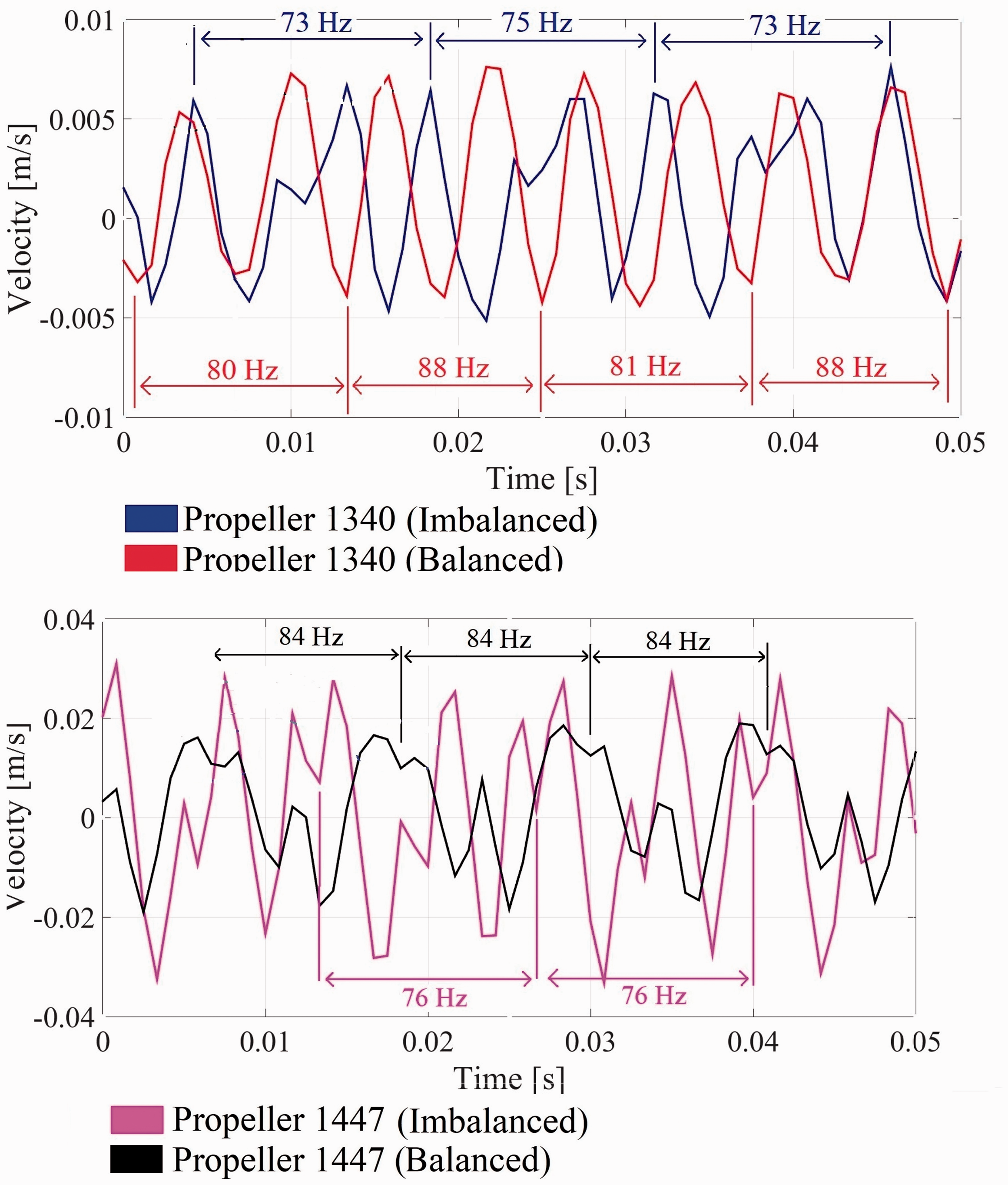
Vibration frequency response with filter on the hub of the blade.
Propeller 1340 has 10 mm of arc length at the tip of the blade and has an almost flat contour area, unlike propeller 1447. For a rotor having an angular velocity of 7000 rpm, Figure 9. The laser vibrometer cannot complete the scanning process to get the contour chord pattern. Compared with 1340 propeller, the 1447 model has a larger arc length of 14 mm, but its contour pattern can be read by a laser beam having the sampling frequency of 76 Hz for an imbalanced model and 84 Hz for a balanced model for one complete rotation. In the hub area, the propeller 1340 will yield to a smaller sampling frequency for the imbalanced model (73–75 Hz) compared to the balanced model (80–88 Hz), similar to the 1447. Because the experiment was performed with only one vibrometer for three zones of the point on the propeller, the sampling frequencies obtained were slightly different. From the data obtained, it can be concluded that propeller 1447 has an angular velocity of 5040 rpm for the balanced model and a lower angular velocity of 4560 rpm for the imbalanced model, whereas the propeller 1340 has a maximum angular velocity of 5280 rpm for the balanced model and 4500 rpm for the imbalanced model. In addition, a comparison between sampling frequency with the same contour area point was performed to determine the amount of error displacement.
Correlation between vibration and propeller rotation
Vibration velocity measurement on each propeller can only be done by maximizing the sampling frequency of laser vibrometer. The detail of measurement can be seen in Table 2. The goal of vibration measurement was to determine the propeller rotation speed limit to avoid over-vibration. Furthermore, vibration reduction will improve the quadcopter’s stability and optimize the thrust. The vibration measurement result for the balanced and imbalanced model of the 1340 propeller can be seen in Figure 10 and the result for the 1447 propeller in shown in Figure 11.
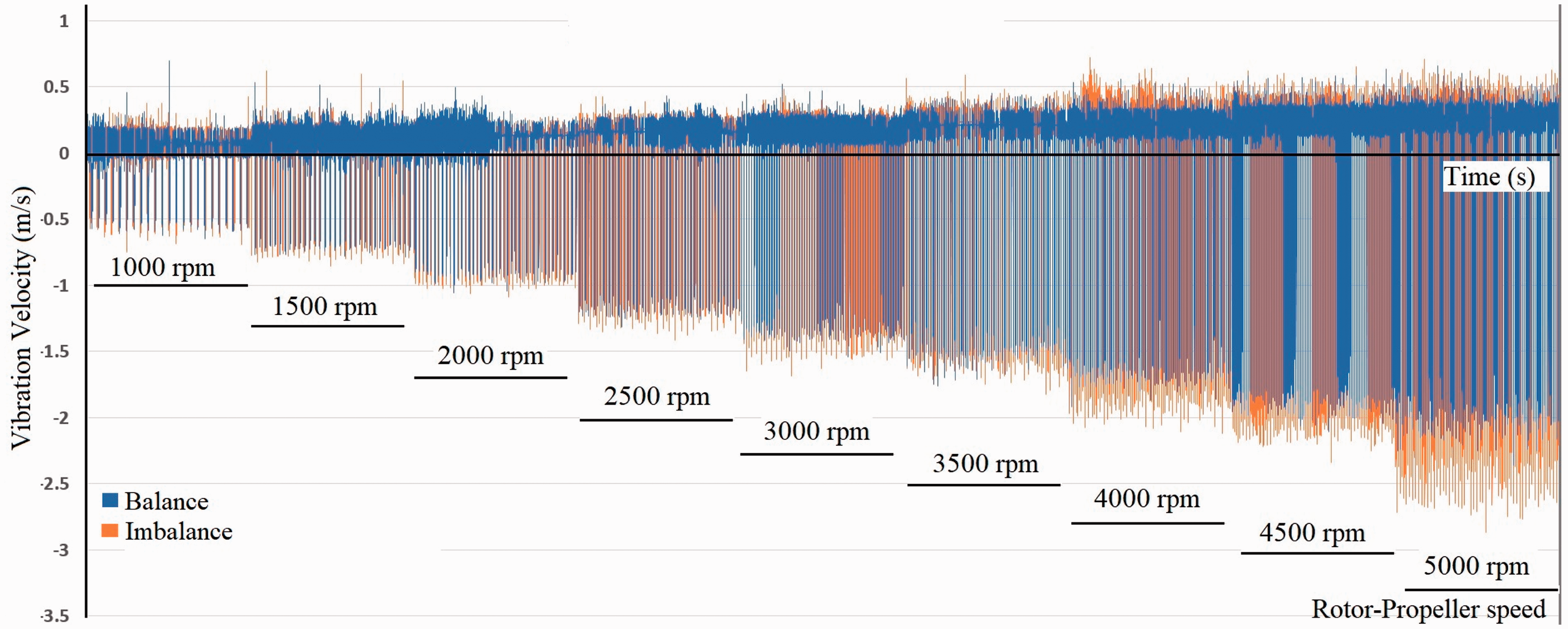
Vibration velocity with variant of speed on 13-inch propeller.
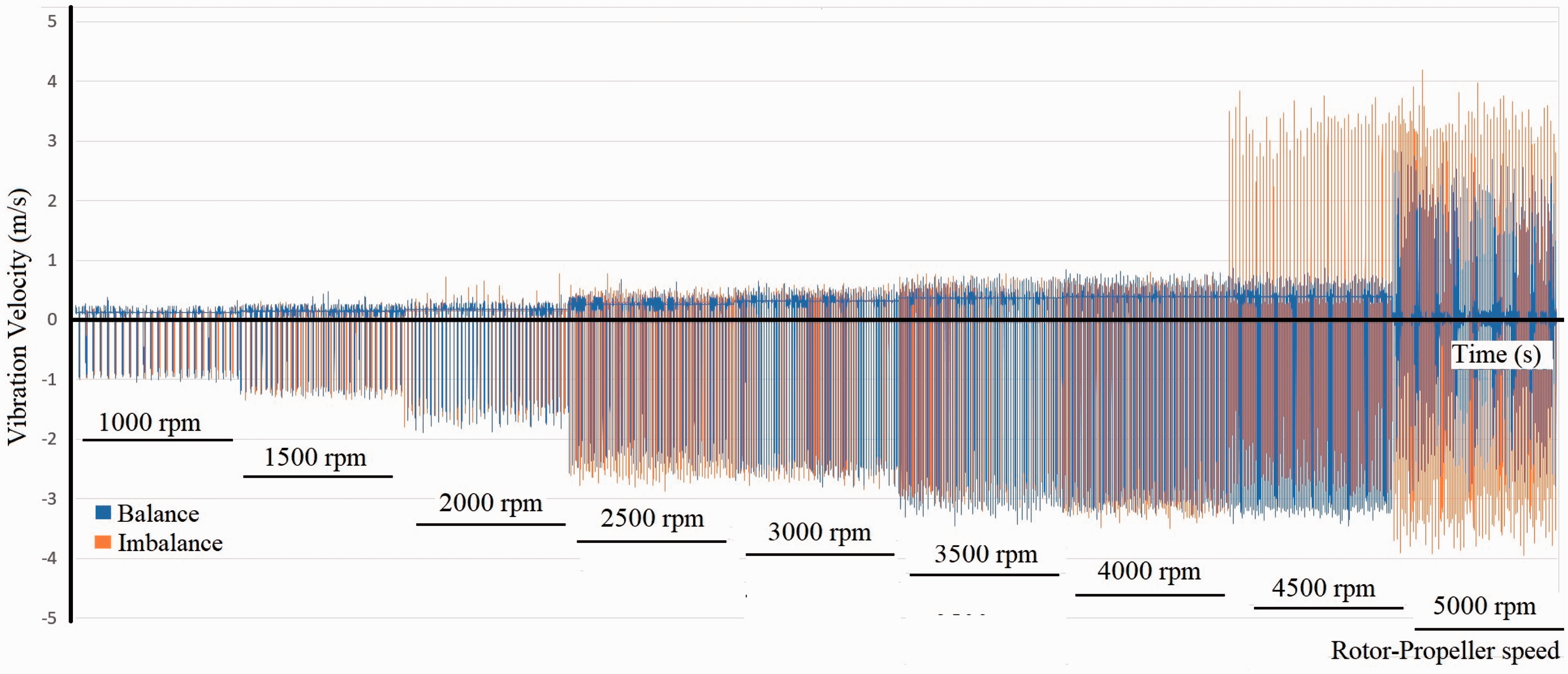
Vibration velocity with variant of speed on 14-inch propeller.
By increasing the laser sampling frequency, the number of sampling points on the blade area has also increased. The continuous propeller acceleration showed that the imbalanced model generated a bigger vibration velocity than the balanced model on both types’ sizes of propellers. The result of the vibration velocity average value at each rotation speed without contour effect can be seen in Figure 12.
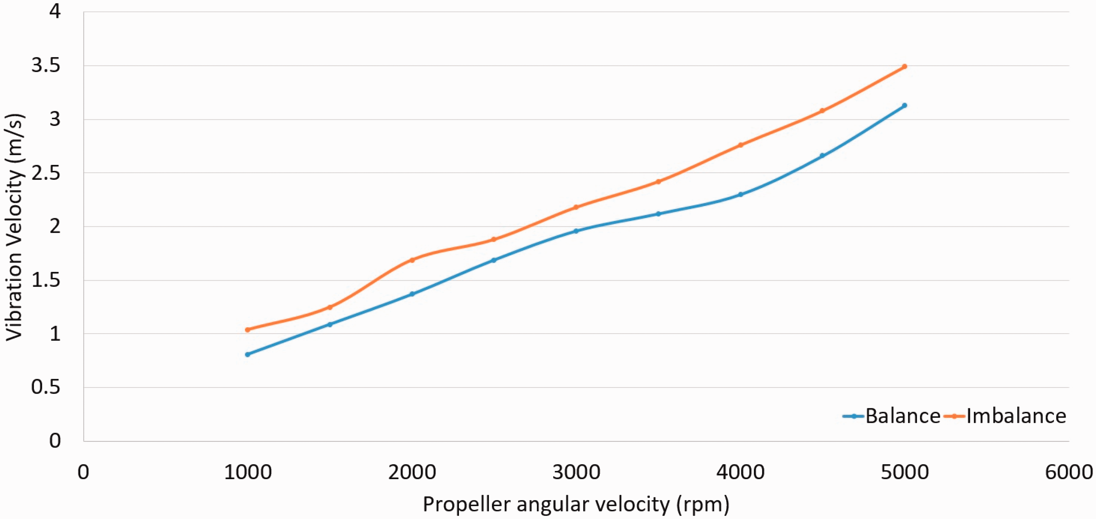
Vibration velocity result on 13-inch propeller.
The dependency of the vibration velocity with rotation speed can be seen in Figure 12. At the maximum speed of 5000 rpm, the vibration velocity was 3.1 m/s on the 14-inch propeller (see Figure 11). Significant vibrations values occurred at 5000 rpm propeller speed for the balanced model, and at 4500 rpm for the imbalanced model. Details regarding the propeller’s vibration velocity variation can be seen in Figure 13. By averaging the values of vibration velocity at each speed, it can be concluded that a dramatic increase in vibration velocity occurred over 4000 rpm. For the 14-inch propeller, the maximum rotation speed was 4500 rpm for which the vibration velocity was 4.2 m/s.
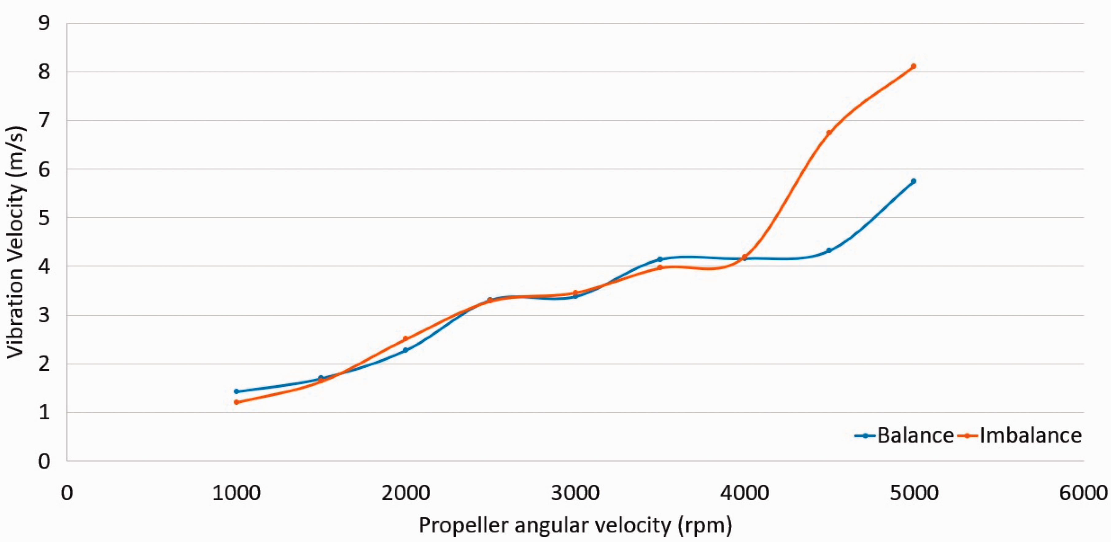
Vibration velocity result on 14-inch propeller.
It was not obvious to detect the propeller’s contour influence on vibration data. Equations (2) and (3) can only figure out the number of vibration points read by the laser beam from the blade area. This was due to the propeller’s small dimensions and insignificant blade contour angle as seen in Figure 7. By maximizing the laser sampling frequency, the number of sampling points was increased for each measurement and thus errors were reduced.
Conclusion
Problems raised by the unbalanced rotational movements have been widely investigated in the literature. Dynamic balancing, 23 respectively nonlinear behavior of unbalanced rotors24–26 in horizontal and vertical rotation planes, has been studied during the time. In this study, a non-contact laser vibrometer was used to measure the velocity of the vibration that occurs in the dynamic movement of the propeller. The contour pattern of the pitch angle on the propeller affected the frequency response pattern obtained from the scan result. The imbalanced model caused a decrease in angular velocity. A static balancer was used to adjust the weight of each blade to optimize the balance of the propeller. With rotor angular velocity of 7000 rpm, propeller 1340 generates a maximum speed of 5280 rpm and propeller 1447 generates a maximum speed of 5040 rpm. It was difficult to compare the propeller contour with the vibration data because the contour angle was not significant. To avoid differences in data retrieval area for each rotation, the laser sampling frequency must be at a maximum speed of 22 kHz. The vibration velocity occurred was linear with the propeller acceleration. The vibration was measured on the widest area on the blade which has the greatest air load. For a 13-inch propeller, there was no significant vibration and angular velocity of 5000 rpm generated a vibration of 3.1 m/s. On the other hand, a 14-inch propeller with an angular velocity more than 4500 rpm generated a vibration of 5.8 m/s, and thus 4500 rpm was determined as the velocity limit. The balancing process optimized the propeller rotation and reduced the vibration. Continuous vibration with huge velocity would break the smallest part of the blade. The rigidity of the blade material determined the vibration velocity limit. In the future, the effect of propeller material can be researched further and examine the vibration velocity limit on certain rotational speed.
Footnotes
Declaration of conflicting interests
The author(s) declared no potential conflicts of interest with respect to the research, authorship, and/or publication of this article.
Funding
The author(s) disclosed receipt of the following financial support for the research, authorship, and/or publication of this article: This work has been funded under the PNCDI III Programme P2 – Transfer of knowledge to the economic operator (Bridge Grant PN-III-P2 2.1 BG-2016–0296) funded by UEFISCDI, Romania.