
Abstract
In Chinese metro lines, Vanguard fastener system is widely used as vibration damping fastener. However, the rails mounted with this fastener system are deeply affected by rail corrugation. The generation mechanism of corrugation wear at a metro track mounted with Vanguard fastening is revealed through the numerical simulation method. A finite element model including two rails, the track system, and a leading wheelset is set up. The parameter sensitivity analysis is conducted to identify the dominant factors affecting the rail corrugation. Then, the remedy method to suppress the corrugation wear is put forward on the basis of the parameter analysis results. The results indicate that the severe corrugation wear on the inner rail is attributed to the self-sustained vibration of the wheelset–track system aroused by the saturated wheel–rail creep force. The frequency of the rail corrugation calculated by the model is very close to the measured data. The elastic modulus and the damping coefficient of the rubber rest pad in the Vanguard fasteners have a high impact on rail corrugation. Increasing the elastic modulus and the damping coefficient can effectively restrain or even eliminate the rail corrugation. Bringing the damping coefficient of the rubber rest pad above 0.0001 can significantly alleviate the rail corrugation. The influence of the damping and stiffness of the rubber pad under the floating slab track bed is negligible.
Introduction
The characteristics of high speed, high volume, punctuality, safety, and environmental friendliness make the urban subway system the first choice to alleviate urban traffic congestion. However, the rapid growth of subway lines also brings vibration and noise, and affects the residents along the lines as well as vibration-sensitive buildings and equipment. To alleviate the vibration and noise of the subway system, some vibration damping fastenings, such as Cologne-egg fasteners and Vanguard fasteners have been used in China’ subway lines. However, after installing the subway lines with these fastener systems for a period of time, rail corrugation appeared on rails.1,2 Slight rail corrugation can cause wheel–rail noise, vibration, and fatigue of structural components of vehicle and track. Therefore, the service life of vehicle and track will be shortened. However, serious rail corrugation will threaten the safe operation of trains. Vanguard fastener system is mainly used in the curved track. After a period of operation of a subway track with Vanguard fasteners, serious rail corrugation appeared on the inner rail surface. As shown in Figure 1, the gloomy area on the inner rail surface is the trough of the corrugation wear, while the bright area is the crest. The wavelength of the corrugation wear is in the range of 30–70 mm. However, there is no obvious corrugation wear on the outer rail surface. At present, the cause of the formation of the corrugation wear on the track mounted with Cologne-egg fastening has been fully studied.3–5 But there is a serious shortage of research on the initiation and evolution and remedy method of corrugation wear on the rail installed with Vanguard fasteners.
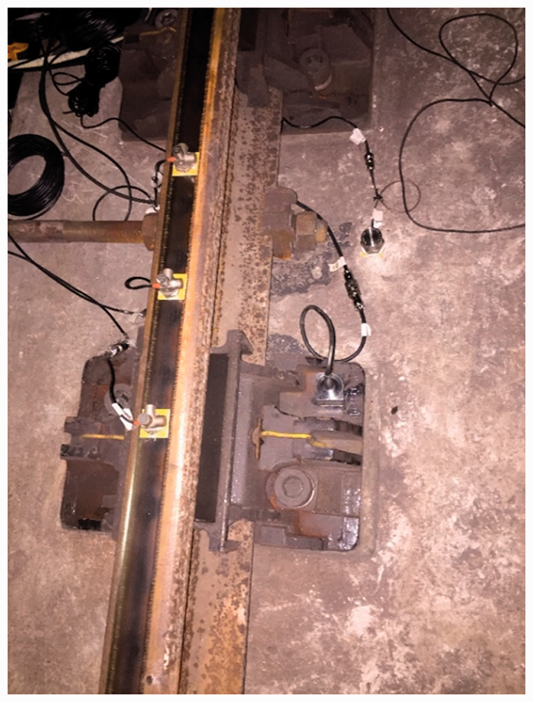
Rail corrugation on the rail mounted with Vanguard fasteners.
Rail corrugation is a very complicated and detrimental problem in railway engineering. For decades, many scholars and researchers have done an enormous amount of researches on corrugation wear. Based on the wavelength fixed mechanism and the material removal mechanism, rail corrugation can be divided into six types. 6 Among them, the formation mechanism of the short-pitch corrugation is still uncertain, and has perplexed many researchers for several decades. The existing formation mechanism of corrugation wear falls into two categories: (1) corrugation is a consequence of the fluctuation of friction work due to the transient dynamic vehicle–track interaction7–9 and (2) the stick-slip vibration on the wheel–rail contact interface is responsible for the corrugation wear.10,11 Based on these two theories, some countermeasures are developed to suppress rail corrugation, such as tuned rail vibration absorber12–14 and friction modifier.15,16 However, these existing theories cannot explain satisfactorily some perplexing features of corrugation wear. For example, in the first type of theory, it is assumed that there is an initial irregularity on the rail surface. When the wheelset is rolling on the rails, the resonance of the vehicle–track system at some specific frequencies is excited, which causes the friction work on the wheel–rail contact interface to fluctuate at the same frequency. The fluctuating friction work will lead to nonuniform wear on the surface of rails, as a consequence of which rail corrugation is created. Interestingly, the model established based on this theory also generates rail corrugation under an input of a white-noise roughness. 8 However, the white-noise roughness on the rail surface is ubiquitous, which means that all rails in the straight track and the inner and outer rails of a curved track will be affected by corrugation wear. Apparently, the theory cannot explain an extremely common phenomenon of rail corrugation: when the curve radius R < 350 m, 100% of the inner rail will be subjected to corrugation wear. But corrugation wear on another rail of the same track is not obvious and almost invisible to naked eyes. When the curve radius is R > 650 m or in a straight track, rail corrugation rarely appears on neither the inner rail nor the outer rail of the track. Even if rail corrugation occurs, there is also a strong uncertainty that cannot be predicted. Obviously, this theory cannot explain the above rail corrugation phenomenon. In the second type of theory, stick-slip vibration between the rail and the wheel is believed to be the cause of corrugation wear. However, the frequency of the rail corrugation predicted by the model based on this theory is in the range of 20–80 Hz, 11 which is remarkably lower than the actual frequency.
Aiming at the weakness of existing theories in explaining these corrugation phenomena, Chen 17 proposed a theory of friction-sustained vibration between the track and the wheelset causing corrugation wear of the rail. The theory holds that when the wheelset negotiates a sharp curved track, the large attract angle and the lateral displacement cause the wheel–rail creep force to tend to saturation, thus resulting in the wheelset sliding on rails. Then, the frictional self-sustained vibration between the wheelset and the track will be excited easily by the wheel–rail friction force. Finally, the rail corrugation will be created. Shortly afterwards, Kurzeck and Hecht18,19 also carried out similar researches. In recent years, a variety of rail corrugation in subway lines have been deeply studied by Chen’s research group, and these complicated rail corrugation phenomena have been reproduced successfully using the theory.20–25 Also, Omar 26 in Milan polytechnic university completed the main research work of his dissertation based on Chen’s theory. The results from his dissertation are consistent with the actual rail corrugation.
The paper is aimed at studying the origin and countermeasures of the corrugation wear occurring in the subway rail mounted with Vanguard fasteners through numerical simulation. A friction-induced vibration finite element model including two rails with Vanguard fasteners system, a leading wheelset, and track slab is established. The distribution of the unstable frequencies and their equivalent damping ratios are studied using the complex modal analysis method. The dominant factors affecting the rail corrugation are identified through the parameter sensitivity analysis to develop some countermeasures against the corrugation wear. The results reveal that the saturated creep force between the rail and the wheel is the cause for the severe corrugation wear at the sharp curve track mounted with Vanguard fasteners. The wavelength of the rail corrugation is 51.4 mm, which is very close to the actual wavelength. Increasing the modulus of elasticity and damping coefficient of the rubber rest pad of Vanguard fasteners can effectively suppress or even eliminate the rail corrugation.
Numerical simulation model and theoretical method
Finite element model of the wheelset–track system
In this paper, the theory of frictional self-sustained vibration is used to analyze the formation mechanism of the corrugation wear. A finite element model including the rails with Vanguard fastener system and a leading wheelset is set up. The wheelset–rail interaction model is shown in Figure 2. The track system consists of rails, the track slab, and Vanguard fastener system. The rubber vibration damper plate under the track slab is simplified as a series of grounding dampers and springs distributed evenly on the bottom of the track slab, whose vertical damping and stiffness are CSV and KSV, respectively. As shown in Figure 2, the outer wheel–rail contact point is located between the rail profile and the wheel flange, while the inner wheel–rail contact point is located between the rail head and the wheel tread. The contact angles on both sides of the wheelset are δL and δR, respectively. The normal contact forces on both sides of the wheelset are NL and NR, respectively. FL and FR are wheel–rail creep forces on both sides of the wheelset, respectively. The contact angle δL is 27.51° and δR is 1.18°, which are calculated by the multi-body dynamic software Simpack. The primary suspension forces are FSVL = 41,000 N, FSLL = 2400 N and FSVR = 37,000 N, FSLR = 2400 N, respectively. The curve radius is 390 m.
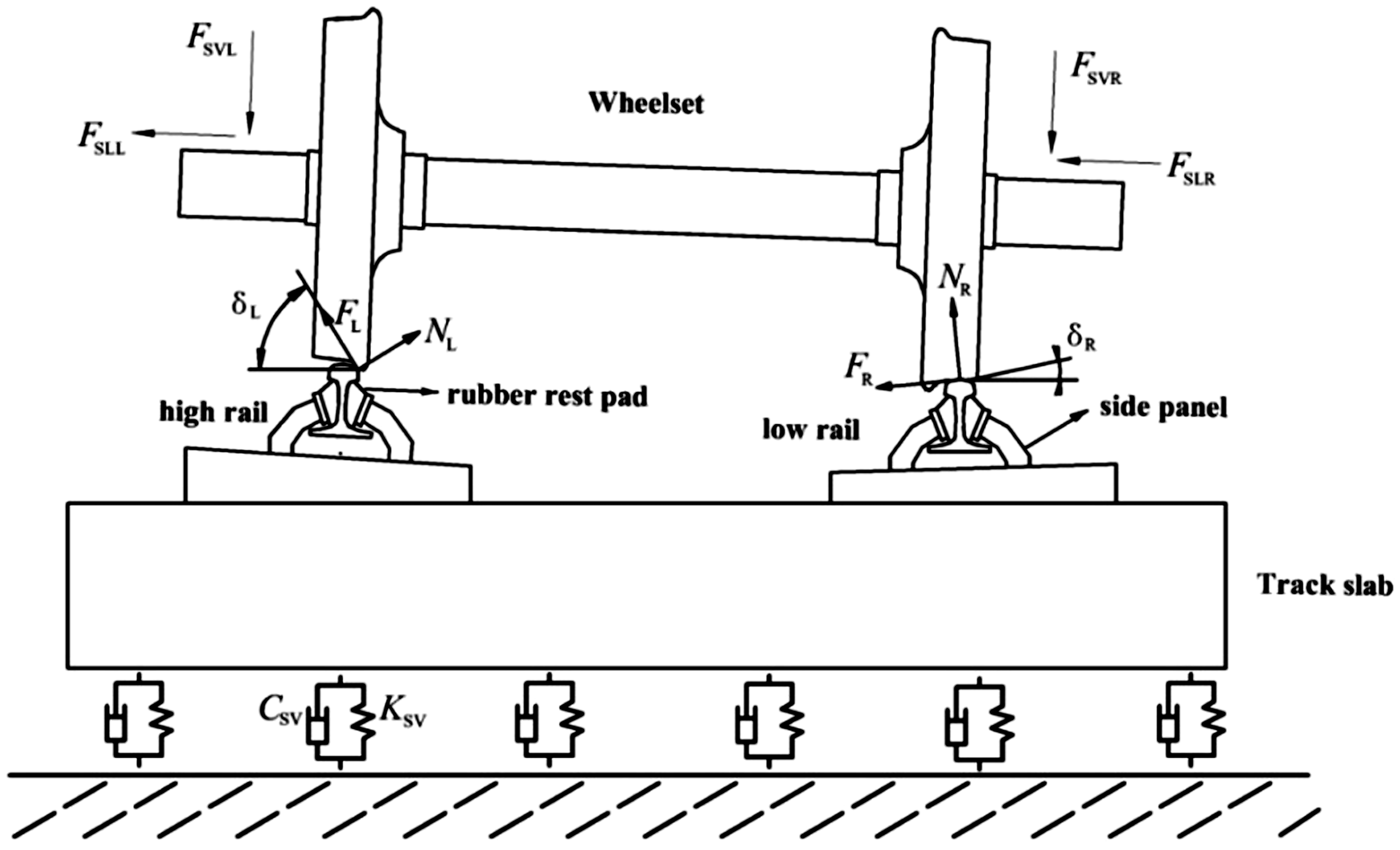
Wheel–rail interaction model at a sharp curve track with Vanguard fasteners.
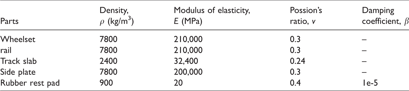
Figure 3 shows the finite element model of the wheel–track system. The wheelset is located in the middle of rails so that the effect of the fixed boundary condition at the end rails on the simulation results can be mitigated. The track length is taken as the span length of 60 fasteners according to literature 20 and the track span is 625 mm. The massless springs and dampers simplified from the rubber vibration damper plate are distributed evenly on each node at the bottom of the track slab. The track cant is 1:40. The nominal radius of the wheelset is 840 mm, with a worn tread. The contact relationships between the wheelset and the rail and between the rail waist and the rubber rest pad are established in the model. The Coulomb model of friction is adopted to describe the friction between wheel and rail, and between the rail waist and the rubber rest pad. Although in subjects like earthquake modeling and brake squeal, where experimental validation studies have been carried out, it has been found that the Coulomb model rarely if ever gives reliable predictions of the actual measured instabilities. However, the validity of the Coulomb model of friction is verified by the experimental tests when studying the unstable vibration of the wheel–rail system.3,21,27 The wheel–rail friction coefficient is 0.3, the coefficient of friction between the rubber rest pad and the rail waist is 0.75. The 8-node incompatible solid element is used to mesh the model. The model contains 629,617 solid elements, 9963 damping elements, 9963 spring elements, and 897,020 nodes. The linear elastic material model adopted in the model, and their parameters of material are shown in Table 1.
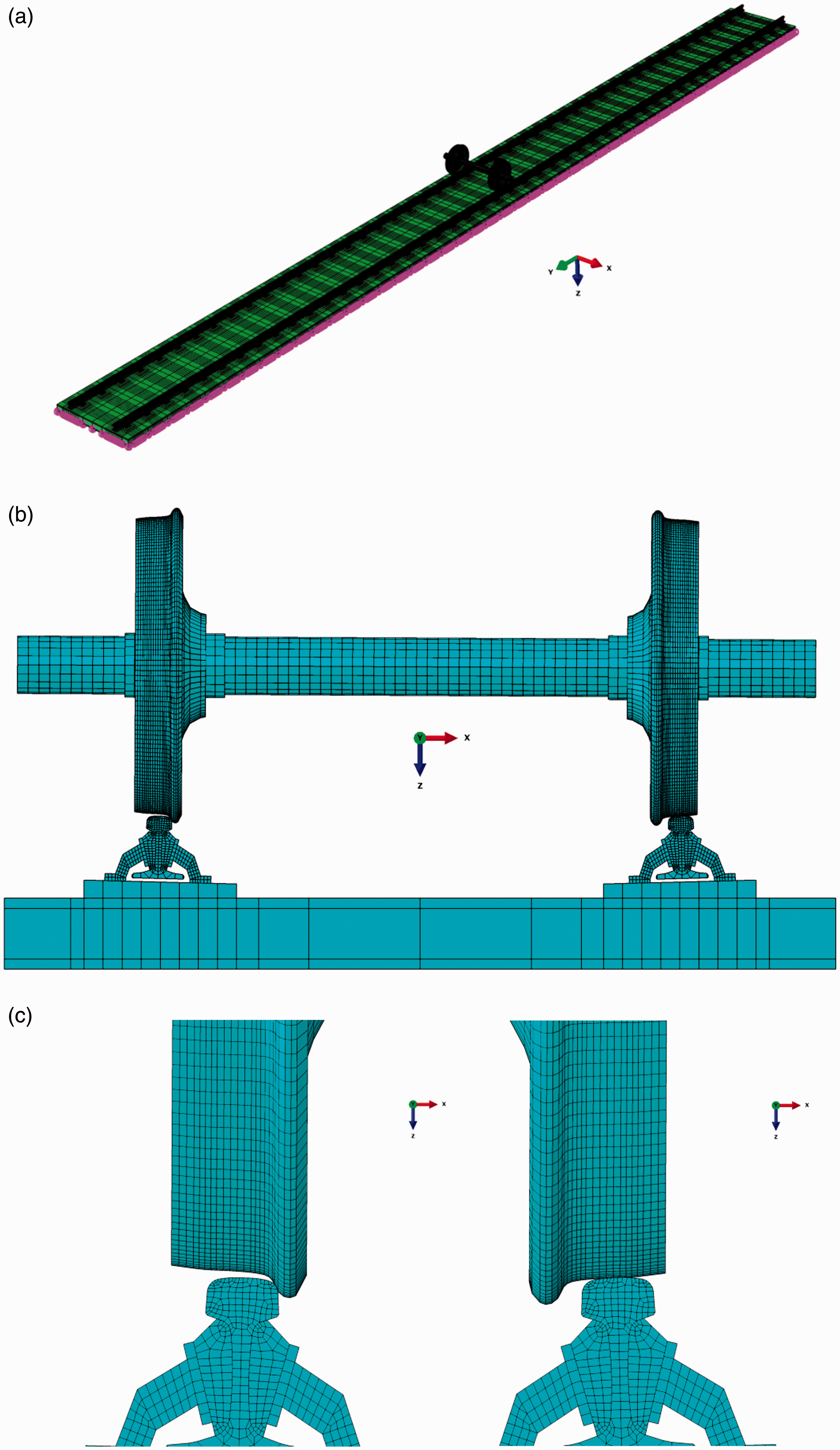
The finite element model of the wheelset–track system at a sharp curve track with Vanguard fasteners: (a) the whole model; (b) the front outline; (c) the wheel–rail contact details.
Parameters values of material of the wheelset–track system.
Multibody dynamic model of the vehicle–track system
The location of contact points, the creep force between the rail and the wheel, and the distribution of the primary suspension force have a high impact on the frictional self-sustained vibration between the track and the wheelset. To accurately determine the wheelset–rail contact positions, the contact angle, and the wheel–rail creep force, a multirigid body dynamic model of the track–vehicle system is established using the dynamic software Simpack, as shown in Figure 4. In the model, the vehicle is composed of a car body, two bogies, and four wheelsets, in which wheelset 1 and wheelset 3 are the leading wheelsets, and wheelset 2 and wheelset 4 are the trailing wheelsets. The curve radius is 390 m and the outer rail superelevation is 0.119 m. The total length of the curve track is 900 m, including straight line, circular curve, and transition curve. The speed of the vehicle passing through this subway section is 59 km/h. Parameters such as vehicle size, suspension system stiffness, and damping are referenced from Li et al. 28
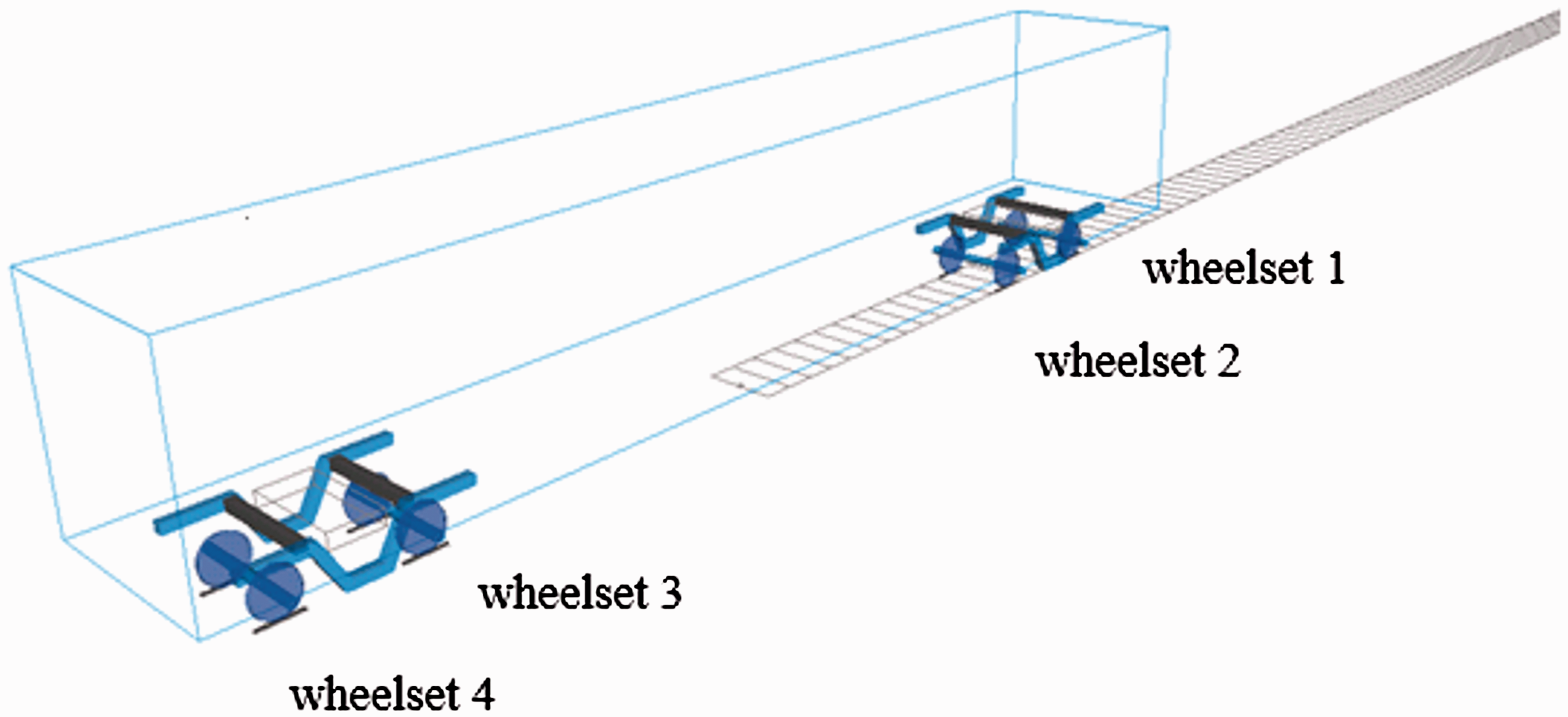
Multirigid body dynamic model of the vehicle–track system.
Theoretical basis of complex mode analysis
The complex modal analysis method of ABAQUS code is used to analyze the vibration frequencies and modes of the wheelset–track system, whose theoretical basis is as follows.
17
First, the motion mode of the wheelset–track system is expressed by the following matrix equation

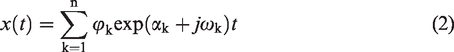
Due to the friction, the stiffness matric and damping matric of the motion equation (1) are asymmetric matrices. For the equations of motion with asymmetric stiffness matric and damping matric, the solution can be expressed as follows

Analysis of the corrugation wear
When studying the origin of the short-pitch corrugation wear, a commonly accepted assume is that its material removal mechanism is uneven wear on rail surface caused by the fluctuating friction work between the rail and the wheel. Any factors that cause friction work fluctuation are the potential causes of rail corrugation. In this section, corrugation wear will be related to the self-sustained vibration between the track and the wheelset through the fluctuating friction work. Brockley proposed proposed a wear model
29

Results and discussion
Analysis of saturated creep force
The prerequisite of the theory of the self-sustained vibration between the rail and the wheel causing corrugation wear is that the wheel–rail creep force becomes saturated. To determine whether this premise is satisfied in the case studied in this paper, the creep forces when the vehicle negotiates this sharp curved metro track are analyzed using the dynamic software Simpack. The saturation of adhesion is used as an index to determine whether the creep force is saturated in Simpack, which is defined as

Figure 5 shows the saturation of adhesion of the two wheelsets of the front bogie when the vehicle negotiates the curve track. As shown in Figure 5(a) and (b), the saturation of adhesion of wheels on both sides of the leading wheelset approach 1 in the circular track section, which means that the creep forces of the leading wheelset are saturated, and the wheelset will slide on the rails. As is shown in Figure 5(c) and (d), the saturation of adhesion of the wheels on both sides of the trailing wheelset are far less than 1 in the whole curve section. So, it can be considered that the creep forces of the two rear wheels are not sarturated. The saturation of adhesion of the wheels of the rear bogie are similar to that of the front bogie. Due to the limitation of space, the results are not given here. Obviously, the premise is satisfied in the case studied in the paper. According to the fact that the creep forces of the leading wheelset are saturated and that of the trailing wheelset are not saturated, only the influence of the leading wheelset is considered in the finite element model.
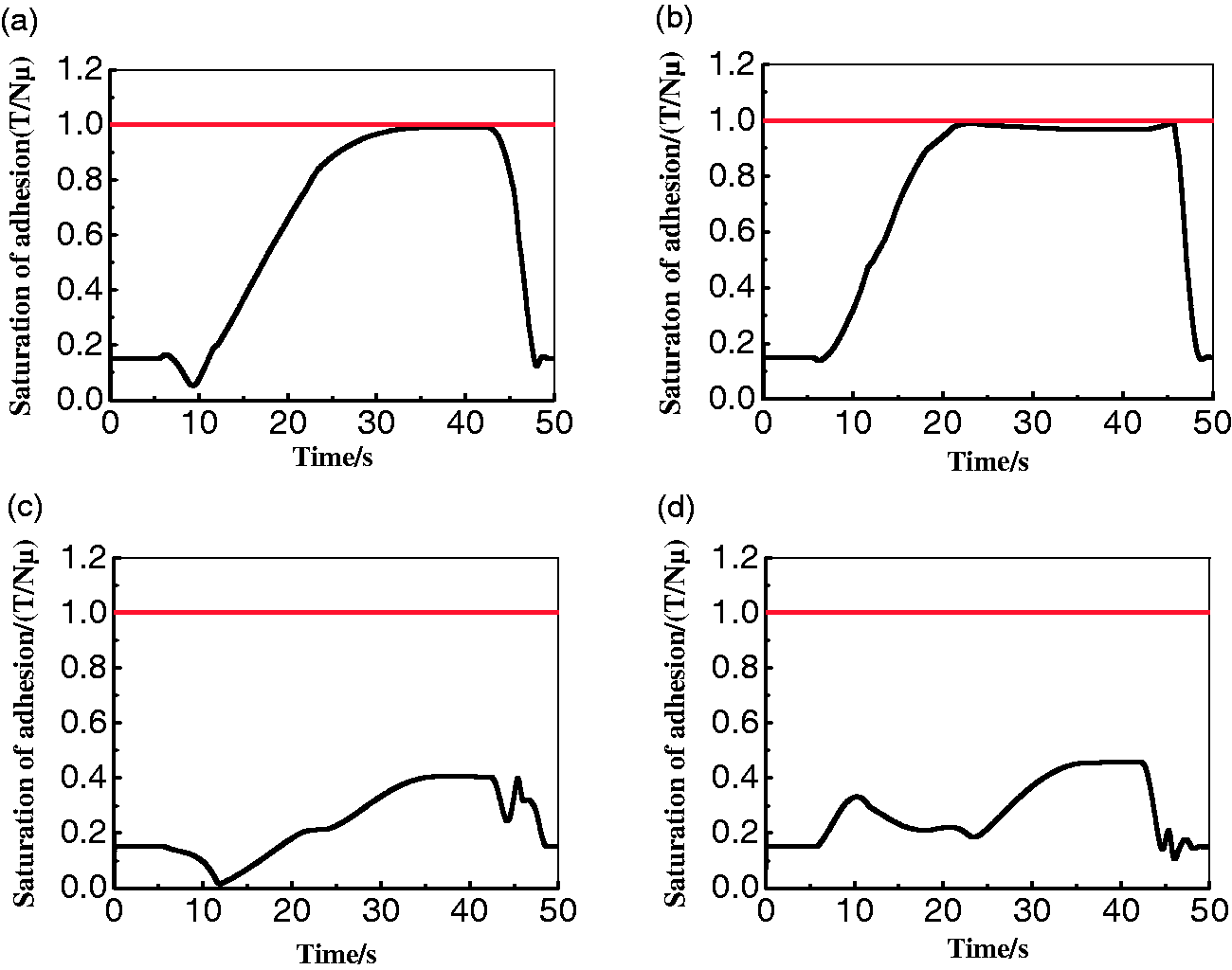
Curves of the saturation of adhesion of the front bogie when a train negotiates a curve track; (a) the outer wheel of the leading wheelset; (b) the inner wheel of the leading wheelset; (c) the outer wheel of the trailing wheelset; (d) the inner wheel of the trailing wheelset.
Self-sustained vibration modal analysis of the wheelset–track system
The wavelength of the corrugation wear occurring at the curve track installed with Vanguard fasteners is in the range of 30–70 mm, the speed of the vehicle passing through this subway section is 59 km/h, and the corresponding corrugation frequency falls in the range of 234–546 Hz. Therefore, this paper studies only the self-sustained vibration in the range 20–800 Hz. Figure 6 shows the frequency distribution of the self-sustained vibration between the rail and the wheel. As shown in Figure 6, there are eight unstable vibration frequencies, among which the unstable vibration with a frequency of 319 Hz has the smallest effective damping ratio of −0.0152, which is the most likely unstable vibration. The wavelength of corrugation wear caused by that unstable vibration with a frequency of 319 Hz is about 51.4 mm, which is very close to the measured data. Figure 7 is the corresponding vibration mode of this unstable vibration. As shown in Figure 7, we can see that the vibration at 319 Hz mainly occurs in the inner rail and the inner wheel of the wheelset, which means that the corrugation wear caused by the unstable vibration at 319 Hz will mainly appear on the inner rail, which is consistent with the reality. The effective damping ratios of the other unstable vibrations are greater than −0.001, which are not enough to overcome the system damping to cause the corrugation wear.
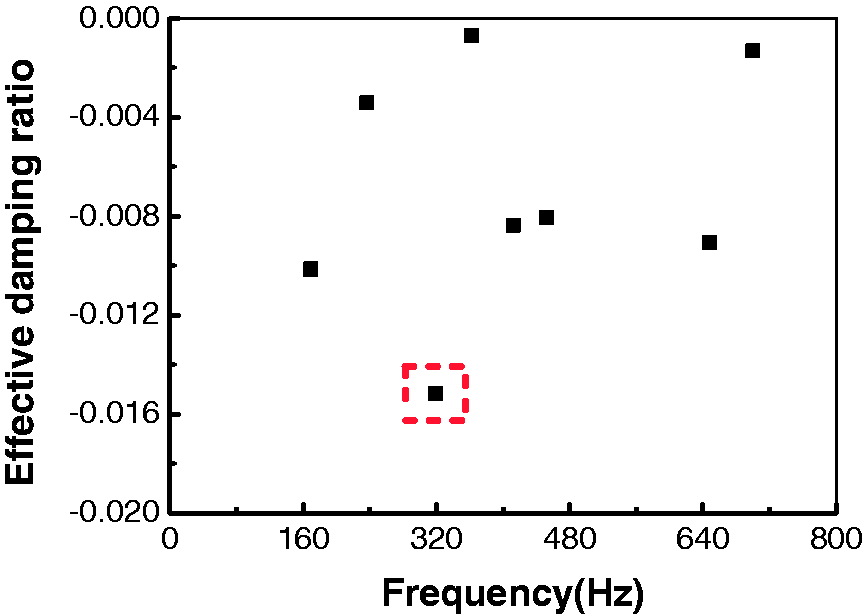
Distribution of the frequencies of the self-sustained vibration between the wheelset and the track with Vanguard fasteners.
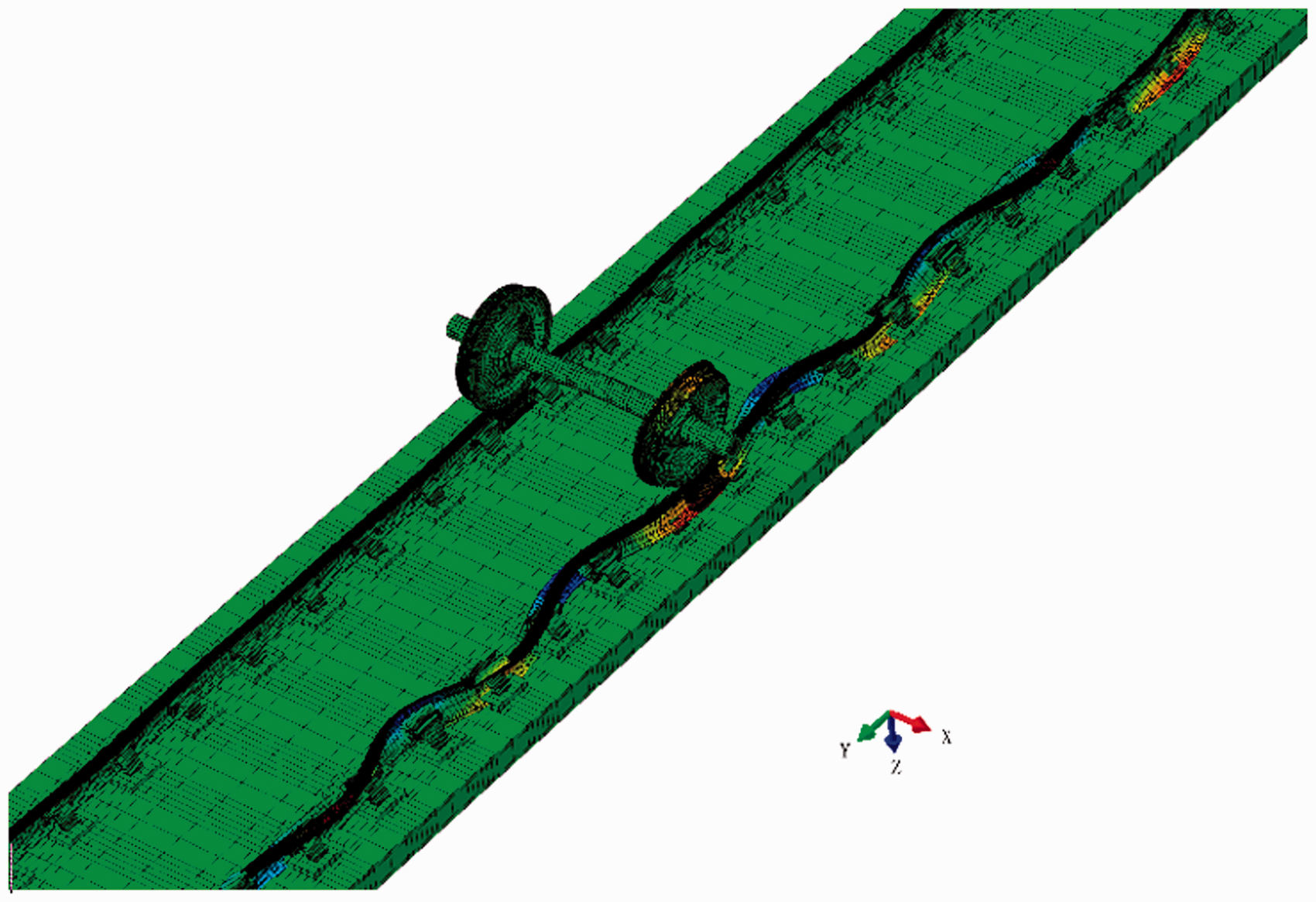
Mode shape of the self-sustained vibration between the wheelset and the track with Vanguard fasteners: fR = 319 Hz, ζ = −0.0152.
Effect of the elastic modulus of the rubber rest pad on the self-sustained vibration between the track and the wheelset
With its special features, while achieving vibration isolation, Vanguard fastener also brings severe rail corrugation. Because of its low elastic modulus, the rubber rest pad supported between the rail waist and the side plate makes the rail have large vertical displacement, which enlightens the study on the relationship between the elastic modulus of rubber rest pad and rail corrugation. The range of modulus of elasticity studied in this section is 10–50 MPa. Noting that the Rayleigh damping model proportional to the stiffness matrix ([C] = β[K]) is used to consider the damping of the rubber rest pad. 30 The stiffness matrix is related to the modulus of elasticity E. Therefore, in order to exclude the influence of the damping coefficient β, the damping coefficient β = 0 is taken when studying the influence of the modulus of elasticity.
Figure 8 shows the effect of the modulus of elasticity of the rubber rest pad on the self-sustained vibration between the track and the wheelset. It can be seen that the number of the self-sustained vibrations and the absolute values of their effective damping ratios decrease significantly with the increase of the elastic modulus. When the elastic modulus increases from 20 MPa to 50 MPa, the number of the unstable vibration of the system decreases from 10 to 6. The frequency of the most likely unstable vibration moves to the high-frequency zone when the elastic modulus increases, which means that the wavelength of the rail corrugation becomes shorter when the elastic modulus increases. The above results show that the greater the modulus of elasticity of the rubber rest pad, the less likely will the rails suffer from corrugation. It suggested that improving the modulus of elasticity of the rubber rest pad is beneficial to the suppression of rail corrugation.
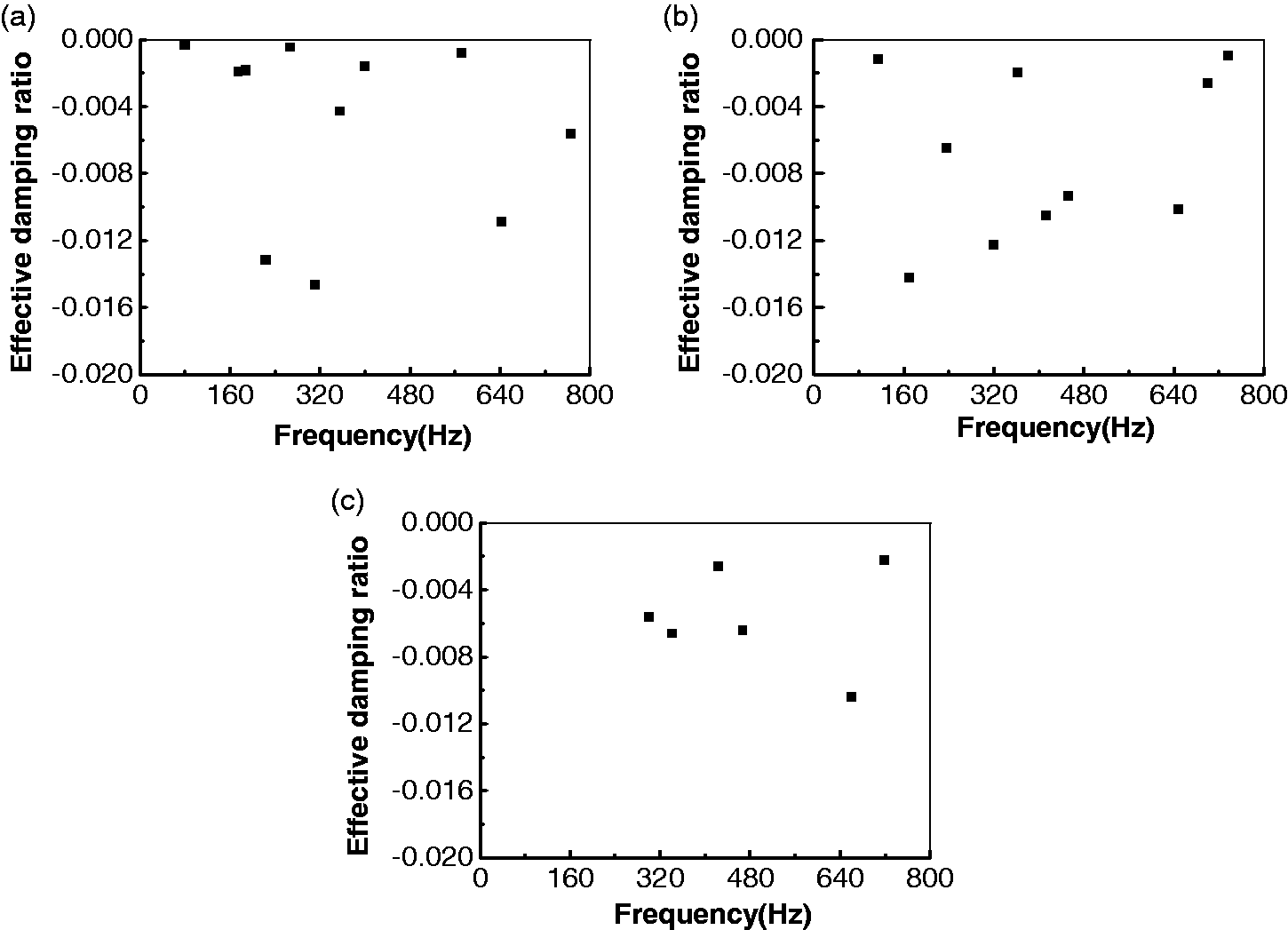
Effect of the modulus of elasticity of the rubber rest pad on the self-sustained vibration between the track and the wheelset: (a) E = 10 MPa; (b) E = 20 MPa; (c) E = 50 MPa.
Effect of the damping coefficient of the rubber rest pad
Damping has a high impact on the self-sustained vibration between the track and the wheelset. It is commonly believed that the greater the damping, the stronger the vibration suppression to the unstable vibration. In this section, the effect of the damping coefficient of the rubber rest pad on rail corrugation is studied. The Rayleigh damping model is applied to consider the material damping of the rubber rest pad, in which the damping matrix is expressed as follows
31

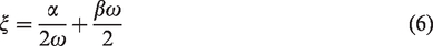

In this paper, it is assumed that the damping matrix is directly proportional to the stiffness matrix, i.e. α = 0. The damping ratios of different rubber materials are generally 0.02–0.3. The frequency range of this study is 20–800 Hz, according to (7), β = 7.79e−6–1.16e−4. In order to study the influence of the damping coefficient on the rail corrugation, the self-sustained vibrations of the system are studied when the damping coefficient β changes in the range of 0–0.0001.
Figure 9 shows the effect of the damping coefficient on the unstable vibration between the track and the wheelset. From Figure 9, it can be seen that the frequency of the most likely unstable vibration moves to the high-frequency zone with the increase of the damping coefficient, which indicates that the bigger the damping coefficient, the shorter the wavelength of the corrugation wear. From Figure 9(a) to (e), it can be seen that with the increase of the damping coefficient, the number of the unstable vibration and the absolute value of the effective damping ratio decrease significantly. When the damping coefficient increases from 1e-5 to 5e-5, the number of unstable vibration of the system is reduced from 8 to 4. When the damping coefficient further increases to 1e-4, the unstable vibration of the wheel–track system completely disappears, which indicates that the rail corrugation will be suppressed to the greatest extent. From the above results, it can be concluded that increasing the damping coefficient of the rubber rest pad can effectively suppress the rail corrugation. Bringing the damping coefficient of the rubber rest pad above 0.0001 can significantly alleviate the rail corrugation.
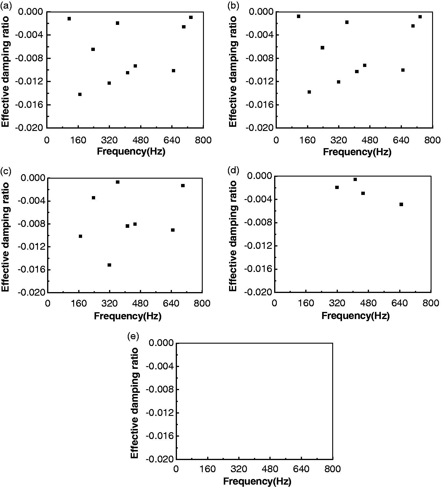
Effect of the damping coefficient of the rubber rest pad on the self-sustained vibration between the track and the wheelset: (a) β = 0.0; (b) β = 1e−6; (c) β = 1e−5; (d) β = 5e−5; (e) β = 1e−4.
Effect of the stiffness and damping of the rubber vibration damper pad under the track slab
A rubber pad floating slab track structure is adopted in the subway line studied in this paper. The rubber vibration damper pad is laid under the track slab, and supported at the whole bottom of the track slab. In this paper, the rubber vibration damper pad is simplified as s series of springs and dampers distributed uniformly under the track slab, whose stiffness and damping are calculated by the following formula
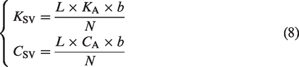
Figure 10 shows the effect of the stiffness of the rubber pad on the corrugation wear. From Figure 10(a) to (e), we can see that the frequency distribution of the self-sustained vibration between the track and the wheelset and the effective damping ratio are almost unchanged when the stiffness of the rubber damping pad varies in the range of 200–1200 N/mm, which indicates that the influence of the stiffness of the rubber pad on the rail corrugation can be ignored. The same conclusion can also be derived from Figure 11. From the above analysis, we can conclude that the stiffness and damping of the rubber vibration damper pad has little influence on the rail corrugation.
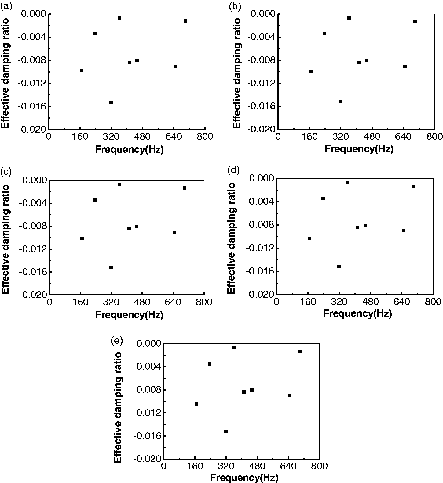
Effect of the stiffness of the rubber pad under the floating slab track bed on the self-sustained vibration between the track and the wheelset: (a) KSV = 200 N/mm; (b) KSV = 400 N/mm; (c) KSV = 600 N/mm; (d) KSV = 800 N/mm; (e) KSV = 1200 N/mm.
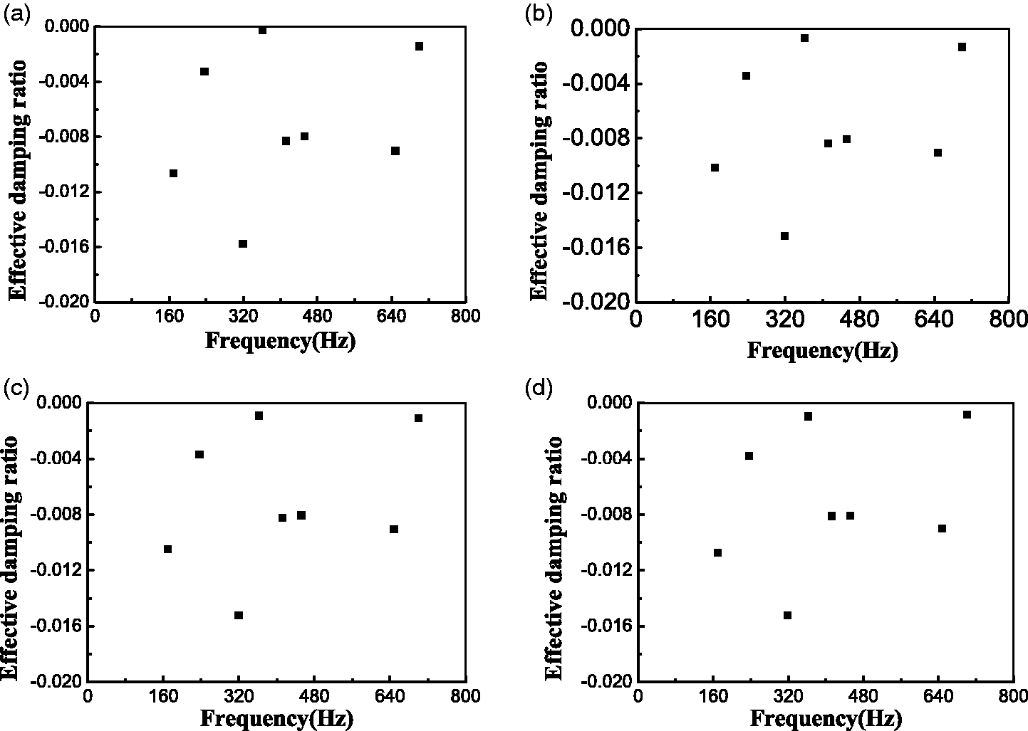
Effect of the damping of the rubber pad under the floating slab track bed on the self-sustained vibration between the track and the wheelset: (a) CSV = 60 N·s/mm; (b) CSV = 150 N·s/mm; (c) CSV = 300 N·s/mm; (d) CSV = 350 N·s/mm.
Conclusions
This paper conducts a numerical study on the origin of the corrugation wear occurring on the rails mounted with Vanguard fasteners. The complex modal analysis is applied to analyze the dynamic stability of the wheelset–track system. Some countermeasures are proposed based on the parameter sensitivity analysis. The conclusions are given as follows:
When the vehicle negotiates this small radius track with Vanguard fasteners, the friction-sustained vibration caused by the saturated wheel–rail creep force is responsible for the severe corrugation on the inner rail. The wavelength of the rail corrugation is 51 mm, and the frequency of the corrugation is 319 Hz, which is consistent with the field measurement data. The modulus of elasticity and the damping coefficient of the rubber rest pad have an important influence on the rail corrugation. The greater the elastic modulus and the damping coefficient, the lower the possibility of the oppearance of the rail corrugation, and the shorter the wavelength of the rail corrugation. Increasing the modulus of elasticity are beneficial to suppression of the rail corrugation occuring in the track installed with Vanguard fasteners. Bringing the damping coefficient of the rubber rest pad above 0.0001 can completely eliminate the rail corrugation. The effect of the stiffness and damping of the rubber pad under the floating slab track bed is negligible.
Footnotes
Declaration of conflicting interests
The author(s) declared no potential conflicts of interest with respect to the research, authorship, and/or publication of this article.
Funding
The author(s) disclosed receipt of the following financial support for the research, authorship, and/or publication of this article: This study was supported by the National Natural Science Foundation of China (No. 51775461).