
Abstract
Planter gear system is one of the critical components of various industrial transmission systems. In general, the ring gear is elastically fixed with the gearbox. The gearbox materials and their assembly relationships will affect the support stiffness of the ring gear and system vibrations. In this paper, a multi-body dynamic model for a planetary gear system with the elastic support of ring gear is developed to discuss the influence of the radial support stiffness of ring gear on the system vibrations. The planet bearings are also considered in the multi-body dynamic model. The rotational speed of the planet gear and carrier from the simulation and theoretical results are compared to validate the developed multi-body dynamic model. The influences of the radial support stiffness of the ring gear, carrier moment, and sun gear speed on the time- and frequency-domain vibrations of the planetary gear system are analyzed. The results denote that the waveform and amplitude of the time-domain vibration of the ring gear are greatly affected by the radial support stiffness of ring gear as well as the peak frequency amplitude and its sidebands. The peak frequency in the spectrum of ring gear is slightly affected by the radial support stiffness. It indicates that this study can give some guidance for the vibration control approaches for the planetary gear systems.
Introduction
Planetary gear system is one of the critical components of various industrial transmission systems, such as aero-engines and wind turbine gearboxes. The dynamic performances of the planetary gear system have a large influence on vibrations of the transmission systems. Moreover, the manufacturing errors and faults in the planetary gear system will greatly affect the vibrations of the transmission systems.1–3 Thus, vibration analysis of the planetary gear system is very helpful for understanding the vibrations and noise of the transmission systems.
Many works have developed various methods including the lumped parameter modeling, finite element (FE) modeling, multibody dynamic (MBD) modeling, and experimental methods for studying the vibrations of planetary gear systems.4,5 For example, Ambarisha and Parker 6 and Kahraman et al. 7 introduced lumped-parameter and FE models to study the vibrations of a planetary gear system. Lethé et al., 8 Halsen et al., 9 Xing and Moan, 10 Helsen et al., 11 Jin et al., 12 and Li et al. 13 established different MBD models to analyze the vibrations of the planetary gearbox system. Guo and Parker 14 presented a nonlinear dynamic model considering the bearing clearance and tooth backlash to discuss the nonlinear vibrations. Guo and Parker 15 developed a lumped-parameter model considering bearing clearances, back-side contact, tooth separation, and tooth wedging to analyze the translational vibrations of planetary gear system. Kim et al. 16 studied the influences of the bearing deformations on the time-varying contact ratios and pressure angles of the planetary gear system as well as the vibrations. Chen et al.17,18 proposed a new method to study the effect of ring gear flexibility on the dynamic performance of planetary gear transmission set with a thin ring gear rim. Although various analytical, FE, and MBD methods have been utilized to describe the vibrations of planetary gear system, the influence of the support stiffness of ring gear on the vibrations of planetary gear system was not discussed in the above literature. However, in practice, the support stiffness of ring gear has a great influence on the system vibrations. 19 On the other hand, Wu and Parker 19 and Liu et al. 20 studied the support stiffness of the ring gear on its vibrations. They only formulated the single ring gear models. The dynamic model for the planetary gear system considering both the support stiffness of the ring gear and planet bearings was not reported in the literature. Thus, the support stiffness of ring gear should be modeled for vibration analysis of the planetary gear systems, which is the goal of this paper.
In this paper, an MBD model for a planetary gear system with the elastic support of the ring gear is developed to discuss the influence of the radial support stiffness of the ring gear on the system vibrations. The planet bearings with the radial clearance are also considered in the MBD model. The meshing stiffness and damping for the meshing gears and bearing components are considered in the MBD model. A Coulomb friction model is utilized to model the frictions between the mating components of the system. A commercial MBD analysis software is applied to solve the developed MBD model. The rotational speed of the planet gear and carrier from the simulation and theoretical results are compared to validate the developed MBD model. The influences of the radial support stiffness of the ring gear, carrier moment, and sun gear speed on the time- and frequency-domain vibrations of the planetary gear system are analyzed.
Problem description
A planetary gear system with the elastic support of the ring gear and planet bearings is plotted in Figure 1. In general, the ring gear is elastically fixed with the gearbox. The gearbox materials and the assembly relationship will affect the radial support stiffness of the ring gear. As the results in Wu and Parker, 19 the dynamics of the ring gear can be greatly influenced by the radial support stiffness of the ring gear. The dynamics of the ring gear will affect the system vibrations.
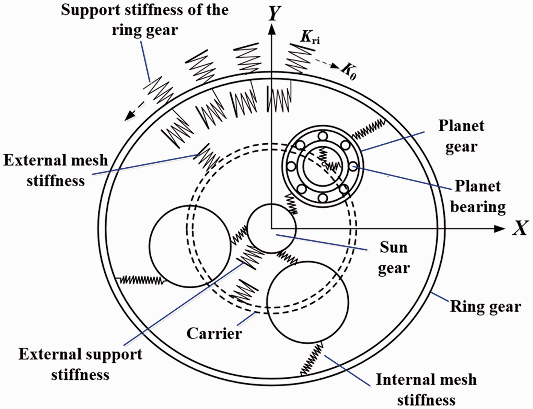
Schematics of a planetary gear system.
To analyze the influence of the radial support stiffness of the ring gear on the vibrations of the system, a radial stiffness ratio is defined as
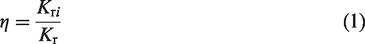
Radial stiffness ratios in the simulation cases.
Model formulation
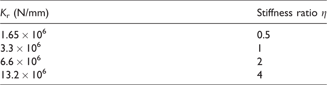
The dynamic model for a planetary gear system is depicted in Figure 2. The model includes three planet gears, three planet bearings, one carrier, one ring gear, and one sun gear. The input speed and the moment are applied on the sun gear and carrier, respectively. The contacts between the gears and those in the planet bearings are modeled too. The mesh stiffnesses between the gears from equations (2) and (3) are considered in the MBD model as well as the contact stiffness between the planet-bearing components. The planet gears, planet bearings, carrier, ring gear, and sun gear are considered as rigid bodies. The discrete radial support stiffness and circumferential torsion stiffness of the ring gears are considered in the MBD model as shown in Figure 2.
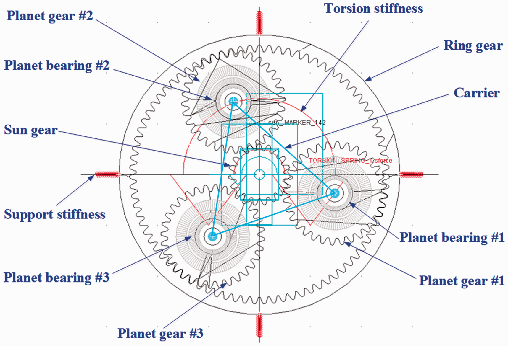
A dynamic model for a planetary gear system.
Based on the potential energy principle, the total equivalent mesh stiffness between the sun and planet gear is calculated by21–23


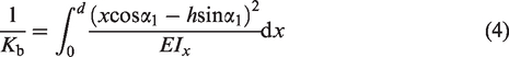
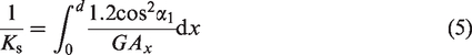
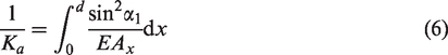
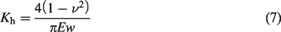
The Hertzian contact stiffness Kh is
The contact stiffness between the ball and races is as follows29,30

Moreover, the governing equation of the MBD model is defined as

Results and discussion
The simulation cases are given in Table 2, where nin is the input speed of the sun gear and Mp is the moment of the carrier. The dynamic model in “Model formulation” section is solved in a commercial MBD analysis software MSC. ADAMS. The influence of the radial support stiffness of the ring gear is given in the following sections. Tables 3 and 4 give the geometrics for the planetary gear system and planet bearing, respectively. According to the parameters, the meshing stiffness and damping between sun and planet gears are 4.71 × 10⁵ N/mm and 86.62 N s/mm, respectively, and those between the planet and ring gears are 9.28 × 10⁵ N/mm and 157.59 N s/mm, respectively. The contact stiffness and damping between the ball and inner race are 2.49 × 10⁷ N/mm and 6228 N s/mm, respectively, and those between the ball and outer race are 1.94 × 10⁷ N/mm and 4858 N s/mm, respectively. The time-varying mesh stiffness is calculated in equations (2) and (3). In this paragraph, only the maximum meshing stiffness of the single tooth meshing case is given. The meshing stiffness for the multi-tooth meshing cases is determined by the contact relationships between the teeth of gears in the MBD model. This method means that a rectangular profile of total meshing stiffness between the gears is used in the MBD model.
Input speed and applied moment used in the simulation cases.
Geometrics for the planetary gear system.
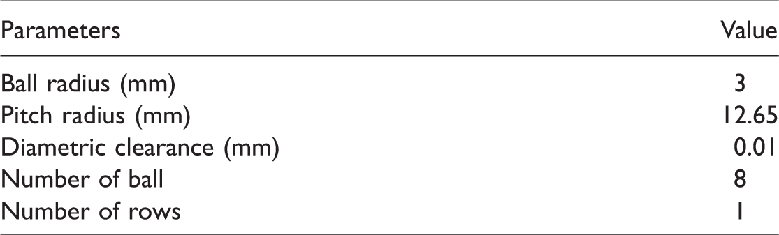
Geometrics for the planet bearing.
Peak frequencies and their amplitudes for case 1.
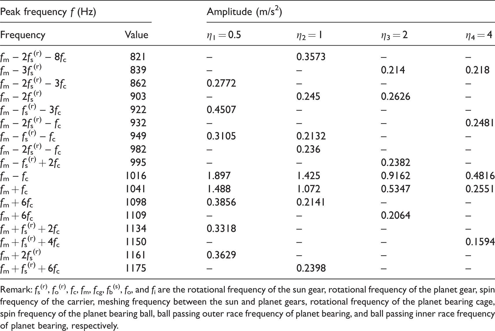
Remark: fs(r), fo(r), fc, fm, fcg, fb(s), fo, and fi are the rotational frequency of the sun gear, rotational frequency of the planet gear, spin frequency of the carrier, meshing frequency between the sun and planet gears, rotational frequency of the planet bearing cage, spin frequency of the planet bearing ball, ball passing outer race frequency of planet bearing, and ball passing inner race frequency of planet bearing, respectively.
Model validation
To validate the developed model, the rotational speed of the planet gear and carrier from the simulation and theoretical results are compared. Here, the input speed of the sun gear is 387 r/min, and the moment applied on the carrier is 350 Nm. Figure 3 gives the simulation rotational speed of the planet gear #1 and carrier. In Figure 3, the simulation mean values for the planet gear # 1 and carrier are 1779.84 and 1116.28 r/min, respectively. According to the theortical method in Lei et al., 33 their theoretical values are 1779.84 and 1116.28 r/min, respectivley. The above discussions may show some valiation for the developed modeling approach. Note that the fluctuation of the calculation speed of the component can be observed. The fluctuation maybe caused by some clearances or gaps between the gear pairs or in the rolling bearings. Although the fluctuation occurs in the calculation speed, the mean value of the calculation speed is a constant value as shown in Figure 3. Thus, the mean value of the calculation speed from the simulation results is compared with the theoretical results.
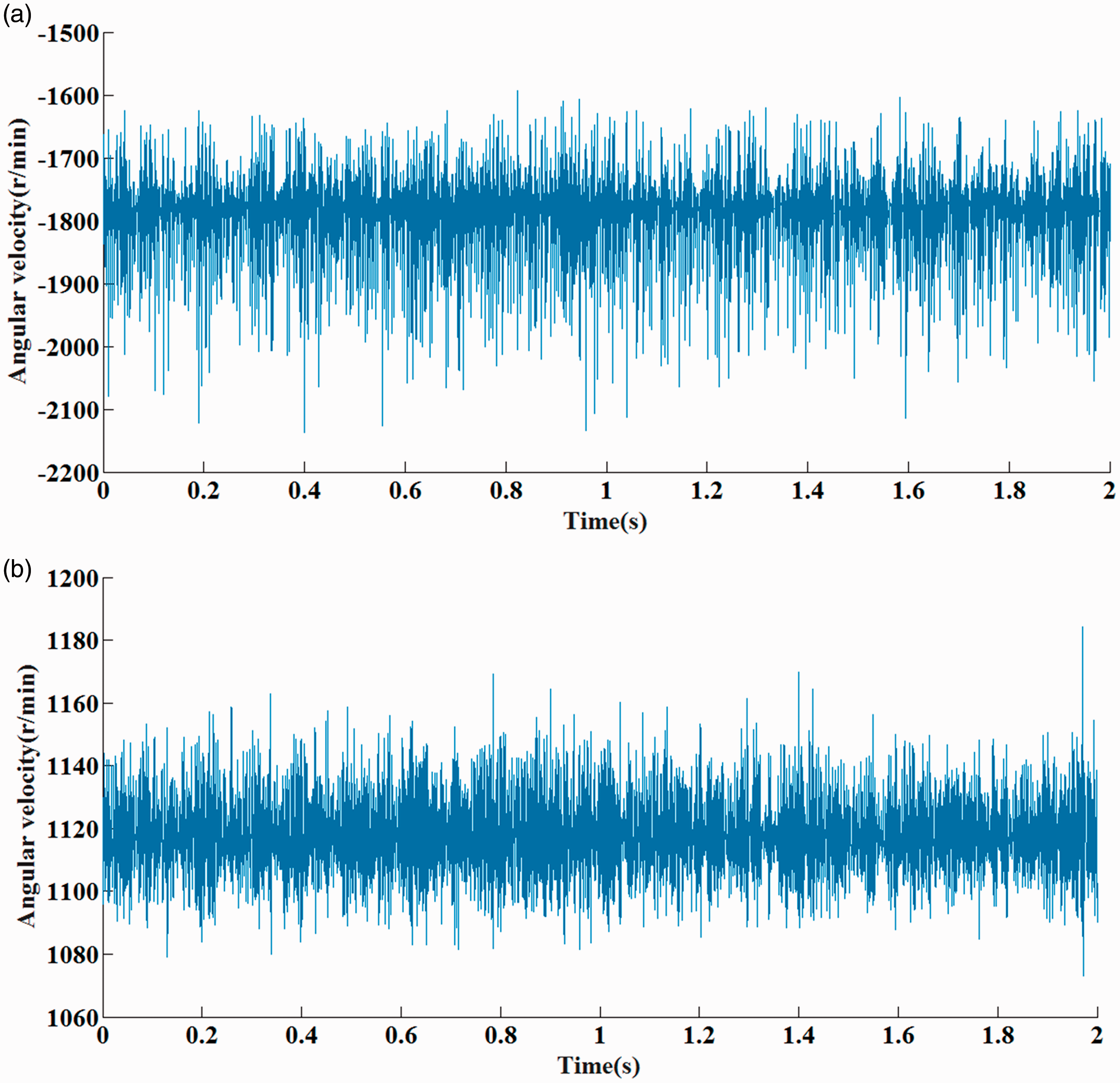
The simulation rotational speed of (a) planet gear #1 and (b) carrier.
The influence of the radial support stiffness on the vibrations
Time-domain vibrations
Figure 4 gives the influences of the stiffness ratios on the time-domain accelerations of the ring gear under the simulation case 1 (nin = 4000 r/min and Mp = 50 Nm). It depicts that the radial support stiffness has a large influence on the profile and amplitude of the acceleration for the ring gear. The maximum amplitude will decrease with the radial support stiffness. In Figure 4, the maximum acceleration amplitudes of the ring gear with different stiffness ratios are 68.08, 57.54, 48.67, and 40.68 m/s2, respectively.
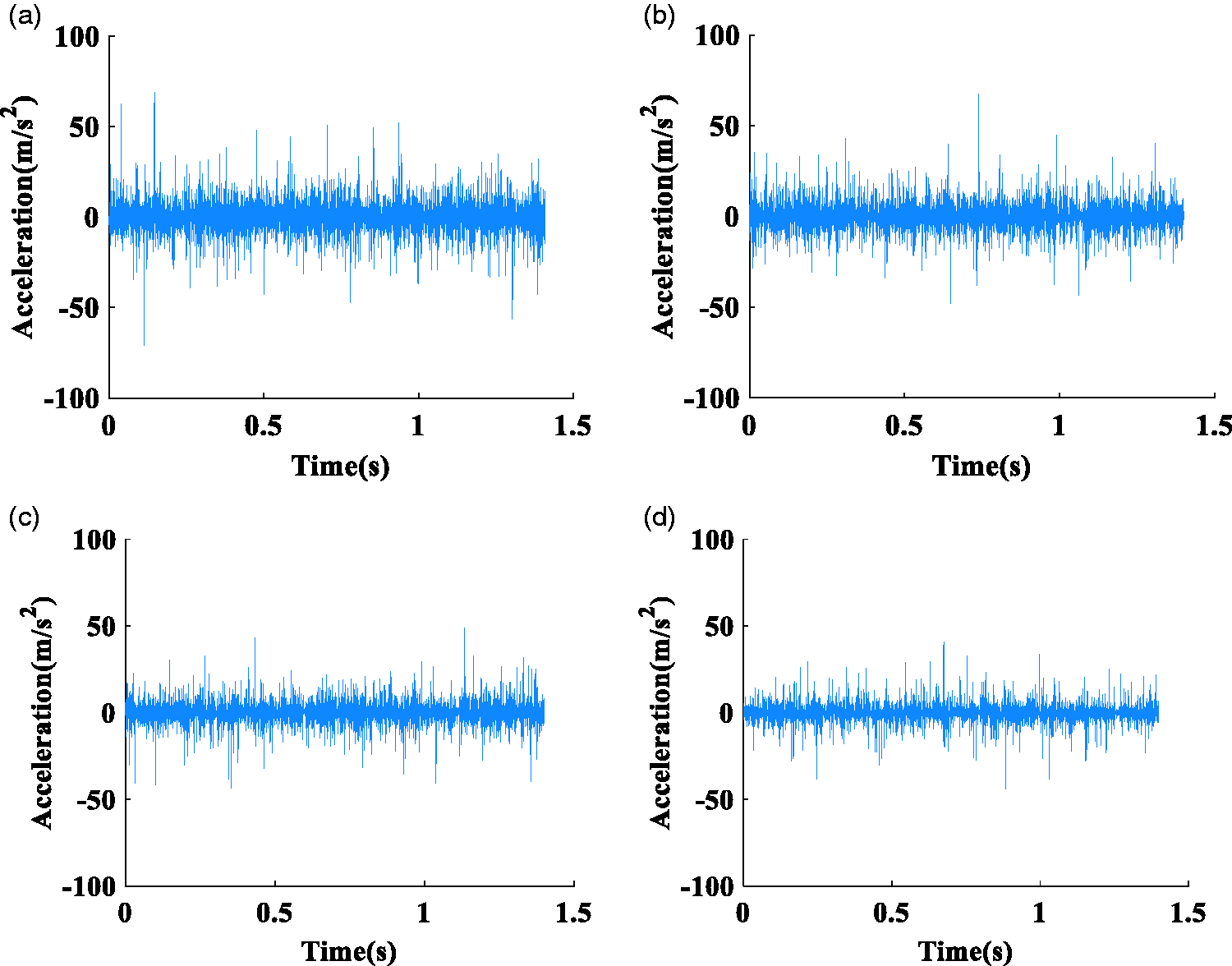
Time-domain accelerations of the ring gear for simulation case 1: (a) η1 = 0.5, (b) η2 = 1, (c) η3 = 2, and (d) η4 = 4.
To evaluate the radial support stiffness of the ring gear on the time-domain vibration, three statistical parameters, such as maximum, peak to peak (PTP), and root mean square (RMS) values, are utilized. Figure 5 introduces the influence of the radial support stiffness on the RMS, maximum, and PTP values of the accelerations of the ring gear for different moments. As shown in Figure 5, the input speed is 6000 r/min. Figure 6 describes the influence of the radial support stiffness on the RMS, maximum, and PTP values of the vibrations of the ring gear for different input speeds. As shown in Figure 6, the moment is 50 Nm. As plotted in Figures 5 and 6, the maximum, PTP, and RMS values always decrease with the increase of the stiffness ratio; they always increase with the increase with the carrier moment when the input speed of the sun gear is fixed; and they always increase with the increase with the input speed of the sun gear when the carrier moment is a constant.
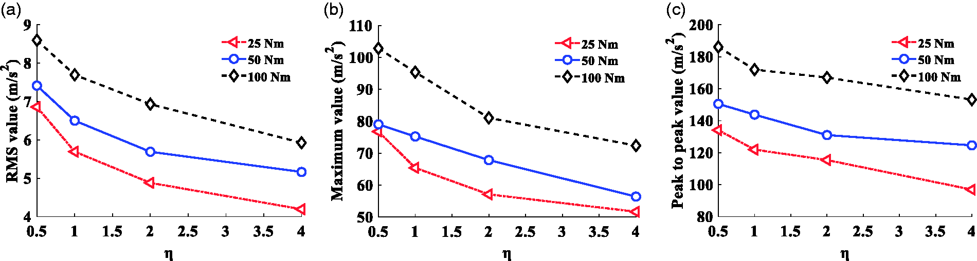
The influence of the radial support stiffness on the (a) RMS, (b) maximum, and (c) PTP values of the accelerations of the ring gear for different moments.
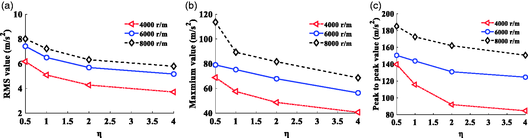
The influence of the radial support stiffness on the (a) RMS, (b) maximum, and (c) PTP values of the accelerations of the ring gear for different input speeds.
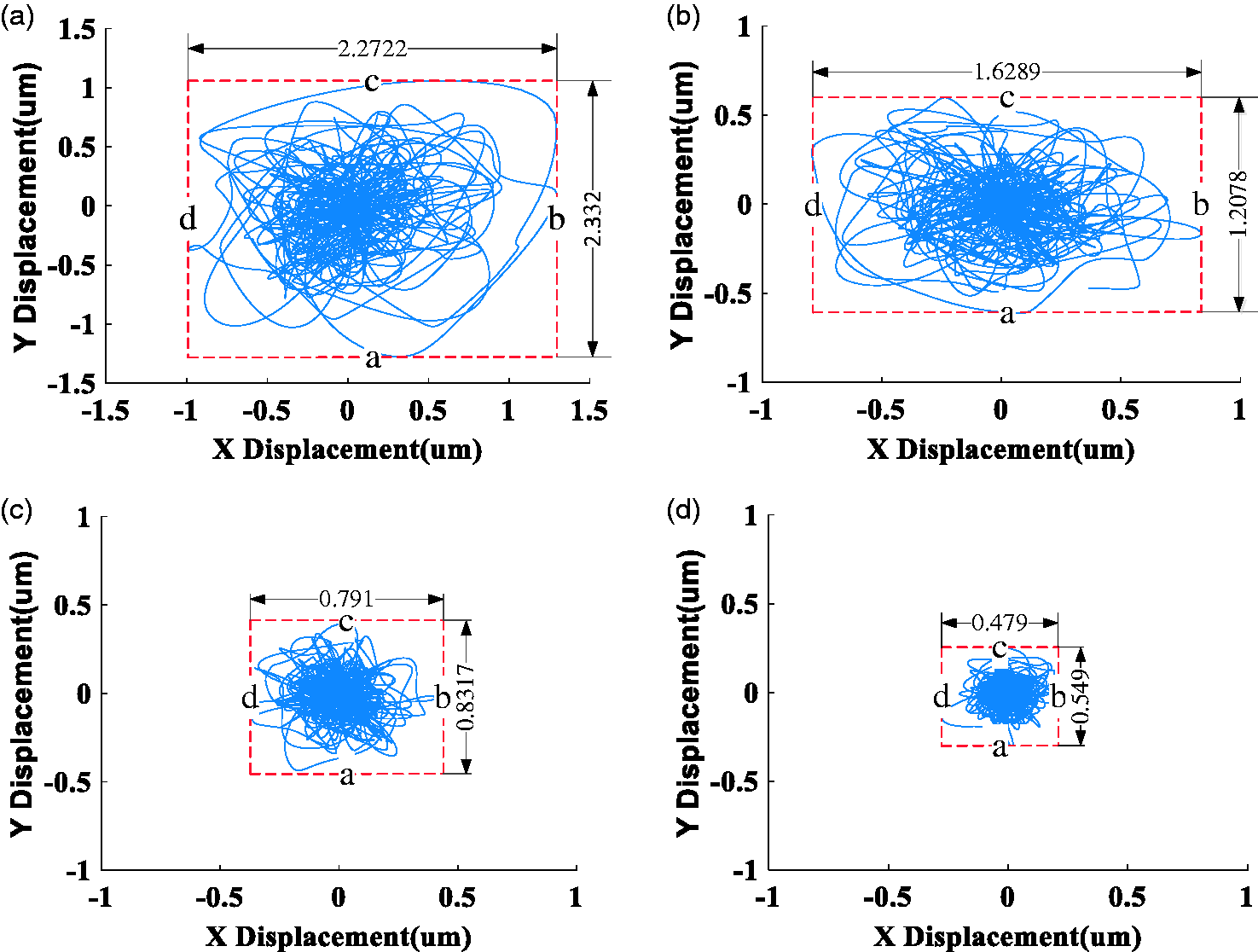
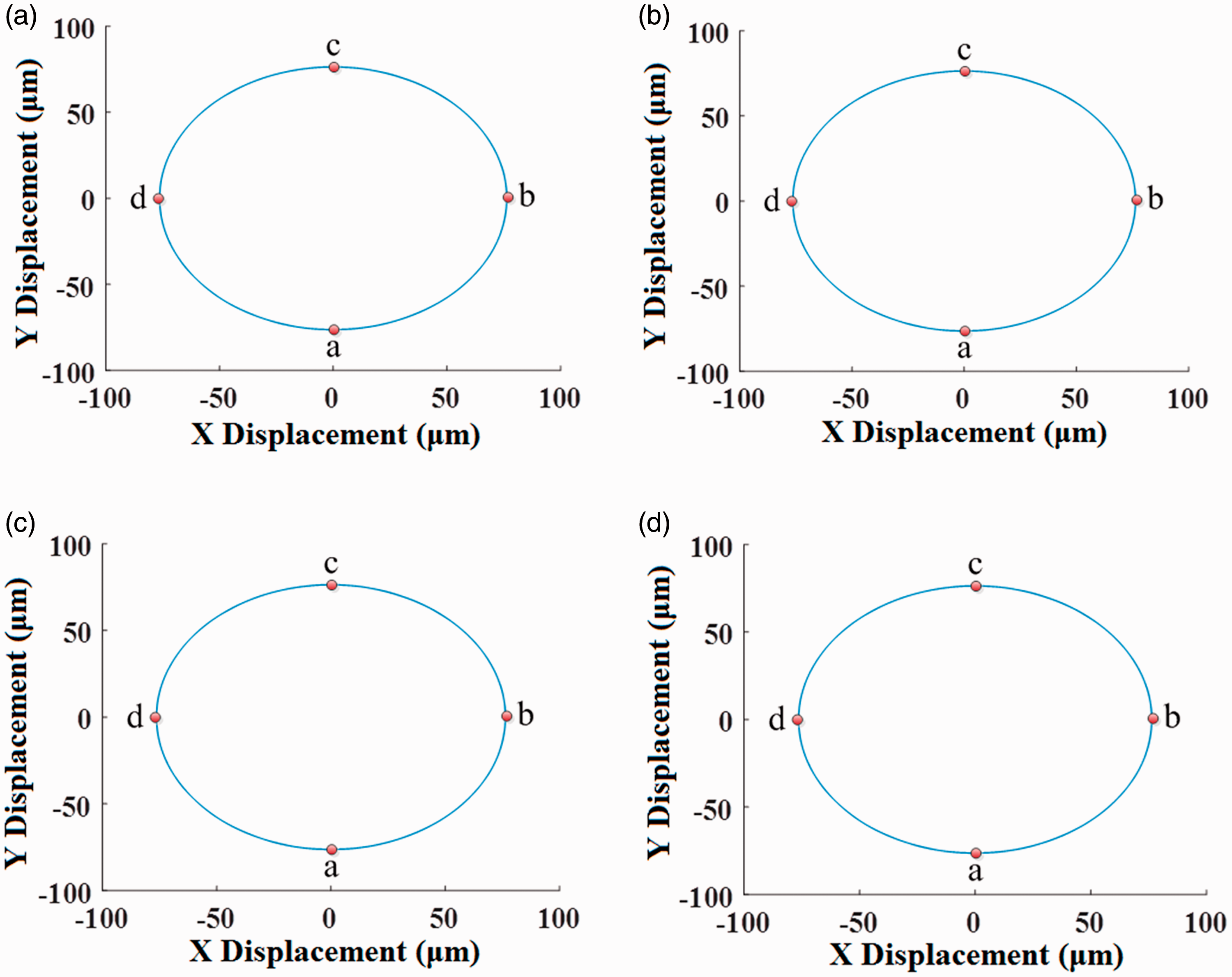
Furthermore, the influence of the radial support stiffness on the orbit plots of the ring gear and planet gear #1 is given in Figures 7 and 8, respectively. Since the orbit plot profiles of three planet gears are similar, only the orbit plot for planet gear #1 is shown. The orbit ranges of three planet gears are still analyzed. The orbit ranges of the system bodies are described by four range parameters a, b, c, and d. The influence of the radial support stiffness on the above four range parameters is plotted in Figure 9. It gives that the orbits of ring and planet gears are greatly influenced by the radial support stiffness, especially for that of ring gear. The orbit ranges of ring and planet gears decrease with the radial support stiffness as shown in Figure 9. The orbits for three planet gears are different, which may be produced by the clearances or elastic ring foundations, etc. As shown in Figure 9(b) to (d), although the behaviors of planet gear #1 are different from those of planet gear #2 and #3 when η is increasing, their differences are very small; the reason may be that the meshing positions of the three planet gears are different due to the vibrations caused by the clearances of the planet bearings, clearances between the gears, and the elastic support of ring gear, etc.
The influence of the radial support stiffness on the orbit plots of the ring gear for (a) η = 0.5, (b) η = 1, (c) η = 2, and (d) η = 4.
The influence of the radial support stiffness on the orbit plots of the planet gear #1 for (a) η = 0.5, (b) η = 1, (c) η = 2, and (d) η = 4.
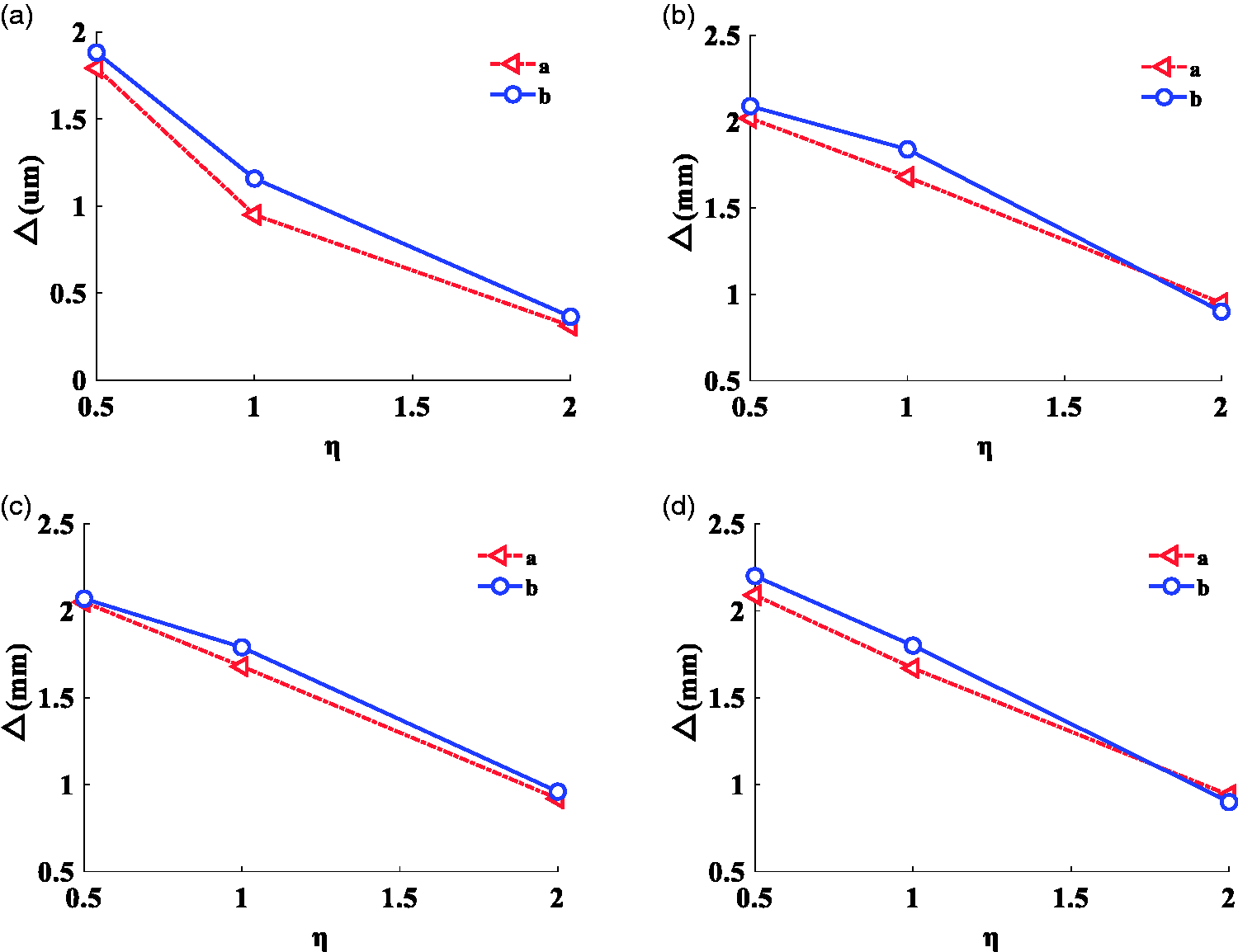
The influence of the radial support stiffness on the orbit ranges of (a) ring gear, (b) planet gear #1, (c) planet gear #2, and (d) planet gear #3.
Frequency-domain vibrations
Figure 10 gives the influence of the radial support stiffness on the frequency-domain vibrations of the ring gear for simulation case 1 (nin = 4000 r/min and Mp = 50 Nm). In Figure 10(a), for η1 = 0.5, a peak frequency fm – fc = 1016 Hz is observed, and there are some sidebands around the peak frequency, which include fm – 2fs(r) – 3fc = 862 Hz, fm – fs(r) – 3fc = 922 Hz, fm – fs(r) – fc = 949 Hz, fm + fc = 1041 Hz, fm + 6fc = 1098 Hz, fm + fs(r) + 2fc = 1134 Hz, and fm + 2fs(r) = 1161 Hz. In Figure 10(b), for η2 = 1, a peak frequency fm – fc = 1016 Hz is also observed, and the sidebands are fm – 2fs(r) – 8fc = 821 Hz, fm – 2fs(r) = 903 Hz, fm – fs(r) – fc = 949 Hz, fm + fc = 1041 Hz, fm + 6fc = 1098 Hz, and fm + fs(r) + 6fc = 1175 Hz. In Figure 10(c), for η3 = 2, a peak frequency fm – fc = 1016 Hz is observed too, and the sidebands include fm – 3fs(r) = 839 Hz, fm – 2fs(r) = 903 Hz, fm – fs(r) + 2fc = 995 Hz, fm + fc = 1041 Hz, and fm + 6fc = 1109 Hz. In Figure 10(d), for η4 = 4, a peak frequency fm – fc = 101 Hz is also observed, and the sidebands are fm – 3fs(r) = 842 Hz, fm – 2fs(r) – fc = 932 Hz, fm – fs(r) – 3fc = 932 Hz, fm + fc = 1041 Hz, and fm + fs(r) + 4fc = 1150 Hz. Table 5 gives comparisons of the peak frequency, sidebands, and their amplitudes for different stiffness ratio cases. Although the four stiffness ratio cases have a same peak frequency, as given in Table 5, their amplitudes are very different. The amplitudes for the above four cases are 1.897, 1.425, 0.9162, and 0.4861 m/s2, respectively. It denotes that the peak frequency amplitude decreases with the radial support stiffness.
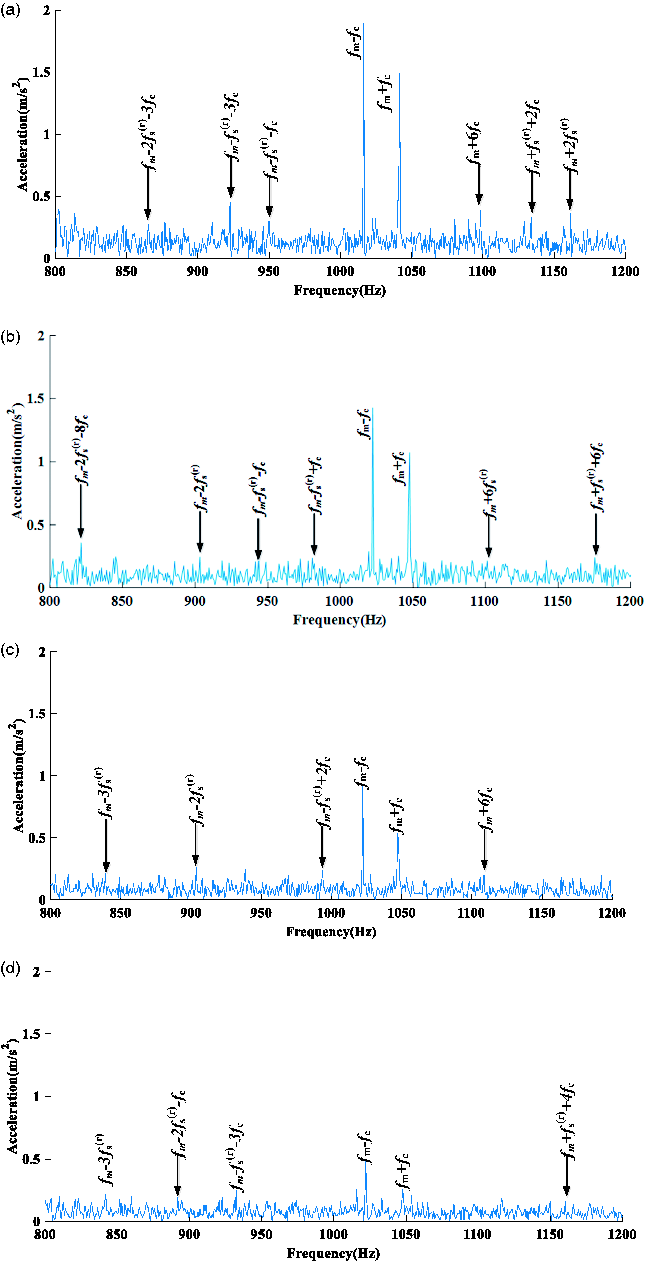
Frequency-domain accelerations of the ring gear for simulation case 1: (a) η1 = 0.5, (b) η2 = 1, (c) η3 = 2, and (d) η4 = 4.
Since the spectrum waveforms for different simulation cases are similar and their differences are the peak frequencies, the spectrum waveforms for the simulation cases 2, 3, 4, and 5 are not shown as follows. However, their peak frequencies, sidebands, and relative amplitudes will be discussed in the next paragraphs.
Table 6 plots the influence of the radial support stiffness on the frequency-domain vibrations of the ring gear for simulation case 2 (nin = 6000 r/min and Mp = 50 Nm). For η1 = 0.5, a peak frequency fm – fc = 1532 Hz is observed, and the sidebands include fm – fs(r) – 2fc = 1405 Hz, fm + fc = 1569 Hz, fm + fs(r) = 1641 Hz, and fm + fs(r) + 3fc = 1701 Hz. For η2 = 1, a peak frequency fm – fc = 1532 Hz is also observed, and the sidebands are fm – fs(r) – fc = 1426 Hz, fm + fc = 1569 Hz, fm + fs(r) = 1641 Hz, and fm + fs(r) + 3fc = 1701 Hz. For η3 = 2, a peak frequency fm – fc = 1532 Hz is observed too, and the sidebands include fm – fs(r) – 2fc = 1405 Hz, fm – 3fc = 1491 Hz, fm + fc = 1569 Hz, fm + fs(r) = 1641 Hz, and fm + fs(r) + 3fc = 1701 Hz. For η4 = 4, a peak frequency fm + fc = 1569 Hz is also observed, and the sidebands are fm – fs(r) – 2fc = 1405 Hz, fm – 3fc = 1491 Hz, fm – fc = 1532 Hz, fm + fs(r) = 1641 Hz, and fm + fs(r) + 3fc = 1701 Hz. Table 6 shows that the peak frequencies of the first three stiffness ratio cases are at fm – fc, but that of the fourth stiffness ratio case is at fm + fc. Although the first three stiffness ratio cases have a same peak frequency, as given in Table 6, their amplitudes are very different. The peak frequency amplitudes for the above first three cases are 2.209, 1.166, and 1.281 m/s2, respectively, and that for the fourth case is 0.5774 m/s2. Similarly, it shows that the peak frequency amplitude decreases with the radial support stiffness.
Peak frequencies and their amplitudes for case 2.
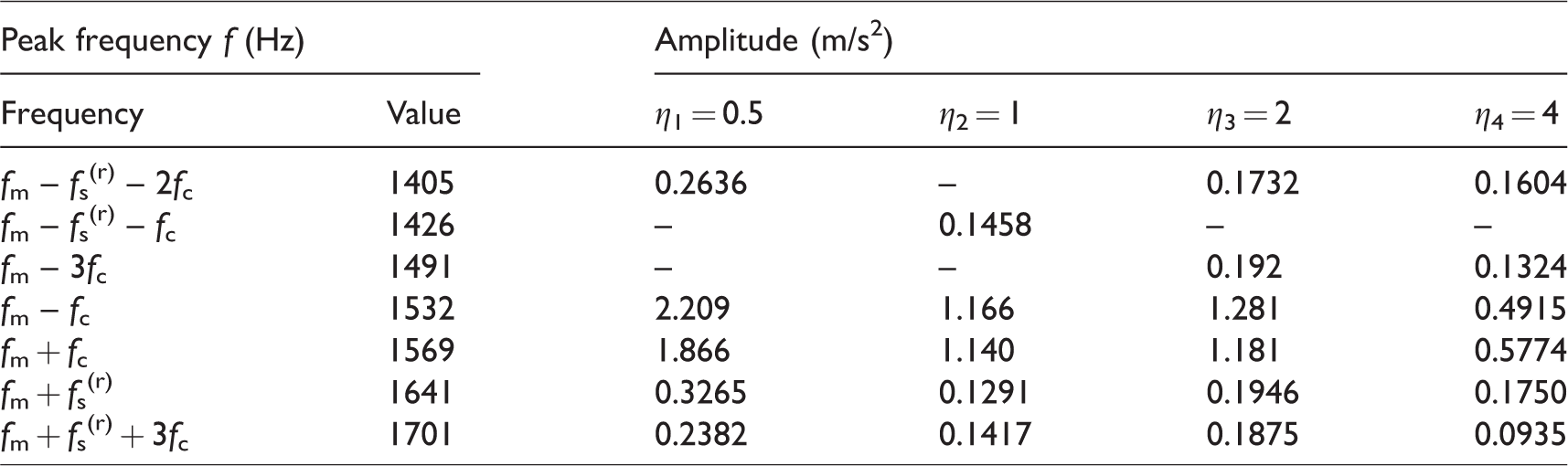
Table 7 plots the influence of the radial support stiffness on the frequency-domain vibrations of the ring gear for simulation case 3 (nin = 8000 r/min and Mp = 50 Nm). For η1 = 0.5, a peak frequency fm – fc = 2041 Hz is observed, and the sidebands are fm – 3fs(r) – 4fc = 1565 Hz, fm – 3fs(r) = 1669 Hz, fm – 3fc = 1963 Hz, fm + fc = 2090 Hz, fm + fs(r) + 4fc = 2299 Hz, and fm + fs(r) + 8fc = 2392 Hz. For η2 = 1, a peak frequency fm – fc = 2041 Hz is also observed, and the sidebands include fm – 3fs(r) – 4fc = 1565 Hz, fm – 3fs(r) = 1669 Hz, fm – fs(r) – 5fc = 1778 Hz, fm – fs(r) = 1932 Hz, fm + fc = 2090 Hz, fm + fs(r) + 4fc = 2299 Hz, and fm + fs(r) + 8fc = 2392 Hz. For η3 = 2, a peak frequency fm – fc = 2041 Hz is observed too, and the sidebands are fm – 3fs(r) – 4fc = 1565 Hz, fm – 3fs(r) = 1669 Hz, fm – fs(r) – 5fc = 1778 Hz, fm – fs(r) = 1932 Hz, fm + fc = 2090 Hz, and fm + fs(r) + 8fc = 2392 Hz. For η4 = 4, a peak frequency fm – fc = 2041 Hz is also observed, and the sidebands include fm – 3fs(r) – 4fc = 1565 Hz, fm – 3fs(r) = 1669 Hz, fm – fs(r) = 1932 Hz, fm + fc = 2090 Hz, fm + fs(r) + 4fc = 2299 Hz, and fm + fs(r) + 8fc = 2392 Hz. Although the four stiffness ratio cases have a same peak frequency, as given in Table 7, their amplitudes are very different. The peak frequency amplitudes for the above four cases are 1.597, 1.795, 1.181, and 0.8976 m/s2, respectively. Similarly, it shows that the peak frequency amplitude decreases with the radial support stiffness.
Peak frequencies and their amplitudes for case 3.
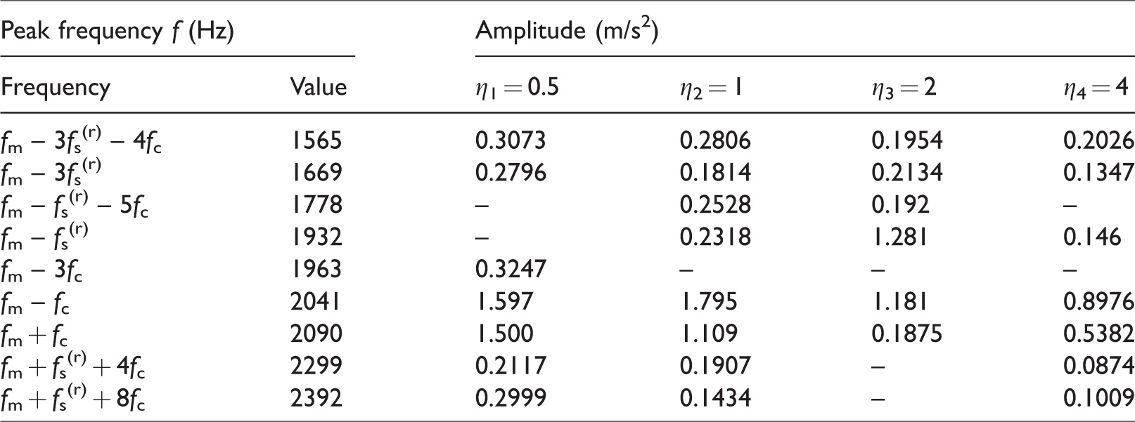
Table 8 plots the influence of the radial support stiffness on the frequency-domain vibrations of the ring gear for simulation case 4 (nin = 6000 r/min and Mp = 25 Nm). For η1 = 0.5, a peak frequency fm – fc = 1532 Hz is observed, and the sidebands include fm – 2fs(r) – 2fc = 1311 Hz, fm – fs(r) – 2fc = 1411 Hz, fm – 4fc = 1445 Hz, fm + fc = 1569 Hz, fm + 4fc = 1656 Hz, and fm + fs(r) + 2fc = 1697 Hz. For η2 = 1, a peak frequency fm – fc = 1532 Hz is also observed, and the sidebands are fm – 2fs(r) – 2fc = 1311 Hz, fm – fs(r) – 2fc = 1411 Hz, fm + fc = 1569 Hz, fm + 4fc = 1656 Hz, and fm + fs(r) + 2fc = 1697 Hz. For η3 = 2, a peak frequency fm – fc = 1532 Hz is observed too, and the sidebands include fm – 2fs(r) – 2fc = 1311 Hz, fm – fs(r) – 2fc = 1411 Hz, fm + fc = 1569 Hz, and fm + fs(r) + 2fc = 1697 Hz. For η4 = 4, a peak frequency fm – fc = 1532 Hz is also observed, and the sidebands are fm – 2fs(r) – 2fc = 1311 Hz, fm – fs(r) – 2fc = 1411 Hz, fm + fc = 1569 Hz, fm + 4fc = 1656 Hz, and fm + fs(r) + 2fc = 1697 Hz. Although the four stiffness ratio cases have a same peak frequency, as given in Table 8, their amplitudes are very different. The peak frequency amplitudes for the above four cases are 1.87, 1.887, 1.408, and 0.6242 m/s2, respectively. Similarly, it shows that the peak frequency amplitude decreases with the radial support stiffness.
Peak frequencies and their amplitudes for case 4.
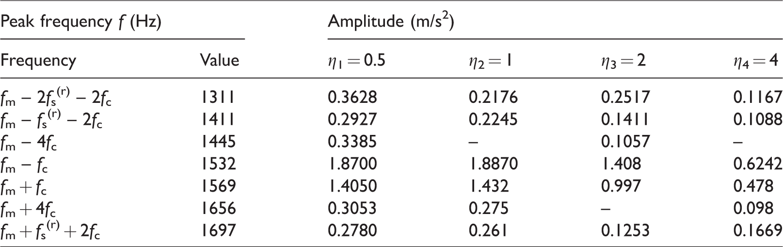
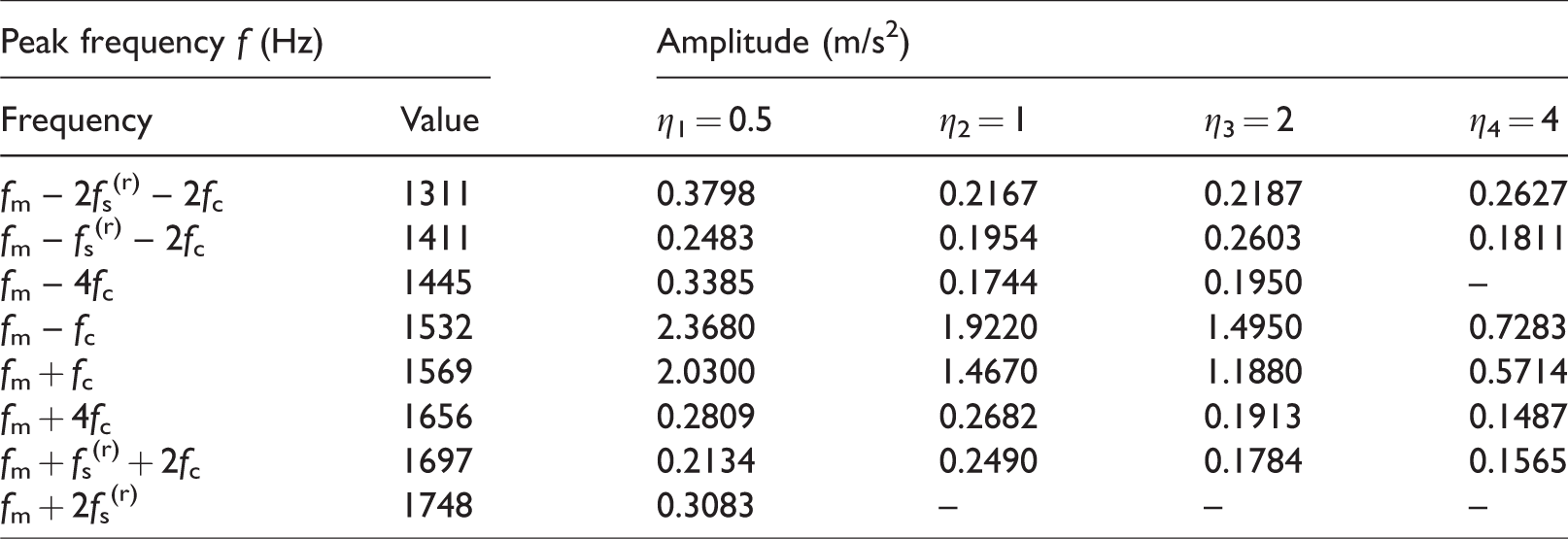
Table 9 plots the influence of the radial support stiffness on the frequency-domain vibrations of the ring gear for simulation case 2 (nin = 6000 r/min and Mp = 100 Nm). For η1 = 0.5, a peak frequency fm – fc = 2041 Hz is observed, and the sidebands are fm – 2fs(r) – 2fc = 1311 Hz, fm – fs(r) – 2fc = 1411 Hz, fm – 4fc = 1445 Hz, fm + fc = 1569 Hz, fm + 4fc = 1656 Hz, fm + fs(r) + 2fc = 1697 Hz, and fm + 2fs(r) = 1748 Hz. For η2 = 1, a peak frequency fm – fc = 2041 Hz is also observed, and the sidebands include fm – 2fs(r) – 2fc = 1311 Hz, fm – fs(r) – 2fc = 1411 Hz, fm – 4fc = 1445 Hz, fm + fc = 1569 Hz, fm + 3fc = 1625 Hz, fm + 4fc = 1656 Hz, and fm + fs(r) + 2fc = 1697 Hz. For η3 = 2, a peak frequency fm – fc = 2041 Hz is observed too, and the sidebands are fm – 2fs(r) – 2fc = 1311 Hz, fm – fs(r) – 2fc = 1411 Hz, fm + fc = 1569 Hz, fm + 3fc = 1625 Hz, fm + 4fc = 1656 Hz, and fm + fs(r) + 2fc = 1697 Hz. For η4 = 4, a peak frequency fm – fc = 2041 Hz is also observed, and the sidebands include fm – 2fs(r) – 2fc = 1311 Hz, fm – fs(r) – 2fc = 1411 Hz, fm + fc = 1569 Hz, fm + 4fc = 1656 Hz, and fm + fs(r) + 2fc = 1697 Hz. Although the four stiffness ratio cases have a same peak frequency, as given in Table 9, their amplitudes are very different. The peak frequency amplitudes for the above four cases are 2.368, 1.922, 1.495, and 0.7283 m/s2, respectively. Similarly, it shows that the peak frequency amplitude decreases with the radial support stiffness.
Peak frequencies and their amplitudes for case 5.
In this section, the sidebands around the peak frequency are clearly observed in the spectrum of the ring gear. The sidebands around the peak frequency include fm – fs(r) – 2fc, fm + fc, fm + fs(r), fm + fs(r) + 3fc, fm – fs(r) – fc, fm + fs(r), fm + fs(r) + 3fc, and fm – 3fc. It shows that the vibrations of planetary gear system are mainly caused by the meshing vibration between sun gear and planet gear, the rotational vibrations of sun gear, and the spin vibrations of carrier. It seems that the passing effects of planet gears will mainly modulate the amplitude of meshing vibration of planetary gears.
Conclusions
This paper develops a MBD model for a planetary gear system with an elastic ring gear support to discuss the influence of the radial support stiffness of the ring gear on the system vibrations. The rotational speed of the planet gear and carrier from the simulation and theoretical results are compared to validate the developed MBD model. The influences of the radial support stiffness of the ring gear, carrier moment, and sun gear speed on the time- and frequency-domain vibrations of the planetary gear system are analyzed. The following conclusions are given as
The waveform and amplitude of the time-domain vibration of the ring gear are greatly affected by the radial support stiffness of the ring gear as well as the peak frequency amplitude and its sidebands. The maximum, PTP, and RMS values always decrease with the increase of the stiffness ratio; they always increase with the increase with the carrier moment when the input speed of the sun gear is fixed, and they always increase with the increase with the input speed of the sun gear when the carrier moment is a constant. The peak frequency (fm – fc) in the spectrum of the ring gear is slightly affected by the radial support stiffness. The peak frequency amplitude decreases with the radial support stiffness. The sidebands around the peak frequency include fm – fs(r) – 2fc, fm + fc, fm + fs(r), fm + fs(r) + 3fc, fm – fs(r) – fc, fm + fs(r), fm + fs(r) + 3fc, and fm – 3fc.
Footnotes
Declaration of conflicting interests
The author(s) declared no potential conflicts of interest with respect to the research, authorship, and/or publication of this article.
Funding
The author(s) disclosed receipt of the following financial support for the research, authorship, and/or publication of this article: The author(s) received financial support from the National Natural Science Foundation of China (No. 51605051), Chongqing Research Program of Basic Research and Frontier Technology (No. cstc2017jcyjAX0202), and Chongqing Special Key R&D Projects for Technology Innovation of Key Industries (No. cstc2017zdcy-zdyfX0101) for the research, authorship, and/or publication of this article.