
Abstract
A speed estimation scheme based on the particle swarm optimization algorithm flux observer is proposed for a sensorless rotor field direct orientation controlled induction motor drive. The stator current and rotor flux was used to establish both the rotor field direct orientation controlled induction motor drive and the rotor-flux observer. The estimated synchronous angle position was acquired from a current-and-voltage parallel-model rotor estimator for implementation of the exact coordinate transformation to achieve a perfect rotor field direct orientation controlled induction motor drive. The rotor-flux observer was designed using the Lyapunov stability theory, and the estimated rotor speed was derived from the developed the rotor-flux estimator; this estimated speed was unaffected by the slip speed. The gain matrix of this flux observer was obtained using the particle swarm optimization algorithm because it is simple, achieves rapid convergence, and is suitable for a variety of conditions. This system was simulated using the MATLAB/Simulink® toolbox, and all the control algorithms were realized by a TI DSP 6713-and-F2812 control card. Both simulation and experimental results confirmed the effectiveness of the proposed approach.
Keywords
Introduction
The development of industry 4.0 demands the use of many high-performance motor drives to actuate tool machines. Induction motors (IMs) are popularly used for this purpose because of their low cost, robustness, small volume, and few maintenance requirements. However, the mathematical model of an IM is nonlinear, coupling, and time-variant, making the control of an IM drive more difficult than the control of a DC motor drive. With application of the field orientation control (FOC) method of an AC motor, the complicated mathematic model of an IM can be transformed into the torque–current component and the field–current component; both components are orthogonal and can be independently controlled. Such a condition is similar to a separately excited DC motor, and the maximum torque-to-current ratio is achieved. 1 According to FOC theory, the FOC IM drives in general are classified as direct or indirect. 2 The direct FOC IM drives utilize the measured motor voltages and currents to estimate the magnitude and position of the flux. The indirect FOC IM drives use the estimated slip angle and rotor position to calculate the flux position. The FOC IM drives are also classified as stator, rotor, and air-gap FOC types. 3 In the stator FOC, the current and flux of the stator are selected as the state variables. In the rotor FOC, the stator current and rotor flux are selected as the state variables. In the air-gap FOC, the stator current and air-gap flux are selected as the state variables. The implementation of a conventional FOC IM drive requires a speed sensor, such as a revolver or an encoder, to detect the rotor position. However, this sensor reduces the drive system robustness and is unsuitable for application of an aggressive environment. Several speed estimation approaches for a sensorless FOC IM drive have been published: utilization of an estimator of flux to develop speed estimation scheme,4–6 adopting an adaptive control system to adjust shaft speed,7–10 a neural network or fuzzy logic approach to determine rotor speed,11–13 and an extended Kalman filter used to determine the estimated speed.14–16 In this study, the speed estimation approach based on the rotor-flux observer is proposed that has advantages over other methods in that control is easy and the number of parameters is lower sensibility. Application of the Lyapunov stability theory to design the rotor-flux observer and using the particle swarm optimization (PSO) algorithm acquires the gain matrix of this observer that has the advantages of simplicity, rapid convergence, and suitability for a variety of conditions. The current-and-voltage parallel-model rotor estimator was developed to obtain the estimated synchronous angle position and guarantee the exact coordinate transformation for implementation of the perfect rotor field direct orientation control (RFDOC) IM drive.
Rotor field direct orientation controlled induction motor drive
The state equations expressed as the stator current and rotor flux of an IM at the synchronous reference coordinate frame are
17

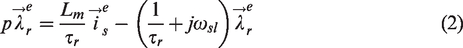
Under an RFDOC condition, setting

Under an RFDOC condition, according to equation (1), the d-axis and q-axis stator current state equations are derived as


Examination of equation (6) reveals that the second and third terms on the right side are the coupling components, and examination of equation (7) reveals that the first and third terms on the right side are also the coupling components. These coupling components allow definition of the d-axis and q-axis stator voltage feed-forward compensations as


Thus, linear control of the d-axis and q-axis stator current loops can be achieved. The voltage commands of the d-axis and q-axis stator current control loops are acquired from


Current-and-voltage parallel-model rotor-flux estimator
The synchronous angle position for implementation of the exact coordinate transformation that achieves the perfect RFDOC IM drive is obtained from the developed current-and-voltage parallel-model rotor-flux estimator; this flux estimator was established based on the measured voltage and current of an IM.
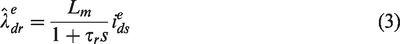
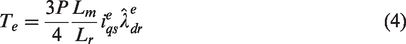
Adaption of equations (1) and (2) as the state matrix at the stationary reference coordinate frame (
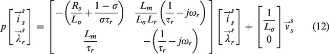
In accordance with the second row of equation (12), the current-model rotor-flux estimator can be defined as
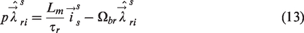

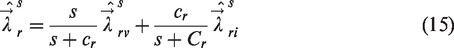
Based on equation (13), the current-model rotor-flux estimator is affected by variation of the rotor resistance at low-speed operation and by the variations of both rotor resistance and mutual inductance at high-speed operation. In accordance with equation (14), the voltage-model rotor-flux estimator is affected by variations of both stator voltage and stator resistance at low-speed operation but is less affected by variations of the motor parameters at high-speed operation. In this study, the estimated synchronous angle position is derived from the established current-and-voltage parallel-model rotor-flux estimator, which has the advantages of being less affected by variations of motor parameters and the capability of extending the available operation speed range. The current-and-voltage parallel-model rotor-flux estimator is expressed as equation (15). Here, the current-model and voltage-model rotor-flux estimators are adjusted by the low-pass and high-pass filters, respectively; the corresponding block diagram is shown in Figure 1.
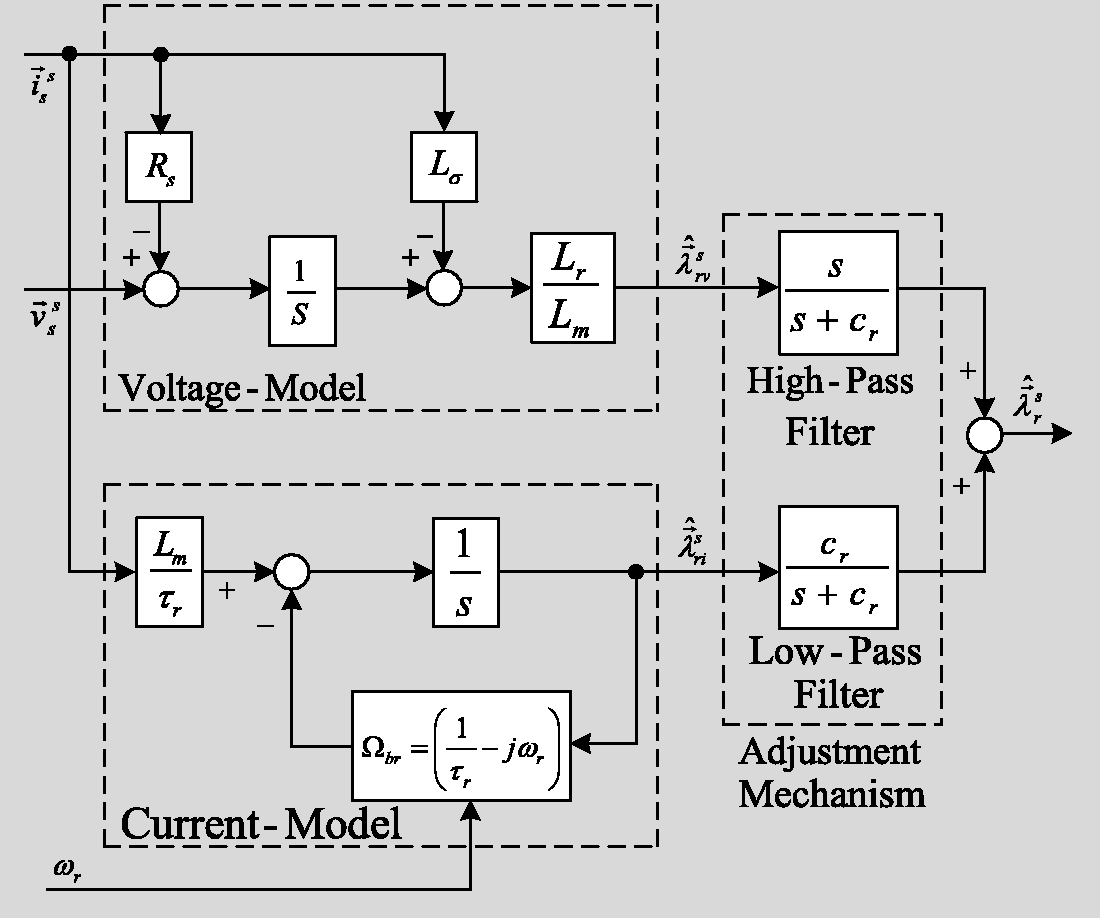
Current-and-voltage parallel-model rotor-flux estimator.
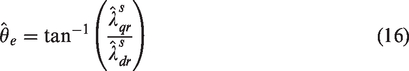
The estimated synchronous angular position, which is required for coordinate transformation between the synchronous reference coordinate frame and the stationary reference coordinate frame, is expressed as equation (16) and can be acquired from the current-and-voltage parallel-model rotor-flux estimator shown in Figure 1.
Lyapunov stability theory design rotor-flux observer
According to equation (12), the dynamic equations of an IM can also be expressed as


In accordance with equation (17), the estimation state equation of the proposed RFDOC IM drive is derived as

The estimation error is obtained by subtracting equation (19) from equation (17)

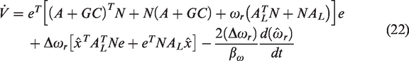
In accordance with Lyapunov stability theory,
18
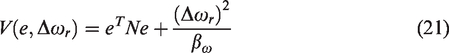
set

Select the adaptive law to be given by
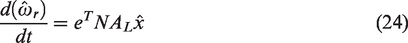
According to equation (24), the estimated rotor speed is given by

According to equation (19), the designed rotor-flux observer is given by
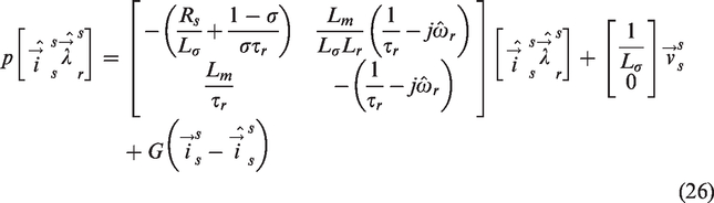
The proposed rotor-flux observer based on the measured stationary coordinate frame stator voltage (
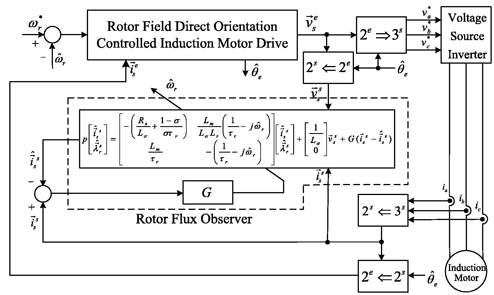
Senorless RFDOC IM drive based on the rotor-flux observer.
The PSO algorithm was utilized to acquire the gain matrix of the designed rotor-flux observer because it only requires allocation of a few parameters, has rapid convergence, and is suitable for a variety of conditions.
19
The PSO algorithm is a form of a swarm intelligence random searching algorithm and focuses on the information communication among the particles; the best solution of searching-speed can be improved by use of a concise mathematical model. In the PSO algorithm, the motion direction and distance of each particle is determined by the assigned velocity, and the fitness value of the assigned velocity is obtained from the fitness function. The velocity and position of each particle is updated by utilization of the iteration process, and the best solution can be obtained by using the cyclical computation until the number of maximum iteration is attained or the termination condition is satisfied. When every iteration process has been accomplished, the experience-sharing is implemented among particles and, according to the acquired improved fitness value of the particle individual, the best position of the individual is updated. When the best fitness value of the individual is superior to the best fitness value of the swarm, the best position of the swarm is also updated. Finally, according to the experience-sharing between an individual and swarm, the particle is guided toward the best solution direction. The updated velocity and position formula of the particle are given by


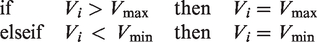
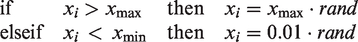
The prescribed boundary is necessary to prevent the updated velocity and position of the particle from exceeding the searching space-range. In this study, the constraint for the updated velocity of the particle is expressed as
The computation procedures of the proposed PSO algorithm are given as follows:
Step 1:In a d-dimension space, the position of the particle is randomly produced to allocate its velocity.
Step 2:The fitness value is computed by utilizing a fitness function for each particle.
Step 3:The present position of the particle is compared with the experienced best position of the individual
Step 4:The present position of the particle is compared with the experienced best position of the swarm
Step 5:The velocity and position of the particle are updated by using equations (27) and (28), respectively.
Step 6:Return to Step 2; perform in turn the cyclic computation until the prescribed maximum iteration value is achieved or the terminated condition is satisfied.
The flow chart of the proposed PSO algorithm is shown in Figure 3.
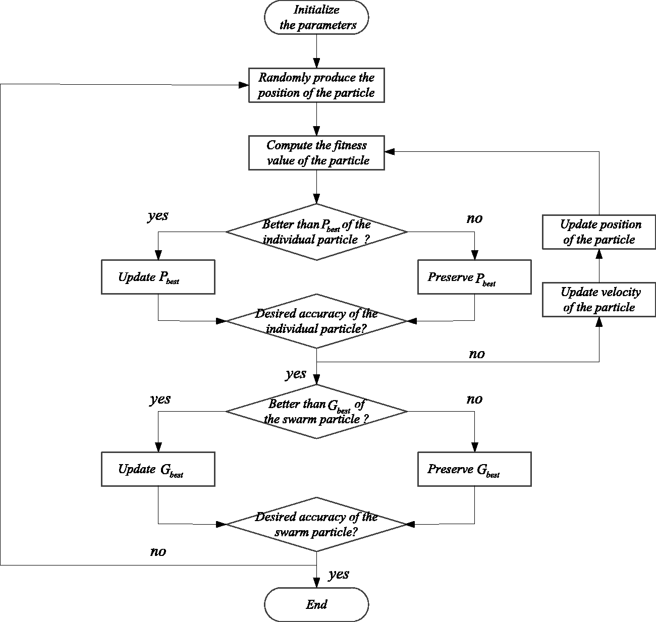
Flow chart of the proposed PSO algorithm.
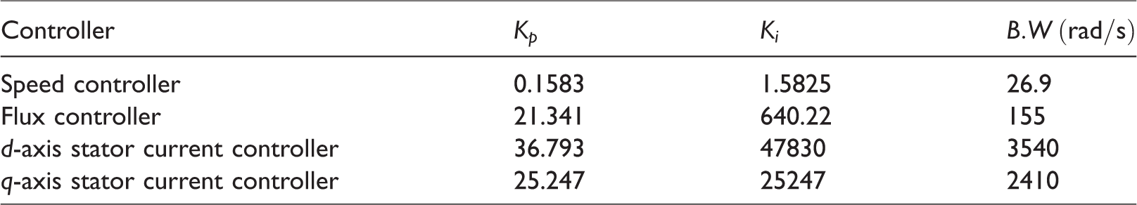
The block diagram of the proposed sensorless current-and-voltage parallel-model RFDOC IM drive based on the PSO algorithm rotor-flux observer is shown in Figure 4. The system includes the following: speed controller, flux controller, q-axis and d-axis stator current controllers, reference flux calculation, d-axis stator voltage decoupling, q-axis stator voltage decoupling, coordinate transformation, current-and-voltage parallel-model rotor-flux estimator, and rotor-flux observer. In this system, the proportion–integral (P-I) type controllers for the speed control loop, flux control loop, d-axis, and q-axis stator current control loops were designed based on the root-locus method. The proportion gain (
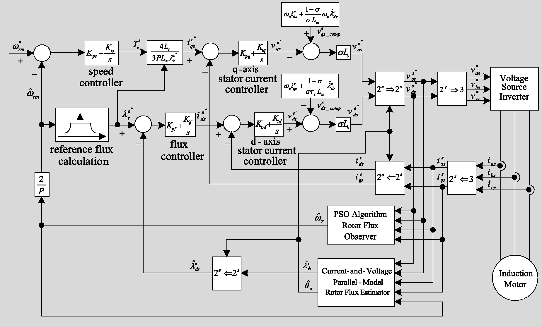
Sensorless current-and-voltage parallel-model RFDOC IM drive based on the PSO algorithm rotor-flux observer.
Controller parameters and its bandwidth.
Simulation and Experimental
A standard three-phase, 220 V, 0.75 kW, Δ-connected, squirrel-cage IM was used in the experiments to confirm the effectiveness of the proposed sensorless current-and-voltage parallel-model RFDOC IM drive based on the PSO algorithm rotor-flux observer. In a test running cycle, the speed commands were as follows: forward direction acceleration from
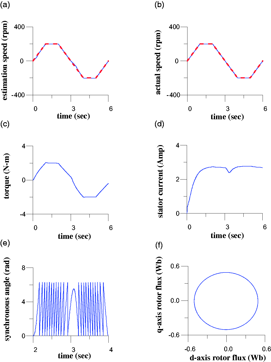
Simulated responses of the proposed sensorless RFDOC IM drive with a 2 N-m load and steady-state speed command ±200 r/min; (a) command (solid line) and estimated (dotted line) rotor speed, (b) command (solid line) and actual (dotted line) rotor speed, (c) electromagnetic torque, (d) stator current, (e) synchronous angle, (f) rotor-flux locus (q-axis vs. d-axis).
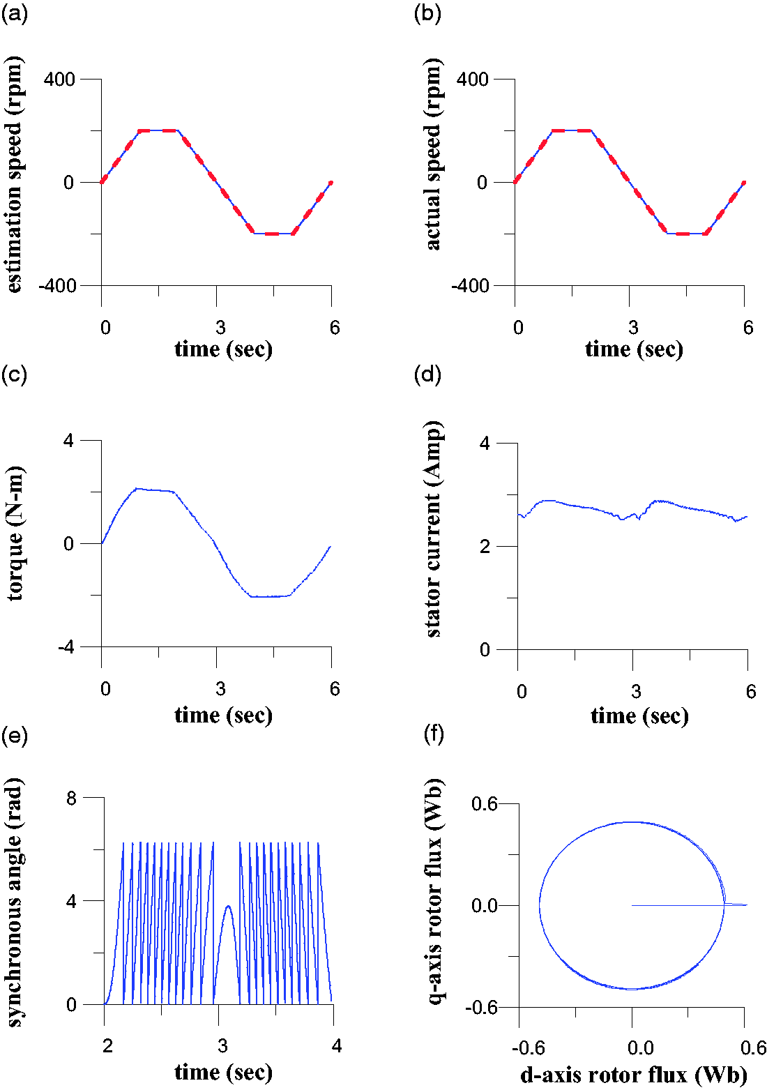
Measured responses of the proposed sensorless RFDOC IM drive with a 2 N-m load and steady-state speed command ±200 r/min; (a) command (solid line) and estimated (dotted line) rotor speed, (b) command (solid line) and actual (dotted line) rotor speed, (c) electromagnetic torque, (d) stator current, (e) synchronous angle, (f) rotor-flux locus (q-axis vs. d-axis).
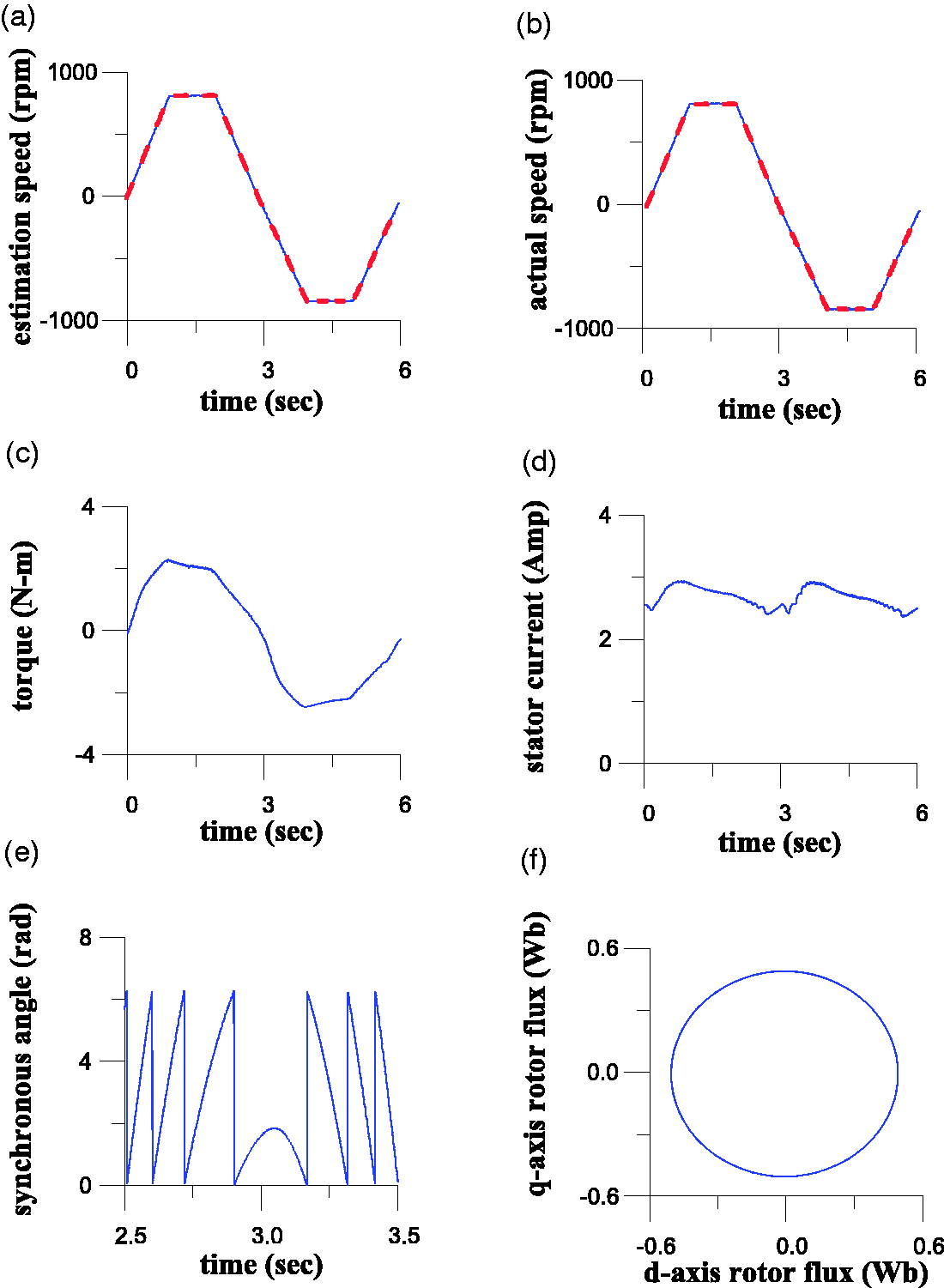
Simulated responses of the proposed sensorless RFDOC IM drive with a 2 N-m load and steady-state speed command ±800 r/min; (a) command (solid line) and estimated (dotted line) rotor speed, (b) command (solid line) and actual (dotted line) rotor speed, (c) electromagnetic torque, (d) stator current, (e) synchronous angle, (f) rotor-flux locus (q-axis vs. d-axis).
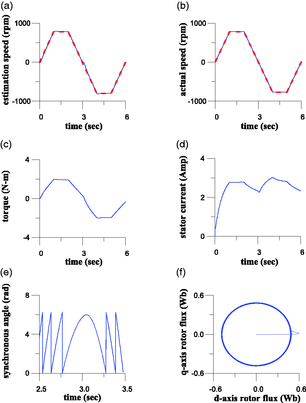
Measured responses of the proposed sensorless RFDOC IM drive with a 2 N-m load and steady-state speed command ±800 r/min; (a) command (solid line) and estimated (dotted line) rotor speed, (b) command (solid line) and actual (dotted line) rotor speed, (c) electromagnetic torque, (d) stator current, (e) synchronous angle, (f) rotor-flux locus (q-axis vs. d-axis).
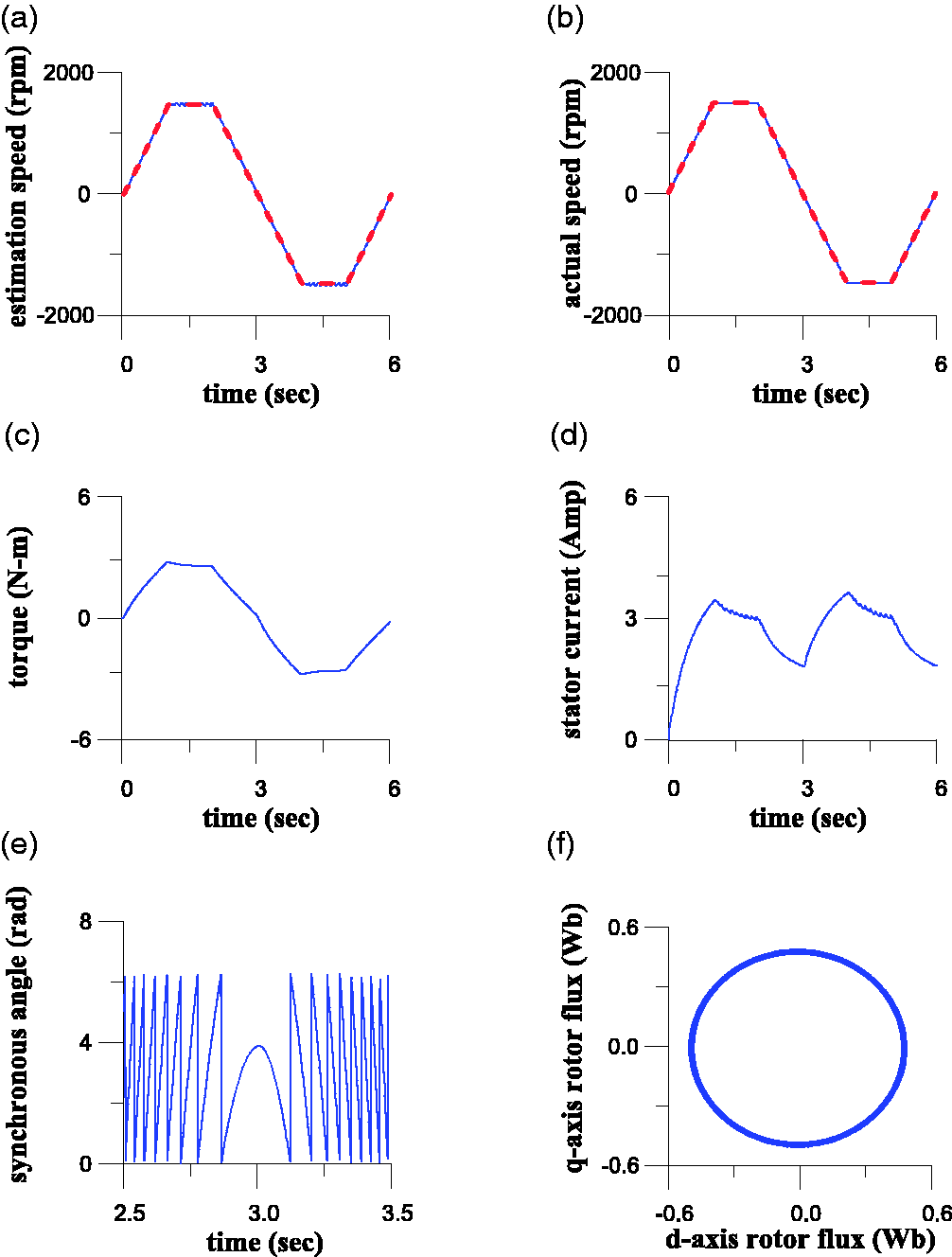
Simulated responses of the proposed sensorless RFDOC IM drive with a 2 N-m load and steady-state speed command ±1600 r/min; (a) command (solid line) and estimated (dotted line) rotor speed, (b) command (solid line) and actual (dotted line) rotor speed, (c) electromagnetic torque, (d) stator current, (e) synchronous angle, (f) rotor-flux locus (q-axis vs. d-axis).
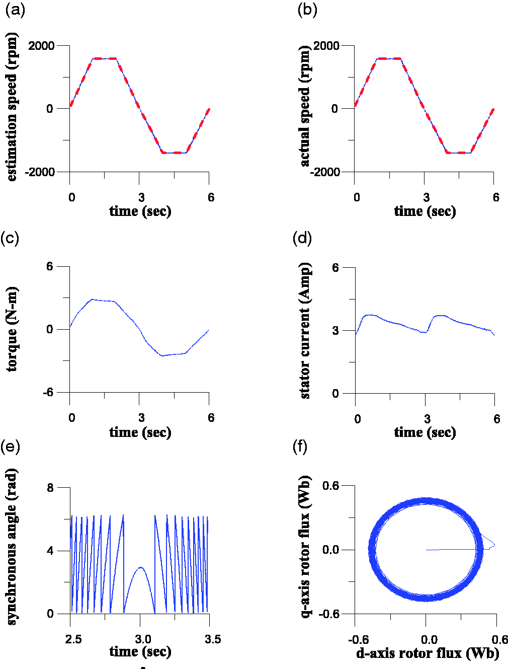
Measured responses of the proposed sensorless RFDOC IM drive with a 2 N-m load and steady-state speed command ±1600 r/min; (a) command (solid line) and estimated (dotted line) rotor speed, (b) command (solid line) and actual (dotted line) rotor speed, (c) electromagnetic torque, (d) stator current, (e) synchronous angle, (f) rotor-flux locus (q-axis vs. d-axis).
The simulations and experimental results for different speeds are shown in Figures 5 to 10. Estimations of the accuracies of the reversible rotor speed (including acceleration, steady-state, and braking operation) were obtained. The stator current and electromagnetic torque showed excellent responses. The synchronous angle and circular shape of the rotor-flux locus show the estimated synchronous angle position for execution coordinate transformation to be exact. Excellent performance could clearly be achieved using the proposed sensorless current-and-voltage parallel-model RFDOC IM drive based on the PSO algorithm rotor-flux observer.
Conclusions
The Lyapunov stability theory based design of a rotor-flux observer speed estimation scheme that uses the PSO algorithm was described, and a current-and-voltage parallel-model rotor-flux estimator synchronous angle position estimated scheme was implemented to obtain the exact coordinate transformation between the synchronous and stationary reference coordinate frame for sensorless RFDOC IM drives. The simulated and experimental responses for the estimated rotor speed, electromagnetic torque, stator current, estimated synchronous angle position, and rotor-flux locus at different reversible steady-state speeds (±200 r/min, ±800 r/min, and ±1600 r/min) confirmed the effectiveness of the proposed approach.
Footnotes
Declaration of conflicting interests
The author(s) declared no potential conflicts of interest with respect to the research, authorship, and/or publication of this article.
Funding
The author(s) received no financial support for the research, authorship, and/or publication of this article.