
Abstract
Resolving the trade-offs between suspension travel, ride comfort, road holding, vehicle handling and power consumption is the primary challenge in the design of active vehicle suspension system. Multi-loop proportional + integral + derivative controllers’ gains tuning with global and evolutionary optimization techniques is proposed to realize the best compromise between these conflicting criteria for a nonlinear full-car electrohydraulic active vehicle suspension system. Global and evolutionary optimization methods adopted include: controlled random search, differential evolution, particle swarm optimization, modified particle swarm optimization and modified controlled random search. The most improved performance was achieved with the differential evolution algorithm. The modified particle swarm optimization and modified controlled random search algorithms performed better than their predecessors, with modified controlled random search performing better than modified particle swarm optimization in all aspects of performance investigated both in time and frequency domain analyses.
Keywords
Introduction
Good active vehicle suspension system (AVSS) is a control challenge in the design of vehicle suspension systems. The challenge includes the determination of the optimal trade-offs between conflicting suspension performance parameters like suspension travel, ride comfort, road holding and vehicle handling. For example, compromise must be reached when a hard suspension with limited suspension travel is required for good road holding, and a soft suspension is desired for a smooth and comfortable ride.
Another challenge faced in designing control system for AVSS is its nonlinear characteristics, especially due to complex dynamics of the electrohydraulic actuators.1,2 Meanwhile the system is highly prone to operational and system uncertainties. The full-car is characterized by nonlinear coupling and multiple-variable control situation.3–5
Whilst the superior performance of active suspension is not in doubt, it is unable to claim similar level of commercial acceptability like passive vehicle suspension systems (PVSSs), because it is more complex operationally and structurally.6–8 Recent technological growth is creating opportunities for implementation of complex control methodologies in AVSS design. Linear optimal control schemes are well developed and already employed in the controller designs for AVSS and semi-active vehicle suspension systems.8–17 Stability and robust characteristics are well established for these techniques, but these properties become highly limited when implemented in nonlinear AVSS. 18
Successful application usually depends on availability of good dynamic model of the system and availability of all the states. Implementation of nonlinear techniques like feedback linearization requires guarantee of stable zero dynamics in the system; backstepping requires repeated differentiation of the system’s nonlinear function and their implementation practically is usually characterized by chattering.19–23 Combining nonlinear control schemes with computational intelligence techniques have largely been demonstrated to be effective, 24 but it comes with the additional computational complexity that is associated with each scheme in the process. Demonstrating system stability can also be very challenging.25,26
The case for application of proportional + integral + derivative (PID) control design to AVSS has been made and demonstrated. 5 Control design for full-car AVSS in this work requires a cascaded feedback loop arrangement with inner loops stabilizing the actuator dynamics with several PID feedback control loops to tune simultaneously in a system characterized by couplings amongst its parameters; employment of global and evolutionary algorithms for autotuning cannot be avoided. Its potentials have been documented already in the literature.27–36 Benefit of this approach is that the optimization algorithms can use their objective functions to satisfy specified or required performance criterion.
Controlled random search (CRS) and differential evolution (DE) have been successfully used to compute optimal parameters for various nonlinear systems and engineering applications.37–40 Classical particle swarm optimization (PSO)-tuned PID control has been employed in many control designs. Though it was initially designed for continuous space, it performs well when applied to discontinuous objective functions. However, it is prone to premature convergence in large-scale complex problems like most of the other stochastic algorithms.35,36
The solution space in this research is expected to contain many peaks and troughs as the system is highly nonlinear with seven degree-of-freedom (DOF), thereby making the optimization process more challenging. Good AVSS designs require adaptive control properties in spite of the complex computation demands that arise through the use of sophisticated control methods. PID controllers tuned using global and evolutionary algorithms are able to take up this advantage, thereby controlling with some level of intelligence. 35
The setbacks found in the performances of the algorithms are used in modifying them for better performances. These modifications are, however, uniquely suitable for particular problems.
36
In this work, modified variants of CRS and PSO routines are introduced to address their shortcomings. For example, for PSO, for the ith particle xi, instead of exploring the area around the vicinity of each particle best solution Pi, exploration will be conducted around any randomly selected particle Ri that has a better fitness value than the particle of interest, i.e.
In the modified CRS, the underlining centre of gravity will be based on only a few randomly selected individuals instead of the whole population. For example, instead of creating a simplex using n + 1 solutions (where n solutions are chosen randomly), one being the overall best, a simplex using only three solutions is created. The worse of the three is reflected through the centre of gravity of the remaining two. This will add flexibility to the algorithm and improve the exploration capabilities of the algorithm. Hence, a comparative analysis will be performed to investigate the effects of these modifications.41,42
The major contributions of the paper are as follows:
Selection of the cascaded PID controllers’ parameters for the seven DOF nonlinear electrohydraulic AVSS using global and evolutionary optimization techniques to address the trade-offs amongst the conflicting performance requirements; and Frequency-domain analysis of the proposed DE-optimized, PID-based multi-loop controller within the whole-body vibration range of
Employment of five different global and evolutionary optimization shows the level of complexity and computational difficulty used in achieving the design of the PID-based controller in this work with 24 optimized parameters.
The rest of the paper is organized as follows. The next section presents a brief description of the physical, mathematical and road disturbance input models for the AVSS. ‘Controller implementation’ section presents the controller design, the system performance specifications and evaluation criteria. ‘Evolutionary and global optimization algorithms’ section describes in detail the global and evolutionary optimization algorithms. Simulation results and their discussion are presented in ‘Simulation results and discussion’ section. Concluding remarks are given in the final section.
System overview and modelling
Mathematical modelling
A schematic of the full-car model is presented in Figure 1 and the governing equations are derived using Newton–Euler methods.
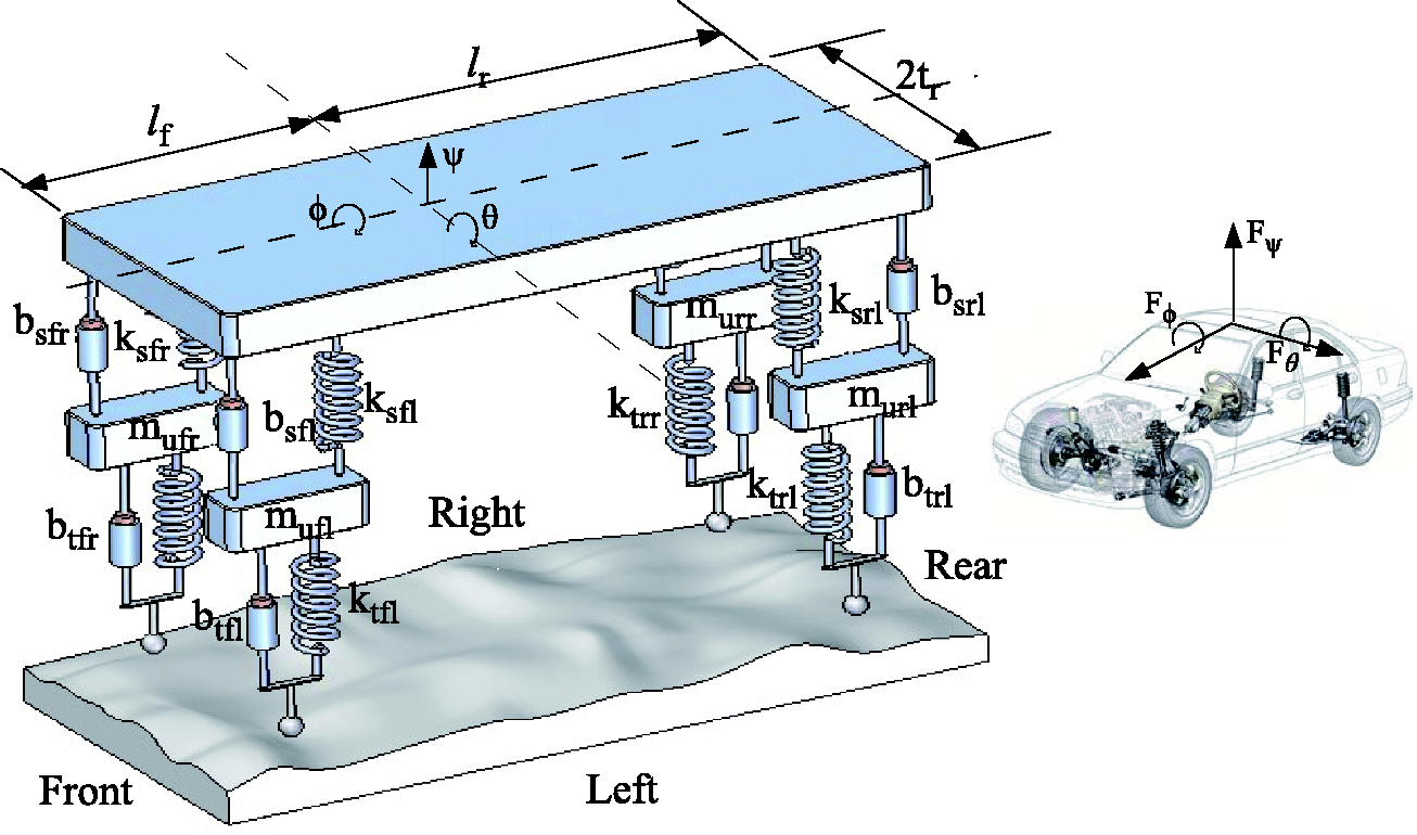
Simplified full-car model for AVSS.
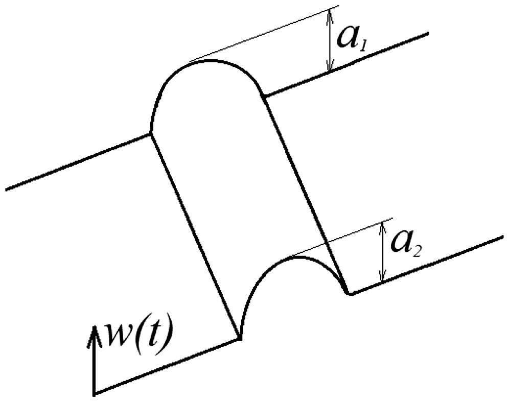
Road disturbance input for the full-car AVSS.
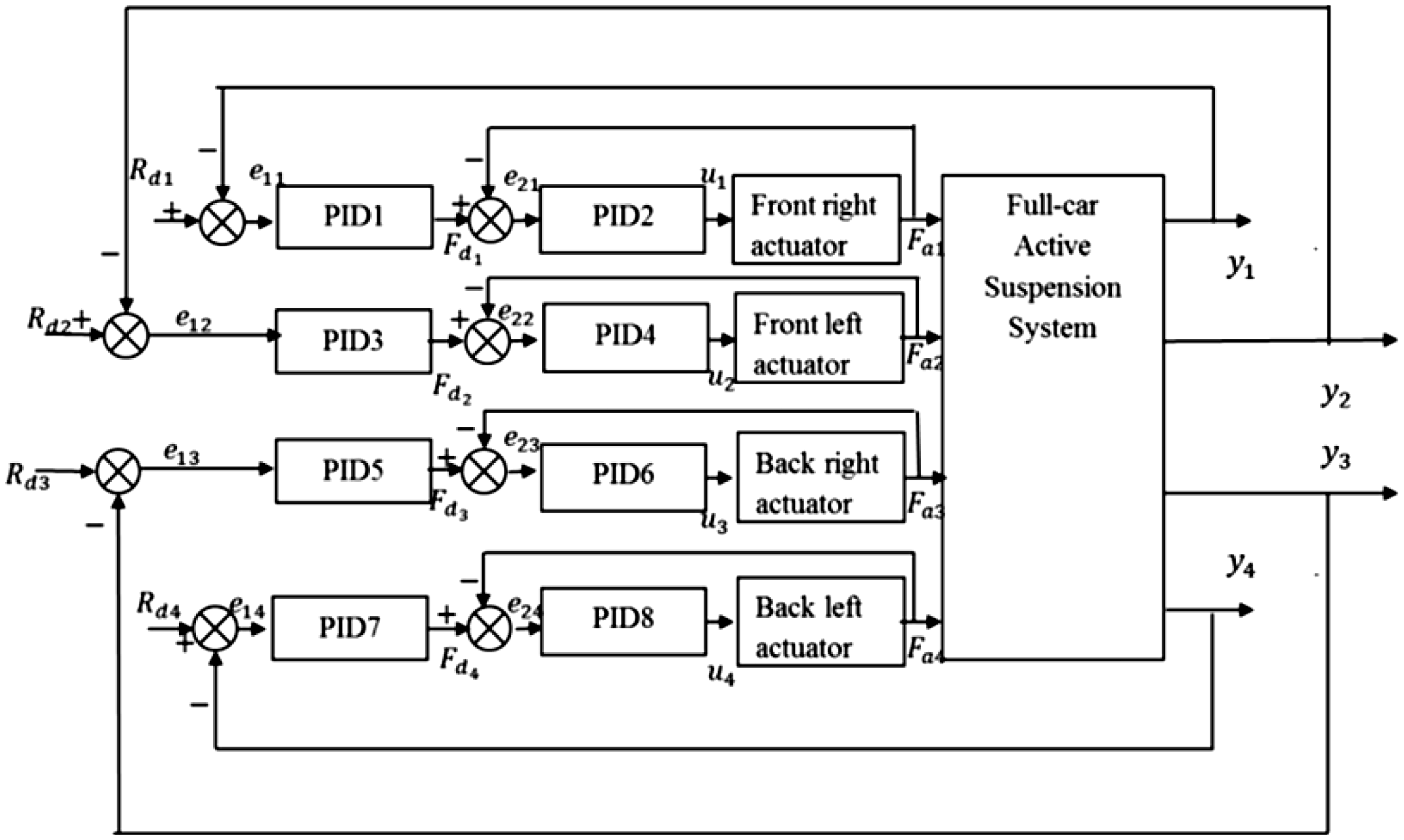
Control architecture of the proposed multi-loop PID controller. PID: proportional + integral + derivative.
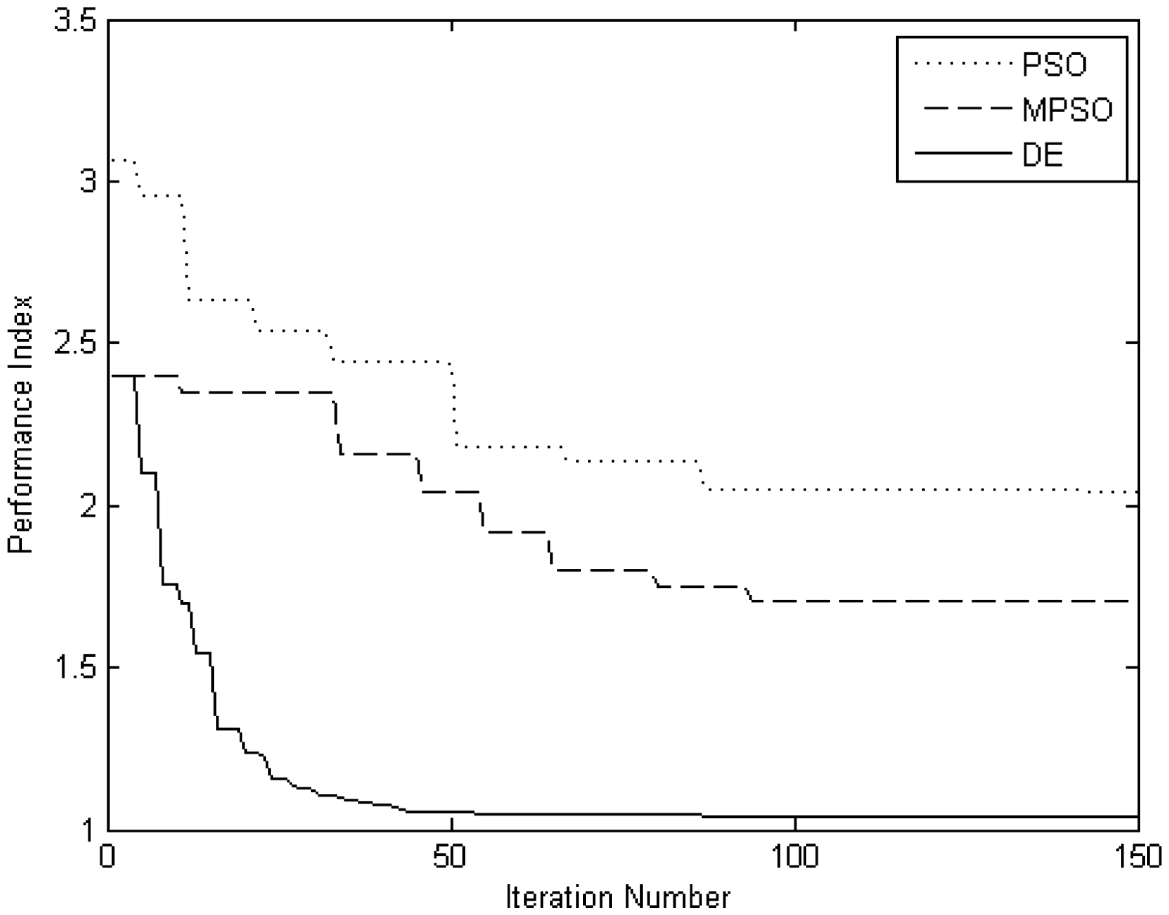
Convergence history plots for PSO, MPSO and DE. DE: differential evolution; MPSO: modified particle swarm optimization; PSO: particle swarm optimization.
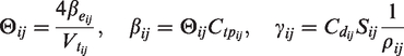
Vertical forces acting on the chassis are given as


The governing equation at each wheel is given as


The mathematical relations of the hydraulic actuator force are given as

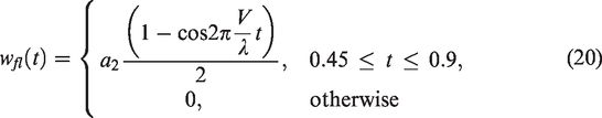
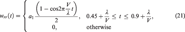
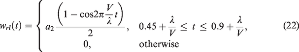
The heave, pitch and roll motions of the vehicle are induced by travelling over a bump which varies in height along its lateral length as shown in Figure 2. The road profile at each wheel is given as

Parameters of the full-car model.

Controller implementation
Figure 3 shows the architecture of the multi-loop PID control investigated in the present paper. It includes four outer loops to regulate the controlled variable and four inner force feedback loops are placed at each actuator to ensure stability of the hydraulic actuator. The control variable is the suspension travel as this output is the primary factor that captures the system dynamics. The outer control loops are modelled as follows


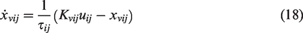
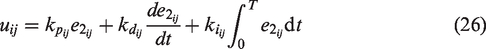
In a similar manner, the inner control loop determines the control voltage sent to the hydraulic actuator. The governing equations of these inner-loop controllers are as follows
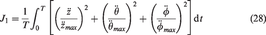
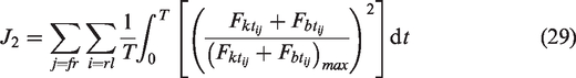
1. The controller should demonstrate a good low-frequency disturbance rejection; 2. Satisfactory transient response with minimal oscillations after the disturbance has disappeared; that is: • the rise time should not be greater than 0.1 s, • the maximum overshoot should be less than 5% • and zero steady-state error. 3. Suspension travels yij are constrained to a maximum of ±0.1 m. 4. Control input voltages uij are constrained to ±10 V due to the limitations of the power supply. 5. The total actuation force must be less than the vehicle weight to ensure that the vehicle does not leave the ground, i.e. 6. The body-heave acceleration ( 7. The performance index J which addresses each of the conflicting design criteria of an AVSS is to be minimized. This index has the following form

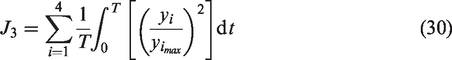
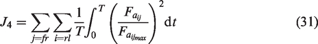
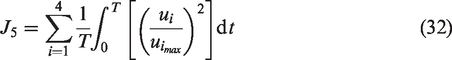
where J is the performance index and J1, J2, J3, J4 and J5 relate to the vehicle ride comfort and vehicle handling, road holding properties, suspension travel, actuation force and power consumption, respectively. 
Evolutionary and global optimization algorithms
Five optimal policies (CRS, DE, PSO, modified controlled random search (MCRS) and modified particle swarm optimization (MPSO)) will be used to select the controllers’ gains for the full-car AVSS. In this section the resulting AVSS performance and the performance of the optimal routines relative to one another will be studied. The objective function has the form presented in equations (27) to (32). The rest of this section will be devoted to describing the algorithms.
DE optimization algorithm
Evolutionary algorithms which include DE, GA and PSO are random search optimization methods where the optimal solution is produced through the evolution of a random population set
In each generation step of DE, an associated trial individual 
Crossover is thereafter performed between the targeted individual 
The trial vector Create a mutated individual Compute the trial candidate Replace the ith individual Repeat the process for each individual within S and return to step 2.
We have used
PSO algorithm
In the case of PSO, the search space is reflected as an n-dimensional world (n represents the number of parameters being optimized) where swarms of animals or particles of a random population set 
The velocity at which each particle travels in each direction depends on the particle’s previous velocity in that specified direction, the corresponding position of the fittest particle in that direction and on the corresponding position of the particle’s personal best position. To record the personal best results of each particle, the matrix
In each iteration, every particle converges to some extent towards both the fittest individual in the population 
By changing the position of each particle according to the aforementioned equations, each particle has the potential to improve upon its personal best location and has the ability to become the global best particle. Hence after each iteration, the fitness value of each particle is analysed and if it improves from its personal best solution, its personal best location is replaced with its current location. This is further explained as follows
Produce a random swarm of particles Define the global best particle as the fittest particle in the swarm and let the personal best particles be the same as the initial population. If stopping criterion is met, i.e. Kmax iterations are performed, advance to step 7, or else carry on to next step. Calculate the new set of positions For each particle perform the following actions: If the fitness of the newly computed particle is better than its personal best location, then replace the personal best particle’s location with those of the newly computed particle as described by equation (38). Register the best particle in the personal best matrix as the global best particle using equation (39). Use the global best particle as the optimal solution.

We have used
CRS optimization algorithm
First, an initial population 
This candidate solution 
After the above steps are completed, the procedure is continued until the stopping criterion is met.
46
The procedure for CRS global optimization algorithm is summarized in the following steps:
We have used n = 60, kmax = 6000 and N = 240.
MPSO
To explain the modification and its resulting impact in comparison to the PSO, the analogy of a swarm of particles in 2D search space with two variables is presented. Further study of both the PSO governing equations presented in equations (36) and (37), several inferences can be made regarding convergence basis of the local search.
According to the PSO equations, each particle is programmed to search for the optimal solution in the vicinity of its personal best solution, in the region around the particle in the solution space which has the best solution, whilst subjected to the momentum of its velocity from the previous iteration. The resultant position vector is denoted as
The resultant vector and hence the resulting particle position may be considerably swayed by the local search vector based on the ratio
In accordance with this reasoning, it would be appropriate to alter equation (37) by replacing the personal best position 
We have used
MCRS
In the fundamental CRS equations presented in equations (40) to (42) the centre of gravity
To overcome this shortfall, three random individuals will be selected from the solution space S, as opposed to the n + 1 individuals that were previously chosen, these individuals will be in ascending order according to their fitness values with 
By doing so, the flexibility of the
We have used n = 3, kmax = 6000 and N = 240.
Analysis of the convergence of the various routines
The convergence histories of the fitness value using the proposed optimal routines are plotted in Figures 4 and 5. The MCRS and MPSO algorithms outperformed their predecessors with improved fitness value and quicker convergence. Hence, it may be concluded that the suggested modifications made improved the respective policies, with the CRS becoming more flexible and the PSO showing better convergence of weaker particles.
Performance of the CRS routines may also be evaluated in terms of success rate, which is measured as the ratio of how often the weakest individual in the population 
The resulting success rate for the CRS was 0.075 and that of the MCRS was 0.15. This infers that the MCRS produces more improved solutions than the CRS.
Figures 4 and 5 show that the suggested modifications in CRS and PSO routines yielded superior results. Altering the local search characteristics of each particle in the PSO method improved the effectiveness and efficiency of the algorithm. It may also be concluded that increasing the flexibility of CRS using the proposed method outlined in ‘CRS optimization algorithm’ section added value to the algorithm with a better success rate and prevented early convergence and produced a better resulting fitness value. The DE algorithm produced the best results followed by MPSO and MCRS, respectively. The controller gains computed by these superior algorithms in addition to the manually tuned controller are listed in Tables 2 and 3. The inner-loop derivative controllers’ gains kd are of a small order of magnitude and may be ignored for practical purposes.
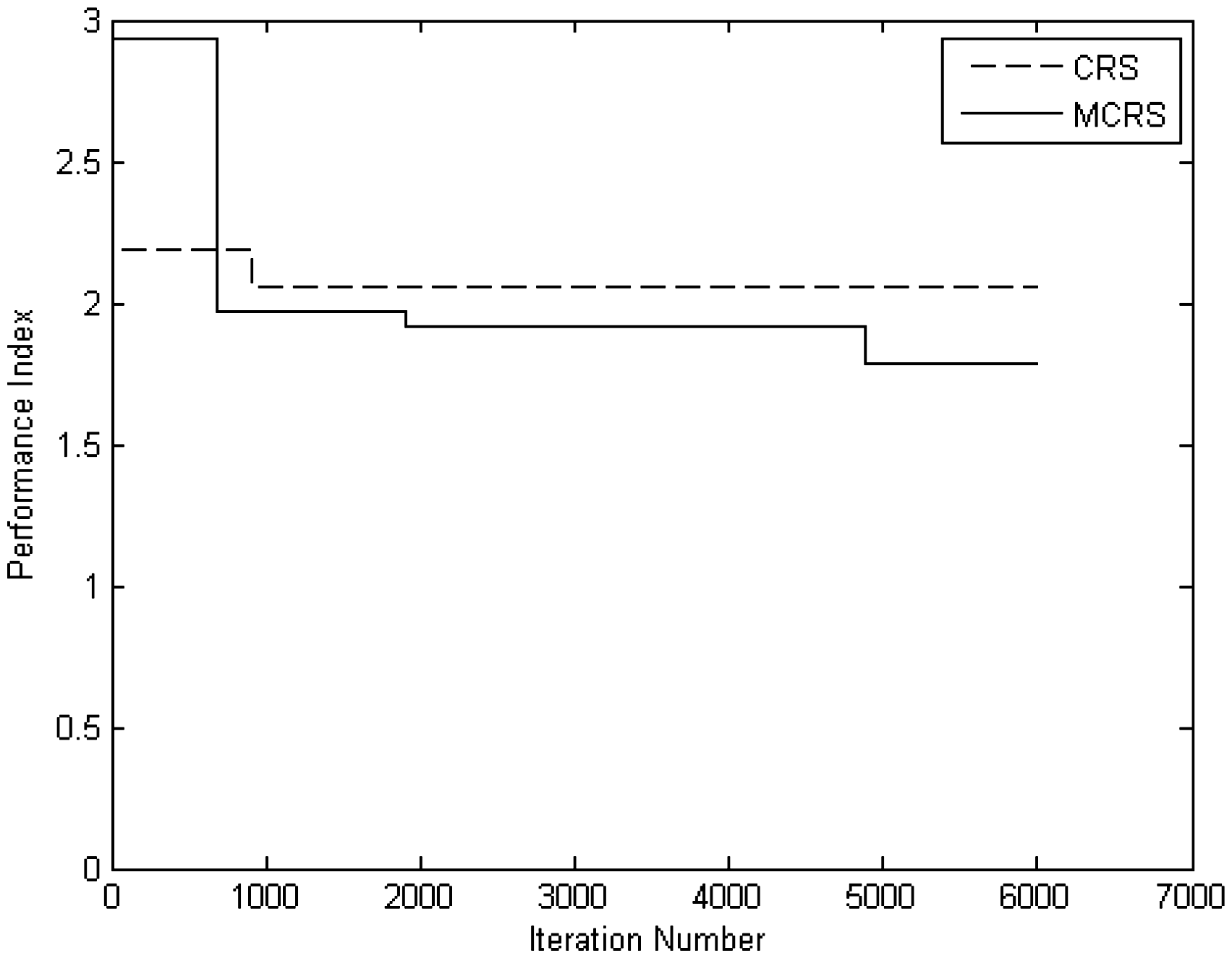
Convergence history plots for CRS and MCRS. CRS: controlled random search; MCRS: modified controlled random search.
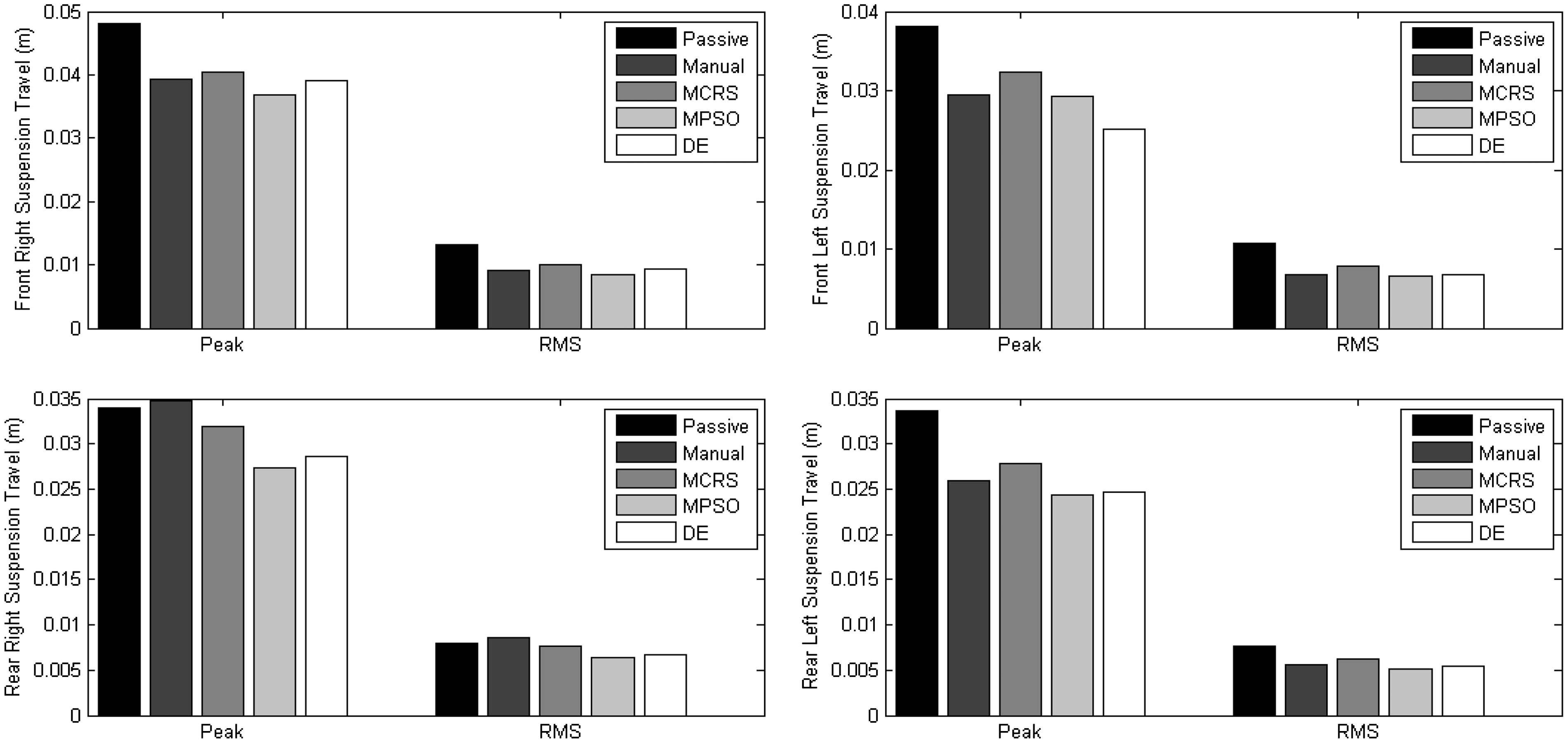
Bar graphs depicting the variation in suspension travel for each control law. DE: differential evolution; MCRS: modified controlled random search; MPSO: modified particle swarm optimization; RMS: root-mean-square.
Gains computed using the various optimization algorithms for front suspensions of the PID-controlled AVSS.
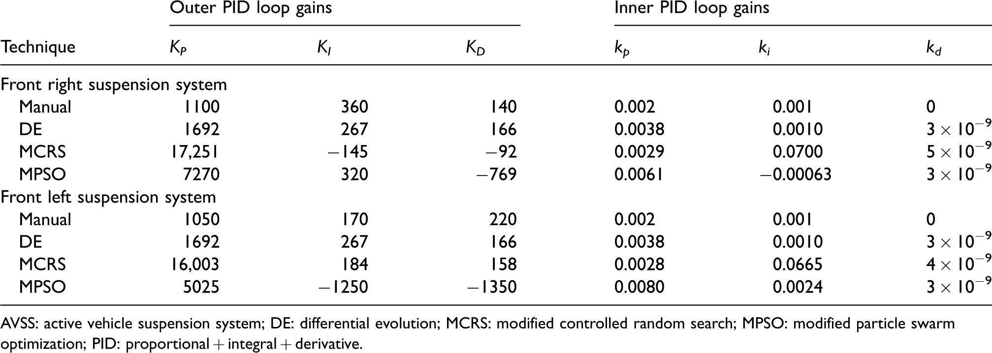
AVSS: active vehicle suspension system; DE: differential evolution; MCRS: modified controlled random search; MPSO: modified particle swarm optimization; PID: proportional + integral + derivative.
Gains computed using the various optimization algorithms for rear suspensions of the PID-controlled AVSS.
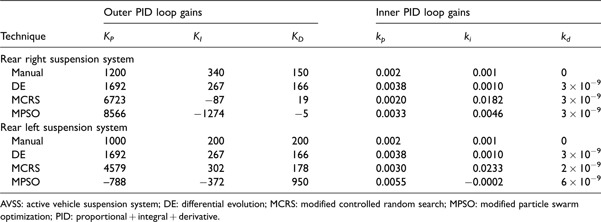
AVSS: active vehicle suspension system; DE: differential evolution; MCRS: modified controlled random search; MPSO: modified particle swarm optimization; PID: proportional + integral + derivative.
Simulation results and discussion
The evolutions of the performance index through the use of the proposed tuning algorithms presented in Figures 4 and 5 show that the DE routine gave the best performance index followed by the MPSO and MCRS algorithms, respectively. However, these plots cannot provide information on how well the suspension trade-offs have been resolved. Hence plots for each suspension performance criterion will be plotted for the non-optimized, DE, MCRS and MPSO cases, respectively.
Simulations were performed in the Matlab/Simulink environment and the simulation time was set to 5 s. Suspension travel performance, road holding (tyre dynamic load) and power consumption (control input voltage) are plotted in Figures 10 to 15, respectively. These plots focus on the rear left suspension corner only as the worst performance behaviour was observed at this location. Vehicle handling (roll and pitch accelerations) is presented in Figures 12 and 13, respectively. Ride comfort (body-heave acceleration) is shown in Figure 14 and the cumulative hydraulic force applied to the vehicle body is plotted in Figure 16. The peak and RMS values pertaining to these quantities are compared in Figures 6 to 9.
The suspension travel response obtained when implementing each of the optimal routines displayed reduced peak and RMS values in comparison with PVSSs and manually tuned PID cases, respectively. They showed better transient behaviour by damping out with no further peaks immediately after the road disturbance was removed. These results were anticipated as the performance index did indeed address suspension travel with a fair and considerable weighting factor.
The road holding capabilities acquired for DE and MCRS cases were similar and superior to those of the PVSSs and manually tuned cases with lower peaks, better RMS values, quicker settling times and improved transient response that had fewer peaks and reduced oscillations. On the other hand, the MPSO case did manage to improve the RMS value, transient behaviour and settling time, but still produced the largest peak values. However, even with the inter-relationship between RMS and peak values, it is not guaranteed that reducing the RMS value will always reduce the peak values and hence such a shortfall is possible.
Regarding vehicle handling and ride comfort, the optimal policies produced lower peak and RMS values with quicker settling times than those of the manually tuned AVSS and PVSSs. However, each policy contained a greater degree of chattering which would tend to deteriorate system components. In terms of ride comfort and handling performance, the MPSO case was the worst from the optimal methods followed by the MCRS and DE cases, respectively. Its weak performance is due to the fact that this routine produced a lower performance index value as compared to the DE case. It is worth noting that although MCRS had a similar performance index, it did perform adequately in vehicle handling, but lacked quality in suspension travel. In conclusion, both algorithms produced a weaker performance index than DE, but they did exhibit desired responses in certain performance aspects whilst performing weaker in other aspects. This implies that these algorithms were not as good as the DE in resolving the trade-offs between the various performance criteria. Furthermore, DE produced the best performance index which was approximately 40% better than its counterparts.
The comparative plot pertaining to control input voltage and cumulative hydraulic force showed that all the optimal tuning policies produced lower peak and RMS values than the manually tuned case whilst at the same time they were able to enhance the RMS values and response of ride comfort, road holding and vehicle handling criteria. From a computational standpoint, this is projected as control input voltage and supplied hydraulic forces are substantial factors of the performance index. However, from an engineering point of view, such data are rather contradictory to both typical quarter-car models and linear control techniques as a larger force or voltage is demanded to improve the various performance benchmarks. These results infer that the coupling and nonlinearities of the full-car nonlinear system is a major factor that supplements the outcomes of the system and it is thus imperative that they are thoroughly investigated.
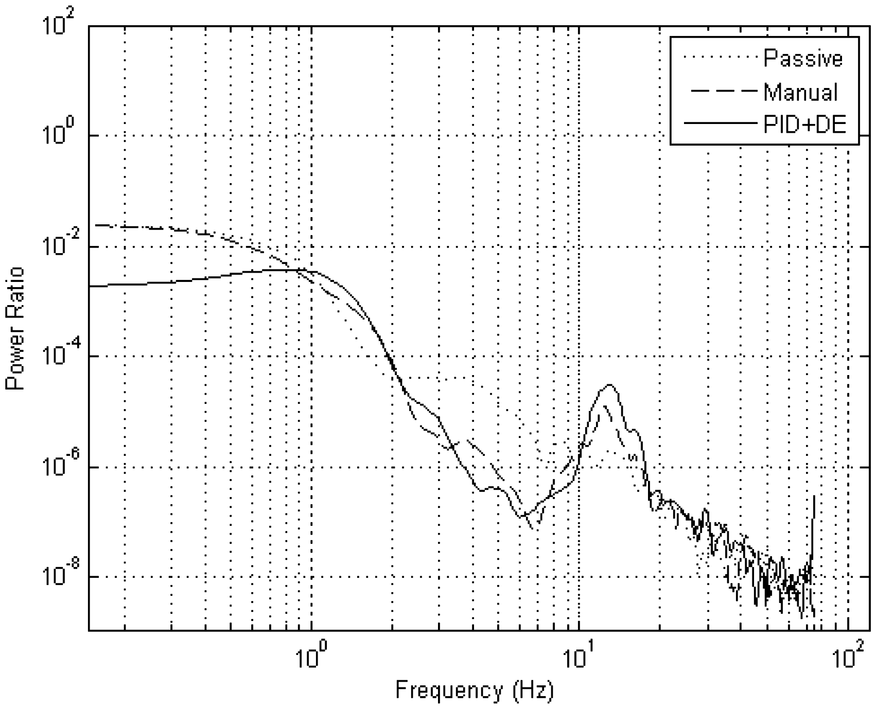
Frequency-domain analysis
The ISO 2631
44
states that human exposure to frequencies ranging from 0.5 to 80 Hz significantly affects human comfort. Thus, it is imperative that relevant AVSS performance criteria be analysed in this range. Bode plots pertaining to ride comfort, vehicle handling and road holding for the PVSSs, manually tuned PID and DE-optimized PID cases are illustrated in Figures 17 to 20. These plots were generated using the power spectral density estimates based on Welch algorithm in the Matlab/Simulink signal processing toolbox. The following parameters are used in computing the Welch’s periodograms: the windowing function–Hanning window function; the number of points used in forming each fast Fourier transform, NFFT
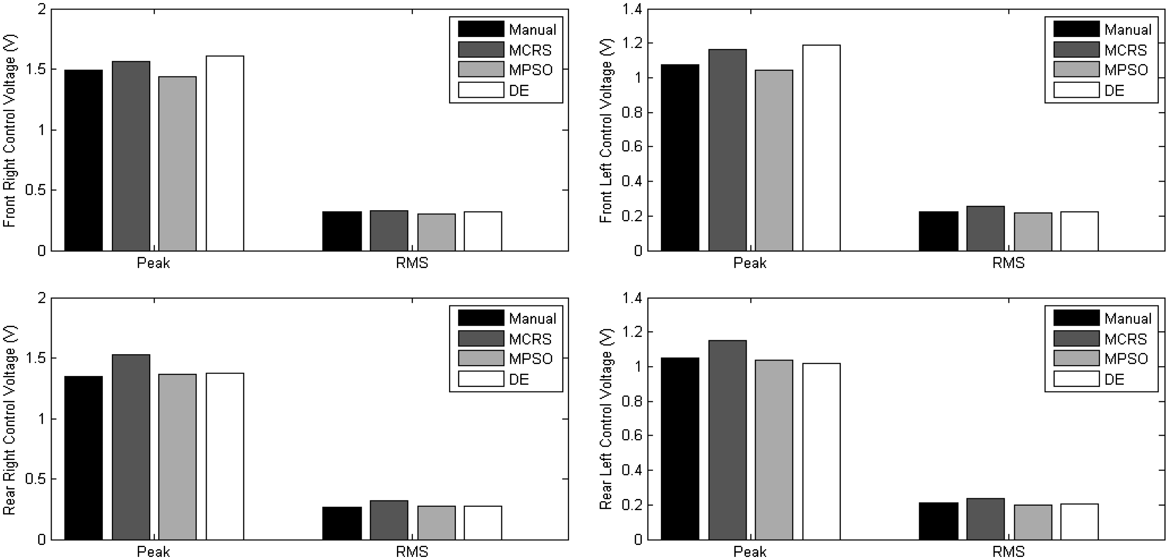
Bar graphs illustrating the difference in control input voltage for the proposed controllers. DE: differential evolution; MCRS: modified controlled random search; MPSO: modified particle swarm optimization; RMS: root-mean-square.
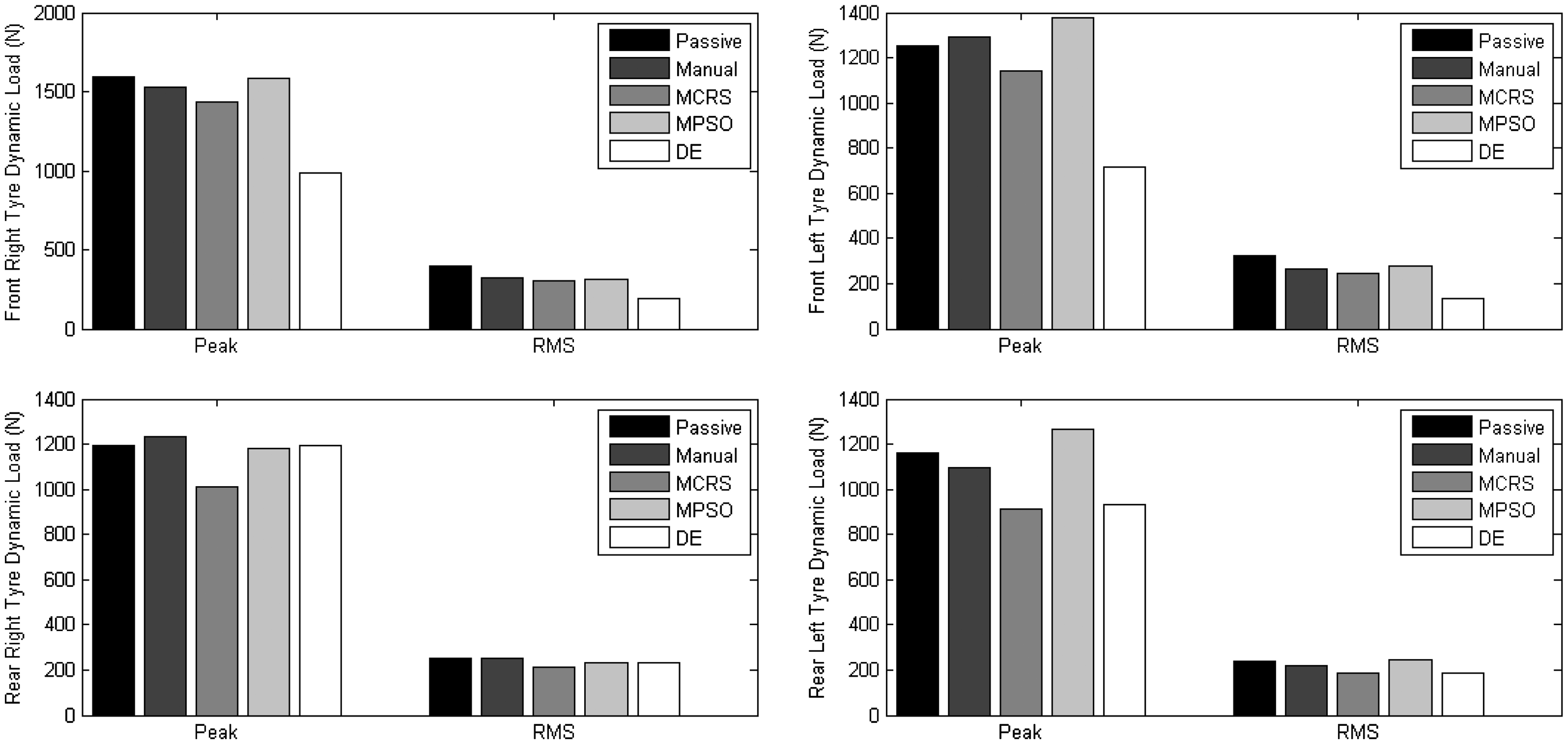
Bar graphs summarizing the road holding aspect for each control case. DE: differential evolution; MCRS: modified controlled random search; MPSO: modified particle swarm optimization; RMS: root-mean-square.
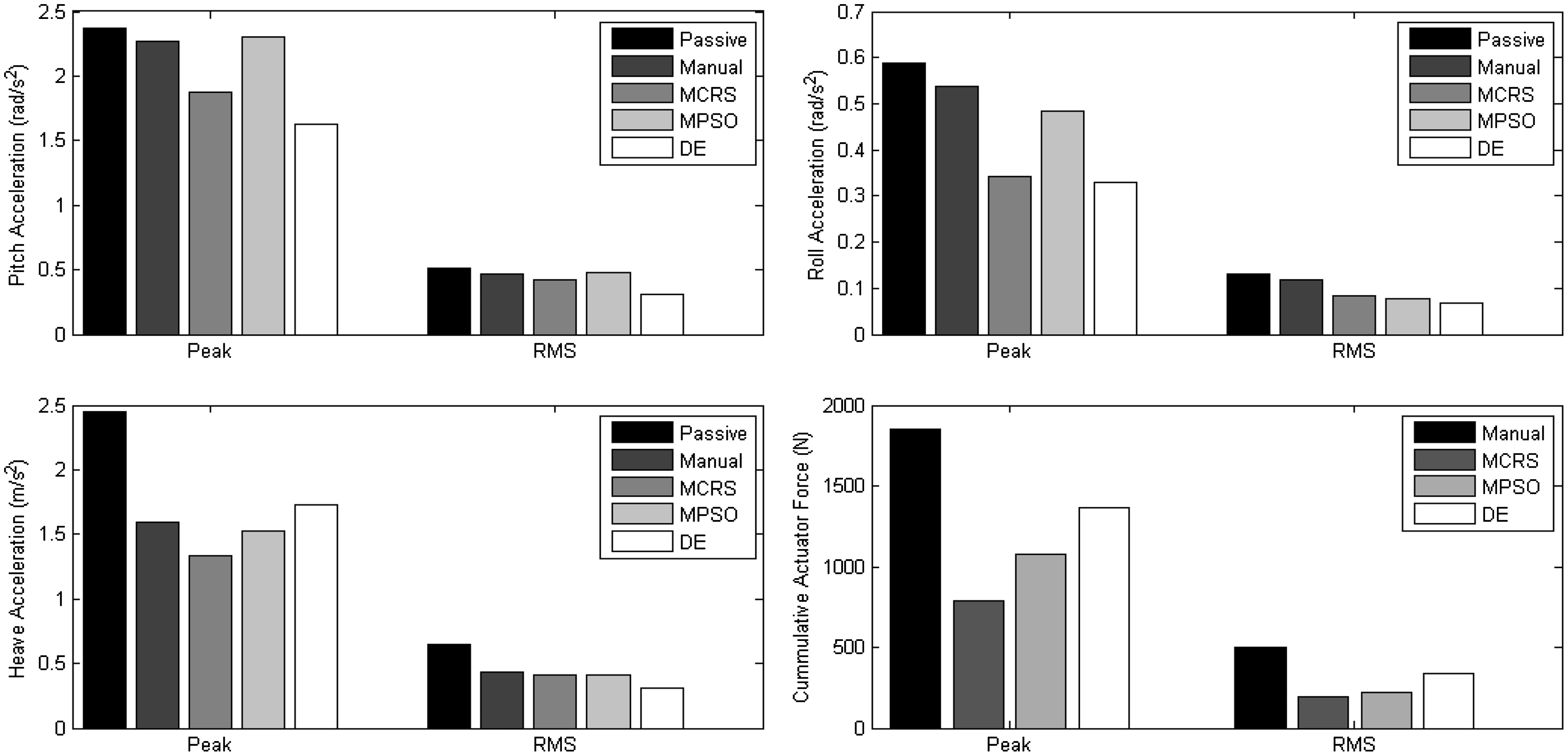
Quantitative information pertaining to vehicle handling, ride comfort and actuator force supplied. DE: differential evolution; MCRS: modified controlled random search; MPSO: modified particle swarm optimization; RMS: root-mean-square.
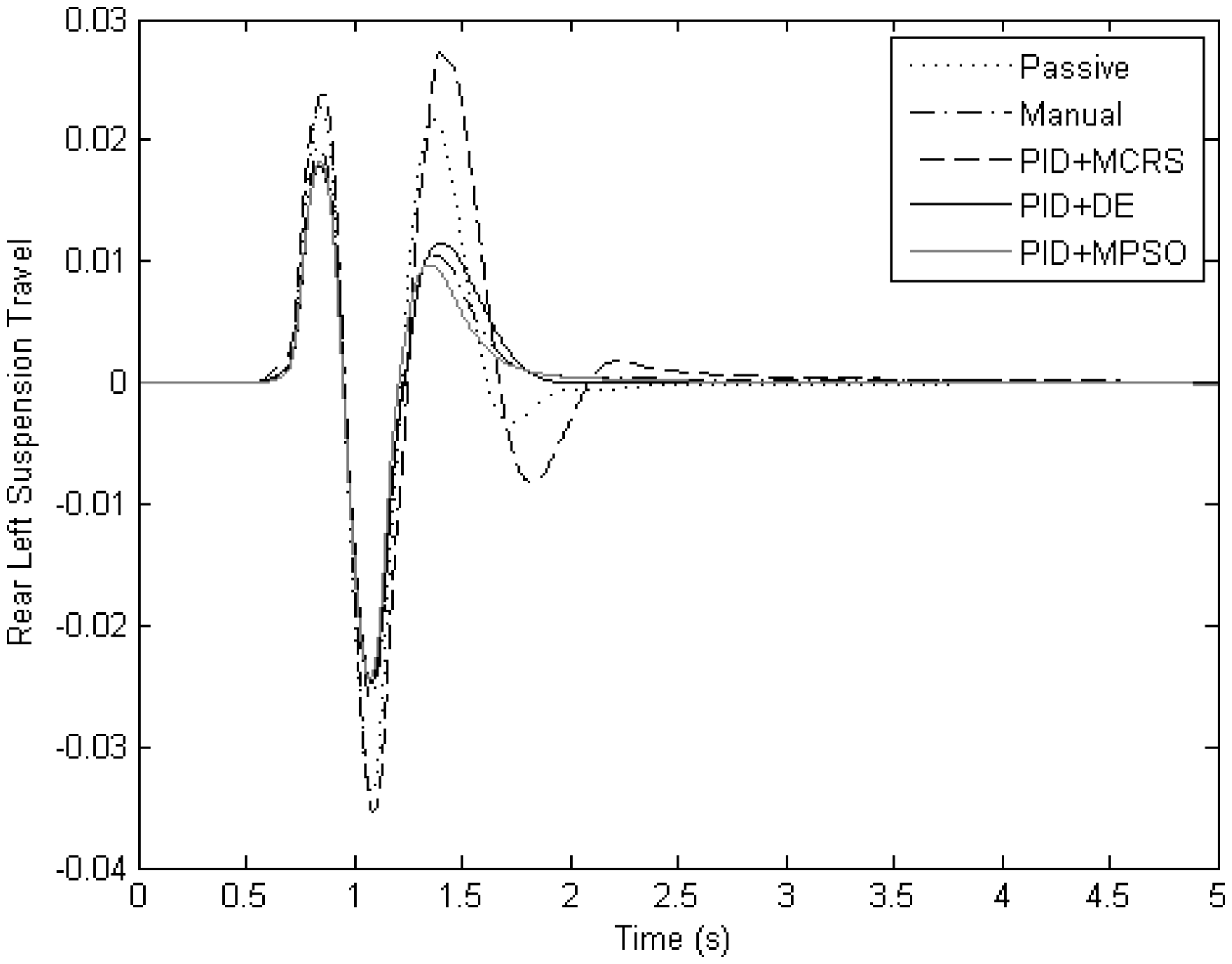
Illustration of the variation in suspension travel response using the proposed tuning methods. DE: differential evolution; MCRS: modified controlled random search; MPSO: modified particle swarm optimization; PID: proportional + integral + derivative.
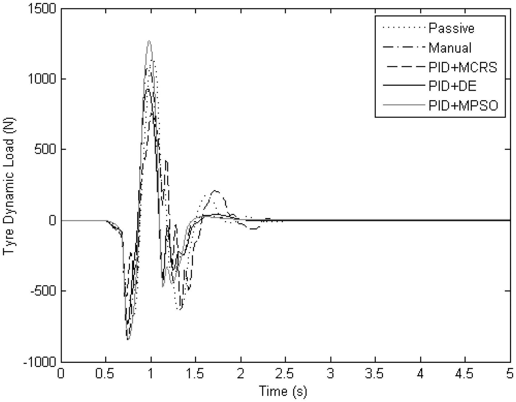
Variation in the tyre dynamic load experienced at the rear left suspension system for the various tuning policies. DE: differential evolution; MCRS: modified controlled random search; MPSO: modified particle swarm optimization; PID: proportional + integral + derivative.
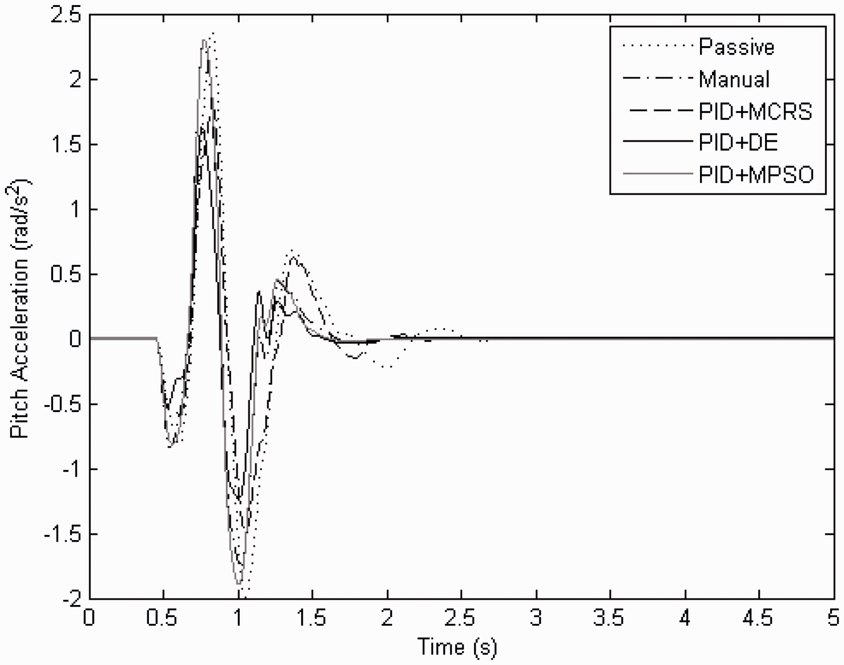
Vehicle body pitch acceleration for each of the tuning routines. DE: differential evolution; MCRS: modified controlled random search; MPSO: modified particle swarm optimization; PID: proportional + integral + derivative.
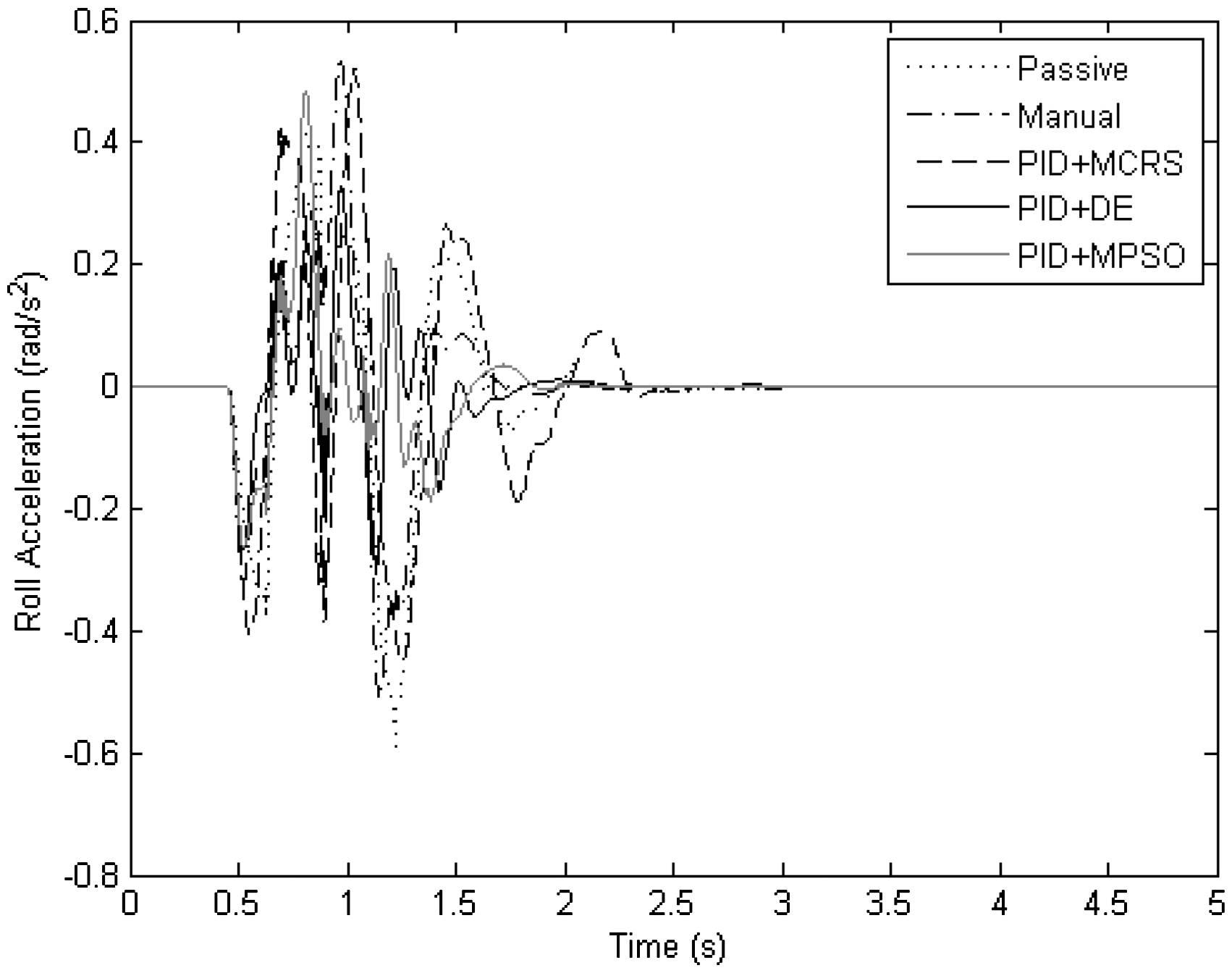
Vehicle body roll acceleration for the various tuning policies. DE: differential evolution; MCRS: modified controlled random search; MPSO: modified particle swarm optimization; PID: proportional + integral + derivative.
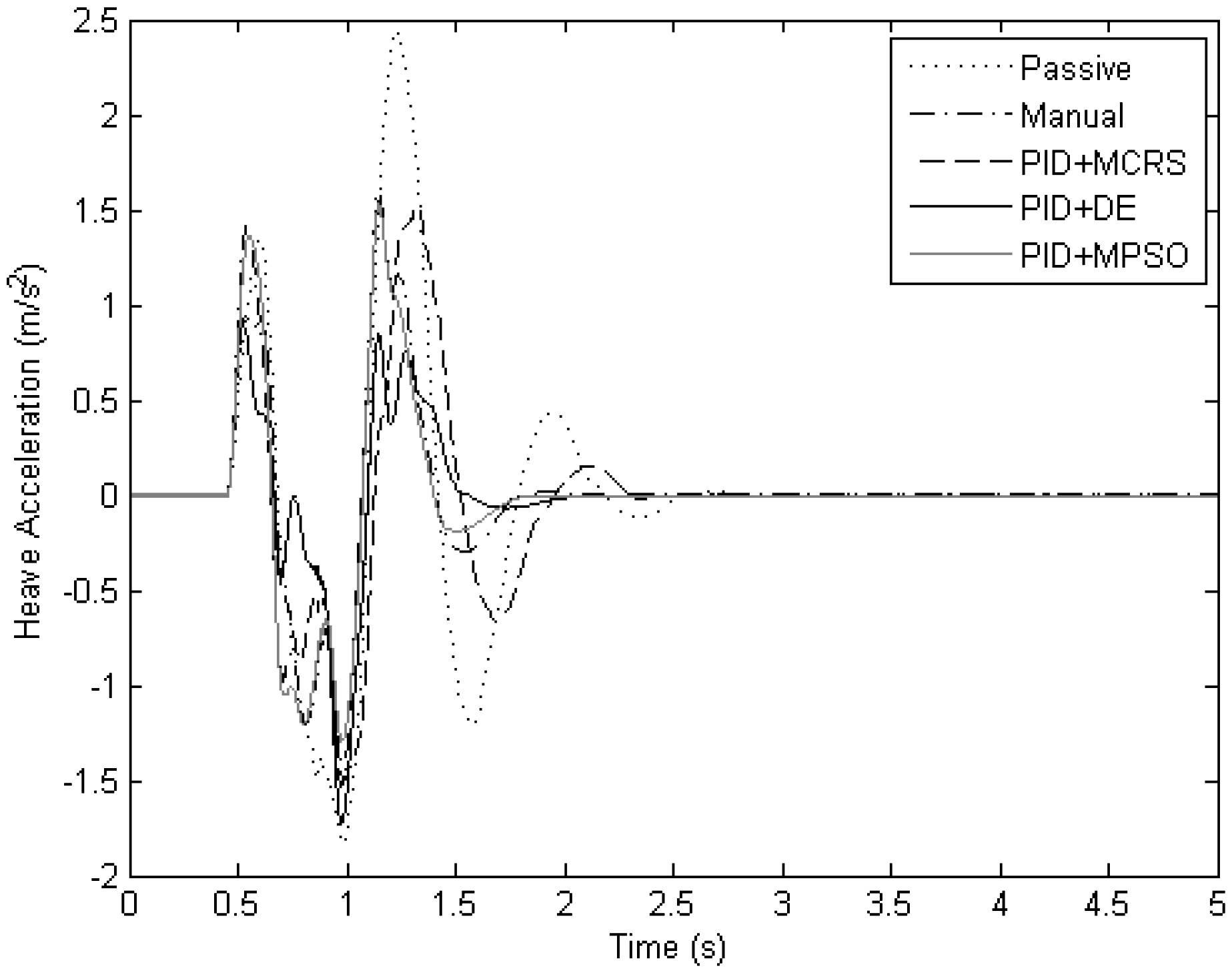
Ride comfort experienced for each of the recommended tuning methods. DE: differential evolution; MCRS: modified controlled random search; MPSO: modified particle swarm optimization; PID: proportional + integral + derivative.
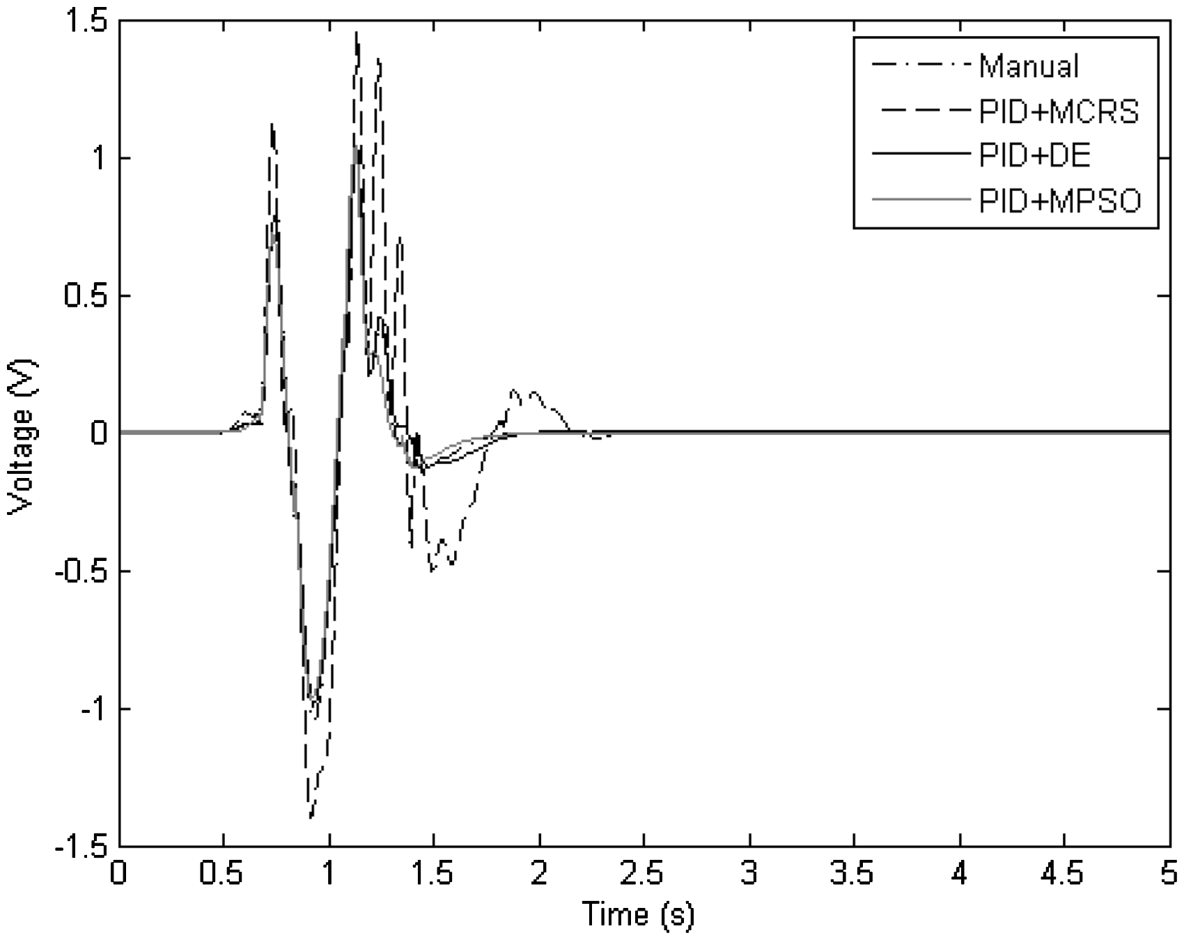
Difference in control input voltage produced using the suggested tuning approaches. DE: differential evolution; MCRS: modified controlled random search; MPSO: modified particle swarm optimization; PID: proportional + integral + derivative.
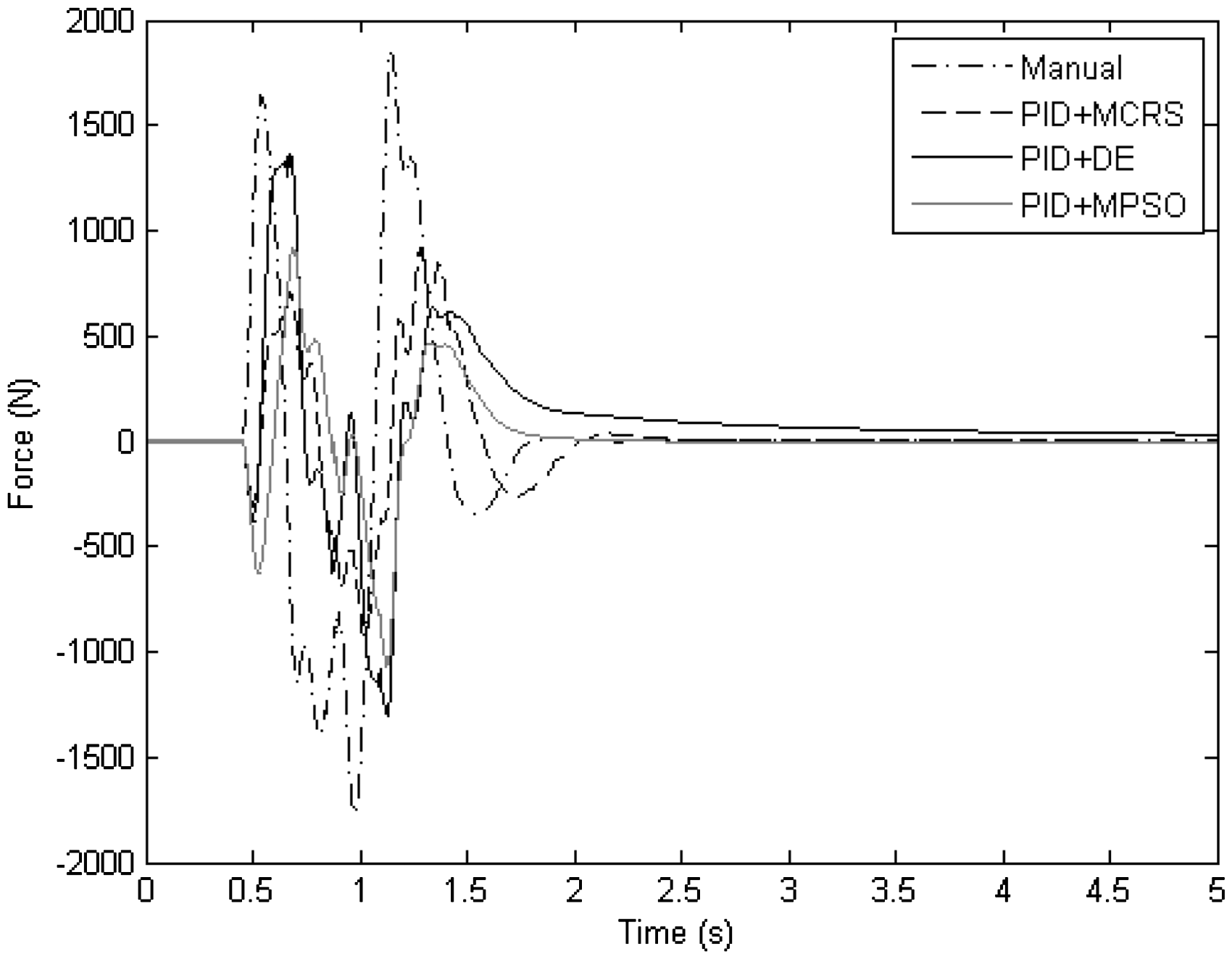
Effective hydraulic force applied to the vehicle chassis for the various tuning algorithms. DE: differential evolution; MCRS: modified controlled random search; MPSO: modified particle swarm optimization; PID: proportional + integral + derivative.
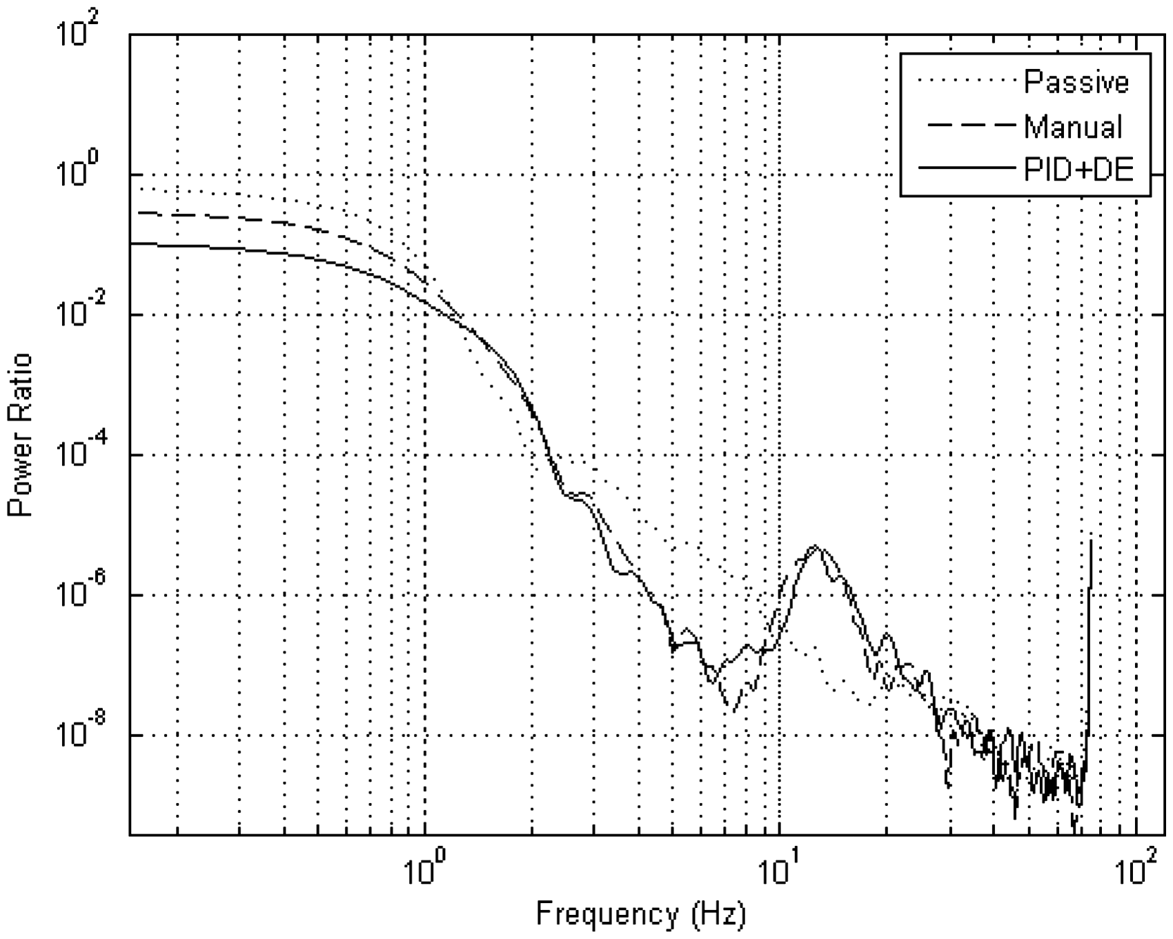
Frequency response comparative plot for the body-heave acceleration. DE: differential evolution; PID: proportional + integral + derivative.
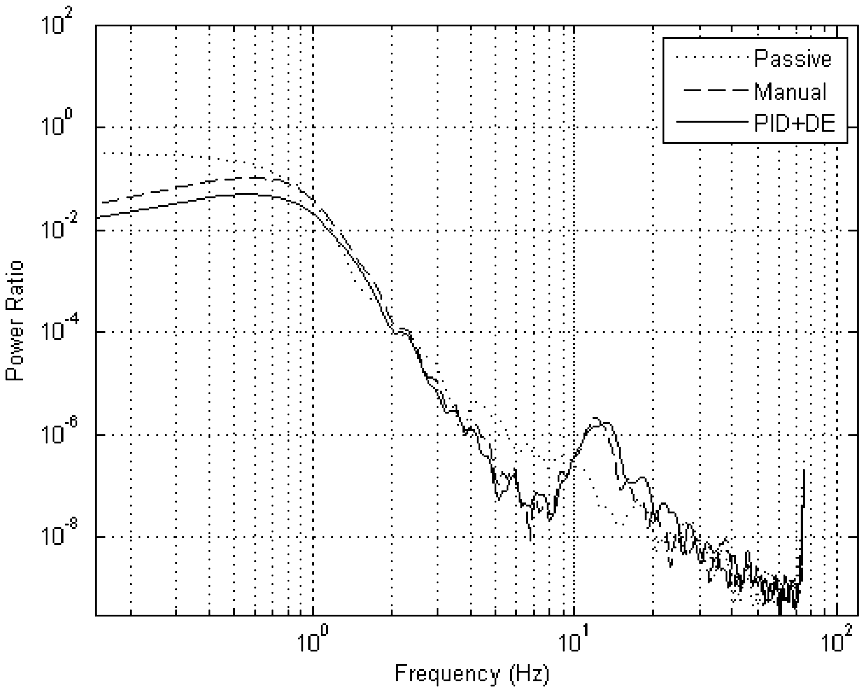
Comparative plot of frequency response pertaining to body pitch acceleration. DE: differential evolution; PID: proportional + integral + derivative.
Roll acceleration frequency response comparative plot for relevant cases. DE: differential evolution; PID: proportional + integral + derivative.
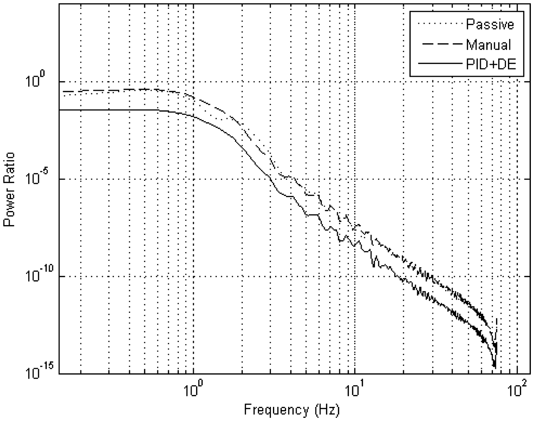
Frequency response for road holding. DE: differential evolution; PID: proportional + integral + derivative.
In terms of ride comfort, the PVSSs effectively behaved as a high-pass filter, whose high frequency signals were successfully attenuated. It possessed the worst attenuation at the onset where it had a magnitude of approximately 1 in the range of 0.01–1 Hz. On the contrary, the AVSS methods produced a significant improvement in this range as they were able to successfully attenuate signals therein, with the optimal controller performing best. Thereafter, the PVSS case possessed superior attenuation properties up until 2 Hz. Afterwards, the AVSS cases performed similarly and produced better attenuation results up to 10 Hz, where a resonant peak developed.
In relation to pitch acceleration, the PVSSs performed the worst at the onset which is by the standard regarded by the European Commission 47 as the most sensitive frequencies experienced by humans. The AVSS cases showed an improvement in comparison with the PVSSs in this regard, with the optimal case performing the best. In this range the power ratio did increase with increasing frequency but was still able to perform better than the PVSS case. At the onset of 1 Hz the power ratios of each case dropped off sharply inferring successful signal attenuation. The AVSS cases did however experience a resonance peak later at around 12 Hz, but the power ratios were comparatively low at these high frequencies, which implies successful attenuation.
With regards to roll acceleration, there was only a marginal variation between the PID-controlled and PVSS cases at the sensitive low frequencies. The DE-optimized case performed significantly better than its predecessors in this range but it produced an increasingly higher power ratio with increasing frequency. Thereafter, at around 1 Hz it began to perform worse than the other cases. From 11 Hz onwards the power ratio dropped off substantially indicating that the signals were henceforth attenuated considerably. A resonant peak did however develop for the AVSS cases at 10.5 Hz but the power ratio was low enough which saw the continued attenuation of input signals.
Road holding frequency plots resemble that of a high-pass filter where the sensitive low frequencies produced the largest peaks and the less sensitive high frequency signals were successfully attenuated. The PID-controlled and PVSS cases produced similar results for the whole range of frequencies where the optimal DE case performed significantly better. The continued superior performance of the optimal PID controller in relation to its counterparts for all suspension criteria in the sensitive low frequency ranges suggests two things. First, it was more successful than both its predecessor in resolving the conflicting trade-offs in ride comfort, road holding and vehicle handling. Second, it was successful in managing the sensitive low frequency signals for all suspension criteria. These results imply that controller tuning through global optimization methods does play a significant role in both resolving AVSS trade-offs and improving robustness to parameter variations.
Conclusion and future work
This paper presented applications of global and evolutionary optimization algorithms (CRS, DE, PSO, MCRS and MPSO) to tune the gains of multi-loop PID controllers for full-car nonlinear electrohydraulic AVSS to resolve the conflicting performance criteria. Multiple control loops were formulated to both regulate the controlled variable and maintain actuator integrity (stability).
The DE algorithm proved to be the most consistent as it was the only algorithm that maintained a desirable compromise and satisfactory performance in ride comfort, vehicle handling, suspension travel, road holding and power consumption. System performance through optimization achieved comparatively superior results for more severe disturbance than those that were reported in previous studies. Even though MPSO and MCRS algorithms significantly outperformed their predecessors, they did not however achieve the effectiveness of the DE algorithm. In the frequency domain, the DE still managed to maintain an edge in ride comfort and road holding over its manually tuned and PVSS counterparts. The successful performance of DE algorithm was due to the structure of its algorithm, which permits efficient exploration of the search space, and through certain acceptance conditions only replaces weaker solutions if and only if better solutions are found.
Further works must be extended to fault tolerant controller design for active suspension systems and experimental validation. Real world models contain more complexities that are ignored in the course of numerical simulations.
Footnotes
Declaration of conflicting interests
The author(s) declared no potential conflicts of interest with respect to the research, authorship, and/or publication of this article.
Funding
The author(s) received no financial support for the research, authorship, and/or publication of this article.