
Abstract
The control of a tri-axis computerized numerical control machine tool platform, which is driven by an AC servo motor is discussed in this paper. To establish a system model, the particle swarm optimization algorithm was used to transform the X–Y platform of a machine tool into a transfer function before simulation and verification of digital control was done using MATLAB. The control methods used in this study include proportional-integral-derivative control, quantitative feedback design theory and sliding mode control. They were realized with C# and the errors of motion trajectories generated by the controllers were observed. It was concluded that of the three methods studied, sliding mode control produced the lowest error rate.
Keywords
Introduction
The rapid advance of science has caused the need for precision machining to reach into every branch of technology and industry. There are many methods to analyze and control the nonlinear systems, such as variational principle. 1 After numerical analysis, the control schemes are always applied to control the systems. Proportional-integral-derivative (PID) is the most commonly used control method for precision computerized numerical control (CNC) machine tools. Whether PID control is the best control method for such a system is debatable. The focus of this study is on several of the methods commonly used for CNC machine tool control.
Popular control methods for CNC machine tools include: PID control,1–3 fuzzy control,4,5 extension control, 6 quantitative feedback design theory (QFT) control,7–9 sliding mode control (SMC),10–12 and others. The smart algorithms for adaptive control such as ant colony optimization (ACO), particle swarm optimization (PSO), and the genetic algorithm (GA),13,14 have also been widely used.
Each of these control methods has advantages and disadvantage. PID control is independent of overall system architecture. Only three different parameters need to be adjusted to achieve stable control. The use of extension control requires the establishment of a controlled field and a classical field, the range of which can be extended indefinitely
The X and Y slides of a milling machine were used as the experimental platform in this study. The platform, which is used for moving a work piece, needs to be well controlled and requires precision of motion trajectory. A system model was built for the machine 15 and this was transformed into a transfer function using PSO. The compatibility was based on the system model calculated from the signal source of the actual system and feedback data16,17 and a digital simulation was then carried out using MATLAB.
PID, QFT and SMC control were used in this study. Verification was carried out in the actual system after calibration by simulation experiment. The X–Y slides were driven by AC servo motors, which receive commands sent from the system through a motion control card. A final comparison of errors between motion trajectories was done to determine the most suitable controller for the system.
System model
System structure
The equipment used in this study was the X and Y assembly of a milling machine, as shown in Figure 1. The system includes a computer, AC servo motors and the X–Y platform (the machine slides and worktable). System performance response via encoder and simulation as shown in Figure 2.
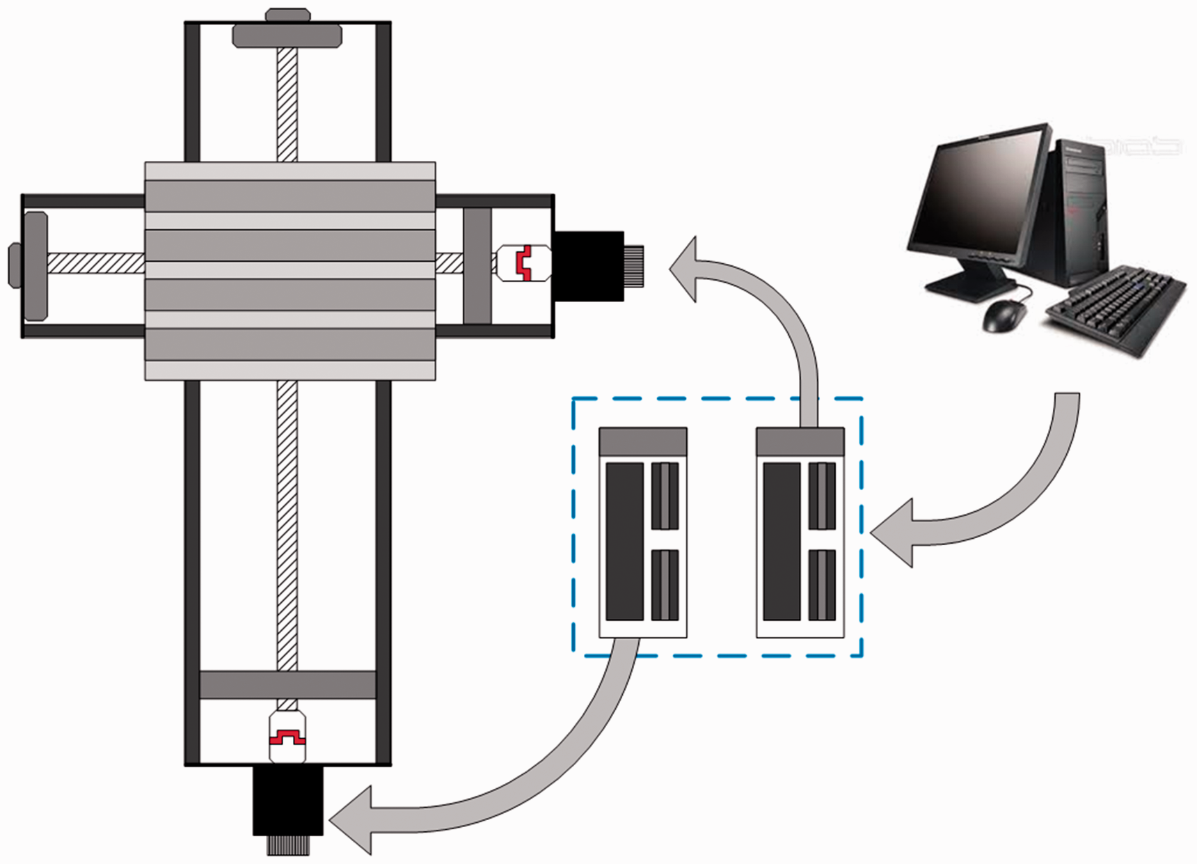
The X–Y platform of the machine tool.
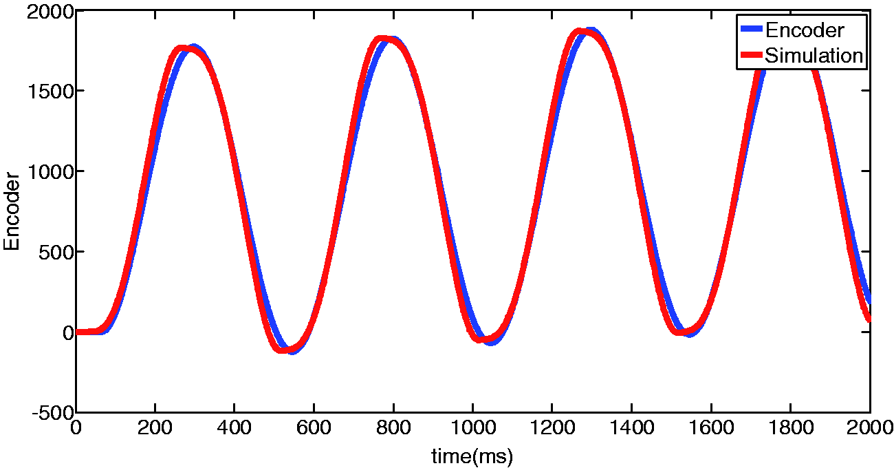
Feedback from encoder.
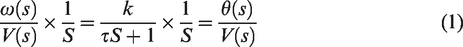
The mechanism used in this study works as follows: the AC servo motors connect to the drive screws of each slide X and Y through ball bearing couplings. The motor control card receives commands from the computer to drive the slides and move the X–Y platform. A standard first-order transfer function was chosen for the architecture of the controlled object, as shown in equation (1). Since the feedback data is position, the architecture of the controlled object is changed to use voltage as input and angular position as output so that the system model is more like an actual system.
System identification
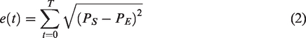
The notion of system identification18,19 is that for the same signal given, the output from the actual system and that of the simulation should be the same. The system model in Figure 1 was obtained from PSO using the signal from the encoder. PSO was used to calculate the architecture of the system model that best fitted the system and the conditional function was designed to be the error between the simulation and the actual system. The goal being error reduction. In equation (2),
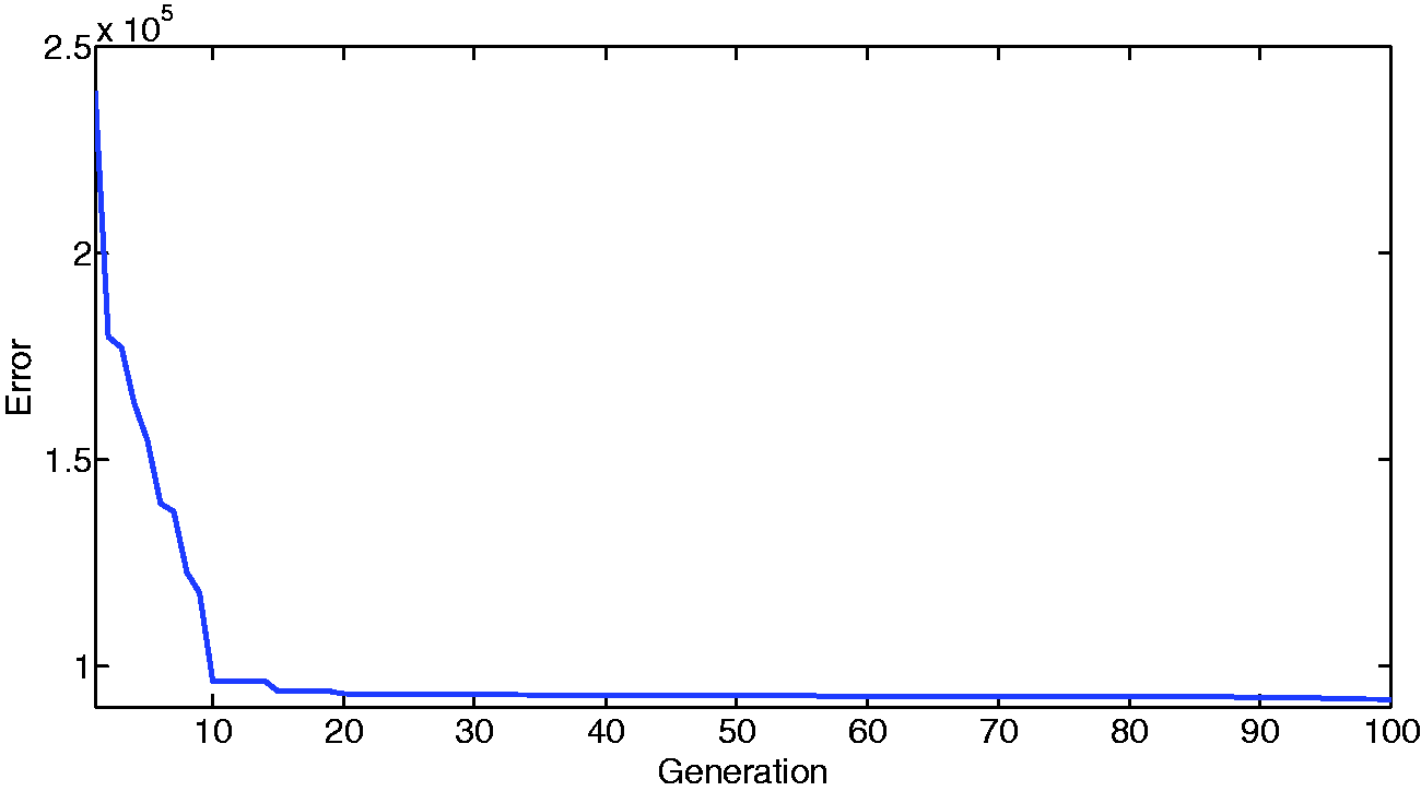
Error convergence diagram for system identification.
Sliding mode control
Most control systems are nonlinear, and in this study SMC was used to turn a nonlinear control system into a linear one to improve effectiveness.
The purpose of sliding mode trajectory control is to keep the system operating on the hyperplane. To achieve this SMC works in two modes, the sliding mode and approaching mode. The mode in which the system operates is decided by the sliding function

Ideally,

When SMC is being used, to get the system to enter sliding mode quickly, the Lyapunov theorem can be used to verify system stability. The Lyapunov function is defined in equation (6). When conditions are stable, as shown in equations (7) and (8), and are satisfied by Lyapunov function, the system will enter stable equilibrium very quickly.


PI-type SMC was chosen for this study. The design being mainly based on published research. The approach mode is different from that used in traditional SMC. The design is shown in equation (9).

Equation (10) is then derived from equations (4), (5) and (9):

The specific Lyapunov function is defined based on equation (11). Where
Equation (11) is then differentiated as shown in equation (12).

Equations (12) and (13) show that the controller will stabilize gradually, which means that the system will operate along the trajectory of the target signal after entering sliding mode.
Experimental results
SMC simulation experiment
In order for SMC to remain in an optimal situation, the two parameters for the approach mode,
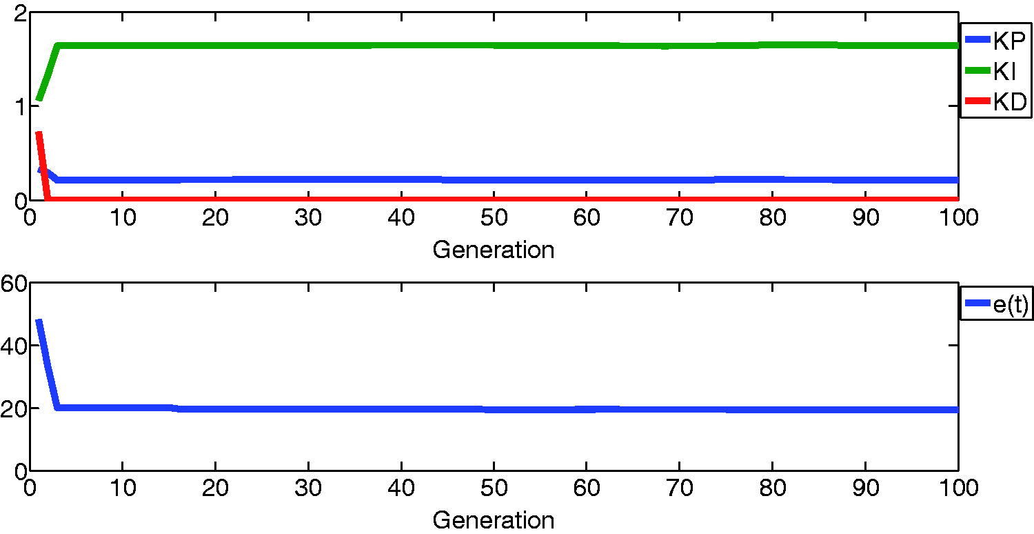
PSO conditional SMC function convergence diagram.
SMC motion trajectory diagram.
Simulation experiment of PSO–PID control
Proportional-integral-derivative controllers are simple and easy to implement. Commercial controllers, as used in CNC machine tools with AC motor drives, all use PID control. The controller has three main parameters:
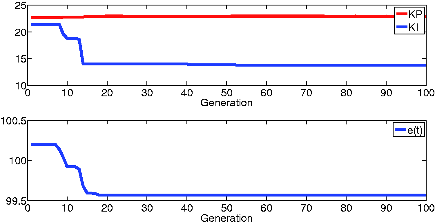
PSO conditional function convergence diagram, X-axis PID controller.
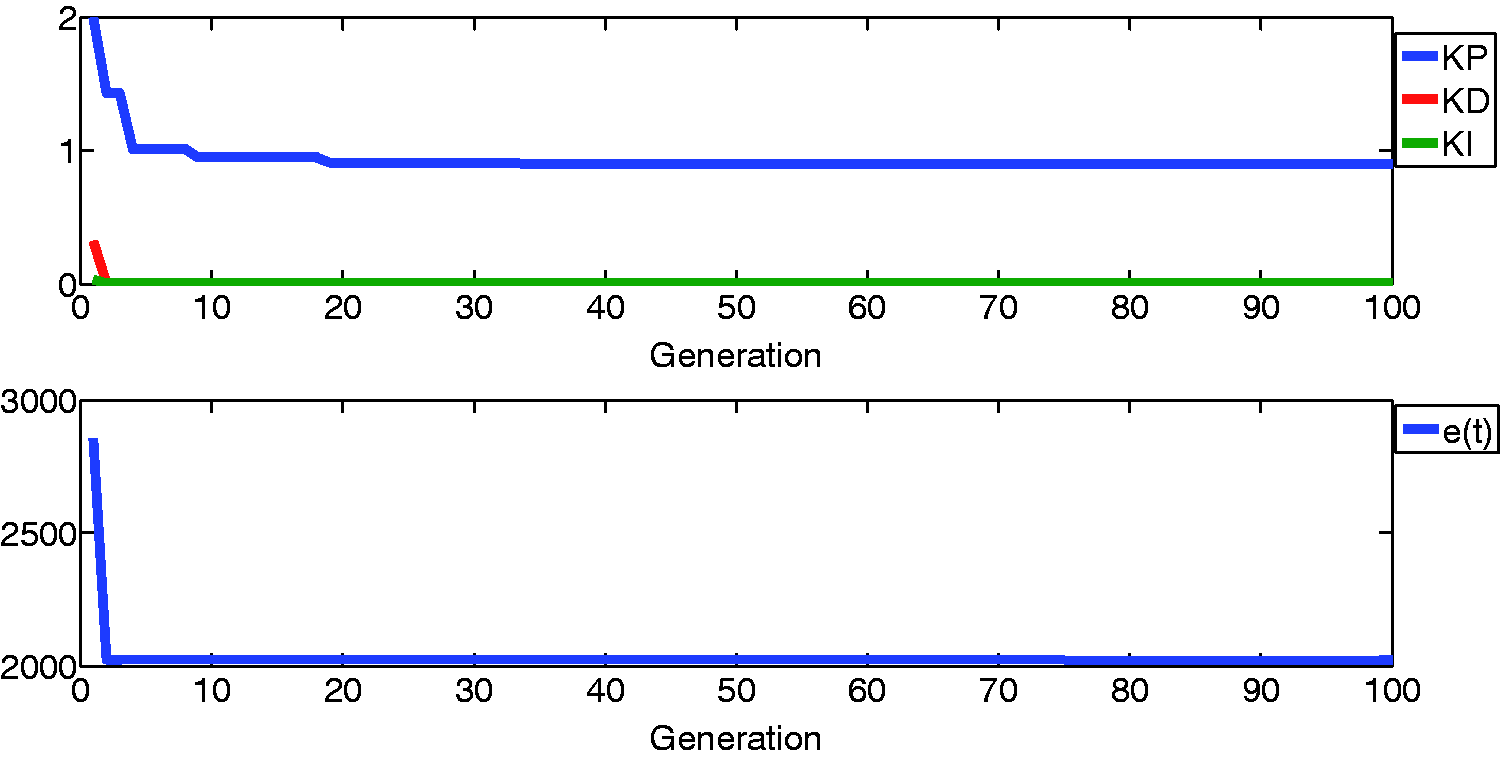
PSO conditional function convergence diagram, Y-axis PID controller.
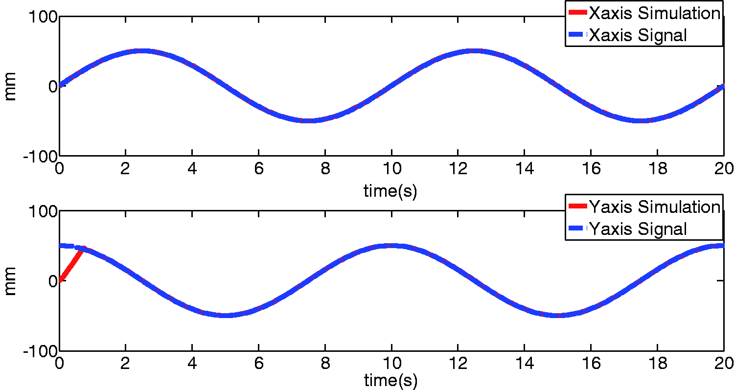
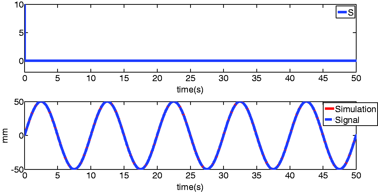
PSO–PID controller motion trajectory diagrams.
QFT control simulation experiment20,21
QFT control works in a similar way to that described in the previous section. The transfer functions of the QFT controllers for the two axes can be derived after matching system architectures of both axes. However, discrete system functions of the controllers for the two axes will be calculated from continuous system functions using a Z-transform. The motion trajectories of the X-axis and Y-axis are shown in Figure 9.
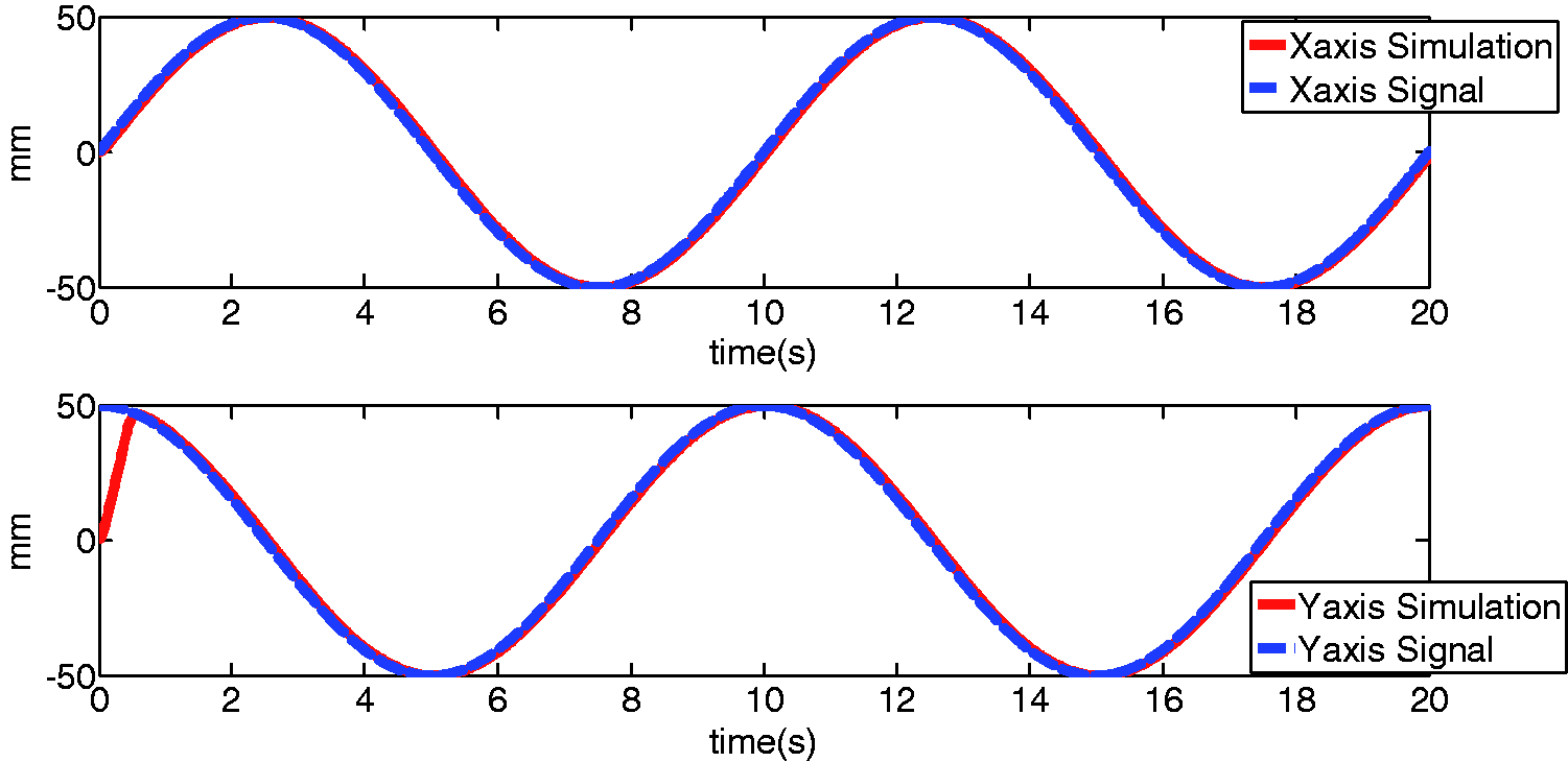
Simulated motion trajectory diagram, X, Y-axis QFT controller.
Experiment results
The equipment used in this study was the base of a CNC milling machine, as shown in Figure 10. The computer sends commands to the AC servo motors and drives the feed screws, which in turn move the platform. Two 2000 W DELTA ASD-A2 series servo motors were used. The encoder can be set to the maximum of 32,000 pulses/cycle. The pitch of the thread on the feed screws was 16 mm, as shown in Figure 11.
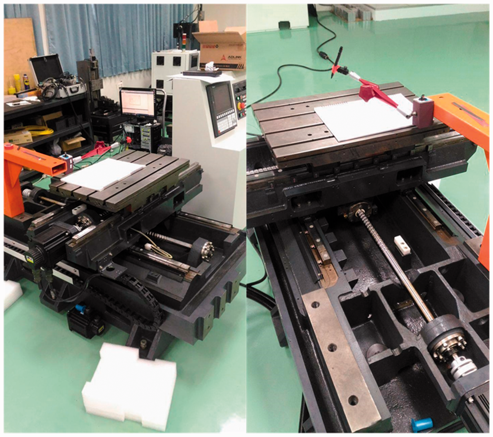
The X–Y platform used in this study.
Diagram of feed screw and nut.
A PC-based ADLINK PCI-8254 motion control card was used in this study. The controller was realized with C# through the ADLINK API system. Parameters
Experiments in this study are conducted by comparing the results of drawing circles of 50 mm in radius. The starting point is on the border line. Signal sources are
Three types of controllers were used to operate the X–Y movements. The errors and circle drawing results were obtained based from encoder feedback, as shown in Figures 12 to 16. It is clear that SMC control has the best performance with respect to tracking signal source, and has an error of about 0.45 mm. QFT, which has error of nearly 0.6 mm, is still considered to be relatively stable. However, the PID controller is somewhat less precise when controlling its target system and other compensation would be needed to assist in calibration.
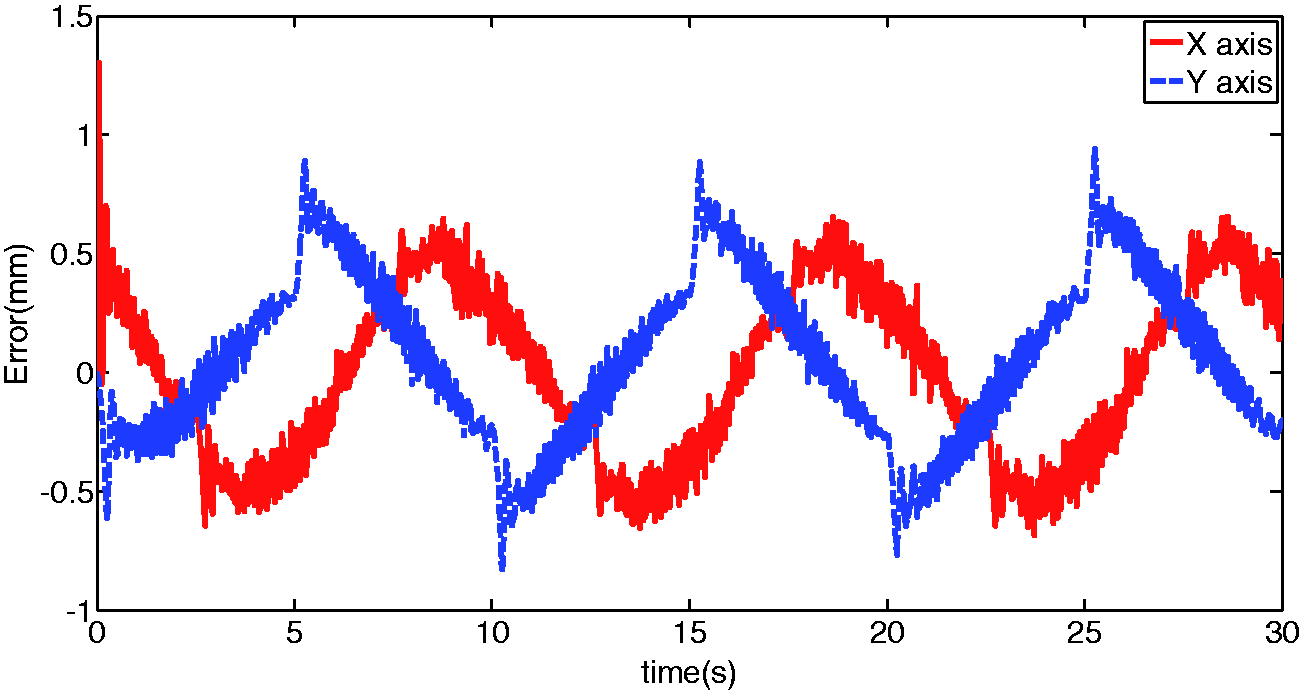
Circle drawing errors, PID control.
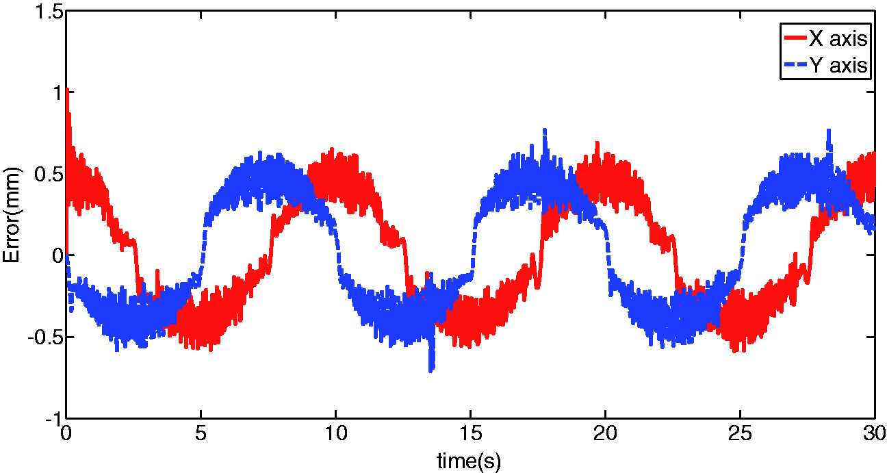
Circle drawing errors, QFT control.
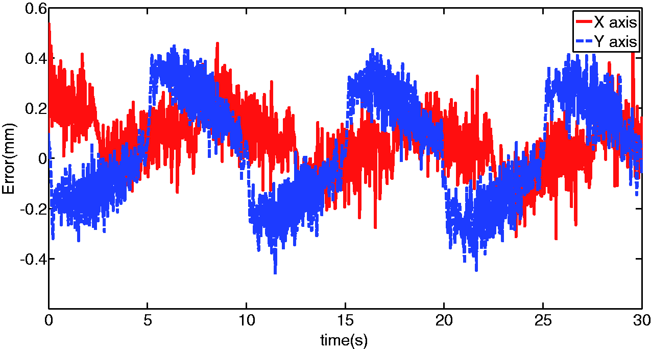
Circle drawing errors, SMC control.
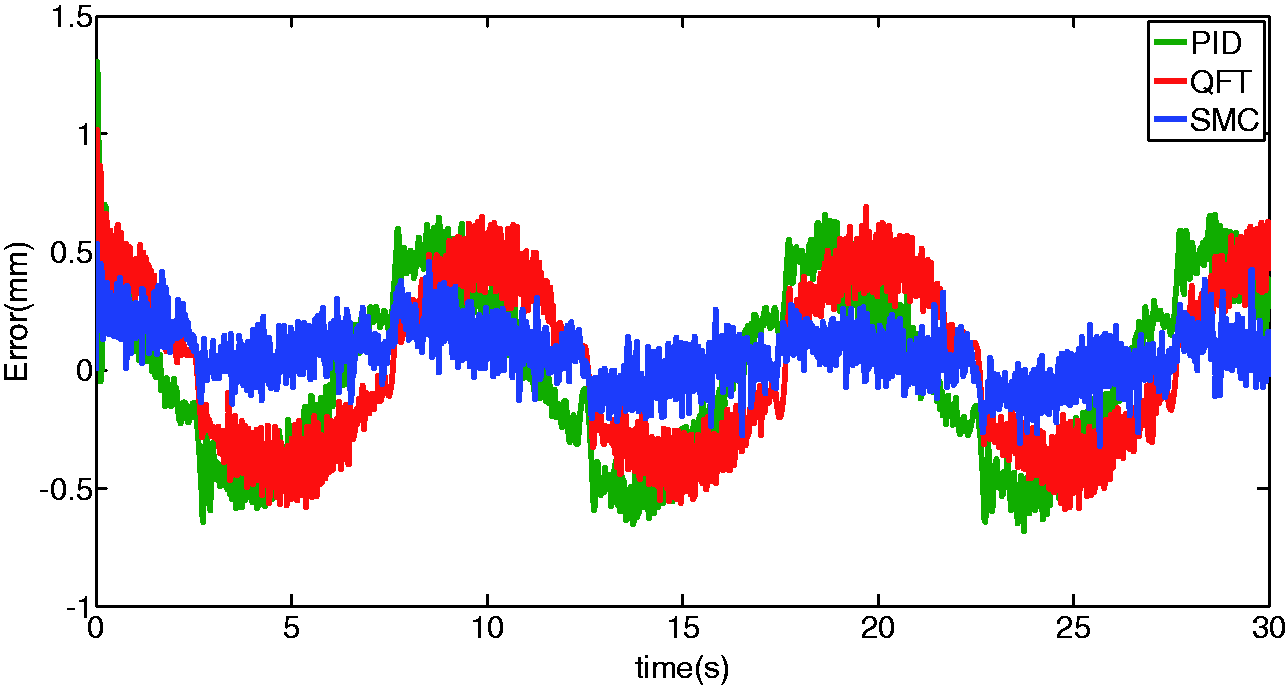
Comparison of X-axis errors for the three controllers.
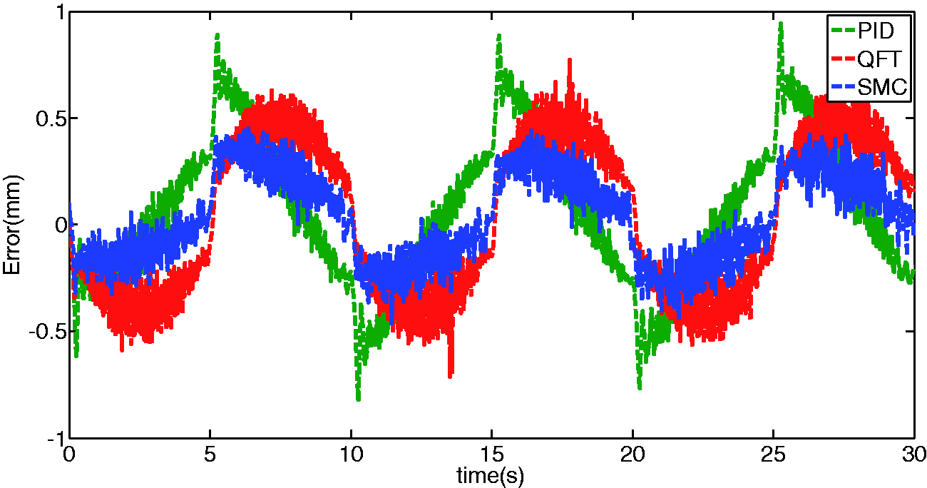
Comparison of errors between Y-axis controllers.
Conclusion
In this study, the equipment was digitized by modeling using the PSO smart algorithm. The performance of the controllers could readily be assessed in the simulated systems. Since designing QFT and SMC control requires frequency response of the overall system, precise system modeling would facilitate more appropriate controller designs. The best controller parameter values can be decided by accurate operation of the simulated systems. Comparisons were made between three control methods, PID, QFT and SMC, and observations of feedback signals from the encoder, showed SMC to have the more precise control, with an error of about 0.45 mm from the target trajectory. With QFT and PID, the errors were about 0.6 mm and nearly 1.0 mm, respectively. In this paper, we use a robust controller to control the CNC system. In the future, we will consider trying a variational iteration method-based or homotopy perturbation method-based smart algorithm to find the optimal gains.
Footnotes
Declaration of conflicting interests
The author(s) declared no potential conflicts of interest with respect to the research, authorship, and/or publication of this article.
Funding
The author(s) disclosed receipt of the following financial support for the research, authorship, and/or publication of this article: This research project received financial support from the Yunnan Province Science and Technology Department and Education Department Project of China (2017FH001-067, 2017FH001-117, 2016ZDX127).